EP1970903A1 - Head using near-field light and information recorder - Google Patents
Head using near-field light and information recorder Download PDFInfo
- Publication number
- EP1970903A1 EP1970903A1 EP06834653A EP06834653A EP1970903A1 EP 1970903 A1 EP1970903 A1 EP 1970903A1 EP 06834653 A EP06834653 A EP 06834653A EP 06834653 A EP06834653 A EP 06834653A EP 1970903 A1 EP1970903 A1 EP 1970903A1
- Authority
- EP
- European Patent Office
- Prior art keywords
- field
- magnetic pole
- light
- magnetic
- optical head
- Prior art date
- Legal status (The legal status is an assumption and is not a legal conclusion. Google has not performed a legal analysis and makes no representation as to the accuracy of the status listed.)
- Ceased
Links
Images



Classifications
-
- G—PHYSICS
- G11—INFORMATION STORAGE
- G11B—INFORMATION STORAGE BASED ON RELATIVE MOVEMENT BETWEEN RECORD CARRIER AND TRANSDUCER
- G11B5/00—Recording by magnetisation or demagnetisation of a record carrier; Reproducing by magnetic means; Record carriers therefor
- G11B5/012—Recording on, or reproducing or erasing from, magnetic disks
-
- G—PHYSICS
- G11—INFORMATION STORAGE
- G11B—INFORMATION STORAGE BASED ON RELATIVE MOVEMENT BETWEEN RECORD CARRIER AND TRANSDUCER
- G11B5/00—Recording by magnetisation or demagnetisation of a record carrier; Reproducing by magnetic means; Record carriers therefor
- G11B5/02—Recording, reproducing, or erasing methods; Read, write or erase circuits therefor
-
- G—PHYSICS
- G11—INFORMATION STORAGE
- G11B—INFORMATION STORAGE BASED ON RELATIVE MOVEMENT BETWEEN RECORD CARRIER AND TRANSDUCER
- G11B5/00—Recording by magnetisation or demagnetisation of a record carrier; Reproducing by magnetic means; Record carriers therefor
- G11B5/127—Structure or manufacture of heads, e.g. inductive
- G11B5/1278—Structure or manufacture of heads, e.g. inductive specially adapted for magnetisations perpendicular to the surface of the record carrier
-
- G—PHYSICS
- G11—INFORMATION STORAGE
- G11B—INFORMATION STORAGE BASED ON RELATIVE MOVEMENT BETWEEN RECORD CARRIER AND TRANSDUCER
- G11B5/00—Recording by magnetisation or demagnetisation of a record carrier; Reproducing by magnetic means; Record carriers therefor
- G11B5/127—Structure or manufacture of heads, e.g. inductive
- G11B5/31—Structure or manufacture of heads, e.g. inductive using thin films
- G11B5/3109—Details
- G11B5/313—Disposition of layers
- G11B5/3133—Disposition of layers including layers not usually being a part of the electromagnetic transducer structure and providing additional features, e.g. for improving heat radiation, reduction of power dissipation, adaptations for measurement or indication of gap depth or other properties of the structure
- G11B5/314—Disposition of layers including layers not usually being a part of the electromagnetic transducer structure and providing additional features, e.g. for improving heat radiation, reduction of power dissipation, adaptations for measurement or indication of gap depth or other properties of the structure where the layers are extra layers normally not provided in the transducing structure, e.g. optical layers
-
- G—PHYSICS
- G11—INFORMATION STORAGE
- G11B—INFORMATION STORAGE BASED ON RELATIVE MOVEMENT BETWEEN RECORD CARRIER AND TRANSDUCER
- G11B7/00—Recording or reproducing by optical means, e.g. recording using a thermal beam of optical radiation by modifying optical properties or the physical structure, reproducing using an optical beam at lower power by sensing optical properties; Record carriers therefor
- G11B7/12—Heads, e.g. forming of the optical beam spot or modulation of the optical beam
- G11B7/135—Means for guiding the beam from the source to the record carrier or from the record carrier to the detector
- G11B7/1387—Means for guiding the beam from the source to the record carrier or from the record carrier to the detector using the near-field effect
-
- B—PERFORMING OPERATIONS; TRANSPORTING
- B82—NANOTECHNOLOGY
- B82Y—SPECIFIC USES OR APPLICATIONS OF NANOSTRUCTURES; MEASUREMENT OR ANALYSIS OF NANOSTRUCTURES; MANUFACTURE OR TREATMENT OF NANOSTRUCTURES
- B82Y10/00—Nanotechnology for information processing, storage or transmission, e.g. quantum computing or single electron logic
-
- G—PHYSICS
- G01—MEASURING; TESTING
- G01Q—SCANNING-PROBE TECHNIQUES OR APPARATUS; APPLICATIONS OF SCANNING-PROBE TECHNIQUES, e.g. SCANNING PROBE MICROSCOPY [SPM]
- G01Q80/00—Applications, other than SPM, of scanning-probe techniques
-
- G—PHYSICS
- G11—INFORMATION STORAGE
- G11B—INFORMATION STORAGE BASED ON RELATIVE MOVEMENT BETWEEN RECORD CARRIER AND TRANSDUCER
- G11B11/00—Recording on or reproducing from the same record carrier wherein for these two operations the methods are covered by different main groups of groups G11B3/00 - G11B7/00 or by different subgroups of group G11B9/00; Record carriers therefor
- G11B11/10—Recording on or reproducing from the same record carrier wherein for these two operations the methods are covered by different main groups of groups G11B3/00 - G11B7/00 or by different subgroups of group G11B9/00; Record carriers therefor using recording by magnetic means or other means for magnetisation or demagnetisation of a record carrier, e.g. light induced spin magnetisation; Demagnetisation by thermal or stress means in the presence or not of an orienting magnetic field
- G11B11/105—Recording on or reproducing from the same record carrier wherein for these two operations the methods are covered by different main groups of groups G11B3/00 - G11B7/00 or by different subgroups of group G11B9/00; Record carriers therefor using recording by magnetic means or other means for magnetisation or demagnetisation of a record carrier, e.g. light induced spin magnetisation; Demagnetisation by thermal or stress means in the presence or not of an orienting magnetic field using a beam of light or a magnetic field for recording by change of magnetisation and a beam of light for reproducing, i.e. magneto-optical, e.g. light-induced thermomagnetic recording, spin magnetisation recording, Kerr or Faraday effect reproducing
- G11B11/10532—Heads
- G11B11/10534—Heads for recording by magnetising, demagnetising or transfer of magnetisation, by radiation, e.g. for thermomagnetic recording
- G11B11/10536—Heads for recording by magnetising, demagnetising or transfer of magnetisation, by radiation, e.g. for thermomagnetic recording using thermic beams, e.g. lasers
-
- G—PHYSICS
- G11—INFORMATION STORAGE
- G11B—INFORMATION STORAGE BASED ON RELATIVE MOVEMENT BETWEEN RECORD CARRIER AND TRANSDUCER
- G11B11/00—Recording on or reproducing from the same record carrier wherein for these two operations the methods are covered by different main groups of groups G11B3/00 - G11B7/00 or by different subgroups of group G11B9/00; Record carriers therefor
- G11B11/10—Recording on or reproducing from the same record carrier wherein for these two operations the methods are covered by different main groups of groups G11B3/00 - G11B7/00 or by different subgroups of group G11B9/00; Record carriers therefor using recording by magnetic means or other means for magnetisation or demagnetisation of a record carrier, e.g. light induced spin magnetisation; Demagnetisation by thermal or stress means in the presence or not of an orienting magnetic field
- G11B11/105—Recording on or reproducing from the same record carrier wherein for these two operations the methods are covered by different main groups of groups G11B3/00 - G11B7/00 or by different subgroups of group G11B9/00; Record carriers therefor using recording by magnetic means or other means for magnetisation or demagnetisation of a record carrier, e.g. light induced spin magnetisation; Demagnetisation by thermal or stress means in the presence or not of an orienting magnetic field using a beam of light or a magnetic field for recording by change of magnetisation and a beam of light for reproducing, i.e. magneto-optical, e.g. light-induced thermomagnetic recording, spin magnetisation recording, Kerr or Faraday effect reproducing
- G11B11/1055—Disposition or mounting of transducers relative to record carriers
- G11B11/10552—Arrangements of transducers relative to each other, e.g. coupled heads, optical and magnetic head on the same base
- G11B11/10554—Arrangements of transducers relative to each other, e.g. coupled heads, optical and magnetic head on the same base the transducers being disposed on the same side of the carrier
-
- G—PHYSICS
- G11—INFORMATION STORAGE
- G11B—INFORMATION STORAGE BASED ON RELATIVE MOVEMENT BETWEEN RECORD CARRIER AND TRANSDUCER
- G11B5/00—Recording by magnetisation or demagnetisation of a record carrier; Reproducing by magnetic means; Record carriers therefor
- G11B2005/0002—Special dispositions or recording techniques
- G11B2005/0005—Arrangements, methods or circuits
- G11B2005/001—Controlling recording characteristics of record carriers or transducing characteristics of transducers by means not being part of their structure
-
- G—PHYSICS
- G11—INFORMATION STORAGE
- G11B—INFORMATION STORAGE BASED ON RELATIVE MOVEMENT BETWEEN RECORD CARRIER AND TRANSDUCER
- G11B5/00—Recording by magnetisation or demagnetisation of a record carrier; Reproducing by magnetic means; Record carriers therefor
- G11B2005/0002—Special dispositions or recording techniques
- G11B2005/0005—Arrangements, methods or circuits
- G11B2005/0021—Thermally assisted recording using an auxiliary energy source for heating the recording layer locally to assist the magnetization reversal
Definitions
- the invention relates to a near-field optical head using near-field light having a resolution beyond the diffraction limit by localizing light to a minute area, and it particularly relates to a near-field optical head implementing an ultrahigh recording density by using both of near-field light and a magnetic field and an information recording apparatus including it.
- information recording/reproducing apparatus In order to respond the rapid increase of the amounts of image/motion picture information in the recent information society, information recording/reproducing apparatus have been increased in capacity and decreased in size.
- the density of an optical information recording/reproducing apparatus is increased by using light in a short wavelength since the recording density depends on the optical wavelength.
- the principle of recording and reproducing using near-field light has received attention as a method for implementing the density independent of wavelengths.
- the near-field light assisted magnetic recording that irradiates near-field light only to the minute area to heat and reduce the coercivity and then magnetizes the minute area is seen as a promising candidate of the next generation of the principle of recording and reproducing.
- a head of near-field light assisted magnetic recording has a conventional structure having a near-field light generating element adjacent to a recording magnetic pole of a magnetic head.
- the near-field light generating element has multiple planer metallic arms within an optical waveguide and has an opening at each of the distal ends ( JP-A-2005-515578 (Pages 6 and 7, Fig. 2 ): Patent Document 1).
- the structure has been also proposed in which near-field light is generated at a position adjacent to a magnetic pole by installing a solid immersion lens on a flying head ( JP-A-10-162444 (Pages 18 and 19, Fig. 13): Patent Document 2).
- the importation of light from a light source to an optical waveguide employs a method that irradiates light from a laser directly to an optical waveguide (Patent Document 1) or a solid immersion lens (Patent Document 2).
- the near-field light generating element has a complicated structure within the waveguide, and it is difficult to form with high precision.
- the recording magnetic pole and the near-field light generating element are separate, the recording magnetic pole and the near-field light generating element must be placed with high precision. Otherwise, the magnetic field from the recording magnetic pole and the near-field light from the near-field light generating element cannot be directed to a desired position on a recording medium. Therefore, easy production of the head has not been allowed.
- the invention was made in view of the aforesaid points. It is an object of the invention to provide a near-field optical head which can be produced easily even without finely aligning components in the head and an information recording apparatus including the near-field optical head.
- the substance of the first characteristic according to the invention is a near-field optical head that generates near-field light to heat a predetermined area of a medium and applies a magnetic field to the predetermined area to record information
- the head including an optical waveguide having a path for propagating a pencil of light, and a near-field light generating element having a magnetic pole gap having an opening at the position facing against the predetermined area and collecting the pencil of light emitted from the optical waveguide and simultaneously propagating the collected pencil of light to the magnetic pole gap to generate the near-field light, wherein the magnetic pole gap is formed by a magnetic pole that applies a magnetic field to the predetermined area.
- the substance of the second characteristic according to the invention is that the near-field light generating element includes a pyramidal tip containing a transparent material, and the magnetic pole gap is formed at the pointed end of the pyramidal tip.
- the substance of the third characteristic according to the invention is that a part of the magnetic pole is provided at a part of a side of the pyramidal tip.
- the head further includes a magnetic recording element having the magnetic pole and a coil that causes the magnetic pole to generate a magnetic field
- the near-field light generating element and the magnetic recording element are provided on a substantially flat-shaped substrate
- the substrate has an air-bearing surface at the position where the substrate faces against the medium, and the air-bearing surface is formed such that the near-field light generating element and the magnetic recording element can levitate by keeping a predetermined distance from the surface of the medium by using the air-bearing force generated by the rotation of the medium.
- the substance of the fifth characteristic according to the invention is that the magnetic pole contains an opaque material.
- the substance of the sixth characteristic according to the invention is that a part of a side of the pyramidal tip has a metallic film.
- the substance of the seventh characteristic according to the invention is that the pyramidal tip has a quadrangular pyramid, and two facing sides of the four sides have a part of the magnetic pole.
- the substance of the eighth characteristic according to the invention is that the pyramidal tip has a quadrangular pyramid, and two facing sides of the four sides have a metallic film.
- the substance of the ninth characteristic according to the invention is that the near-field optical head further includes a magneto-resistive element that reads information recorded on the medium, wherein the magnetic tunnel junction is provided on the same substrate as that of the magnetic recording element.
- the substance of the tenth characteristic according to the invention is an information recording apparatus including a light source, a medium that records information with the inversion of magnetization, a near-field optical head having a near-field light generating element that receives light from the light source and generates near-field light from an optical minute opening, a motor that rotates the medium, a suspension arm that brings the near-field optical head closely to the medium, and an actuator that moves the suspension arm to a predetermined position of the medium, wherein the near-field optical head has a first magnetic pole and a second magnetic pole that faces against the first magnetic pole through a magnetic pole gap, and the near-field optical head heats a surface of the medium by generating the near-field light from the optical minute opening and records information on the medium by inverting the magnetization with the magnetic field generated within the magnetic pole gap between the first magnetic pole and the second magnetic pole.
- the substance of the eleventh characteristic according to the invention is that the near-field light generating element has a pyramidal tip containing a transparent material, and the magnetic pole gap is provided at the pointed end of the pyramidal tip.
- the substance of the twelfth characteristic according to the invention is that a part of the first magnetic pole and the second magnetic pole is provided on a part of a side of the pyramidal tip.
- the information recording apparatus further includes a light control section that controls the intensity of light from the light source, a magnetic field control section that controls the magnetic field generated from the magnetic pole gap and an apparatus control section that simultaneously performs modulation on the light control section and the magnetic field control section.
- the substance of the fourteenth characteristic according to the invention is that the direction of the magnetization is substantially parallel to the surface of the medium.
- the substance of the fifteenth characteristic according to the invention is that the direction of the magnetization is substantially perpendicular to the surface of the medium.
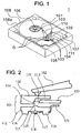
- FIG. 1 is a schematic diagram of an information recording apparatus employing a near-field optical head according to Embodiment 1.
- FIG. 1 shows an overview of an information recording apparatus employing a near-field optical head 101 according to Embodiment 1 of the invention.
- An information recording apparatus 1 of this embodiment includes, as shown in Fig. 1 , the near-field optical head 101, a suspension arm 102 that is movable in the parallel direction to a surface of a disk (magnetic recording medium) D, supports the near-field optical head 101 on the distal end side so that the near-field optical head 101 can rotate about two axes (which are an X-axis and a Y-axis) which are parallel to the surface of the disk D and are orthogonal to each other and brings the near-field optical head 101 closely to the disk D, a light control section 104 that stores a laser, not shown, that inputs a pencil of light from the proximal end side of an optical waveguide 103 to the optical waveguide 103, an actuator 105 that supports the proximal end side of the suspension arm 102 and scans and moves the suspension arm 102 in the X
- the disk D is a medium having a magnetic recording layer that records information based on the directions of magnetization (or with the inversion).
- the near-field optical head 101 When the disk D is rotated fast with the near-field optical head 101 close to the surface of the disk Dby several to several tens nm, the near-field optical head 101 always levitates in a predetermined attitude about the disk D.
- optical fiber is usedhere as the optical waveguide 103 having a path for propagating light
- an optical waveguide produced by patterning silicon oxide having a predetermined refractive index or an optical waveguide of resin may be used.
- the housing 108 has a square shape in the top view and contains a metallic material such as aluminum.
- the housing 108 has a concave 108a to accommodate each component internally.
- a lid, not shown, is removably fixed to the housing 108 to close the opening of the concave 108a.
- the motor 106 is attached at the substantial center of the concave 108a.
- the center hole of the disk D is fitted into the axis of the motor 106, and the disk D is removably fixed thereat.
- the actuator 105 is attached to a corner of the concave 108a.
- a carriage 110 is attached to the actuator 105 through a bearing 109.
- the suspension arm 102 is attached to the end of the carriage 110. Then, the carriage 110 and the suspension arm 102 are movable in the XY direction in response to the driving of the actuator 105.
- the carriage 110 and the suspension arm 102 withdraw from the upper part of the disk D in response to the driving of the actuator 105 when the disk D stops rotating.
- the light control section 104 is attached within the concave 108a adjacently to the actuator 105.
- a magnetic field control section 111 that controls the magnetic field generated from the near-field optical head 101 by a magnetic circuit, not shown, is placed adjacently to the light control section 104.
- the near-field optical head 101 has a minute opening, not shown, and generates near-field light through the minute opening from an input pencil of light. Near field light localizes in a much minuter space than the wavelength of emitted light from the laser and heats the minute area (predetermined area) on the surface of the disk D to temporarily reduce the coercivity of the area only. The near-field optical head 101 heats the minute area on the disk D with the near-field light, applies a magnetic field thereto and inverts the magnetization to record information.
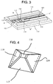
- Fig. 2 shows a section view of the near-field optical head 101 and the suspension arm 102 according to Embodiment 1 of the invention.
- the near-field optical head 101 has a double substrate structure having a mirror substrate 120 and a near-field optical element substrate 112, which are bonded together.
- the mirror substrate 120 has a V-groove 113 formed by performing anisotropic crystalline etching on an Si substrate.
- the V-groove 113 has one end extending to a side of the mirror substrate 120 and the other end extending to a mirror 114.
- the mirror 114 has an evaporated Al film to function as a light reflection surface.
- the optical waveguide 103 is a polarization maintaining optical fiber and is bonded and fixed to a predetermined position within the V-groove 113.
- the near-field optical element substrate 112 is shown as a result of the rotation by 90° within the substrate plane about the normal of the substrate.
- the near-field optical element substrate 112 contains quartz glass and has a microlens 115 on the top surface.
- the microlens 115 is an aspherical lens formed by etching with a gray scale mask.
- the bottom surface of the near-field optical element substrate 112 has an air-bearing surface 116 formed by etching.
- the air-bearing surface 116 is a surface having a tip (near-field light generating element) 117 and a reading tip (magnetic recording element) 122, which are formed to levitate by keeping a predetermined distance from the disk D by using the air-bearing force generated by the rotation of the disk D.
- the air-bearing surface 116 may be formed on the surface where the near-field optical element substrate 112 faces against the disk D, for example, among the surfaces of the near-field optical element substrate 112 and is provided in a rail shape at a position across the tip 117 and/or the reading tip 122.
- the bottom surface of the near-field optical element substrate 112 has the tip 117 in a square pyramid shape.
- the pointed end of the tip 117 has an optical minute opening 118.
- the tip 117 may have a shape other than the square pyramid and may have a cone or triangular pyramid shape.
- the bottom surface of the near-field optical element substrate 112 further has a magnetic pole 119.
- the magnetic pole 119 partially covers a side (sloped surface) of the tip 117.
- a wire 121 is connected to the near-field optical element substrate 112, and the wire 121 forms the coil wound about the magnetic pole 119, which provides an electromagnet as a whole.
- the light 131 output from the optical waveguide 103 is reflected by the mirror 114 and then passes through and is collected by the microlens 115 and, passes through the tip 117 and reaches the optical minute opening (magnetic pole gap) 118.
- the optical minute opening 118 is much minuter in size than the wavelength of the light from the laser and hardly allows normal propagated light to pass through, but near-field light is distributed in a short distance from the optical minute opening 118.
- the near-field light spreads as wide as the opening size of the optical minute opening 118 and localizes in a much minuter space than the original wavelength.
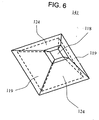
- Fig. 3 is an overview diagram of the bottom surface of the near-field optical head 101 according to Embodiment 1 of the invention.
- the bottom surface has the air-bearing surface 116 in a substantially rectangular parallelepiped shape, the tip 117, the magnetic pole 119, the wire 121 and the reading tip 122.
- the bottom surface of the reading tip 122 has a rectangular pyramid shape, and the two long sides are covered by a part of a magnetoresistive film 123.
- the magnetoresistive film 123 is patterned from the two sides of the reading tip 122 to the substrate surface. For clear illustration, the structure is shown in a different ratio from that of the actual dimensions.
- Fig. 4 is an enlarged view of the tip 117.
- the tip 117 has a square pyramid shape.
- the bottom surface of the tip 117 has sides about 20 ⁇ m long and is about 10 ⁇ m high.
- the two facing sides of the four sides of the tip 117 are covered by a part of the magnetic pole 119. Since the magnetic pole 119 does not allow light to pass through, the top surface of the tip 117 has the optical minute opening 118.
- Fig. 5 is a schematic diagram of a method of manufacturing the near-field optical head according to Embodiment 1 of the invention.
- the left column of the figure shows section views taken on the line A-A' in Fig. 3
- the right column shows section views taken on the line B-B'.
- the rows S1 to S4 show manufacturing steps.
- step S1 first of all, the tip 117, the air-bearing surface 116 and the reading tip 122 are produced by performing isotropic etching on the quartz glass substrate 112.
- the magnetic pole 119 is produced by a thin film deposition technique such as vapor deposition.
- the magnetic pole 119 only has a gap in the minute area of the top surface of the tip 117.
- step S3 After a film is deposited over the top surface, a structure is produced in which the magnetic pole film is removed from the top surface only by applying mechanical pressure thereto. Next in step S3, the magnetoresistive film 123 is deposited. Finally in step S4, the wire 121 is patterned.
- the three-dimensional structure of the tip 117, air-bearing surface 116 and reading tip 122 can be produced only by etching the quartz glass substrate 112.
- the near-field optical head 101 can be produced in high volume in a stable manner and at low costs.
- the near-field optical head 101 manufactured in this way functions as follows.
- the disk D is rotated at a high speed, and the near-field optical head 101 is brought closely to the surface.
- the air-bearing surface 116 receives air-bearing force from the air flowing above the surface of the disk D, and the near-field optical head 101 levitates from the surface of the disk D by a minute distance of several to several tens nm.
- the minute area on the surface of the disk D is heated by the near-field light occurring from the optical minute opening 118, and the coercivity of the area only is temporarily reduced.
- the current resulting from the modulation according to the information to be recorded is fed to the wire 121, and a magnetic flux is generated in the magnetic pole 119 by the current magnetic field.
- the magnetic pole 119 covers two sides of the tip 117 and has a magnetic pole gap at the part having the optical minute opening 118. Therefore, a magnetic leak field occurs from the optical minute opening 118.
- the near-field light from the optical minute opening 118 heats the minute area of the disk D, and, after the coercivity in the area is reduced, the direction of the magnetization is inverted by the action of the magnetic leak field. Thus, the information is recorded in the minute area. Since the magnetic leak field acts efficiently only on the minute area heated by near-field light, the control is also possible to perform the modulation on the laser in synchronization with the modulation on the current to the wire 121.
- the reading (reproduction) of the information from the disk D is performed by the same method as that for conventional magnetic heads and can be performed by measuring changes in resistance of the magnetoresistive film 123 deposited on the reading tip 122.
- optical minute opening 118 from which near-field light for locally heating the surface of the disk D occurs and the magnetic pole gap from which the magnetic leak field for locally inverting the magnetization of the surface of the disk D occurs share one same structure, information can be recorded in a minute area on the nanometer level with minimum amounts of incident light energy and current.
- the heating with near-field light and recording with a magnetic field are performed precisely at a same position by causing the near-field light at the same position as that of the magnetic leak field occurring from the tip top surface 118. Therefore, the minute area of the surface of the disk D can be magnetized only with the magnetic leak field from the tip top surface 118, which is defined by the size of the tip top surface 118 facing against the disk D, and a recording apparatus having a high density recording performance can be implemented. Since the tip 117 is applicable to both of the structure for causing near-field light and the structure for causing a magnetic leak field, the head based on the complex principle, near-field light assisted magnetic recording, can have the extremely simple structure, which is suitable for high-volume production at low costs.
- the integration of the tip 117 and the magnetic pole 119 allows easy manufacturing of the near-field optical head 101 without the fine alignment of the tip 117 and the magnetic pole 119. Since the optical minute opening 118 of the tip 117 is formed by the magnetic pole 119, the displacement between the irradiation areas to the disk D of the near-field light from the optical minute opening 118 and the magnetic field from the magnetic pole 119 can be suppressed, and the near-field light and the magnetic field can be irradiated to a substantially same area on the disk D. Thus, information can be recorded thereon in higher density than that of conventional cases.
- the section area of the tip 117 according to this embodiment which faces against the disk D and is orthogonal to the direction from one end to the other end, gradually increases.
- the distance between the magnetic pole 119 included in the tip 117 and the disk D increases, and the influence by the magnetic leak field decreases.
- the near-field optical head supporting high density recording can be implemented by suppressing the spread of the magnetic leak field.
- the air-bearing surface 116 is pushed up in the direction away from the disk D by the air levitating from the disk D with the rotation of the disk D.
- the air-bearing surface 116 can bring the tip 117 close to the disk D on the nanometer level. Therefore, both of the interaction between the near-field light and the surface of the disk D and the interaction between the magnetic field and the surface of the disk D can be implemented highly efficiently, and the recording in high density can be performed with a high S/N.
- recording and reproducing can be performed by one same head, and the near-field optical head suitable for a thin and compact recording apparatus can be implemented.
- the near-field light and the occurrence of the magnetic field can be modulated, and an information recording apparatus having a recording performance in high density can be implemented.
- Fig. 6 is an enlarged view of a tip 141 of a near-field optical head according to Embodiment 2 of the invention. Since the configuration of the entire information recording apparatus and the overview of the near-field optical head according to this embodiment are the same as those of Embodiment 1, the descriptions will be omitted herein.
- This embodiment is different from Embodiment 1 in that a side of the tip that causes near-field light and, at the same time, causes the magnetic leak field has an Au film 124.
- the Au film 124 is about 20 nm thick and is produced by vapor deposition.
- Fig. 7 is an enlarged view of the bottom surface of the near-field optical head according to Embodiment 3 of the invention.
- the descriptions on the same parts as those of Embodiment 1 will be omitted herein.
- This embodiment is different from Embodiment 1 in that the tip that causes near field light and that causes a magnetic leak field is a wedge tip 151.
- the wedge tip 151 has a side, which is longer several to several tens times than the longitudinal (or horizontal, in the figure) side orthogonal to the longer side, among the sides of the rectangular bottom surface.
- the light having a polarization direction 152 in the figure is input from the top surface of the head (or back face in the figure) to the tip in the above-described shape, like Embodiment 1, the light can reach the opening with less attenuation of the light.
- the caused near field light spreads long in the direction of the long side of the wedge tip and is distributed in an extremely localized manner in the direction of the short side. Recording in high density can be implemented by scanning recording bits on the surface of the disk D in the direction of the short side of the wedge tip.
- the near-field optical head includes two substrates of a substrate having a mirror and a substrate having a near-field optical element
- the invention is not limited to the heads in the structure.
- Fig. 8 shows a structure of a near-field optical head 161 including one substrate.
- a pointed end 114 of optical fiber 162 is processed diagonally by 45° and has a mirror. After light is reflected by the mirror, the light enters to the microlens 115 of the near-field optical head 161.
- the subsequent steps are the same as those of Embodiment 1.
- the light importing part of the near-field optical head can have various structures, which can implement information recording apparatus in ultrahigh density in combination with the structure of the invention.
- Fig. 9 is an enlarged view of a tip 170 of a near-field optical head according to Embodiment 3.
- the configuration of the entire information recording apparatus and the overview of the near-field optical head according to this embodiment are the same as those of Embodiment 2, and the descriptions therefore will be omitted herein.
- the magnetic field generated from a part 176 on the same plane as the tip top surface 118 of a first magnetic pole 171 is perpendicular to the surface of a disk D, not shown, and the return magnetic field from the surface of the disk D returns to a part 178 on the same plane of the tip top surface 118 of a second magnetic pole 172.
- a near-field optical head can be produced easily without finely aligning components of the near-field optical head.
Landscapes
- Physics & Mathematics (AREA)
- Engineering & Computer Science (AREA)
- Manufacturing & Machinery (AREA)
- Optics & Photonics (AREA)
- Electromagnetism (AREA)
- Magnetic Heads (AREA)
- Recording Or Reproducing By Magnetic Means (AREA)
- Adjustment Of The Magnetic Head Position Track Following On Tapes (AREA)
- Optical Head (AREA)
Abstract
Description
- The invention relates to a near-field optical head using near-field light having a resolution beyond the diffraction limit by localizing light to a minute area, and it particularly relates to a near-field optical head implementing an ultrahigh recording density by using both of near-field light and a magnetic field and an information recording apparatus including it.
- In order to respond the rapid increase of the amounts of image/motion picture information in the recent information society, information recording/reproducing apparatus have been increased in capacity and decreased in size. The density of an optical information recording/reproducing apparatus is increased by using light in a short wavelength since the recording density depends on the optical wavelength. The principle of recording and reproducing using near-field light has received attention as a method for implementing the density independent of wavelengths. In a magnetic information recording/reproducing apparatus, in order to separate and magnetize a minute area on the surface of a recording medium, the near-field light assisted magnetic recording that irradiates near-field light only to the minute area to heat and reduce the coercivity and then magnetizes the minute area is seen as a promising candidate of the next generation of the principle of recording and reproducing.
- A head of near-field light assisted magnetic recording has a conventional structure having a near-field light generating element adjacent to a recording magnetic pole of a magnetic head. The near-field light generating element has multiple planer metallic arms within an optical waveguide and has an opening at each of the distal ends (
JP-A-2005-515578 Pages 6 and 7,Fig. 2 ): Patent Document 1). The structure has been also proposed in which near-field light is generated at a position adjacent to a magnetic pole by installing a solid immersion lens on a flying head (JP-A-10-162444 - However, in the conventional near-field optical head in the structure having metallic arms within a waveguide, the near-field light generating element has a complicated structure within the waveguide, and it is difficult to form with high precision. In particular, it is extremely difficult to produce multiple metallic arms at different tilted angles within a waveguide produced as a thin film on a substrate.
- Since a processing technology is required for cutting out a magnetic recording element and a waveguide after producing them by using a thin-film producing technology and aligning the end surfaces of the waveguide and magnetic recording element on the nanometer level, there has been a problem that the manufacturing cost is high. For the structure employing a solid immersion lens, the lens and a magnetic recording element are produced separately and are then assembled. Therefore, the alignment must have high precision, and the high-volume production has been difficult.
- Furthermore, since the recording magnetic pole and the near-field light generating element are separate, the recording magnetic pole and the near-field light generating element must be placed with high precision. Otherwise, the magnetic field from the recording magnetic pole and the near-field light from the near-field light generating element cannot be directed to a desired position on a recording medium. Therefore, easy production of the head has not been allowed.
- Accordingly, the invention was made in view of the aforesaid points. It is an object of the invention to provide a near-field optical head which can be produced easily even without finely aligning components in the head and an information recording apparatus including the near-field optical head.
- In order to solve the problem, the substance of the first characteristic according to the invention is a near-field optical head that generates near-field light to heat a predetermined area of a medium and applies a magnetic field to the predetermined area to record information, the head including an optical waveguide having a path for propagating a pencil of light, and a near-field light generating element having a magnetic pole gap having an opening at the position facing against the predetermined area and collecting the pencil of light emitted from the optical waveguide and simultaneously propagating the collected pencil of light to the magnetic pole gap to generate the near-field light, wherein the magnetic pole gap is formed by a magnetic pole that applies a magnetic field to the predetermined area.
- The substance of the second characteristic according to the invention is that the near-field light generating element includes a pyramidal tip containing a transparent material, and the magnetic pole gap is formed at the pointed end of the pyramidal tip.
- The substance of the third characteristic according to the invention is that a part of the magnetic pole is provided at a part of a side of the pyramidal tip.
- The substance of the fourth characteristic according to the invention is that the head further includes a magnetic recording element having the magnetic pole and a coil that causes the magnetic pole to generate a magnetic field, wherein the near-field light generating element and the magnetic recording element are provided on a substantially flat-shaped substrate, the substrate has an air-bearing surface at the position where the substrate faces against the medium, and the air-bearing surface is formed such that the near-field light generating element and the magnetic recording element can levitate by keeping a predetermined distance from the surface of the medium by using the air-bearing force generated by the rotation of the medium.
- The substance of the fifth characteristic according to the invention is that the magnetic pole contains an opaque material.
- The substance of the sixth characteristic according to the invention is that a part of a side of the pyramidal tip has a metallic film.
- The substance of the seventh characteristic according to the invention is that the pyramidal tip has a quadrangular pyramid, and two facing sides of the four sides have a part of the magnetic pole.
- The substance of the eighth characteristic according to the invention is that the pyramidal tip has a quadrangular pyramid, and two facing sides of the four sides have a metallic film.
- The substance of the ninth characteristic according to the invention is that the near-field optical head further includes a magneto-resistive element that reads information recorded on the medium, wherein the magnetic tunnel junction is provided on the same substrate as that of the magnetic recording element.
- The substance of the tenth characteristic according to the invention is an information recording apparatus including a light source, a medium that records information with the inversion of magnetization, a near-field optical head having a near-field light generating element that receives light from the light source and generates near-field light from an optical minute opening, a motor that rotates the medium, a suspension arm that brings the near-field optical head closely to the medium, and an actuator that moves the suspension arm to a predetermined position of the medium, wherein the near-field optical head has a first magnetic pole and a second magnetic pole that faces against the first magnetic pole through a magnetic pole gap, and the near-field optical head heats a surface of the medium by generating the near-field light from the optical minute opening and records information on the medium by inverting the magnetization with the magnetic field generated within the magnetic pole gap between the first magnetic pole and the second magnetic pole.
- The substance of the eleventh characteristic according to the invention is that the near-field light generating element has a pyramidal tip containing a transparent material, and the magnetic pole gap is provided at the pointed end of the pyramidal tip.
- The substance of the twelfth characteristic according to the invention is that a part of the first magnetic pole and the second magnetic pole is provided on a part of a side of the pyramidal tip.
- The substance of the thirteenth characteristic according to the invention is that the information recording apparatus further includes a light control section that controls the intensity of light from the light source, a magnetic field control section that controls the magnetic field generated from the magnetic pole gap and an apparatus control section that simultaneously performs modulation on the light control section and the magnetic field control section.
- The substance of the fourteenth characteristic according to the invention is that the direction of the magnetization is substantially parallel to the surface of the medium.
- The substance of the fifteenth characteristic according to the invention is that the direction of the magnetization is substantially perpendicular to the surface of the medium.
- [
Fig. 1] Fig. 1 is a schematic diagram of an information recording apparatus employing a near-field optical head according toEmbodiment 1. - [
Fig. 2] Fig. 2 is asectionviewof thenear-fieldoptical head according toEmbodiment 1 and a suspension arm. - [
Fig. 3] Fig. 3 is an overview diagram of the bottom surface of the near-field optical head according toEmbodiment 1. - [
Fig. 4] Fig. 4 is an enlarged view of a tip. - [
Fig. 5] Fig. 5 is a schematic flowchart showing a method of manufacturing the near-field optical head according toEmbodiment 1. - [
Fig. 6] Fig. 6 is an enlarged view of the tip of a near-field optical head according to Embodiment 2. - [
Fig. 7] Fig. 7 is an overview diagram of the bottom surface of a near-field optical head according to Embodiment 3. - [
Fig. 8] Fig. 8 is a structure diagram of a near-field head including one substrate. - [
Fig. 9] Fig. 9 is an enlarged view of the tip of the near-field optical head according to Embodiment 3. -
Fig. 1 shows an overview of an information recording apparatus employing a near-fieldoptical head 101 according toEmbodiment 1 of the invention. Aninformation recording apparatus 1 of this embodiment includes, as shown inFig. 1 , the near-fieldoptical head 101, asuspension arm 102 that is movable in the parallel direction to a surface of a disk (magnetic recording medium) D, supports the near-fieldoptical head 101 on the distal end side so that the near-fieldoptical head 101 can rotate about two axes (which are an X-axis and a Y-axis) which are parallel to the surface of the disk D and are orthogonal to each other and brings the near-fieldoptical head 101 closely to the disk D, alight control section 104 that stores a laser, not shown, that inputs a pencil of light from the proximal end side of anoptical waveguide 103 to theoptical waveguide 103, an actuator 105 that supports the proximal end side of thesuspension arm 102 and scans and moves thesuspension arm 102 in the XY directions, which are parallel to the surface of the disk D, a motor (rotation driving unit) 106 that rotates the diskDinapredetermineddirection, anapparatus control section 107 that supplies the current modulated according to information to the near-fieldoptical head 101 and controls an operation of thelight control section 104, and ahousing 108 that internally stores those components. The pencil of light to theoptical waveguide 103 can be modulated in intensity by thelight control section 104 as required. - The disk D is a medium having a magnetic recording layer that records information based on the directions of magnetization (or with the inversion). When the disk D is rotated fast with the near-field
optical head 101 close to the surface of the disk Dby several to several tens nm, the near-fieldoptical head 101 always levitates in a predetermined attitude about the disk D. While optical fiber is usedhere as theoptical waveguide 103 having a path for propagating light, an optical waveguide produced by patterning silicon oxide having a predetermined refractive index or an optical waveguide of resin may be used. - The
housing 108 has a square shape in the top view and contains a metallic material such as aluminum. Thehousing 108 has a concave 108a to accommodate each component internally. A lid, not shown, is removably fixed to thehousing 108 to close the opening of the concave 108a. - The
motor 106 is attached at the substantial center of the concave 108a. The center hole of the disk D is fitted into the axis of themotor 106, and the disk D is removably fixed thereat. The actuator 105 is attached to a corner of the concave 108a. Acarriage 110 is attached to the actuator 105 through abearing 109. Thesuspension arm 102 is attached to the end of thecarriage 110. Then, thecarriage 110 and thesuspension arm 102 are movable in the XY direction in response to the driving of the actuator 105. - The
carriage 110 and thesuspension arm 102 withdraw from the upper part of the disk D in response to the driving of the actuator 105 when the disk D stops rotating. Thelight control section 104 is attached within the concave 108a adjacently to the actuator 105. A magneticfield control section 111 that controls the magnetic field generated from the near-fieldoptical head 101 by a magnetic circuit, not shown, is placed adjacently to thelight control section 104. - The near-field
optical head 101 has a minute opening, not shown, and generates near-field light through the minute opening from an input pencil of light. Near field light localizes in a much minuter space than the wavelength of emitted light from the laser and heats the minute area (predetermined area) on the surface of the disk D to temporarily reduce the coercivity of the area only. The near-fieldoptical head 101 heats the minute area on the disk D with the near-field light, applies a magnetic field thereto and inverts the magnetization to record information. -
Fig. 2 shows a section view of the near-fieldoptical head 101 and thesuspension arm 102 according toEmbodiment 1 of the invention. The near-fieldoptical head 101 has a double substrate structure having amirror substrate 120 and a near-fieldoptical element substrate 112, which are bonded together. Themirror substrate 120 has a V-groove 113 formed by performing anisotropic crystalline etching on an Si substrate. - The V-
groove 113 has one end extending to a side of themirror substrate 120 and the other end extending to amirror 114. Themirror 114 has an evaporated Al film to function as a light reflection surface. Theoptical waveguide 103 is a polarization maintaining optical fiber and is bonded and fixed to a predetermined position within the V-groove 113. For easy description, the near-fieldoptical element substrate 112 is shown as a result of the rotation by 90° within the substrate plane about the normal of the substrate. The near-fieldoptical element substrate 112 contains quartz glass and has amicrolens 115 on the top surface. - The
microlens 115 is an aspherical lens formed by etching with a gray scale mask. The bottom surface of the near-fieldoptical element substrate 112 has an air-bearingsurface 116 formed by etching. - The air-bearing
surface 116 is a surface having a tip (near-field light generating element) 117 and a reading tip (magnetic recording element) 122, which are formed to levitate by keeping a predetermined distance from the disk D by using the air-bearing force generated by the rotation of the disk D. - According to this embodiment, the air-bearing
surface 116 may be formed on the surface where the near-fieldoptical element substrate 112 faces against the disk D, for example, among the surfaces of the near-fieldoptical element substrate 112 and is provided in a rail shape at a position across thetip 117 and/or thereading tip 122. - The bottom surface of the near-field
optical element substrate 112 has thetip 117 in a square pyramid shape. The pointed end of thetip 117 has anoptical minute opening 118. Thetip 117 may have a shape other than the square pyramid and may have a cone or triangular pyramid shape. The bottom surface of the near-fieldoptical element substrate 112 further has amagnetic pole 119. Themagnetic pole 119 partially covers a side (sloped surface) of thetip 117. Awire 121 is connected to the near-fieldoptical element substrate 112, and thewire 121 forms the coil wound about themagnetic pole 119, which provides an electromagnet as a whole. - The light 131 output from the
optical waveguide 103 is reflected by themirror 114 and then passes through and is collected by themicrolens 115 and, passes through thetip 117 and reaches the optical minute opening (magnetic pole gap) 118. Theoptical minute opening 118 is much minuter in size than the wavelength of the light from the laser and hardly allows normal propagated light to pass through, but near-field light is distributed in a short distance from theoptical minute opening 118. The near-field light spreads as wide as the opening size of theoptical minute opening 118 and localizes in a much minuter space than the original wavelength. -
Fig. 3 is an overview diagram of the bottom surface of the near-fieldoptical head 101 according toEmbodiment 1 of the invention. The bottom surface has the air-bearingsurface 116 in a substantially rectangular parallelepiped shape, thetip 117, themagnetic pole 119, thewire 121 and thereading tip 122. - The bottom surface of the
reading tip 122 has a rectangular pyramid shape, and the two long sides are covered by a part of amagnetoresistive film 123. Themagnetoresistive film 123 is patterned from the two sides of thereading tip 122 to the substrate surface. For clear illustration, the structure is shown in a different ratio from that of the actual dimensions. -
Fig. 4 is an enlarged view of thetip 117. Thetip 117 has a square pyramid shape. The bottom surface of thetip 117 has sides about 20 µm long and is about 10 µm high. The two facing sides of the four sides of thetip 117 are covered by a part of themagnetic pole 119. Since themagnetic pole 119 does not allow light to pass through, the top surface of thetip 117 has theoptical minute opening 118. -
Fig. 5 is a schematic diagram of a method of manufacturing the near-field optical head according toEmbodiment 1 of the invention. The left column of the figure shows section views taken on the line A-A' inFig. 3 , and the right column shows section views taken on the line B-B'. The rows S1 to S4 show manufacturing steps. In step S1 first of all, thetip 117, the air-bearingsurface 116 and thereading tip 122 are produced by performing isotropic etching on thequartz glass substrate 112. Next in step S2, themagnetic pole 119 is produced by a thin film deposition technique such as vapor deposition. Themagnetic pole 119 only has a gap in the minute area of the top surface of thetip 117. After a film is deposited over the top surface, a structure is produced in which the magnetic pole film is removed from the top surface only by applying mechanical pressure thereto. Next in step S3, themagnetoresistive film 123 is deposited. Finally in step S4, thewire 121 is patterned. - In this manufacturing method according to the invention, the three-dimensional structure of the
tip 117, air-bearingsurface 116 and readingtip 122 can be produced only by etching thequartz glass substrate 112. Thus, the near-fieldoptical head 101 can be produced in high volume in a stable manner and at low costs. - The near-field
optical head 101 manufactured in this way functions as follows. The disk D is rotated at a high speed, and the near-fieldoptical head 101 is brought closely to the surface. Thus, the air-bearingsurface 116 receives air-bearing force from the air flowing above the surface of the disk D, and the near-fieldoptical head 101 levitates from the surface of the disk D by a minute distance of several to several tens nm. The minute area on the surface of the disk D is heated by the near-field light occurring from theoptical minute opening 118, and the coercivity of the area only is temporarily reduced. The current resulting from the modulation according to the information to be recorded is fed to thewire 121, and a magnetic flux is generated in themagnetic pole 119 by the current magnetic field. Themagnetic pole 119 covers two sides of thetip 117 and has a magnetic pole gap at the part having theoptical minute opening 118. Therefore, a magnetic leak field occurs from theoptical minute opening 118. - The near-field light from the optical minute opening 118 heats the minute area of the disk D, and, after the coercivity in the area is reduced, the direction of the magnetization is inverted by the action of the magnetic leak field. Thus, the information is recorded in the minute area. Since the magnetic leak field acts efficiently only on the minute area heated by near-field light, the control is also possible to perform the modulation on the laser in synchronization with the modulation on the current to the
wire 121. - The reading (reproduction) of the information from the disk D is performed by the same method as that for conventional magnetic heads and can be performed by measuring changes in resistance of the
magnetoresistive film 123 deposited on thereading tip 122. - Since the optical minute opening 118 from which near-field light for locally heating the surface of the disk D occurs and the magnetic pole gap from which the magnetic leak field for locally inverting the magnetization of the surface of the disk D occurs share one same structure, information can be recorded in a minute area on the nanometer level with minimum amounts of incident light energy and current.
- More specifically, the heating with near-field light and recording with a magnetic field are performed precisely at a same position by causing the near-field light at the same position as that of the magnetic leak field occurring from the tip
top surface 118. Therefore, the minute area of the surface of the disk D can be magnetized only with the magnetic leak field from the tiptop surface 118, which is defined by the size of the tiptop surface 118 facing against the disk D, and a recording apparatus having a high density recording performance can be implemented.
Since thetip 117 is applicable to both of the structure for causing near-field light and the structure for causing a magnetic leak field, the head based on the complex principle, near-field light assisted magnetic recording, can have the extremely simple structure, which is suitable for high-volume production at low costs. - In other words, according to the invention, the integration of the
tip 117 and themagnetic pole 119 allows easy manufacturing of the near-fieldoptical head 101 without the fine alignment of thetip 117 and themagnetic pole 119. Since the optical minute opening 118 of thetip 117 is formed by themagnetic pole 119, the displacement between the irradiation areas to the disk D of the near-field light from theoptical minute opening 118 and the magnetic field from themagnetic pole 119 can be suppressed, and the near-field light and the magnetic field can be irradiated to a substantially same area on the disk D. Thus, information can be recorded thereon in higher density than that of conventional cases. - Particularly, the section area of the
tip 117 according to this embodiment, which faces against the disk D and is orthogonal to the direction from one end to the other end, gradually increases. Thus, from the tiptop surface 118, which is the one end, to the other end, the distance between themagnetic pole 119 included in thetip 117 and the disk D increases, and the influence by the magnetic leak field decreases. - Therefore, recording is only performed with the magnetic leak field from the part on the same plane as that of the tip
top surface 118 of themagnetic pole 119. Furthermore, since the sides of thetip 117 is apart from the disk D, the magnetic leak field reaching the surface of the disk D is extremely small, and the influence on the recording operation is ignorable. In this way, the near-field optical head supporting high density recording can be implemented by suppressing the spread of the magnetic leak field. - According to the invention, the air-bearing
surface 116 is pushed up in the direction away from the disk D by the air levitating from the disk D with the rotation of the disk D. Thus, only providing the air-bearingsurface 116 can bring thetip 117 close to the disk D on the nanometer level. Therefore, both of the interaction between the near-field light and the surface of the disk D and the interaction between the magnetic field and the surface of the disk D can be implemented highly efficiently, and the recording in high density can be performed with a high S/N. - Furthermore, according to the invention, recording and reproducing can be performed by one same head, and the near-field optical head suitable for a thin and compact recording apparatus can be implemented.
- According to the invention, by synchronizing the occurrence of the near-field light and the occurrence of the magnetic field, they can be modulated, and an information recording apparatus having a recording performance in high density can be implemented.
-
Fig. 6 is an enlarged view of atip 141 of a near-field optical head according to Embodiment 2 of the invention. Since the configuration of the entire information recording apparatus and the overview of the near-field optical head according to this embodiment are the same as those ofEmbodiment 1, the descriptions will be omitted herein. This embodiment is different fromEmbodiment 1 in that a side of the tip that causes near-field light and, at the same time, causes the magnetic leak field has anAu film 124. TheAu film 124 is about 20 nm thick and is produced by vapor deposition. - With the characteristic, since both of the
magnetic pole 119 and theAu film 124 do not allow light to pass through, near-field light occurs only from theoptical minute opening 118, and light can be more localized thanEmbodiment 1.
Since the incident light excites plasmon on the surface of theAu film 124, extremely strong near field light can be generated, and a minute area on the disk D can be rapidly heated in a short period of time. By using the near-field optical head having thetip 141 in the structure as described above, recording/reproduction in ultrahigh density can be implemented with a high S/N. -
Fig. 7 is an enlarged view of the bottom surface of the near-field optical head according to Embodiment 3 of the invention. The descriptions on the same parts as those ofEmbodiment 1 will be omitted herein. This embodiment is different fromEmbodiment 1 in that the tip that causes near field light and that causes a magnetic leak field is awedge tip 151. Thewedge tip 151 has a side, which is longer several to several tens times than the longitudinal (or horizontal, in the figure) side orthogonal to the longer side, among the sides of the rectangular bottom surface. When the light having apolarization direction 152 in the figure is input from the top surface of the head (or back face in the figure) to the tip in the above-described shape, likeEmbodiment 1, the light can reach the opening with less attenuation of the light. The caused near field light spreads long in the direction of the long side of the wedge tip and is distributed in an extremely localized manner in the direction of the short side. Recording in high density can be implemented by scanning recording bits on the surface of the disk D in the direction of the short side of the wedge tip. - Having described the embodiments up to this point in that the near-field optical head includes two substrates of a substrate having a mirror and a substrate having a near-field optical element, the invention is not limited to the heads in the structure. For example,
Fig. 8 shows a structure of a near-fieldoptical head 161 including one substrate. The same reference numerals are given to the same components of those of the embodiments described up to this point, and the descriptions will be omitted herein. In this example, apointed end 114 ofoptical fiber 162 is processed diagonally by 45° and has a mirror. After light is reflected by the mirror, the light enters to themicrolens 115 of the near-fieldoptical head 161. The subsequent steps are the same as those ofEmbodiment 1. In this way, the light importing part of the near-field optical head can have various structures, which can implement information recording apparatus in ultrahigh density in combination with the structure of the invention. -
Fig. 9 is an enlarged view of atip 170 of a near-field optical head according to Embodiment 3. The configuration of the entire information recording apparatus and the overview of the near-field optical head according to this embodiment are the same as those of Embodiment 2, and the descriptions therefore will be omitted herein. According to this embodiment, the magnetic field generated from apart 176 on the same plane as the tiptop surface 118 of a firstmagnetic pole 171 is perpendicular to the surface of a disk D, not shown, and the return magnetic field from the surface of the disk D returns to apart 178 on the same plane of the tiptop surface 118 of a secondmagnetic pole 172. Thus, recording by the magnetization in the vertical direction on the surface of the disk D, that is, perpendicular recording is implemented. Since apart 175 on a side of the tip of the firstmagnetic pole 171 and apart 177 in a side of the tip of the secondmagnetic pole 172 are away from the surface of the disk D, the influence on the recording operation is ignorable. In the perpendicular recording, the size of the part contributing to the recording in the firstmagnetic pole 171 must be minute for recording in high density. According to the invention however, since the firstmagnetic pole 171 is provided on a side of a pyramidal tip, the recording density is defined by the size of thepart 176 on the same plane of the tiptop surface 118. Thus, information recording apparatus in ultrahigh density can be implemented. - According to the invention, a near-field optical head can be produced easily without finely aligning components of the near-field optical head.
Claims (15)
- Anear-field optical head that.generates near-field light to heat a predetermined area of a medium and applies a magnetic field to the predetermined area to record information, the head comprising:an optical waveguide having a path for propagating a pencil of light; anda near-field light generating element having a magnetic pole gap having an opening at the position facing against the predetermined area and collecting the pencil of light emitted from the optical waveguide and simultaneously propagating the collected pencil of light to the magnetic pole gap to generate the near-field light,wherein the magnetic pole gap is formed by a magnetic pole that applies a magnetic field to the predetermined area.
- The near-field optical head according to Claim 1, wherein the near-field light generating element includes a pyramidal tip containing a transparent material, and the magnetic pole gap is formed at the pointed end of the pyramidal tip.
- The near-field optical head according to Claim 2, wherein a part of the magnetic pole is provided at a part of a side of the pyramidal tip.
- The near-field optical head according to Claim 1, the head further comprising a magnetic recording element having the magnetic pole and a coil that causes the magnetic pole to generate a magnetic field, wherein the near-field light generating element and the magnetic recording element are provided on a substantially flat-shaped substrate, the substrate has an air-bearing surface at the position where the substrate faces against the medium, and the air-bearing surface is formed such that the near-field light generating element and the magnetic recording element can levitate by keeping a predetermined distance from the surface of the medium by using the air-bearing force generated by the rotation of the medium.
- The near-field optical head according to Claim 1, wherein the magnetic pole contains an opaque material.
- The near-field optical head according to Claim 2, wherein a part of a side of the pyramidal tip has a metallic film.
- The near-field optical head according to Claim 3, wherein the pyramidal tip has a quadrangular pyramid, and two facing sides of the four sides have a part of the magnetic pole.
- The near-field optical head according to Claim 2, wherein the pyramidal tip has a quadrangular pyramid, and two facing sides of the four sides have a metallic film.
- The near-field optical head according to Claim 4, further comprising a magneto-resistive element that reads information recorded on the medium,
wherein the magnetic tunnel junction is provided on the same substrate as that of the magnetic recording element. - An information recording apparatus comprising a light source, a medium that records information with the inversion of magnetization, a near-field optical head having a near-field light generating element that receives light from the light source and generates near-field light from an optical minute opening, a motor that rotates the medium, a suspension arm that brings the near-field optical head closely to the medium, and an actuator that moves the suspension arm to a predetermined position of the medium,
wherein the near-field optical head has a first magnetic pole and a second magnetic pole that faces against the first magnetic pole through a magnetic pole gap; and
the near-field optical head heats a surface of the medium by generating the near-field light from the optical minute opening and records information on the medium by inverting the magnetization with the magnetic field generated within the magnetic pole gap between the first magnetic pole and the second magnetic pole. - The information recording apparatus according to Claim 10, wherein the near-field light generating element has a pyramidal tip containing a transparent material, and the magnetic pole gap is provided at the pointed end of the pyramidal tip.
- The information recording apparatus according to Claim 11, wherein a part of the first magnetic pole and the second magnetic pole is provided on a part of a side of the pyramidal tip.
- The information recording apparatus according to Claim 10, the apparatus further comprising a light control section that controls the intensity of light from the light source, a magnetic field control section that controls the magnetic field generated from the magnetic pole gap and an apparatus control section that simultaneously performs modulation on the light control section and the magnetic field control section.
- The information recording apparatus according to Claim 10, wherein the direction of the magnetization is substantially parallel to the surface of the medium.
- The information recording apparatus according to Claim 10, wherein the direction of the magnetization is substantially perpendicular to the surface of the medium.
Applications Claiming Priority (2)
| Application Number | Priority Date | Filing Date | Title |
|---|---|---|---|
| JP2005377737 | 2005-12-28 | ||
| PCT/JP2006/324899 WO2007074650A1 (en) | 2005-12-28 | 2006-12-14 | Head using near-field light and information recorder |
Publications (2)
| Publication Number | Publication Date |
|---|---|
| EP1970903A1 true EP1970903A1 (en) | 2008-09-17 |
| EP1970903A4 EP1970903A4 (en) | 2009-08-05 |
Family
ID=38217871
Family Applications (1)
| Application Number | Title | Priority Date | Filing Date |
|---|---|---|---|
| EP06834653A Ceased EP1970903A4 (en) | 2005-12-28 | 2006-12-14 | HEAD EMPLOYING NEAR FIELD LIGHT AND INFORMATION RECORDER |
Country Status (4)
| Country | Link |
|---|---|
| US (1) | US8023366B2 (en) |
| EP (1) | EP1970903A4 (en) |
| JP (2) | JP5060961B2 (en) |
| WO (1) | WO2007074650A1 (en) |
Families Citing this family (6)
| Publication number | Priority date | Publication date | Assignee | Title |
|---|---|---|---|---|
| US7869309B2 (en) * | 2005-08-11 | 2011-01-11 | Seagate Technology Llc | Dual wire integrated WAMR/HAMR writing head |
| JP4673263B2 (en) * | 2006-07-24 | 2011-04-20 | セイコーインスツル株式会社 | Near-field light assisted magnetic recording head and recording apparatus using the same |
| JP5841313B2 (en) | 2007-07-10 | 2016-01-13 | セイコーインスツル株式会社 | Near-field optical head and information recording / reproducing apparatus |
| US8050170B2 (en) * | 2007-10-04 | 2011-11-01 | Seiko Instruments Inc. | Near field optical head and information recording and reproducing device |
| JP4462346B2 (en) | 2007-12-28 | 2010-05-12 | Tdk株式会社 | Thermally assisted magnetic head |
| CN114660515B (en) * | 2020-12-22 | 2025-07-22 | 财团法人工业技术研究院 | Magnetic field structure |
Family Cites Families (14)
| Publication number | Priority date | Publication date | Assignee | Title |
|---|---|---|---|---|
| FR2741470B1 (en) * | 1995-11-22 | 1998-01-02 | Commissariat Energie Atomique | METHOD FOR PRODUCING A PLANAR MAGNETIC HEAD AND HEAD OBTAINED BY THIS PROCESS |
| JP3895458B2 (en) * | 1998-04-08 | 2007-03-22 | セイコーインスツル株式会社 | Near-field optical head |
| JP3366582B2 (en) * | 1998-12-17 | 2003-01-14 | シャープ株式会社 | Thin film magnetic head and method of manufacturing the same |
| JP2000187877A (en) * | 1998-12-24 | 2000-07-04 | Sharp Corp | Optical waveguide element and waveguide optical head |
| EP1184861B1 (en) * | 1999-05-31 | 2009-07-15 | Fujitsu Limited | Recording head, method of manufacturing recording head, and information recording device |
| JP3903365B2 (en) * | 2001-03-29 | 2007-04-11 | 株式会社東芝 | Optically assisted magnetic recording head and optically assisted magnetic recording apparatus |
| JP2003045004A (en) * | 2001-07-27 | 2003-02-14 | Fuji Xerox Co Ltd | Optical assist magnetic head and optical assist magnetic disk device |
| US6975580B2 (en) * | 2001-12-18 | 2005-12-13 | Interntional Business Machines Corporation | Optical aperture for data recording having transmission enhanced by waveguide mode resonance |
| US7106935B2 (en) * | 2002-01-07 | 2006-09-12 | Seagate Technology Llc | Apparatus for focusing plasmon waves |
| JP2003228802A (en) * | 2002-02-01 | 2003-08-15 | Fuji Xerox Co Ltd | Light-assisted magnetic recording head and light-assisted magnetic recording disk unit |
| JP3948318B2 (en) * | 2002-03-12 | 2007-07-25 | 富士ゼロックス株式会社 | Optically assisted magnetic recording head and optically assisted magnetic recording disk device |
| JP3984568B2 (en) * | 2003-06-12 | 2007-10-03 | 株式会社日立製作所 | Magnetic recording apparatus and magnetic recording method |
| JP2008269757A (en) * | 2007-03-27 | 2008-11-06 | Seiko Instruments Inc | Near-field optical head and information recording / reproducing apparatus |
| US8050170B2 (en) * | 2007-10-04 | 2011-11-01 | Seiko Instruments Inc. | Near field optical head and information recording and reproducing device |
-
2006
- 2006-12-14 JP JP2007551896A patent/JP5060961B2/en not_active Expired - Fee Related
- 2006-12-14 WO PCT/JP2006/324899 patent/WO2007074650A1/en not_active Ceased
- 2006-12-14 EP EP06834653A patent/EP1970903A4/en not_active Ceased
- 2006-12-14 US US12/087,073 patent/US8023366B2/en not_active Expired - Fee Related
-
2012
- 2012-05-16 JP JP2012112738A patent/JP2012190536A/en not_active Withdrawn
Also Published As
| Publication number | Publication date |
|---|---|
| JP2012190536A (en) | 2012-10-04 |
| JP5060961B2 (en) | 2012-10-31 |
| US20090028007A1 (en) | 2009-01-29 |
| EP1970903A4 (en) | 2009-08-05 |
| JPWO2007074650A1 (en) | 2009-06-04 |
| WO2007074650A1 (en) | 2007-07-05 |
| US8023366B2 (en) | 2011-09-20 |
Similar Documents
| Publication | Publication Date | Title |
|---|---|---|
| US20040062152A1 (en) | Device for writing data to a recording medium and method of fabricating same | |
| JP5201571B2 (en) | Recording head and information recording / reproducing apparatus | |
| JP2013101748A (en) | Near-field light generation element, near-field optical head and information recording and reproducing apparatus | |
| US8050170B2 (en) | Near field optical head and information recording and reproducing device | |
| JP4024570B2 (en) | Near-field light generating element, near-field light recording device, and near-field light microscope | |
| JP4482485B2 (en) | Head module | |
| JP5841313B2 (en) | Near-field optical head and information recording / reproducing apparatus | |
| JP2012190536A (en) | Near-field light using head and information recording device | |
| JP4601867B2 (en) | Near-field optical head | |
| JP2006053978A (en) | Near-field optical head and information reproducing apparatus using the near-field optical head | |
| US8054714B2 (en) | Near field light assisted magnetic recording head and recording apparatus using the same | |
| JP5943417B2 (en) | Near-field light generating element, near-field light head, and information recording / reproducing apparatus | |
| US8284636B2 (en) | Near-field thermally assisted magnetic recording head and recording apparatus thereof | |
| JP2007109269A (en) | Near-field light head | |
| JP4850017B2 (en) | Manufacturing method of near-field optical head | |
| JP5200273B2 (en) | Head gimbal assembly and information recording / reproducing apparatus including the same | |
| JP5854403B2 (en) | Near-field optical head, method for manufacturing near-field optical head, and information recording / reproducing apparatus | |
| JP5597000B2 (en) | Recording flexure, head gimbal assembly including the same, and manufacturing method of recording flexure | |
| WO2008062677A1 (en) | Recording head and information recording/reproducing device | |
| JP2010123226A (en) | Near field light head and information recording and reproducing device | |
| WO2009154043A1 (en) | Head gimbal assembly with optical guide structure, and information recording/reproducing device | |
| JP2009295205A (en) | Information recording/reproducing device | |
| JP2010272195A (en) | Recording head and recording head manufacturing method | |
| JP2009099212A (en) | Recording head and information recording / reproducing apparatus |
Legal Events
| Date | Code | Title | Description |
|---|---|---|---|
| PUAI | Public reference made under article 153(3) epc to a published international application that has entered the european phase |
Free format text: ORIGINAL CODE: 0009012 |
|
| 17P | Request for examination filed |
Effective date: 20080714 |
|
| AK | Designated contracting states |
Kind code of ref document: A1 Designated state(s): DE FR GB |
|
| RBV | Designated contracting states (corrected) |
Designated state(s): DE FR GB |
|
| A4 | Supplementary search report drawn up and despatched |
Effective date: 20090702 |
|
| 17Q | First examination report despatched |
Effective date: 20091021 |
|
| DAX | Request for extension of the european patent (deleted) | ||
| REG | Reference to a national code |
Ref country code: DE Ref legal event code: R003 |
|
| STAA | Information on the status of an ep patent application or granted ep patent |
Free format text: STATUS: THE APPLICATION HAS BEEN REFUSED |
|
| 18R | Application refused |
Effective date: 20121123 |