EP1970522A2 - Cabinetwork for windows and doors or the like, and insert element applied in such cabinetwork - Google Patents
Cabinetwork for windows and doors or the like, and insert element applied in such cabinetwork Download PDFInfo
- Publication number
- EP1970522A2 EP1970522A2 EP08003647A EP08003647A EP1970522A2 EP 1970522 A2 EP1970522 A2 EP 1970522A2 EP 08003647 A EP08003647 A EP 08003647A EP 08003647 A EP08003647 A EP 08003647A EP 1970522 A2 EP1970522 A2 EP 1970522A2
- Authority
- EP
- European Patent Office
- Prior art keywords
- insert element
- cabinetwork
- fire
- retardant
- mentioned
- Prior art date
- Legal status (The legal status is an assumption and is not a legal conclusion. Google has not performed a legal analysis and makes no representation as to the accuracy of the status listed.)
- Granted
Links
- 239000000463 material Substances 0.000 claims abstract description 36
- 239000003063 flame retardant Substances 0.000 claims abstract description 31
- XLYOFNOQVPJJNP-UHFFFAOYSA-N water Substances O XLYOFNOQVPJJNP-UHFFFAOYSA-N 0.000 claims abstract description 6
- 230000008020 evaporation Effects 0.000 claims abstract description 4
- 238000001704 evaporation Methods 0.000 claims abstract description 4
- XAGFODPZIPBFFR-UHFFFAOYSA-N aluminium Chemical compound [Al] XAGFODPZIPBFFR-UHFFFAOYSA-N 0.000 description 3
- 229910052782 aluminium Inorganic materials 0.000 description 3
- 239000004411 aluminium Substances 0.000 description 3
- 238000010276 construction Methods 0.000 description 3
- 238000004026 adhesive bonding Methods 0.000 description 2
- 239000000203 mixture Substances 0.000 description 2
- 229910052602 gypsum Inorganic materials 0.000 description 1
- 239000010440 gypsum Substances 0.000 description 1
- 239000011796 hollow space material Substances 0.000 description 1
- 239000011810 insulating material Substances 0.000 description 1
- 239000000843 powder Substances 0.000 description 1
Images

Classifications
-
- E—FIXED CONSTRUCTIONS
- E06—DOORS, WINDOWS, SHUTTERS, OR ROLLER BLINDS IN GENERAL; LADDERS
- E06B—FIXED OR MOVABLE CLOSURES FOR OPENINGS IN BUILDINGS, VEHICLES, FENCES OR LIKE ENCLOSURES IN GENERAL, e.g. DOORS, WINDOWS, BLINDS, GATES
- E06B3/00—Window sashes, door leaves, or like elements for closing wall or like openings; Layout of fixed or moving closures, e.g. windows in wall or like openings; Features of rigidly-mounted outer frames relating to the mounting of wing frames
- E06B3/96—Corner joints or edge joints for windows, doors, or the like frames or wings
-
- E—FIXED CONSTRUCTIONS
- E06—DOORS, WINDOWS, SHUTTERS, OR ROLLER BLINDS IN GENERAL; LADDERS
- E06B—FIXED OR MOVABLE CLOSURES FOR OPENINGS IN BUILDINGS, VEHICLES, FENCES OR LIKE ENCLOSURES IN GENERAL, e.g. DOORS, WINDOWS, BLINDS, GATES
- E06B5/00—Doors, windows, or like closures for special purposes; Border constructions therefor
- E06B5/10—Doors, windows, or like closures for special purposes; Border constructions therefor for protection against air-raid or other war-like action; for other protective purposes
- E06B5/16—Fireproof doors or similar closures; Adaptations of fixed constructions therefor
- E06B5/161—Profile members therefor
-
- E—FIXED CONSTRUCTIONS
- E06—DOORS, WINDOWS, SHUTTERS, OR ROLLER BLINDS IN GENERAL; LADDERS
- E06B—FIXED OR MOVABLE CLOSURES FOR OPENINGS IN BUILDINGS, VEHICLES, FENCES OR LIKE ENCLOSURES IN GENERAL, e.g. DOORS, WINDOWS, BLINDS, GATES
- E06B3/00—Window sashes, door leaves, or like elements for closing wall or like openings; Layout of fixed or moving closures, e.g. windows in wall or like openings; Features of rigidly-mounted outer frames relating to the mounting of wing frames
- E06B3/70—Door leaves
- E06B2003/7059—Specific frame characteristics
- E06B2003/7074—Metal frames
- E06B2003/7078—Metal frames with fire retardant measures in frame
Definitions
- the present invention concerns cabinetwork for windows, doors or the like, which cabinetwork is provided with a number of struts connecting to one another.
- Fixing the legs of the insert element in the respective hollow far ends of the struts is done, as is known, for example by clamping them in the struts by means of strut lips that are pressed inward and that push against said insert element, or by screwing the insert element in the struts.
- a disadvantage of the known cabinetworks is that, because of the presence of the above-mentioned insert element at the links between the struts, it is not possible to provide any fire-retardant material in these links, such that the temperature at the insert elements will increase too strongly in case of fire, and the fire safety is no longer guaranteed.
- the present invention aims to remedy one or several of the above-mentioned and other disadvantages.
- the present invention concerns a cabinetwork for windows, doors or the like, which cabinetwork is provided with a number of connecting, hollow struts which are joint by means of an insert element which is fixed with at least one part in a hollow far end of an aforesaid strut, and which is also joint with the connecting strut to be joint with the latter, whereby this insert element is at least partly made of a fire-retardant, hydrous material which makes sure that, in case of fire, the temperature in the struts is restricted thanks to the evaporation of the water.
- An advantage of such cabinetwork according to the invention is that, as the insert element is at least partly made of a fire-retardant, hydrous material, the temperature at the links will be restricted in case of fire, such that the serviceability of the used insert elements is preserved and they can still be fixed in the strut ends in the known manners.
- the above-mentioned insert element is preferably provided with two legs standing on each other, fixed in the respective hollow far ends of the connecting struts.
- a further preferred characteristic of a cabinetwork according to the invention consists in that the above-mentioned legs of the insert element are provided with at least one recess in one or both sides containing the above-mentioned fire-retardant material.
- the respective legs of the insert element have an L- or T-shaped section over at least one part of their length, and a fire-retardant material is provided on one or both sides of the insert element, on the walls of the L- or T-shaped strut.
- the serviceability of the insert element can be entirely preserved, and a good link is obtained between the fire-retardant material and the legs of the insert element thanks to the large contact surface between these legs and the fire-retardant material.
- the present invention also concerns an insert element which can be applied in cabinetwork, as described above, as it is at least partly made of a fire-retardant, hydrous material which makes sure that, in case of fire, the temperature in the struts is restricted thanks to the evaporation of the water.
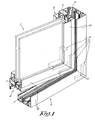
- Figure 1 represents a part of a cabinetwork 1 according to the invention of, in this case, a window 2, which window 2 is provided with a frame 3 and a leaf 4.
- the frame 3 as well as the leaf 4 are built of a number of hollow inner struts 5 and 7 and hollow outer struts 6 and 8 connected at right angles, which are made for example of aluminium or the like.
- each of the above-mentioned insert elements 9 is provided with two legs 10 and 11 standing on each other which are provided in the respective hollow far ends of the connecting struts 5 and 6, 7 and 8 respectively, and which are fixed therein, for example as the legs 10 and 11 are fixed in these struts 5 and 6, 7 and 8 respectively by means of screwing and/or gluing.
- At least one of the above-mentioned insert elements 9 is at least partly made of a fire-retardant, hydrous material 12 such as a hydrous gypseous material or other materials in which water is chemically bonded.
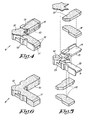
- Figures 2 and 3 represent an insert element 9 in greater detail, which is applied in a cabinetwork 1 according to the invention, which insert element 9 is in this case provided with a number of recesses 13 on one side containing fire-retardant material 12.
- the above-mentioned recesses are in this case made such that the legs 10 and 11 of the insert element 9 have an L-shaped section over at least part of their lengths.
- the above-mentioned fire-retardant material 12 is provided on the walls of the L-shaped strut of said legs 10 and 11, for example by means of gluing, injecting a paste or the like, or by means of mechanical fixing means which are not represented in the figures, such as a snap connection or the like.
- the insert element 9 can be made of any material whatsoever which offers sufficient mechanical strength to obtain a rigid angle joint between the struts 5 and 6, 7 and 8 respectively.
- the cabinetwork 1 offers as a major advantageous that, in case of fire, a reduction in temperature can be obtained at the angle joints of the cabinetwork 1, as a result of which a construction is obtained which resists longer than the conventional cabinetworks.
- the insert element 9 is in this case partly made of another material, such as for example aluminium, one can make sure that the mechanical strength of the insert element 9 is at all times preserved.
- the insert element 9 according to the invention must not necessarily be made of aluminium; on the contrary, it can also be made of many other materials.
- Figures 4 and 5 represent a variant of an insert element 9 which can be used in a cabinetwork 1 according to the invention.
- the insert element 9 from figures 4 and 5 mainly has an analogous construction as the above-described embodiment.
- the insert element 9 is provided with recesses 13 on either side which contain a fire-retardant material 12.
- the above-mentioned recesses 13 are in this case made such that the legs 10 and 11 of the insert element 9 have a T-shaped section over at least part of their lengths, coated on either side with fire-retardant material 12.
- Figure 6 represents another embodiment of an insert element 9 which can be applied in a cabinetwork 1 according to the invention, which insert element 9 is in this case entirely made of a fire-retardant material.
- a cabinetwork 1 which is provided with such an embodiment of an insert element 9 is advantageous in that it offers an even better temperature resistance at the joints between the struts 5 and 6, 7 and 8 respectively, thanks to the large amount of fire-retardant material in these angle joints.
- said insert element 9 can be made entirely or partly hollow, for example as the legs 10 and 11 are hollow, and fire-retardant material can be provided in the hollow space or spaces in said insert element 9.
- Such an embodiment of an insert element 9 has a very large mechanical strength and moreover provides an increased temperature resistance to the cabinetwork 1 in case of fire.
- the above-mentioned insert element is not made as an L-shaped element with two legs standing on each other, but the insert element is made as a T-piece which can be fixed to the ribs of a first strut in a known manner, and in a hollow far end of a second strut standing crosswise on said first strut.
- the insert element can be entirely or partly made of a fire-retardant material.
- the above-mentioned fire-retardant, hydrous material can be made as a mixture of a powder such as gypsum on the one hand, and water on the other hand, whereby this mixture is provided on and/or in the corner piece.
Abstract
Description
- The present invention concerns cabinetwork for windows, doors or the like, which cabinetwork is provided with a number of struts connecting to one another.
- In order to connect the above-mentioned struts to one another, it is known to make these struts hollow and, for example in order to make an angle joint, to join the connecting far ends of these struts by means of an insert element which is provided with two legs standing on each other in the respective hollow far ends of said struts, which legs are fixed therein.
- Fixing the legs of the insert element in the respective hollow far ends of the struts is done, as is known, for example by clamping them in the struts by means of strut lips that are pressed inward and that push against said insert element, or by screwing the insert element in the struts.
- In an analogous manner it is known, in order to make a T-joint with the struts, to make use of an insert element made in the shape of a T-piece which can be fixed for example on ribs of a first strut and which is fixed in a hollow end of a strut standing crosswise on the latter.
- In order to increase the fire safety of cabinetworks, it is known to provide a fire-retardant material in the hollow struts.
- A disadvantage of the known cabinetworks is that, because of the presence of the above-mentioned insert element at the links between the struts, it is not possible to provide any fire-retardant material in these links, such that the temperature at the insert elements will increase too strongly in case of fire, and the fire safety is no longer guaranteed.
- The present invention aims to remedy one or several of the above-mentioned and other disadvantages.
- To this end, the present invention concerns a cabinetwork for windows, doors or the like, which cabinetwork is provided with a number of connecting, hollow struts which are joint by means of an insert element which is fixed with at least one part in a hollow far end of an aforesaid strut, and which is also joint with the connecting strut to be joint with the latter, whereby this insert element is at least partly made of a fire-retardant, hydrous material which makes sure that, in case of fire, the temperature in the struts is restricted thanks to the evaporation of the water.
- An advantage of such cabinetwork according to the invention is that, as the insert element is at least partly made of a fire-retardant, hydrous material, the temperature at the links will be restricted in case of fire, such that the serviceability of the used insert elements is preserved and they can still be fixed in the strut ends in the known manners.
- The above-mentioned insert element is preferably provided with two legs standing on each other, fixed in the respective hollow far ends of the connecting struts. A further preferred characteristic of a cabinetwork according to the invention consists in that the above-mentioned legs of the insert element are provided with at least one recess in one or both sides containing the above-mentioned fire-retardant material.
- This is advantageous in that the mechanical strength of the insert element can be preserved, whereas a fire-retardant effect is nevertheless obtained.
- According to a preferred embodiment of a cabinetwork according to the invention, the respective legs of the insert element have an L- or T-shaped section over at least one part of their length, and a fire-retardant material is provided on one or both sides of the insert element, on the walls of the L- or T-shaped strut.
- By applying this specific construction, the serviceability of the insert element can be entirely preserved, and a good link is obtained between the fire-retardant material and the legs of the insert element thanks to the large contact surface between these legs and the fire-retardant material.
- The present invention also concerns an insert element which can be applied in cabinetwork, as described above, as it is at least partly made of a fire-retardant, hydrous material which makes sure that, in case of fire, the temperature in the struts is restricted thanks to the evaporation of the water.
- In order to better explain the characteristics, of the present invention, the following preferred embodiments of a cabinetwork according to the invention for windows, doors or the like and an insert element applied thereby are described as an example only without being limitative in any way, with reference to the accompanying drawings, in which:
-
figure 1 schematically represents a part of a cabinetwork according to the invention in perspective; -
figure 2 represents the insert element indicated by arrow F2 infigure 1 ; -
figure 3 is an exploded view of an insert element according tofigure 2 ; -
figure 4 represents a variant of an insert element according tofigure 3 ; -
figure 5 is an exploded view of an insert element according tofigure 4 ; -
figure 6 represents another variant of an insert element according tofigure 2 . -
Figure 1 represents a part of a cabinetwork 1 according to the invention of, in this case, awindow 2, whichwindow 2 is provided with aframe 3 and aleaf 4. - In this case, the
frame 3 as well as theleaf 4 are built of a number of hollowinner struts - The above-mentioned inner and
outer struts - At the connecting far ends, the above-mentioned
inner struts figure 1 . - In this example, each of the above-mentioned insert elements 9 is provided with two
legs struts legs struts - According to the invention, at least one of the above-mentioned insert elements 9 is at least partly made of a fire-retardant,
hydrous material 12 such as a hydrous gypseous material or other materials in which water is chemically bonded. -
Figures 2 and 3 represent an insert element 9 in greater detail, which is applied in a cabinetwork 1 according to the invention, which insert element 9 is in this case provided with a number ofrecesses 13 on one side containing fire-retardant material 12. - The above-mentioned recesses are in this case made such that the
legs - The above-mentioned fire-
retardant material 12 is provided on the walls of the L-shaped strut of saidlegs - According to the invention, the insert element 9 can be made of any material whatsoever which offers sufficient mechanical strength to obtain a rigid angle joint between the
struts - As the insert element 9 is partly made of a fire-retardant material, the cabinetwork 1 according to the invention offers as a major advantageous that, in case of fire, a reduction in temperature can be obtained at the angle joints of the cabinetwork 1, as a result of which a construction is obtained which resists longer than the conventional cabinetworks.
- As the insert element 9 is in this case partly made of another material, such as for example aluminium, one can make sure that the mechanical strength of the insert element 9 is at all times preserved. Naturally, the insert element 9 according to the invention must not necessarily be made of aluminium; on the contrary, it can also be made of many other materials.
-
Figures 4 and 5 represent a variant of an insert element 9 which can be used in a cabinetwork 1 according to the invention. - The insert element 9 from
figures 4 and 5 mainly has an analogous construction as the above-described embodiment. - In this example, however, the insert element 9 is provided with
recesses 13 on either side which contain a fire-retardant material 12. - The above-mentioned
recesses 13 are in this case made such that thelegs retardant material 12. - The application of such an insert element 9 provides a cabinetwork having the same advantages as described above with reference to
figures 2 and 3 . -
Figure 6 represents another embodiment of an insert element 9 which can be applied in a cabinetwork 1 according to the invention, which insert element 9 is in this case entirely made of a fire-retardant material. - A cabinetwork 1 which is provided with such an embodiment of an insert element 9 is advantageous in that it offers an even better temperature resistance at the joints between the
struts - According to an embodiment of an insert element 9 which is not represented in the figures, said insert element 9 can be made entirely or partly hollow, for example as the
legs - Such an embodiment of an insert element 9 has a very large mechanical strength and moreover provides an increased temperature resistance to the cabinetwork 1 in case of fire.
- According to a variant of a cabinetwork according to the invention which is not represented in the figures, the above-mentioned insert element is not made as an L-shaped element with two legs standing on each other, but the insert element is made as a T-piece which can be fixed to the ribs of a first strut in a known manner, and in a hollow far end of a second strut standing crosswise on said first strut.
- Naturally, according to the invention, in this case as well, the insert element can be entirely or partly made of a fire-retardant material.
- According to a variant of a cabinetwork according to the invention, the above-mentioned fire-retardant, hydrous material can be made as a mixture of a powder such as gypsum on the one hand, and water on the other hand, whereby this mixture is provided on and/or in the corner piece.
- The present invention is by no means restricted to the embodiments given as an example and represented in the accompanying drawings; on the contrary, such a cabinetwork according to the invention for a door, window or the like and an insert element which can be applied in such a cabinetwork can be made in many shapes and dimensions while still remaining within the scope of the invention.
Claims (11)
- Cabinetwork for windows, doors or the like, which cabinetwork (1) is provided with a number of connecting, hollow struts (5 and 6, 7 and 8 respectively) that are joint by means of an insert element (9) which is fixed with at least one part in a hollow far end of an aforesaid strut (5 or 6), and which is also joint with the connecting strut (7 or 8) to be joint with the latter, characterised in that this insert element (9) is at least partly made of a fire-retardant, hydrous material (12) which makes sure that, in case of fire, the temperature in the struts (5 and 6, 7 and 8 respectively) is restricted thanks to the evaporation of the water.
- Cabinetwork according to claim 1, characterised in that the above-mentioned insert element (9) is provided with two legs (10 and 11) standing on each other which are fixed in the respective hollow far ends of the connecting struts (5 and 6, 7 and 8 respectively).
- Cabinetwork according to claim 2, characterised in that the above-mentioned legs (10 and 11) of the above-mentioned insert element (9) are provided with at least one recess (13) in one or either side containing the above-mentioned fire-retardant, hydrous material (12).
- Cabinetwork according to claim 2 or 3, characterised in that the respective legs (10 and 11) of the insert element have an L-shaped section over at least part of their lengths, and in that the fire-retardant, hydrous material (12) is provided on one side of the insert element (9), on the walls of the L-shaped strut.
- Cabinetwork according to claim 2 or 3, characterised in that the respective legs (10 and 11) of the insert element (9) have a T-shaped section over at least part of their lengths, and in that the fire-retardant, hydrous material (12) is provided on either side of the insert element (9), on the walls of the T-shaped strut.
- Cabinetwork according to any one of the preceding claims, characterised in that the above-mentioned insert element (9) is provided with fixing means to fix fire-retardant, hydrous material (12) to said insert element (9).
- Cabinetwork according to claim 2, characterised in that the above-mentioned legs (10 and 11) of the insert element (9) are made hollow and in that in the cavities in these legs (10 and 11) has been provided the above-mentioned fire-retardant, hydrous material (12).
- Cabinetwork according to claim 1, characterised in that the above-mentioned insert element (9) is entirely made of a fire-retardant, hydrous material (12).
- Cabinetwork according to claim 1, characterised in that the insert element (9) is made in the shape of a T-piece which can be fixed on ribs of a first strut and which can be fixed in a hollow end of a strut standing crosswise on the latter.
- Cabinetwork according to any one of the preceding claims, characterised in that the above-mentioned fire-retardant, hydrous material consists of a gypseous hydrous material.
- Insert element, characterised in that it can be applied in a cabinetwork (1) according to any one of the preceding claims characterised in that it is at least partly made of fire-retardant, hydrous material (12).
Priority Applications (1)
| Application Number | Priority Date | Filing Date | Title |
|---|---|---|---|
| PL08003647T PL1970522T3 (en) | 2007-03-14 | 2008-02-28 | Joinery work for windows and doors or the like |
Applications Claiming Priority (1)
| Application Number | Priority Date | Filing Date | Title |
|---|---|---|---|
| BE2007/0108A BE1017490A3 (en) | 2007-03-14 | 2007-03-14 | JOB WORK FOR WINDOWS, DOORS OR THE LIKE AND IMPLEMENTING ELEMENT THAT IS APPLIED IN SUCH JOB WORK. |
Publications (3)
| Publication Number | Publication Date |
|---|---|
| EP1970522A2 true EP1970522A2 (en) | 2008-09-17 |
| EP1970522A3 EP1970522A3 (en) | 2008-12-24 |
| EP1970522B1 EP1970522B1 (en) | 2010-07-14 |
Family
ID=38442134
Family Applications (1)
| Application Number | Title | Priority Date | Filing Date |
|---|---|---|---|
| EP08003647A Active EP1970522B1 (en) | 2007-03-14 | 2008-02-28 | Joinery work for windows and doors or the like |
Country Status (5)
| Country | Link |
|---|---|
| EP (1) | EP1970522B1 (en) |
| AT (1) | ATE474121T1 (en) |
| BE (1) | BE1017490A3 (en) |
| DE (1) | DE602008001741D1 (en) |
| PL (1) | PL1970522T3 (en) |
Citations (1)
| Publication number | Priority date | Publication date | Assignee | Title |
|---|---|---|---|---|
| EP1296013A1 (en) | 2001-07-07 | 2003-03-26 | Bemofensterbau Gmbh | Fire-resistant building profile and method for producing the same |
Family Cites Families (3)
| Publication number | Priority date | Publication date | Assignee | Title |
|---|---|---|---|---|
| DE2300281A1 (en) * | 1973-01-04 | 1974-07-11 | Guenter Dr Ing Koepke | Corner reinforcement - for plastic profile door or window frames etc. |
| DE20311294U1 (en) * | 2003-07-23 | 2003-10-02 | Wicona Bausysteme Gmbh | Connector for hollow aluminum profiles used to build window or door frames has two or more arms which fit into profiles, connector comprising hollow metal profile filled with molded plastic or foamed plastic core |
| DE20316758U1 (en) * | 2003-10-31 | 2003-12-24 | SCHÜCO International KG | Corner connector used in the production of window frames, door frames or facade connectors comprises a molded body having two arms, and covers clamped on opposite-lying sides of the arms by pins engaging in channels provided on the arms |
-
2007
- 2007-03-14 BE BE2007/0108A patent/BE1017490A3/en not_active IP Right Cessation
-
2008
- 2008-02-28 PL PL08003647T patent/PL1970522T3/en unknown
- 2008-02-28 DE DE602008001741T patent/DE602008001741D1/en active Active
- 2008-02-28 AT AT08003647T patent/ATE474121T1/en active
- 2008-02-28 EP EP08003647A patent/EP1970522B1/en active Active
Patent Citations (1)
| Publication number | Priority date | Publication date | Assignee | Title |
|---|---|---|---|---|
| EP1296013A1 (en) | 2001-07-07 | 2003-03-26 | Bemofensterbau Gmbh | Fire-resistant building profile and method for producing the same |
Also Published As
| Publication number | Publication date |
|---|---|
| BE1017490A3 (en) | 2008-10-07 |
| EP1970522B1 (en) | 2010-07-14 |
| DE602008001741D1 (en) | 2010-08-26 |
| EP1970522A3 (en) | 2008-12-24 |
| ATE474121T1 (en) | 2010-07-15 |
| PL1970522T3 (en) | 2010-12-31 |
Similar Documents
| Publication | Publication Date | Title |
|---|---|---|
| EP2878752B1 (en) | Prefabricated structure of composite window/door apparatus using different frame materials | |
| EP0865559B1 (en) | Window or door made from a core consisting of foam-containing sections | |
| US4360553A (en) | Sandwich panel | |
| US8511011B2 (en) | Structural frame member having a capped corner key passage | |
| SE469800B (en) | Door leaf Profile | |
| EP3240938A2 (en) | Window frame system | |
| EP2302277A2 (en) | Insulation half shell body | |
| US20160208497A1 (en) | Combination frame material | |
| AT13056U1 (en) | THERMALLY ISOLATED PROFILE | |
| EP1970522A2 (en) | Cabinetwork for windows and doors or the like, and insert element applied in such cabinetwork | |
| KR100939115B1 (en) | Sash bar suitable for insulating window units | |
| KR101826762B1 (en) | Plates combination type skin board | |
| KR102273300B1 (en) | Insulation structure of curtain wall with improved heat insulation property | |
| EP2042678A1 (en) | Door or window assembly with glass inserts | |
| KR101657419B1 (en) | Multi purpose adiabatic frame and with a frame windows | |
| DE102004031824B4 (en) | security Zone | |
| SK29594A3 (en) | Composite framing profile | |
| EP1691022A2 (en) | Corner piece and joinery which is provided with such a corner piece | |
| KR200407407Y1 (en) | Board of structural interior decoration | |
| DE202007015319U1 (en) | Insulator for window, door and façade systems | |
| DE2405902A1 (en) | Rectangular prefabricated insulating plate for refrigerators - has tongue and groove edge connectors moulded into plate | |
| WO2003048493A1 (en) | Composite profile for door and window frames | |
| EP4036361A1 (en) | A window frame assembly | |
| DE19650101A1 (en) | Tongue=and=groove join for wooden sauna etc. Cubicle walling | |
| ITTO20070533A1 (en) | PROFILE ASSEMBLY MULTIFUNCTION SYSTEM. |
Legal Events
| Date | Code | Title | Description |
|---|---|---|---|
| PUAI | Public reference made under article 153(3) epc to a published international application that has entered the european phase |
Free format text: ORIGINAL CODE: 0009012 |
|
| AK | Designated contracting states |
Kind code of ref document: A2 Designated state(s): AT BE BG CH CY CZ DE DK EE ES FI FR GB GR HR HU IE IS IT LI LT LU LV MC MT NL NO PL PT RO SE SI SK TR |
|
| AX | Request for extension of the european patent |
Extension state: AL BA MK RS |
|
| PUAL | Search report despatched |
Free format text: ORIGINAL CODE: 0009013 |
|
| AK | Designated contracting states |
Kind code of ref document: A3 Designated state(s): AT BE BG CH CY CZ DE DK EE ES FI FR GB GR HR HU IE IS IT LI LT LU LV MC MT NL NO PL PT RO SE SI SK TR |
|
| AX | Request for extension of the european patent |
Extension state: AL BA MK RS |
|
| 17P | Request for examination filed |
Effective date: 20090217 |
|
| AKX | Designation fees paid |
Designated state(s): AT BE BG CH CY CZ DE DK EE ES FI FR GB GR HR HU IE IS IT LI LT LU LV MC MT NL NO PL PT RO SE SI SK TR |
|
| GRAC | Information related to communication of intention to grant a patent modified |
Free format text: ORIGINAL CODE: EPIDOSCIGR1 |
|
| GRAP | Despatch of communication of intention to grant a patent |
Free format text: ORIGINAL CODE: EPIDOSNIGR1 |
|
| RTI1 | Title (correction) |
Free format text: JOINERY WORK FOR WINDOWS AND DOORS OR THE LIKE |
|
| GRAS | Grant fee paid |
Free format text: ORIGINAL CODE: EPIDOSNIGR3 |
|
| GRAA | (expected) grant |
Free format text: ORIGINAL CODE: 0009210 |
|
| AK | Designated contracting states |
Kind code of ref document: B1 Designated state(s): AT BE BG CH CY CZ DE DK EE ES FI FR GB GR HR HU IE IS IT LI LT LU LV MC MT NL NO PL PT RO SE SI SK TR |
|
| REG | Reference to a national code |
Ref country code: GB Ref legal event code: FG4D |
|
| REG | Reference to a national code |
Ref country code: CH Ref legal event code: EP |
|
| REG | Reference to a national code |
Ref country code: IE Ref legal event code: FG4D |
|
| REF | Corresponds to: |
Ref document number: 602008001741 Country of ref document: DE Date of ref document: 20100826 Kind code of ref document: P |
|
| REG | Reference to a national code |
Ref country code: CH Ref legal event code: NV Representative=s name: FIAMMENGHI-FIAMMENGHI |
|
| REG | Reference to a national code |
Ref country code: NL Ref legal event code: T3 |
|
| REG | Reference to a national code |
Ref country code: PL Ref legal event code: T3 |
|
| PG25 | Lapsed in a contracting state [announced via postgrant information from national office to epo] |
Ref country code: NO Free format text: LAPSE BECAUSE OF FAILURE TO SUBMIT A TRANSLATION OF THE DESCRIPTION OR TO PAY THE FEE WITHIN THE PRESCRIBED TIME-LIMIT Effective date: 20101014 Ref country code: FI Free format text: LAPSE BECAUSE OF FAILURE TO SUBMIT A TRANSLATION OF THE DESCRIPTION OR TO PAY THE FEE WITHIN THE PRESCRIBED TIME-LIMIT Effective date: 20100714 |
|
| PG25 | Lapsed in a contracting state [announced via postgrant information from national office to epo] |
Ref country code: IS Free format text: LAPSE BECAUSE OF FAILURE TO SUBMIT A TRANSLATION OF THE DESCRIPTION OR TO PAY THE FEE WITHIN THE PRESCRIBED TIME-LIMIT Effective date: 20101114 Ref country code: HR Free format text: LAPSE BECAUSE OF FAILURE TO SUBMIT A TRANSLATION OF THE DESCRIPTION OR TO PAY THE FEE WITHIN THE PRESCRIBED TIME-LIMIT Effective date: 20100714 Ref country code: SI Free format text: LAPSE BECAUSE OF FAILURE TO SUBMIT A TRANSLATION OF THE DESCRIPTION OR TO PAY THE FEE WITHIN THE PRESCRIBED TIME-LIMIT Effective date: 20100714 Ref country code: CY Free format text: LAPSE BECAUSE OF FAILURE TO SUBMIT A TRANSLATION OF THE DESCRIPTION OR TO PAY THE FEE WITHIN THE PRESCRIBED TIME-LIMIT Effective date: 20100714 Ref country code: BG Free format text: LAPSE BECAUSE OF FAILURE TO SUBMIT A TRANSLATION OF THE DESCRIPTION OR TO PAY THE FEE WITHIN THE PRESCRIBED TIME-LIMIT Effective date: 20101014 |
|
| PG25 | Lapsed in a contracting state [announced via postgrant information from national office to epo] |
Ref country code: GR Free format text: LAPSE BECAUSE OF FAILURE TO SUBMIT A TRANSLATION OF THE DESCRIPTION OR TO PAY THE FEE WITHIN THE PRESCRIBED TIME-LIMIT Effective date: 20101015 Ref country code: SE Free format text: LAPSE BECAUSE OF FAILURE TO SUBMIT A TRANSLATION OF THE DESCRIPTION OR TO PAY THE FEE WITHIN THE PRESCRIBED TIME-LIMIT Effective date: 20100714 Ref country code: LV Free format text: LAPSE BECAUSE OF FAILURE TO SUBMIT A TRANSLATION OF THE DESCRIPTION OR TO PAY THE FEE WITHIN THE PRESCRIBED TIME-LIMIT Effective date: 20100714 |
|
| PG25 | Lapsed in a contracting state [announced via postgrant information from national office to epo] |
Ref country code: DK Free format text: LAPSE BECAUSE OF FAILURE TO SUBMIT A TRANSLATION OF THE DESCRIPTION OR TO PAY THE FEE WITHIN THE PRESCRIBED TIME-LIMIT Effective date: 20100714 |
|
| PLBE | No opposition filed within time limit |
Free format text: ORIGINAL CODE: 0009261 |
|
| STAA | Information on the status of an ep patent application or granted ep patent |
Free format text: STATUS: NO OPPOSITION FILED WITHIN TIME LIMIT |
|
| PG25 | Lapsed in a contracting state [announced via postgrant information from national office to epo] |
Ref country code: RO Free format text: LAPSE BECAUSE OF FAILURE TO SUBMIT A TRANSLATION OF THE DESCRIPTION OR TO PAY THE FEE WITHIN THE PRESCRIBED TIME-LIMIT Effective date: 20100714 Ref country code: SK Free format text: LAPSE BECAUSE OF FAILURE TO SUBMIT A TRANSLATION OF THE DESCRIPTION OR TO PAY THE FEE WITHIN THE PRESCRIBED TIME-LIMIT Effective date: 20100714 Ref country code: EE Free format text: LAPSE BECAUSE OF FAILURE TO SUBMIT A TRANSLATION OF THE DESCRIPTION OR TO PAY THE FEE WITHIN THE PRESCRIBED TIME-LIMIT Effective date: 20100714 Ref country code: IT Free format text: LAPSE BECAUSE OF FAILURE TO SUBMIT A TRANSLATION OF THE DESCRIPTION OR TO PAY THE FEE WITHIN THE PRESCRIBED TIME-LIMIT Effective date: 20100714 |
|
| 26N | No opposition filed |
Effective date: 20110415 |
|
| PG25 | Lapsed in a contracting state [announced via postgrant information from national office to epo] |
Ref country code: ES Free format text: LAPSE BECAUSE OF FAILURE TO SUBMIT A TRANSLATION OF THE DESCRIPTION OR TO PAY THE FEE WITHIN THE PRESCRIBED TIME-LIMIT Effective date: 20101025 |
|
| REG | Reference to a national code |
Ref country code: DE Ref legal event code: R097 Ref document number: 602008001741 Country of ref document: DE Effective date: 20110415 |
|
| PG25 | Lapsed in a contracting state [announced via postgrant information from national office to epo] |
Ref country code: MC Free format text: LAPSE BECAUSE OF NON-PAYMENT OF DUE FEES Effective date: 20110228 |
|
| REG | Reference to a national code |
Ref country code: IE Ref legal event code: MM4A |
|
| PG25 | Lapsed in a contracting state [announced via postgrant information from national office to epo] |
Ref country code: MT Free format text: LAPSE BECAUSE OF FAILURE TO SUBMIT A TRANSLATION OF THE DESCRIPTION OR TO PAY THE FEE WITHIN THE PRESCRIBED TIME-LIMIT Effective date: 20100714 |
|
| PG25 | Lapsed in a contracting state [announced via postgrant information from national office to epo] |
Ref country code: IE Free format text: LAPSE BECAUSE OF NON-PAYMENT OF DUE FEES Effective date: 20110228 |
|
| GBPC | Gb: european patent ceased through non-payment of renewal fee |
Effective date: 20120228 |
|
| PG25 | Lapsed in a contracting state [announced via postgrant information from national office to epo] |
Ref country code: GB Free format text: LAPSE BECAUSE OF NON-PAYMENT OF DUE FEES Effective date: 20120228 |
|
| PG25 | Lapsed in a contracting state [announced via postgrant information from national office to epo] |
Ref country code: LU Free format text: LAPSE BECAUSE OF NON-PAYMENT OF DUE FEES Effective date: 20110228 |
|
| PG25 | Lapsed in a contracting state [announced via postgrant information from national office to epo] |
Ref country code: PT Free format text: LAPSE BECAUSE OF NON-PAYMENT OF DUE FEES Effective date: 20100714 |
|
| PG25 | Lapsed in a contracting state [announced via postgrant information from national office to epo] |
Ref country code: TR Free format text: LAPSE BECAUSE OF FAILURE TO SUBMIT A TRANSLATION OF THE DESCRIPTION OR TO PAY THE FEE WITHIN THE PRESCRIBED TIME-LIMIT Effective date: 20100714 |
|
| PG25 | Lapsed in a contracting state [announced via postgrant information from national office to epo] |
Ref country code: HU Free format text: LAPSE BECAUSE OF FAILURE TO SUBMIT A TRANSLATION OF THE DESCRIPTION OR TO PAY THE FEE WITHIN THE PRESCRIBED TIME-LIMIT Effective date: 20100714 |
|
| REG | Reference to a national code |
Ref country code: FR Ref legal event code: PLFP Year of fee payment: 9 |
|
| REG | Reference to a national code |
Ref country code: FR Ref legal event code: PLFP Year of fee payment: 10 |
|
| REG | Reference to a national code |
Ref country code: FR Ref legal event code: PLFP Year of fee payment: 11 |
|
| PGFP | Annual fee paid to national office [announced via postgrant information from national office to epo] |
Ref country code: LT Payment date: 20230201 Year of fee payment: 16 Ref country code: FR Payment date: 20230127 Year of fee payment: 16 Ref country code: CZ Payment date: 20230126 Year of fee payment: 16 Ref country code: CH Payment date: 20230307 Year of fee payment: 16 Ref country code: AT Payment date: 20230216 Year of fee payment: 16 |
|
| PGFP | Annual fee paid to national office [announced via postgrant information from national office to epo] |
Ref country code: PL Payment date: 20230210 Year of fee payment: 16 Ref country code: DE Payment date: 20230217 Year of fee payment: 16 Ref country code: BE Payment date: 20230124 Year of fee payment: 16 |
|
| P01 | Opt-out of the competence of the unified patent court (upc) registered |
Effective date: 20230418 |
|
| PGFP | Annual fee paid to national office [announced via postgrant information from national office to epo] |
Ref country code: NL Payment date: 20230124 Year of fee payment: 16 |
|
| PGFP | Annual fee paid to national office [announced via postgrant information from national office to epo] |
Ref country code: NL Payment date: 20240118 Year of fee payment: 17 |
|
| PGFP | Annual fee paid to national office [announced via postgrant information from national office to epo] |
Ref country code: LT Payment date: 20240126 Year of fee payment: 17 |