US8511011B2 - Structural frame member having a capped corner key passage - Google Patents

Structural frame member having a capped corner key passage Download PDF

Info

Publication number
US8511011B2
US8511011B2 US13/604,037 US201213604037A US8511011B2 US 8511011 B2 US8511011 B2 US 8511011B2 US 201213604037 A US201213604037 A US 201213604037A US 8511011 B2 US8511011 B2 US 8511011B2
Authority
US
United States
Prior art keywords
structural frame
key
body portion
key passage
pair
Prior art date
Legal status (The legal status is an assumption and is not a legal conclusion. Google has not performed a legal analysis and makes no representation as to the accuracy of the status listed.)
Active
Application number
US13/604,037
Other versions
US20130111846A1 (en
Inventor
Brian A. Emanuel
Current Assignee (The listed assignees may be inaccurate. Google has not performed a legal analysis and makes no representation or warranty as to the accuracy of the list.)
James Hardie Technology Ltd
Original Assignee
James Hardie Technology Ltd
Priority date (The priority date is an assumption and is not a legal conclusion. Google has not performed a legal analysis and makes no representation as to the accuracy of the date listed.)
Filing date
Publication date
Family has litigation
First worldwide family litigation filed litigation Critical https://patents.darts-ip.com/?family=48222525&utm_source=google_patent&utm_medium=platform_link&utm_campaign=public_patent_search&patent=US8511011(B2) "Global patent litigation dataset” by Darts-ip is licensed under a Creative Commons Attribution 4.0 International License.
US case filed in Wisconsin Western District Court litigation https://portal.unifiedpatents.com/litigation/Wisconsin%20Western%20District%20Court/case/3%3A14-cv-00535 Source: District Court Jurisdiction: Wisconsin Western District Court "Unified Patents Litigation Data" by Unified Patents is licensed under a Creative Commons Attribution 4.0 International License.
Application filed by James Hardie Technology Ltd filed Critical James Hardie Technology Ltd
Priority to US13/604,037 priority Critical patent/US8511011B2/en
Assigned to James Hardie Technology Limited reassignment James Hardie Technology Limited ASSIGNMENT OF ASSIGNORS INTEREST (SEE DOCUMENT FOR DETAILS). Assignors: EMANUEL, BRIAN A.
Publication of US20130111846A1 publication Critical patent/US20130111846A1/en
Application granted granted Critical
Publication of US8511011B2 publication Critical patent/US8511011B2/en
Assigned to James Hardie Technology Limited reassignment James Hardie Technology Limited ASSIGNMENT OF ASSIGNORS INTEREST (SEE DOCUMENT FOR DETAILS). Assignors: BERANEK, GERALD D.
Active legal-status Critical Current
Anticipated expiration legal-status Critical

Links

Images

Classifications

    • EFIXED CONSTRUCTIONS
    • E06DOORS, WINDOWS, SHUTTERS, OR ROLLER BLINDS IN GENERAL; LADDERS
    • E06BFIXED OR MOVABLE CLOSURES FOR OPENINGS IN BUILDINGS, VEHICLES, FENCES OR LIKE ENCLOSURES IN GENERAL, e.g. DOORS, WINDOWS, BLINDS, GATES
    • E06B3/00Window sashes, door leaves, or like elements for closing wall or like openings; Layout of fixed or moving closures, e.g. windows in wall or like openings; Features of rigidly-mounted outer frames relating to the mounting of wing frames
    • E06B3/04Wing frames not characterised by the manner of movement
    • E06B3/06Single frames
    • E06B3/08Constructions depending on the use of specified materials
    • E06B3/20Constructions depending on the use of specified materials of plastics
    • E06B3/22Hollow frames
    • EFIXED CONSTRUCTIONS
    • E06DOORS, WINDOWS, SHUTTERS, OR ROLLER BLINDS IN GENERAL; LADDERS
    • E06BFIXED OR MOVABLE CLOSURES FOR OPENINGS IN BUILDINGS, VEHICLES, FENCES OR LIKE ENCLOSURES IN GENERAL, e.g. DOORS, WINDOWS, BLINDS, GATES
    • E06B3/00Window sashes, door leaves, or like elements for closing wall or like openings; Layout of fixed or moving closures, e.g. windows in wall or like openings; Features of rigidly-mounted outer frames relating to the mounting of wing frames
    • E06B3/96Corner joints or edge joints for windows, doors, or the like frames or wings
    • E06B3/964Corner joints or edge joints for windows, doors, or the like frames or wings using separate connection pieces, e.g. T-connection pieces
    • E06B3/9645Mitre joints
    • EFIXED CONSTRUCTIONS
    • E06DOORS, WINDOWS, SHUTTERS, OR ROLLER BLINDS IN GENERAL; LADDERS
    • E06BFIXED OR MOVABLE CLOSURES FOR OPENINGS IN BUILDINGS, VEHICLES, FENCES OR LIKE ENCLOSURES IN GENERAL, e.g. DOORS, WINDOWS, BLINDS, GATES
    • E06B3/00Window sashes, door leaves, or like elements for closing wall or like openings; Layout of fixed or moving closures, e.g. windows in wall or like openings; Features of rigidly-mounted outer frames relating to the mounting of wing frames
    • E06B3/96Corner joints or edge joints for windows, doors, or the like frames or wings
    • E06B3/964Corner joints or edge joints for windows, doors, or the like frames or wings using separate connection pieces, e.g. T-connection pieces
    • E06B3/968Corner joints or edge joints for windows, doors, or the like frames or wings using separate connection pieces, e.g. T-connection pieces characterised by the way the connecting pieces are fixed in or on the frame members
    • E06B3/9681Corner joints or edge joints for windows, doors, or the like frames or wings using separate connection pieces, e.g. T-connection pieces characterised by the way the connecting pieces are fixed in or on the frame members by press fit or adhesion
    • E06B3/9682Mitre joints
    • YGENERAL TAGGING OF NEW TECHNOLOGICAL DEVELOPMENTS; GENERAL TAGGING OF CROSS-SECTIONAL TECHNOLOGIES SPANNING OVER SEVERAL SECTIONS OF THE IPC; TECHNICAL SUBJECTS COVERED BY FORMER USPC CROSS-REFERENCE ART COLLECTIONS [XRACs] AND DIGESTS
    • Y10TECHNICAL SUBJECTS COVERED BY FORMER USPC
    • Y10TTECHNICAL SUBJECTS COVERED BY FORMER US CLASSIFICATION
    • Y10T29/00Metal working
    • Y10T29/49Method of mechanical manufacture
    • Y10T29/49616Structural member making
    • Y10T29/49623Static structure, e.g., a building component
    • YGENERAL TAGGING OF NEW TECHNOLOGICAL DEVELOPMENTS; GENERAL TAGGING OF CROSS-SECTIONAL TECHNOLOGIES SPANNING OVER SEVERAL SECTIONS OF THE IPC; TECHNICAL SUBJECTS COVERED BY FORMER USPC CROSS-REFERENCE ART COLLECTIONS [XRACs] AND DIGESTS
    • Y10TECHNICAL SUBJECTS COVERED BY FORMER USPC
    • Y10TTECHNICAL SUBJECTS COVERED BY FORMER US CLASSIFICATION
    • Y10T29/00Metal working
    • Y10T29/49Method of mechanical manufacture
    • Y10T29/49826Assembling or joining
    • Y10T29/49947Assembling or joining by applying separate fastener
    • Y10T29/49966Assembling or joining by applying separate fastener with supplemental joining

Definitions

  • This invention relates generally to a structural frame member, and more particularly to a structural frame member that can be joined together with other frame members to form a frame assembly.
  • Frame members such as window frame members, are commonly formed with a key passage that is adapted to receive a corner key used to secure adjacent frame members together.
  • the key passage is in the form of an enclosed passage located within an inner area of the frame member.
  • the key passage is defined by a series of walls, which are typically integrally formed with each other and with the remaining structure of the frame member, such as in an extrusion or pultrusion process.
  • the present invention seeks to improve upon such prior art by providing a key passage defined by a series of walls that are not integrally formed with each other.
  • a structural frame member includes a body portion having a first section defining a number of axially extending passages and a second section defining a key passage area.
  • a cap portion is configured for engagement with the key passage area.
  • the cap portion and the key passage area of the body portion cooperate to define an enclosed key passage.
  • the key passage area of the body portion may be defined by a pair of spaced apart protrusions that extend from a wall forming a part of the body portion, and the cap portion is configured for engagement with the pair of spaced apart protrusions.
  • the cap portion and the pair of spaced apart protrusions include snap-type engagement structure that secures the cap portion to the pair of spaced apart protrusions upon application of a transversely directed force to the cap portion.
  • the first section of the body portion may be an outer section and the second section of the body portion may be an inner section, with the outer and inner sections being separated at least in part by the wall from which the spaced apart protrusions extend.
  • the body portion defines a depth, and the enclosed key passage defined by the key passage area of the body portion and the cap portion extends across a majority of the depth of the body portion.
  • FIG. 1 depicts a front, partial exploded view of one embodiment of a frame assembly system.
  • FIG. 5 depicts a perspective view of the lineal member of FIGS. 3-4 .
  • FIG. 6 depicts a cross-sectional view of the cap of FIG. 3 .
  • FIG. 9 is a side view of an assembled corner key of FIG. 8 .
  • FIG. 10 depicts a cross-sectional view of a different lineal member for a use in a frame of a casement window.
  • FIG. 11 depicts a cross-sectional view of another lineal member for a use in a frame of a picture window.
  • FIG. 12 depicts a cross-sectional view of another lineal member for use in a frame of a double hung window.
  • the systems and methods described herein related generally to joining frame members together to form frame assemblies using corner keys which fit inside of the ends of the frame members. More particularly, the systems and methods relate to use of frame members having uniform cross-sections such as those formed by pultrusion or extrusion.
  • the frame assembly described herein provides a high level of thermal insulation by virtue of having two or three or sometimes four enclosed longitudinal cavities defined within each frame member.
  • the frame assembly includes one or more corner keys which are positioned adjacent to an outer perimeter of the assembled frame.
  • the frame member configuration permits insertion of the corner keys without any milling, that is, without removing any material from the interior of the frame member.
  • a corner key cavity extends across at least 60% of a depth of a frame member.
  • the frame assembly system includes a cavity for a corner key that is defined between a lineal member and a cap. In some embodiments, this corner key cavity is located adjacent to an outer perimeter of the assembled frame. This position of the corner key improves the strength and design pressure of the assembled frame.
  • FIG. 1 an exploded view of a frame assembly is illustrated including four frame members 10 and four corner keys 14 .
  • FIG. 2 shows an assembled frame 16 including the four frame members 10 .
  • the corner keys are not visible in FIG. 2 because each corner key 14 fits within the interior cavities of two adjacent frame members 10 to form a corner joint.
  • the frame 16 defines an inner perimeter 18 and an outer perimeter 20 .
  • the opening 22 defined by the frame's inner perimeter 18 may be configured to mate with a window sash.
  • the sash or the opening 22 may hold a pane of glass, an insulating glass unit, other transparent or translucent material, or a sheet.
  • the concepts related to frame members and assembly methods described herein are sometimes described in the context of windows. However, the same concepts apply to joining other structural or architectural elements at a corner joint. Many of the embodiments described herein have four frame members forming a frame assembly. However, it is also possible to apply the concepts described herein to an assembly that has two frame members, three frame members, five frame members, six frame members, and other numbers of frame members. Where a frame assembly does not from a closed perimeter, such as where there are two frame linear members at right angles to each other, the inner perimeter can be defined on the side of the frame assembly that has an angle between the frame members of less than 180 degrees. The outer perimeter can be defined on the side of the frame assembly that has an angle between frame members of greater than 180 degrees.
  • the frames of FIGS. 1-2 are rectangular frames. However, it is also possible to apply the frame assembly concepts described herein to non-rectangular frames, such as trapezoidal window frames, half-circle window frames, and other window frames, as will be discussed further herein.
  • corner keys 14 are configured with legs that extend into and fit within the hollow profiles of the frame members 10 to join the ends of the frame members 10 together. Adhesives can then be injected into the corners through specially designed passages to bond the corner keys 14 within the frame members 10 and thereby to secure the ends of the frame members 10 permanently together.
  • the adhesive is a two-part adhesive. The adhesive is selected to be compatible with the material of the frame member 10 and the material of the corner key 14 .
  • a two-part adhesive is NovaGard 900-200 Corner Key Bonding Adhesive, available from NovaGard Solutions, Cleveland, Ohio, which is compatible with the resins in a fiberglass frame member 10 and compatible with a corner key 14 made of acrylonitrile-butadiene-styrene (ABS).
  • ABS acrylonitrile-butadiene-styrene
  • the adhesive when cured forms a polymer.
  • a hot melt adhesive is injected at the corners.
  • a thermoplastic adhesive is injected at the corners.
  • FIG. 3 a cross-sectional view of a frame member 10 is illustrated.
  • the frame member 10 includes two components: a lineal member 40 and a cap 42 .
  • the lineal member 40 is also illustrated in FIGS. 4 and 5 .
  • the cap 42 is also illustrated in FIGS. 6 and 7 .
  • the cap 42 attaches to the lineal member 40 by a snap-fit attachment.
  • a cavity 44 is formed by the attachment of the cap 42 to the lineal member 40 .
  • the cavity 44 is configured to receive one leg of the corner key 14 and is referred to as the corner key cavity 44 .
  • An inner first side 43 of the frame member 10 will define the inner perimeter 18 in the assembled frame 16
  • the opposite outer second side 45 of the frame member 10 will define the outer perimeter 20 in the assembled frame 16 (See FIG. 2 ).
  • the corner key cavity 44 is adjacent to the outer first side 45 of the frame member 10 that will define the outer perimeter 20 of the frame. This position increases the strength of the assembled frame compared to other positions of the corner key 14 .
  • the corner key cavity 44 is a longitudinal cavity that extends along the entire length of the frame member 10 .
  • the corner key cavity 44 is bounded by a closed perimeter. The presence of this bounded cavity improves the insulation value of the frame member 10 .
  • the corner key cavity 44 extends across most of the depth dimension of the frame member, thereby further increasing the strength of the assembled frame 16 .
  • the depth dimension D of the frame member 10 is measured from an outside surface 146 of an outer first side 46 to an outside surface 148 of an opposite inner second side 48 of the frame member 10 .
  • the depth extension E of the corner key 14 is measured across each of the legs 86 , 88 of the corner key 14 as shown in FIG. 8 .
  • the corner key 14 fits snugly into the corner key cavity 44 .
  • another way to measure the depth extension E of the corner key 14 is by measuring the inside dimension of the corner key cavity 44 .
  • the depth extension E of the corner key 14 can also be measured from an inside surface 160 of a first protrusion 60 to an inside surface 161 of a second protrusion 61 .
  • the corner key cavity extends across at least about 60% of the depth of the frame member. In some embodiments, the corner key cavity extends across at least about 65% of the depth of the frame member. In some embodiments, the corner key cavity extends across at least about 67% of the depth of the frame member. In some embodiments, the corner key cavity extends across at least about 70% of the depth of the frame member. In some embodiments, the corner key cavity extends across at least about 72% of the depth of the frame member. In some embodiments, the corner key cavity extends across at least about 75% of the depth of the frame member. In the embodiment of FIGS. 3-5 , the corner key extends across about 70% of the depth of the frame member. In the embodiment of FIG.
  • the corner key extends across about 67% of the depth of the frame member. In the embodiment of FIG. 11 , the corner key extends across about 75% of the depth of the frame member. In the embodiment of FIG. 12 , the corner key extends across about 71% of the depth of the frame member.
  • the assembled frame includes a first face and a second face.
  • One of the faces is facing the viewer in FIG. 2 .
  • the first face might be the exterior face of a building's window, while the second face is the interior face of a building's window.
  • the first side 46 of the frame member 10 will define part of the first face while the opposite second side 48 of the frame member 10 will define the second face.
  • the lineal member 40 defines a first interior cavity 50 and a second interior cavity 52 .
  • the inclusion of multiple interior cavities 50 , 52 increases the insulating properties of the frame 16 .
  • the interior cavities 50 , 52 are longitudinal cavities that extend along the length of the frame member 10 .
  • the lineal member 40 further defines a third interior cavity 53 .
  • the third interior cavity 53 is adjacent to one side 48 , while the first interior cavity is adjacent to the other side 46 .
  • the second interior cavity 52 is positioned between the first and third interior cavities 50 , 53 .
  • the lineal member defines at least one interior cavity and an open area for a corner key cavity. In one embodiment, the lineal member defines at least two interior cavities and an open area for a corner key cavity. In one embodiment, the lineal member defines at least three interior cavities and an open area for a corner key cavity. In one embodiment, the lineal member defines at least four interior cavities and an open area for a corner key cavity.
  • the lineal member 40 and the cap 42 each include attachment structures that interact with each other to cause a snap-fit attachment of the cap 42 to the lineal member 40 .
  • the lineal member 40 shown in FIGS. 4 and 5 includes an exterior surface 54 and first attachment structures 56 , 57 defined by the exterior surface 54 .
  • the first attachment structure includes two protrusions 56 , 57 including nubs 58 near the ends of the protrusions 56 , 57 .
  • Mating attachment structures 60 , 61 on the cap 42 are seen in FIGS. 6 and 7 , and can also be referred to as protrusions 60 , 61 defining nubs 62 at their ends.
  • the first and second attachment structures 56 , 57 , 60 , 61 are configured to lock together when brought into contact.
  • the second attachment structures 60 , 61 of the cap fit within the first attachment structures 56 , 57 extending from the lineal member 40 .
  • the first and second attachment structures are longitudinal features that extend along the length of the lineal member 40 and cap 42 , respectively.
  • the attachment structures are two longitudinal protrusions with nub structures which lock into an attached position with two similar longitudinal protrusions.
  • the attachment structure of the lineal member and the attachment structure of the cap are connected by a snap-fit.
  • a snap-fit refers to a connection between parts where mating parts exert a cam action, flexing until one part slips past a raised lip on another part.
  • Other types of attachment structures are present in some embodiments.
  • FIG. 8 is an exploded perspective view of the two parts that make up the corner key 14 in one embodiment.
  • the outer portion 82 attaches to the inner portion 84 using interlocking mechanical structures to form the corner key 14 .
  • ease of manufacturing is increased.
  • the two-part corner key 14 allows adhesive to flow between the inner portion 84 and outer portion 82 .
  • the corner key 14 of FIGS. 8 and 9 has been found to be structurally solid after the adhesive is injected and has cured.
  • FIG. 9 is a side view of one embodiment of the corner key 14 , which includes a first leg 86 and a second leg 88 forming a 90 degree angle with the first leg 86 .
  • the angle is not 90 degrees.
  • the angle between the legs is adjustable.
  • the corner key joint 90 is the portion of the corner key 14 where the two legs 86 , 88 or two halves are connected.
  • the joint 90 of the corner key 14 is flexible and acts as a hinge. As a result, the angle between the first and second legs 86 , 88 can vary as needed depending on the frame shape.
  • the corner key 14 includes channels and recesses for routing and retaining adhesive that is injected into the corner area after the corner key 14 is positioned within adjacent frame members 10 .
  • the adhesive improves the structural integrity of the joint.
  • the corner key 14 can be made from a wide variety of materials including nylon and crylonitrile-butadiene-styrene (ABS). In one embodiment, the corner key 14 is made from a non-metallic material.
  • the corner key 14 is configured to fit tightly within the corner key cavity 44 .
  • a measured amount of adhesive is injected into the joint once the corner key 14 is in place.
  • the corner key cavity 44 and the corner key 14 are designed to encourage the adhesive to flow along each leg 86 , 88 , up against the ramp structures at the ends of the legs, through openings in the corner key and to spaces between inner and outer portions 82 , 84 .
  • Bumps on the sides of the legs 86 , 88 are designed to fit snuggly into the corner key cavity 44 .
  • adhesive fills all the cracks and crevices in the joint area.
  • the frame members are cut from lineal stock. In one embodiment, the frame members are formed to the lengths needed for constructing a frame assembly. In some embodiments, the frame members define a substantially hollow profile, though the interior cavity is divided into multiple cavities by interior walls in some embodiments.
  • the frame members are made of pultruded fiberglass material.
  • the frame members are made of an extruded thermoplastic composite material.
  • a thermoplastic composite material includes wood and polymer.
  • a product of an extrusion process can be referred to as an extrudate.
  • An extrudate has a uniform cross-section along its length.
  • the frame members, lineal members and cap can be extrudates.
  • the frame members are made of vinyl.
  • Both pultrusion and extrusion processes form long parts with a uniform or constant cross-sections along their lengths which are also referred to as lineals.
  • the lineal may be miter cut or cut in other ways at their ends to allow formation of an attractive joint with another lineal.
  • the lineals may be cut to form the appearance of a mortise and tenon joint, while still using a corner key to join two frame members.
  • FIGS. 10 and 11 depict cross-sectional views of different lineal members 100 , 102 for a use in a frame of a casement window and a picture window, respectively.
  • the lineal members 100 , 102 are configured for attachment to a cap.
  • each of the lineal members 100 , 102 are configured for attachment to the same cap 42 which attaches to lineal member 40 in at least one embodiment. This reduces the number of different parts to be inventoried in manufacturing environment for frames. It also reduces the tooling expense and complexity of the manufacturing process.
  • Lineal member 100 of FIG. 10 defines four interior cavities 170 , 172 , 174 and 176 , in addition to defining a corner key cavity area 178 .
  • the corner key cavity area 178 is defined by two protrusions 180 , 182 which serve as attachment structures for attaching to the cap 42 .
  • the depth D of the lineal member 100 which will also be the depth D of the resulting frame member including the cap 42 , is shown in FIG. 10 .
  • the depth D of the lineal member 100 is measured from an outside surface 184 of a first side to an outside surface 186 of an opposite second side of the lineal member 100 .
  • Lineal member 102 of FIG. 11 has three interior cavities 190 , 192 , 194 in addition to the corner key cavity area 196 .
  • the third interior cavity 194 is adjacent to one side 208 , while the first interior cavity 190 is adjacent to the other side 206 .
  • the second interior cavity 192 is positioned between the first and third interior cavities 190 , 194 .
  • the corner key cavity area 196 is defined by two protrusions 198 , 200 which serve as attachment structures for attaching to the cap 42 .
  • the depth D of the lineal member 102 which is also the depth D of the resulting frame member including the cap 42 , is shown in FIG. 11 .
  • the depth D of the lineal member 102 is measured from an outside surface 206 of a first side to an outside surface 208 of an opposite second side of the lineal member 102 .
  • FIG. 12 shows a cross-sectional view of another embodiment of a frame member 104 .
  • frame member 104 has three interior cavities 150 , 152 , 153 in addition to the corner key cavity 144 .
  • the third interior cavity 153 is adjacent to one side of the frame member, while the first interior cavity 150 is adjacent to the opposite of the frame member 104 .
  • the second interior cavity 152 is positioned between the first and third interior cavities 150 , 153 .
  • the corner key cavity 144 is adjacent to the outer perimeter of the frame assembly.
  • a frame assembly is formed by joining two or more of the frame members 104 .
  • the corner key cavity 144 extends across more than 60% of the depth of the frame member 104 .
  • the corner key cavity 144 is an integral part of the frame member profile.
  • the frame member 104 is a unitary member. In one embodiment, the frame member 104 is formed by extruding a vinyl frame member 104 .
  • the frame member defines at least one interior cavity and a corner key cavity. In one embodiment, the frame member defines at least two interior cavities and a corner key cavity. In one embodiment, the frame member defines at least three interior cavities and a corner key cavity. Individual features or groups of features described herein with respect to the frame members or lineal members can also be combined with the lineal member 104 .
  • stock members such as the lineal members, the caps and/or frame assemblies are formed using pultrusion or extrusion so that each member has a uniform cross section over its length.
  • the members are formed by pultrusion of fiberglass.
  • fairly long stock frame members and frame member components are formed by extrusion or pultrusion.
  • the stock members can be formed in a standard length, such as sixteen foot lengths.
  • the frame members and frame member components are formed in the specific lengths that are needed for making frame assemblies.
  • each frame member has a uniform cross section along its length.
  • the cavities that are defined within the frame member will also have uniform cross sections across their lengths.
  • Each frame member includes a first end and a second end. The first and second ends are angled ends in one embodiment. In some embodiments, the length of the frame member, lineal member or cap which extends between the angled ends has a uniform cross section.
  • the frame members and frame member components are painted or laminated after formation.
  • the paint coating or lamination covering can provide increased durability and aesthetic changes to the frame members.
  • cap stock member formation of a cap stock member can be followed by attaching a cap stock member to a lineal stock member to form a stock frame assembly.
  • the frame member is formed as a unitary structure without any need to attach a cap.
  • the next step is to cut the stock frame members to the appropriate length with the appropriate miter cut at the ends.
  • Another step is performance of routing operations such as forming adhesive injection holes, forming venting holes, forming window balance knock-outs and other routing operations as appropriate for the type of window. Hardware may also be added if appropriate.
  • each joint area includes two injection holes. Each injection hole is located near one of the legs of the corner key, on opposite sides of the joint 90 of the corner key and close to the joint of the corner key. In this embodiment, two venting holes are also provided close to the joint of the corner key.
  • adhesive is used at the joints to enhance the structural integrity of the completed frame.
  • separate mechanical fasteners are used at the joints, either alone or in addition to adhesive.
  • the joint is secured with adhesive without the use of any separate mechanical fasteners.
  • the frame members are formed of hollow profile material as in the preferred embodiments, the ends of the lineals are sometimes mitered.
  • the mitered ends can be joined securely together by other methods, for example, by sonic welding.
  • vinyl frame members are used in combination with ultrasonic bonding of the frame members to form a corner joint.
  • corner keys and adhesive to form the joint reduces the likelihood of performing a touch-up step.
  • Design pressure is a metric of a window's strength and is measured in pounds per square foot (pst). Measurements techniques for DP are further described in ASTM E1300, titled “Standard Practice for Determining Load Resistance of Glass in Buildings.” Windows according to the discussion herein can have a DP of at least 50 psf, a DP of at least 70 psf and DP of 90 psf in various embodiments.
  • Thermal performance of a window can be improved by using the frame described herein.
  • the U-factor is a term that is used to quantify heat transfer.
  • the units for U-factor are British thermal unit (Btu) per hour per square foot of area per degree Fahrenheit temperature difference.
  • the computer programs Therm 5 and Window 5 are industry-standard computer tools used to simulate heat flow through the edge of the glass and window frame regions and through the center of glass. These programs also sum up the respective contribution of each component to determine the U-factor for the whole window. These computer programs were developed by the Lawrence Berkeley National Laboratory. Using these computer programs, testing was performed using the example of FIG. 3 where the frame is constructed of fiberglass, the corner key is constructed of ABS, and NovaGard 900-200 Corner Key Adhesive. AU-factor of 0.22 was achieved.
  • An R5 rating is a sought after level of thermal insulation for a window.
  • An R5 rating is achieved if a fixed unit has a U-factor of 0.20 or less.
  • An R5 rating is achieved for an operating window unit where the U-factor is 0.22 or less.
  • Embodiments of the frame assembly provided herein achieve an R5 rating.

Abstract

A structural frame member, such as for constructing a window frame, includes a body portion having a first section defining a number of axially extending passages and a second section defining a key passage area. A cap portion is engaged with the key passage area to define an enclosed key passage. The key passage area may be defined by a pair of protrusions that extend from a wall on the body portion, and the cap portion is engaged with the pair of protrusions. The cap portion and the protrusions may include snap-type engagement structure that secures the cap portion to the pair of protrusions. The enclosed key passage may extend across a majority of the depth of the body portion. A frame assembly formed of at least a pair of structural frame members, and a method of assembling a frame member, are also disclosed.

Description

CROSS REFERENCE TO RELATED APPLICATIONS
This application claims the benefit of U.S. provisional patent application Ser. No. 61/555,384 filed Nov. 3, 2011 and U.S. provisional patent application Ser. No. 61/558,919 filed Nov. 11, 2011, the entire contents of which are hereby expressly incorporated by reference.
BACKGROUND AND SUMMARY
This invention relates generally to a structural frame member, and more particularly to a structural frame member that can be joined together with other frame members to form a frame assembly.
Frame members, such as window frame members, are commonly formed with a key passage that is adapted to receive a corner key used to secure adjacent frame members together. Typically, the key passage is in the form of an enclosed passage located within an inner area of the frame member. The key passage is defined by a series of walls, which are typically integrally formed with each other and with the remaining structure of the frame member, such as in an extrusion or pultrusion process. The present invention seeks to improve upon such prior art by providing a key passage defined by a series of walls that are not integrally formed with each other.
In accordance one aspect of the present invention, a structural frame member includes a body portion having a first section defining a number of axially extending passages and a second section defining a key passage area. A cap portion is configured for engagement with the key passage area. The cap portion and the key passage area of the body portion cooperate to define an enclosed key passage. The key passage area of the body portion may be defined by a pair of spaced apart protrusions that extend from a wall forming a part of the body portion, and the cap portion is configured for engagement with the pair of spaced apart protrusions. In one form, the cap portion and the pair of spaced apart protrusions include snap-type engagement structure that secures the cap portion to the pair of spaced apart protrusions upon application of a transversely directed force to the cap portion. Representatively, the first section of the body portion may be an outer section and the second section of the body portion may be an inner section, with the outer and inner sections being separated at least in part by the wall from which the spaced apart protrusions extend. In one embodiment, the body portion defines a depth, and the enclosed key passage defined by the key passage area of the body portion and the cap portion extends across a majority of the depth of the body portion.
The invention also contemplates a frame assembly formed of at least a pair of structural frame members and a method of assembling a structural frame member, substantially in accordance with the foregoing summary.
Various other features, aspects, and advantages of the invention will be made apparent from the following description taken together with the drawings.
BRIEF DESCRIPTION OF THE DRAWINGS
The drawings illustrate the best mode presently contemplated of carrying out the invention.
In the drawings:
FIG. 1 depicts a front, partial exploded view of one embodiment of a frame assembly system.
FIG. 2 depicts an assembled frame.
FIG. 3 depicts a cross-sectional view of a frame member for a double-hung window frame which is a component of the frame assembly of FIGS. 1 and 2, consistent with the technology disclosed herein, where the frame member includes a lineal member and a cap.
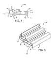
FIG. 4 depicts a cross-sectional view of the lineal member of FIG. 3.
FIG. 5 depicts a perspective view of the lineal member of FIGS. 3-4.
FIG. 6 depicts a cross-sectional view of the cap of FIG. 3.
FIG. 7 depicts a perspective view of the cap of FIGS. 3 and 6.
FIG. 8 is a perspective, exploded view of a corner key, including two parts.
FIG. 9 is a side view of an assembled corner key of FIG. 8.
FIG. 10 depicts a cross-sectional view of a different lineal member for a use in a frame of a casement window.
FIG. 11 depicts a cross-sectional view of another lineal member for a use in a frame of a picture window.
FIG. 12 depicts a cross-sectional view of another lineal member for use in a frame of a double hung window.
DETAILED DESCRIPTION OF PARTICULAR EMBODIMENTS
The systems and methods described herein related generally to joining frame members together to form frame assemblies using corner keys which fit inside of the ends of the frame members. More particularly, the systems and methods relate to use of frame members having uniform cross-sections such as those formed by pultrusion or extrusion.
In some embodiments, the frame assembly described herein provides a high level of thermal insulation by virtue of having two or three or sometimes four enclosed longitudinal cavities defined within each frame member. In one embodiment, the frame assembly includes one or more corner keys which are positioned adjacent to an outer perimeter of the assembled frame. In some embodiments, the frame member configuration permits insertion of the corner keys without any milling, that is, without removing any material from the interior of the frame member. In one embodiment, a corner key cavity extends across at least 60% of a depth of a frame member.
In some embodiments, the frame assembly system includes a cavity for a corner key that is defined between a lineal member and a cap. In some embodiments, this corner key cavity is located adjacent to an outer perimeter of the assembled frame. This position of the corner key improves the strength and design pressure of the assembled frame.
In the FIGS., various embodiments are illustrated. Like numbers refer, where appropriate, to like parts throughout the several views.
Now referring to FIG. 1, an exploded view of a frame assembly is illustrated including four frame members 10 and four corner keys 14. FIG. 2 shows an assembled frame 16 including the four frame members 10. The corner keys are not visible in FIG. 2 because each corner key 14 fits within the interior cavities of two adjacent frame members 10 to form a corner joint. The frame 16 defines an inner perimeter 18 and an outer perimeter 20. The opening 22 defined by the frame's inner perimeter 18 may be configured to mate with a window sash. The sash or the opening 22 may hold a pane of glass, an insulating glass unit, other transparent or translucent material, or a sheet.
The concepts related to frame members and assembly methods described herein are sometimes described in the context of windows. However, the same concepts apply to joining other structural or architectural elements at a corner joint. Many of the embodiments described herein have four frame members forming a frame assembly. However, it is also possible to apply the concepts described herein to an assembly that has two frame members, three frame members, five frame members, six frame members, and other numbers of frame members. Where a frame assembly does not from a closed perimeter, such as where there are two frame linear members at right angles to each other, the inner perimeter can be defined on the side of the frame assembly that has an angle between the frame members of less than 180 degrees. The outer perimeter can be defined on the side of the frame assembly that has an angle between frame members of greater than 180 degrees.
The frames of FIGS. 1-2 are rectangular frames. However, it is also possible to apply the frame assembly concepts described herein to non-rectangular frames, such as trapezoidal window frames, half-circle window frames, and other window frames, as will be discussed further herein.
Now referring to FIG. 1, corner keys 14 are configured with legs that extend into and fit within the hollow profiles of the frame members 10 to join the ends of the frame members 10 together. Adhesives can then be injected into the corners through specially designed passages to bond the corner keys 14 within the frame members 10 and thereby to secure the ends of the frame members 10 permanently together. In one embodiment, the adhesive is a two-part adhesive. The adhesive is selected to be compatible with the material of the frame member 10 and the material of the corner key 14. One example of a two-part adhesive is NovaGard 900-200 Corner Key Bonding Adhesive, available from NovaGard Solutions, Cleveland, Ohio, which is compatible with the resins in a fiberglass frame member 10 and compatible with a corner key 14 made of acrylonitrile-butadiene-styrene (ABS). In one embodiment, the adhesive when cured forms a polymer. In one embodiment, a hot melt adhesive is injected at the corners. In one embodiment, a thermoplastic adhesive is injected at the corners.
Now referring to FIG. 3, a cross-sectional view of a frame member 10 is illustrated. The frame member 10 includes two components: a lineal member 40 and a cap 42. The lineal member 40 is also illustrated in FIGS. 4 and 5. The cap 42 is also illustrated in FIGS. 6 and 7.
Referring to FIG. 3, the cap 42 attaches to the lineal member 40 by a snap-fit attachment. A cavity 44 is formed by the attachment of the cap 42 to the lineal member 40. The cavity 44 is configured to receive one leg of the corner key 14 and is referred to as the corner key cavity 44. An inner first side 43 of the frame member 10 will define the inner perimeter 18 in the assembled frame 16, while the opposite outer second side 45 of the frame member 10 will define the outer perimeter 20 in the assembled frame 16 (See FIG. 2). The corner key cavity 44 is adjacent to the outer first side 45 of the frame member 10 that will define the outer perimeter 20 of the frame. This position increases the strength of the assembled frame compared to other positions of the corner key 14.
The corner key cavity 44 is a longitudinal cavity that extends along the entire length of the frame member 10. The corner key cavity 44 is bounded by a closed perimeter. The presence of this bounded cavity improves the insulation value of the frame member 10.
In some embodiments, the corner key cavity 44 extends across most of the depth dimension of the frame member, thereby further increasing the strength of the assembled frame 16. The depth dimension D of the frame member 10 is measured from an outside surface 146 of an outer first side 46 to an outside surface 148 of an opposite inner second side 48 of the frame member 10. The depth extension E of the corner key 14 is measured across each of the legs 86, 88 of the corner key 14 as shown in FIG. 8. The corner key 14 fits snugly into the corner key cavity 44. As a result, another way to measure the depth extension E of the corner key 14 is by measuring the inside dimension of the corner key cavity 44. As shown in FIG. 6, the depth extension E of the corner key 14 can also be measured from an inside surface 160 of a first protrusion 60 to an inside surface 161 of a second protrusion 61.
In some embodiments, the corner key cavity extends across at least about 60% of the depth of the frame member. In some embodiments, the corner key cavity extends across at least about 65% of the depth of the frame member. In some embodiments, the corner key cavity extends across at least about 67% of the depth of the frame member. In some embodiments, the corner key cavity extends across at least about 70% of the depth of the frame member. In some embodiments, the corner key cavity extends across at least about 72% of the depth of the frame member. In some embodiments, the corner key cavity extends across at least about 75% of the depth of the frame member. In the embodiment of FIGS. 3-5, the corner key extends across about 70% of the depth of the frame member. In the embodiment of FIG. 10, the corner key extends across about 67% of the depth of the frame member. In the embodiment of FIG. 11, the corner key extends across about 75% of the depth of the frame member. In the embodiment of FIG. 12, the corner key extends across about 71% of the depth of the frame member.
The assembled frame includes a first face and a second face. One of the faces is facing the viewer in FIG. 2. For example, the first face might be the exterior face of a building's window, while the second face is the interior face of a building's window. Referring to FIG. 3, the first side 46 of the frame member 10 will define part of the first face while the opposite second side 48 of the frame member 10 will define the second face.
In one embodiment, the lineal member 40 defines a first interior cavity 50 and a second interior cavity 52. The inclusion of multiple interior cavities 50, 52 increases the insulating properties of the frame 16. The interior cavities 50, 52 are longitudinal cavities that extend along the length of the frame member 10. In one embodiment, the lineal member 40 further defines a third interior cavity 53. The third interior cavity 53 is adjacent to one side 48, while the first interior cavity is adjacent to the other side 46. The second interior cavity 52 is positioned between the first and third interior cavities 50, 53.
In one embodiment, the lineal member defines at least one interior cavity and an open area for a corner key cavity. In one embodiment, the lineal member defines at least two interior cavities and an open area for a corner key cavity. In one embodiment, the lineal member defines at least three interior cavities and an open area for a corner key cavity. In one embodiment, the lineal member defines at least four interior cavities and an open area for a corner key cavity.
The lineal member 40 and the cap 42 each include attachment structures that interact with each other to cause a snap-fit attachment of the cap 42 to the lineal member 40. The lineal member 40 shown in FIGS. 4 and 5 includes an exterior surface 54 and first attachment structures 56, 57 defined by the exterior surface 54. In one embodiment, the first attachment structure includes two protrusions 56, 57 including nubs 58 near the ends of the protrusions 56, 57.
Mating attachment structures 60, 61 on the cap 42 are seen in FIGS. 6 and 7, and can also be referred to as protrusions 60, 61 defining nubs 62 at their ends. As seen in FIG. 3, the first and second attachment structures 56, 57, 60, 61 are configured to lock together when brought into contact. The second attachment structures 60, 61 of the cap fit within the first attachment structures 56, 57 extending from the lineal member 40. The first and second attachment structures are longitudinal features that extend along the length of the lineal member 40 and cap 42, respectively.
In the embodiments of the FIGS., the attachment structures are two longitudinal protrusions with nub structures which lock into an attached position with two similar longitudinal protrusions. In some embodiments, the attachment structure of the lineal member and the attachment structure of the cap are connected by a snap-fit. A snap-fit refers to a connection between parts where mating parts exert a cam action, flexing until one part slips past a raised lip on another part. Other types of attachment structures are present in some embodiments.
FIG. 8 is an exploded perspective view of the two parts that make up the corner key 14 in one embodiment. The outer portion 82 attaches to the inner portion 84 using interlocking mechanical structures to form the corner key 14. By making the corner key 14 in two parts, ease of manufacturing is increased. Also, the two-part corner key 14 allows adhesive to flow between the inner portion 84 and outer portion 82. The corner key 14 of FIGS. 8 and 9 has been found to be structurally solid after the adhesive is injected and has cured.
FIG. 9 is a side view of one embodiment of the corner key 14, which includes a first leg 86 and a second leg 88 forming a 90 degree angle with the first leg 86. In other embodiments, the angle is not 90 degrees. In other embodiments, the angle between the legs is adjustable. During the assembly of a frame, the first leg 86 is inserted into the end of a corner key cavity 44 of a first frame member, while the second leg 88 is inserted into the end of a corner key cavity 44 of another frame member 10. The corner key 14 is dimensioned and configured so that it will fit tightly within the corner key cavities 44. As a result, the two frame members 10 are joined.
The corner key joint 90 is the portion of the corner key 14 where the two legs 86, 88 or two halves are connected. In one embodiment, the joint 90 of the corner key 14 is flexible and acts as a hinge. As a result, the angle between the first and second legs 86, 88 can vary as needed depending on the frame shape.
The corner key 14 includes channels and recesses for routing and retaining adhesive that is injected into the corner area after the corner key 14 is positioned within adjacent frame members 10. The adhesive improves the structural integrity of the joint. The corner key 14 can be made from a wide variety of materials including nylon and crylonitrile-butadiene-styrene (ABS). In one embodiment, the corner key 14 is made from a non-metallic material.
The corner key 14 is configured to fit tightly within the corner key cavity 44. A measured amount of adhesive is injected into the joint once the corner key 14 is in place. The corner key cavity 44 and the corner key 14 are designed to encourage the adhesive to flow along each leg 86, 88, up against the ramp structures at the ends of the legs, through openings in the corner key and to spaces between inner and outer portions 82, 84. Bumps on the sides of the legs 86, 88 are designed to fit snuggly into the corner key cavity 44. In one embodiment, adhesive fills all the cracks and crevices in the joint area.
In one embodiment, the frame members are cut from lineal stock. In one embodiment, the frame members are formed to the lengths needed for constructing a frame assembly. In some embodiments, the frame members define a substantially hollow profile, though the interior cavity is divided into multiple cavities by interior walls in some embodiments.
In one embodiment, the frame members are made of pultruded fiberglass material. In another embodiment, the frame members are made of an extruded thermoplastic composite material. One example of a thermoplastic composite materials includes wood and polymer. A product of an extrusion process can be referred to as an extrudate. An extrudate has a uniform cross-section along its length. The frame members, lineal members and cap can be extrudates. In one embodiment, the frame members are made of vinyl.
Both pultrusion and extrusion processes form long parts with a uniform or constant cross-sections along their lengths which are also referred to as lineals. The lineal may be miter cut or cut in other ways at their ends to allow formation of an attractive joint with another lineal. The lineals may be cut to form the appearance of a mortise and tenon joint, while still using a corner key to join two frame members.
A few examples of profiles for window assemblies are illustrated herein, but it will be understood that many different further features may be present on the profiles. The invention disclosed and claimed herein is applicable to all such profiles.
FIGS. 10 and 11 depict cross-sectional views of different lineal members 100, 102 for a use in a frame of a casement window and a picture window, respectively. Like the lineal member 40 described with respect to FIGS. 4-5, the lineal members 100, 102 are configured for attachment to a cap. In one embodiment, each of the lineal members 100, 102 are configured for attachment to the same cap 42 which attaches to lineal member 40 in at least one embodiment. This reduces the number of different parts to be inventoried in manufacturing environment for frames. It also reduces the tooling expense and complexity of the manufacturing process. In addition, it is possible for a single corner key configuration to be used with multiple lineal members and frame types because the cap forming the corner key cavity is consistent across the various designs.
Lineal member 100 of FIG. 10 defines four interior cavities 170, 172, 174 and 176, in addition to defining a corner key cavity area 178. The corner key cavity area 178 is defined by two protrusions 180, 182 which serve as attachment structures for attaching to the cap 42. The depth D of the lineal member 100, which will also be the depth D of the resulting frame member including the cap 42, is shown in FIG. 10. The depth D of the lineal member 100 is measured from an outside surface 184 of a first side to an outside surface 186 of an opposite second side of the lineal member 100.
Lineal member 102 of FIG. 11 has three interior cavities 190, 192, 194 in addition to the corner key cavity area 196. The third interior cavity 194 is adjacent to one side 208, while the first interior cavity 190 is adjacent to the other side 206. The second interior cavity 192 is positioned between the first and third interior cavities 190, 194. The corner key cavity area 196 is defined by two protrusions 198, 200 which serve as attachment structures for attaching to the cap 42. The depth D of the lineal member 102, which is also the depth D of the resulting frame member including the cap 42, is shown in FIG. 11. The depth D of the lineal member 102 is measured from an outside surface 206 of a first side to an outside surface 208 of an opposite second side of the lineal member 102.
FIG. 12 shows a cross-sectional view of another embodiment of a frame member 104. Like lineal member 40, frame member 104 has three interior cavities 150, 152, 153 in addition to the corner key cavity 144. The third interior cavity 153 is adjacent to one side of the frame member, while the first interior cavity 150 is adjacent to the opposite of the frame member 104. The second interior cavity 152 is positioned between the first and third interior cavities 150, 153. The corner key cavity 144 is adjacent to the outer perimeter of the frame assembly. A frame assembly is formed by joining two or more of the frame members 104. The corner key cavity 144 extends across more than 60% of the depth of the frame member 104. The corner key cavity 144 is an integral part of the frame member profile. The frame member 104 is a unitary member. In one embodiment, the frame member 104 is formed by extruding a vinyl frame member 104.
In one embodiment, the frame member defines at least one interior cavity and a corner key cavity. In one embodiment, the frame member defines at least two interior cavities and a corner key cavity. In one embodiment, the frame member defines at least three interior cavities and a corner key cavity. Individual features or groups of features described herein with respect to the frame members or lineal members can also be combined with the lineal member 104.
There are many possible embodiments of methods of forming a frame assembly. In one embodiment, stock members such as the lineal members, the caps and/or frame assemblies are formed using pultrusion or extrusion so that each member has a uniform cross section over its length. In one embodiment, the members are formed by pultrusion of fiberglass.
In one embodiment, fairly long stock frame members and frame member components are formed by extrusion or pultrusion. The stock members can be formed in a standard length, such as sixteen foot lengths. In one embodiment, the frame members and frame member components are formed in the specific lengths that are needed for making frame assemblies.
In some embodiments, each frame member has a uniform cross section along its length. The cavities that are defined within the frame member will also have uniform cross sections across their lengths. Each frame member includes a first end and a second end. The first and second ends are angled ends in one embodiment. In some embodiments, the length of the frame member, lineal member or cap which extends between the angled ends has a uniform cross section.
In some embodiments, the frame members and frame member components are painted or laminated after formation. The paint coating or lamination covering can provide increased durability and aesthetic changes to the frame members.
In one embodiment, formation of a cap stock member can be followed by attaching a cap stock member to a lineal stock member to form a stock frame assembly. In other embodiments, the frame member is formed as a unitary structure without any need to attach a cap.
To construct a particular frame assembly from the stock frame members, the next step is to cut the stock frame members to the appropriate length with the appropriate miter cut at the ends. Another step is performance of routing operations such as forming adhesive injection holes, forming venting holes, forming window balance knock-outs and other routing operations as appropriate for the type of window. Hardware may also be added if appropriate.
Next, the frame members are brought together using a clamping system, with a corner key positioned at each corner. One leg or one half of the corner key is inserted into one end of a corner key cavity of a frame member. The other leg or half if the corner key is inserted into one end of a corner key of another frame member. Then, adhesive is injected into the joint areas. In one embodiment, each joint area includes two injection holes. Each injection hole is located near one of the legs of the corner key, on opposite sides of the joint 90 of the corner key and close to the joint of the corner key. In this embodiment, two venting holes are also provided close to the joint of the corner key.
In one embodiment, adhesive is used at the joints to enhance the structural integrity of the completed frame. In some embodiments, separate mechanical fasteners are used at the joints, either alone or in addition to adhesive. In one embodiment, the joint is secured with adhesive without the use of any separate mechanical fasteners. When the frame members are formed of hollow profile material as in the preferred embodiments, the ends of the lineals are sometimes mitered. In addition to or instead of adhesive and fasteners, the mitered ends can be joined securely together by other methods, for example, by sonic welding.
In some embodiments, vinyl frame members are used in combination with ultrasonic bonding of the frame members to form a corner joint. However, it may be desirable to touch-up the appearance of the vinyl if the vinyl laminate is modified by the ultrasonic welding. The use of corner keys and adhesive to form the joint reduces the likelihood of performing a touch-up step.
Design pressure (DP) is a metric of a window's strength and is measured in pounds per square foot (pst). Measurements techniques for DP are further described in ASTM E1300, titled “Standard Practice for Determining Load Resistance of Glass in Buildings.” Windows according to the discussion herein can have a DP of at least 50 psf, a DP of at least 70 psf and DP of 90 psf in various embodiments.
Thermal performance of a window can be improved by using the frame described herein. The U-factor is a term that is used to quantify heat transfer. The units for U-factor are British thermal unit (Btu) per hour per square foot of area per degree Fahrenheit temperature difference. The computer programs Therm 5 and Window 5 are industry-standard computer tools used to simulate heat flow through the edge of the glass and window frame regions and through the center of glass. These programs also sum up the respective contribution of each component to determine the U-factor for the whole window. These computer programs were developed by the Lawrence Berkeley National Laboratory. Using these computer programs, testing was performed using the example of FIG. 3 where the frame is constructed of fiberglass, the corner key is constructed of ABS, and NovaGard 900-200 Corner Key Adhesive. AU-factor of 0.22 was achieved. An R5 rating is a sought after level of thermal insulation for a window. An R5 rating is achieved if a fixed unit has a U-factor of 0.20 or less. An R5 rating is achieved for an operating window unit where the U-factor is 0.22 or less. Embodiments of the frame assembly provided herein achieve an R5 rating.
An example of a system and method for forming a frame assembly has been described, but those of skill in the art will be aware of many options and alternatives to the equipment and method steps described that can be used.
Various embodiments are described in detail with reference to the drawings, wherein like reference numerals represent like parts and assemblies throughout the several views. Reference to various embodiments does not limit the scope of the claims attached hereto. Additionally, any examples set forth in this specification are not intended to be limiting and merely set forth some of the many possible embodiments for the appended claims.

Claims (18)

I claim:
1. A structural frame member, comprising:
a body portion having an inner section defining a plurality of axially extending passages and an outer section defining a key passage area, wherein the key passage area defines an axially extending, transversely open channel, wherein the transversely open channel overlies at least a portion of one of the plurality of axially extending passages defined by the inner section; and
a cap portion configured for engagement with the outer section of the body portion over the channel defined by the key passage area of the body portion, wherein, when the cap portion is engaged with the body portion over the channel defined by the key passage area, the cap portion and the channel defined by the key passage area of the body portion cooperate to define an enclosed key passage having an axially facing open end, wherein the key passage extends inwardly from the axially facing open end, wherein at least an end portion of the key passage adjacent the axially facing open end is unobstructed by the cap portion and configured to axially receive a portion of a corner key.
2. The structural frame member of claim 1, wherein the key passage area of the body portion is defined by a pair of spaced apart protrusions that extend from a wall forming a part of the body portion, wherein the protrusions in part define the channel, and wherein the cap portion is configured for engagement with the pair of spaced apart protrusions.
3. The structural frame number of claim 2, wherein the cap portion and the pair of spaced apart protrusions include snap-type engagement structure that secures the cap portion to the pair of spaced apart protrusions upon application of a transversely directed force to the cap portion.
4. The structural frame member of claim 2, wherein the outer and inner sections of the body portion are separated at least in part by the wall from which the spaced apart protrusions extend.
5. The structural frame member of claim 4, wherein the body portion defines a depth, and wherein the enclosed key passage defined by the key passage area of the body portion and the cap portion extends across a majority of the depth of the body portion.
6. The structural frame member of claim 2, wherein the enclosed key passage defined by the key passage area of the body portion and the cap portion overlies at least a pair of the axially extending passages defined by the body portion.
7. A structural frame assembly, comprising:
at least a pair of structural frame members, wherein each frame member comprises: a body portion having an inner section defining a plurality of axially extending passages and an outer section defining a key passage area, wherein the key passage area defines an axially extending, transversely open channel, wherein the transversely open channel overlies at least a portion of one of the plurality of axially extending passages defined by the inner section; and a cap portion engaged with the outer section of the body portion over the channel defined by the key passage area, wherein the cap portion and the channel defined by the key passage area of the body portion cooperate to define an enclosed key passage having an axially facing open end, wherein the key passage extends inwardly from the axially facing open end, wherein at least an end portion of the key passage adjacent the axially facing open end is unobstructed by the cap portion; wherein the axially facing open ends of the key passages of the pair of structural frame members face each other; and
a corner key extending through the facing open ends of the structural frame members and into the key passages of the structural frame members, wherein engagement of the corner key within the key passages of the pair of structural frame members secures the pair of structural frame members together.
8. The structural frame assembly of claim 7, wherein the structural frame members comprise window frame members.
9. The structural frame assembly of claim 8, wherein the key passage area of the body portion of each structural frame member is defined by a pair of spaced apart protrusions that extend from a wall forming a part of the body portion of the structural frame member, wherein the protrusions in part define the channel, and wherein the cap portion is configured for engagement with the pair of spaced apart protrusions.
10. The structural frame assembly of claim 9, wherein the cap portion and the pair of spaced apart protrusions include snap-type engagement structure that secures the cap portion to the pair of spaced apart protrusions upon application of a transversely directed force to the cap portion.
11. The structural frame assembly of claim 9, wherein the outer and inner sections of the body portion of each structural frame member are separated at least in part by the wall from which the spaced apart protrusions extend.
12. The structural frame assembly of claim 11, wherein the body portion of each structural frame member defines a depth, and wherein the enclosed key passage defined by the key passage area of the body portion and the cap portion of each structural frame member extends across a majority of the depth of the body portion.
13. The structural frame assembly of claim 9, wherein the enclosed key passage defined by the key passage area of the body portion of each structural frame member and the associated cap portion overlie at least a pair of the axially extending passages defined by the body portion of each structural frame member.
14. The structural frame assembly of claim 7, wherein a plurality of structural frame members and corner keys are secured together to define an enclosed frame assembly.
15. A method of assembling a structural frame member, comprising the acts of:
providing a body portion having an outer section defining a plurality of axially extending passages and an inner section defining a key passage area, wherein the key passage area defines an axially extending, transversely open channel, wherein the transversely open channel overlies at least a portion of one of the plurality of axially extending passages defined by the inner section; and
engaging a cap portion with the key passage area over the channel defined by the key passage area, wherein, when the cap portion is engaged with the body portion over the channel defined by the key passage area, the cap portion and the channel defined by the key passage area of the body portion cooperate to define an enclosed key passage having an axially facing open end, wherein the key passage extends inwardly from the axially facing open end, wherein at least an end portion of the key passage adjacent the axially facing open end is unobstructed by the cap portion and configured to axially receive a portion of a corner key.
16. The method of claim 15, wherein the key passage area is defined at least in part by a pair of protrusions on the body portion, wherein the protrusions in part define the channel, and wherein the act of engaging the cap portion with the key passage area is carried out by snap fitting the cap portion and the pair of protrusions together.
17. The method of claim 15, further comprising the act of providing a plurality of the structural frame members, wherein the cap portion and the key passage area of the body portion of each structural frame member cooperate to define an enclosed key passage, wherein the axially facing open ends of the key passages of each pair of the frame members face each other;
positioning the ends of the pair frame members adjacent each other; and
engaging a corner key with the corner key passages of the pair of structural frame members, wherein the corner key extends through the axially facing open ends of the key passages of the pair of structural frame members and into the key passages of the structural frame members, wherein engagement of the corner key within the key passages of each adjacent pair of structural frame members secures the structural frame members together.
18. The method of claim 17, further comprising the act of placing adhesive in the corner key passages of the pair of structural frame members, wherein the adhesive interacts with the corner key and the structural frame members to assist in securing the pair of structural frame members together.
US13/604,037 2011-11-03 2012-09-05 Structural frame member having a capped corner key passage Active US8511011B2 (en)

Priority Applications (1)

Application Number Priority Date Filing Date Title
US13/604,037 US8511011B2 (en) 2011-11-03 2012-09-05 Structural frame member having a capped corner key passage

Applications Claiming Priority (3)

Application Number Priority Date Filing Date Title
US201161555384P 2011-11-03 2011-11-03
US201161558919P 2011-11-11 2011-11-11
US13/604,037 US8511011B2 (en) 2011-11-03 2012-09-05 Structural frame member having a capped corner key passage

Publications (2)

Publication Number Publication Date
US20130111846A1 US20130111846A1 (en) 2013-05-09
US8511011B2 true US8511011B2 (en) 2013-08-20

Family

ID=48222525

Family Applications (3)

Application Number Title Priority Date Filing Date
US13/604,037 Active US8511011B2 (en) 2011-11-03 2012-09-05 Structural frame member having a capped corner key passage
US13/655,541 Expired - Fee Related US8596017B2 (en) 2011-11-03 2012-10-19 Frame members, corner key and assembly method
US14/061,955 Expired - Fee Related US8683694B1 (en) 2011-11-03 2013-10-24 Method of forming a frame assembly

Family Applications After (2)

Application Number Title Priority Date Filing Date
US13/655,541 Expired - Fee Related US8596017B2 (en) 2011-11-03 2012-10-19 Frame members, corner key and assembly method
US14/061,955 Expired - Fee Related US8683694B1 (en) 2011-11-03 2013-10-24 Method of forming a frame assembly

Country Status (2)

Country Link
US (3) US8511011B2 (en)
CA (1) CA2794488C (en)

Cited By (3)

* Cited by examiner, † Cited by third party
Publication number Priority date Publication date Assignee Title
US20130205706A1 (en) * 2011-11-03 2013-08-15 Proformance Manufacturing, Inc. Frame assembly having a corner key
US8683694B1 (en) 2011-11-03 2014-04-01 James Hardie Technology Limited Method of forming a frame assembly
US20150121788A1 (en) * 2013-11-05 2015-05-07 Soon Seok Kim Prefabricated structure of composite window/door apparatus using different frame materials

Families Citing this family (12)

* Cited by examiner, † Cited by third party
Publication number Priority date Publication date Assignee Title
US11419437B2 (en) 2010-05-14 2022-08-23 Mcs Industries, Inc. Hanging apparatus
US20140165492A1 (en) * 2012-09-25 2014-06-19 Harold S. Friedman Method and system for modular panels and their installation
MX367747B (en) 2013-04-13 2019-09-04 Milgard Mfg Inc Fenestration trim assembly.
US20150027350A1 (en) * 2013-07-24 2015-01-29 Nick T. Castillo Outdoor kitchen unit
US9874052B2 (en) * 2016-01-25 2018-01-23 Gilkey Window Company Window mainframe component for emergency escape and rescue opening windows
CA2947994A1 (en) * 2016-11-08 2018-05-08 Portes Patio Novatech Inc. Clamping device for energy efficient frames
US10604988B1 (en) 2017-01-30 2020-03-31 Andersen Corporation Adaptable fenestration frame members and methods
GB2586515B (en) * 2019-08-23 2022-12-28 The Metal Window Co Ltd Metal window frame construction
US20210355744A1 (en) * 2020-05-15 2021-11-18 Vinyl Window Designs Sash apparatus and method of making same
CN112412252A (en) * 2020-11-25 2021-02-26 湖南潇安安全科技有限公司 Window sash structure
US11939811B2 (en) 2021-09-10 2024-03-26 Andersen Corporation Sill corner brackets for coastal impact resistant fenestrations
CN114411741B (en) * 2022-01-19 2023-12-19 三峡大学 Pressure grouting device and method for pile hole protection wall

Citations (6)

* Cited by examiner, † Cited by third party
Publication number Priority date Publication date Assignee Title
US3429602A (en) * 1967-04-26 1969-02-25 Alusuisse Welded light-metal corner construction
US4164105A (en) * 1974-12-20 1979-08-14 Tenneco Chemicals, Inc. Frame structure
US4831804A (en) * 1987-09-17 1989-05-23 Thermal Profiles, Inc. Window frame apparatus
US5187886A (en) * 1991-09-09 1993-02-23 Wu Chii Chong Picture frame
US20050210777A1 (en) * 2004-03-11 2005-09-29 Baughn Antony L Integrated storm shutter
US7174691B2 (en) * 2000-10-31 2007-02-13 De Garay Arellano David Antoni Aluminum profile system for placing doors, windows and partition walls

Family Cites Families (32)

* Cited by examiner, † Cited by third party
Publication number Priority date Publication date Assignee Title
US2792918A (en) 1955-07-05 1957-05-21 Detroit Gasket & Mfg Company Knock-down metal frame construction
US3592289A (en) * 1968-09-06 1971-07-13 Conwed Corp Freestanding acoustical space divider
US3782054A (en) * 1971-09-15 1974-01-01 Capitol Prod Corp Corner angle for windows
US3835613A (en) 1973-03-26 1974-09-17 Carter Waters Corp Sign frame assembly
US4624091A (en) * 1984-07-20 1986-11-25 Winchester Industries, Inc. Thermally insulated window sash construction
US5603585A (en) * 1994-05-17 1997-02-18 Andersen Corporation Joint structure and method of manufacture
US5622017A (en) 1994-10-19 1997-04-22 Andersen Corporation Window sash
US5491940A (en) 1994-10-19 1996-02-20 Andersen Corporation Method and apparatus for mounting window on angled sill
US5687533A (en) 1995-06-15 1997-11-18 Andersen Corporation Method and apparatus for connecting window frame segments
JPH09165871A (en) * 1995-12-15 1997-06-24 Ado Space Kk Frame member
US5806256A (en) * 1996-03-26 1998-09-15 Byrne; John F. Modular glazing system
US6067760A (en) * 1998-01-26 2000-05-30 Patio Enclosures, Inc. Corner bracket for doors and windows
US6047514A (en) * 1998-09-04 2000-04-11 Quanex Corporation Window component and method of manufacture
BE1012394A3 (en) 1998-09-29 2000-10-03 Brochez Alain Corner connection and method for manufacturing of such area connection and plug-in brackets to such area link to realize.
US6513288B1 (en) 1999-02-26 2003-02-04 Steelcase Development Corporation Window assembly for partitions
WO2000065188A1 (en) 1999-04-28 2000-11-02 Andersen Corporation Assembly structure and method involving insert structure with inlet port, adhesive channel portion and adhesive bonding area
US6550210B1 (en) * 2000-05-04 2003-04-22 Certainteed Corporation Window frame member with channel formed within the member for accepting siding or sheathing
US6679013B2 (en) 2001-11-15 2004-01-20 Sashlite, Llc Window assembly with hinged components
US6868648B2 (en) 2002-04-04 2005-03-22 Bowmead Holdings Inc. Fenestration sealed frame, insulating glazing panels
CA2384213C (en) * 2002-04-30 2008-10-07 Tetsuya Kobayashi Sliding door assembly
US6886300B2 (en) * 2002-08-22 2005-05-03 Wayne-Dalton Corp. Tensioned fabric storm protection panel
CA2507108C (en) 2002-11-13 2010-05-11 Visionwall Corporation Energy efficient window
US7207636B2 (en) * 2003-09-03 2007-04-24 I.D. Furniture Systems, Inc. Modular cabinet system
US20050081981A1 (en) 2003-10-16 2005-04-21 Heikkila Kurt E. Groove glazed window sash and fabrication method
TW200619486A (en) * 2004-07-15 2006-06-16 Kimio Akutsu Defrosting and heat-insulating device for window
US7634880B2 (en) * 2006-03-17 2009-12-22 Milgard Manufacturing, Inc. Foam seal frame corner joint and method of manufacture
DE102006059854B4 (en) 2006-12-15 2010-04-01 Technoform Caprano Und Brunnhofer Gmbh & Co. Kg Reinforced plastic profile for window, door and façade elements
ITBO20070243A1 (en) * 2007-04-03 2008-10-04 Gsg Int Spa ACCESSORY FOR PROFILES FOR SLIDING DOORS.
USD618363S1 (en) 2009-03-25 2010-06-22 SureView, Inc. Window
USD618822S1 (en) 2009-08-18 2010-06-29 SureView, Inc. Window
US8490347B2 (en) * 2011-05-05 2013-07-23 Milgard Manufacturing Incorporated Corner joint for a window or door frame
US8511011B2 (en) 2011-11-03 2013-08-20 James Hardie Technology Limited Structural frame member having a capped corner key passage

Patent Citations (7)

* Cited by examiner, † Cited by third party
Publication number Priority date Publication date Assignee Title
US3429602A (en) * 1967-04-26 1969-02-25 Alusuisse Welded light-metal corner construction
US4164105A (en) * 1974-12-20 1979-08-14 Tenneco Chemicals, Inc. Frame structure
US4831804A (en) * 1987-09-17 1989-05-23 Thermal Profiles, Inc. Window frame apparatus
US5187886A (en) * 1991-09-09 1993-02-23 Wu Chii Chong Picture frame
US7174691B2 (en) * 2000-10-31 2007-02-13 De Garay Arellano David Antoni Aluminum profile system for placing doors, windows and partition walls
US20050210777A1 (en) * 2004-03-11 2005-09-29 Baughn Antony L Integrated storm shutter
US7677003B2 (en) * 2004-03-11 2010-03-16 Baughn Antony L Integrated storm shutter including latch pin corner connection and/or center louver support rail

Cited By (5)

* Cited by examiner, † Cited by third party
Publication number Priority date Publication date Assignee Title
US20130205706A1 (en) * 2011-11-03 2013-08-15 Proformance Manufacturing, Inc. Frame assembly having a corner key
US8683694B1 (en) 2011-11-03 2014-04-01 James Hardie Technology Limited Method of forming a frame assembly
US8857129B2 (en) * 2011-11-03 2014-10-14 Proformance Maufacturing, Inc. Frame assembly having a corner key
US20150121788A1 (en) * 2013-11-05 2015-05-07 Soon Seok Kim Prefabricated structure of composite window/door apparatus using different frame materials
US9528315B2 (en) * 2013-11-05 2016-12-27 Ida Co., Ltd. Prefabricated structure of composite window/door apparatus using different frame materials

Also Published As

Publication number Publication date
US8683694B1 (en) 2014-04-01
US20130111847A1 (en) 2013-05-09
CA2794488A1 (en) 2013-05-03
CA2794488C (en) 2020-01-07
US20130111846A1 (en) 2013-05-09
US8596017B2 (en) 2013-12-03

Similar Documents

Publication Publication Date Title
US8511011B2 (en) Structural frame member having a capped corner key passage
US8857129B2 (en) Frame assembly having a corner key
CA2202046C (en) Joint structure and method of manufacture
US7937904B2 (en) Corner joint for pultruded window frame
US9238934B2 (en) Door jamb member, door jamb assembly incorporating same and kit therefor
US8057120B2 (en) Corner joining of structural members
JPH02115489A (en) Frame assembly of door, window, etc.
US6866081B1 (en) Exterior door or window having extruded composite frame
US20050115178A1 (en) Corner key for connecting profiles together and frame work assembly
KR101507484B1 (en) Windows and doors with high insulation for easy separation and manufacturing method thereof
US10036192B2 (en) Reinforced mull post assembly
US20090178361A1 (en) Method of fabricating frames for 'doors and the like from extruded compponents and reinforced frame of extruded components
US11781372B2 (en) Door assemblies with insulated glazing unit venting
US20140102035A1 (en) Brick mold assembly, connector for same and kit for assembly of same
KR100939115B1 (en) Sash bar suitable for insulating window units
CN111219123A (en) Method for manufacturing composite material window
KR100848368B1 (en) The double sliding-doorframe
GB2578909A (en) Bead assembly
GB2476264A (en) Two part frame assembly with insulated joint
GB2427428A (en) Composite door
CA2831991A1 (en) Brick mold assembly, and connector for same and kit for assembly of same
JPH04216793A (en) Frame member for housing fitting wherein anticipated width is variable
CA2600598A1 (en) Corner joining of structural members

Legal Events

Date Code Title Description
AS Assignment

Owner name: JAMES HARDIE TECHNOLOGY LIMITED, IRELAND

Free format text: ASSIGNMENT OF ASSIGNORS INTEREST;ASSIGNOR:EMANUEL, BRIAN A.;REEL/FRAME:028935/0106

Effective date: 20120906

STCF Information on status: patent grant

Free format text: PATENTED CASE

CC Certificate of correction
AS Assignment

Owner name: JAMES HARDIE TECHNOLOGY LIMITED, IRELAND

Free format text: ASSIGNMENT OF ASSIGNORS INTEREST;ASSIGNOR:BERANEK, GERALD D.;REEL/FRAME:034465/0850

Effective date: 20141126

CC Certificate of correction
FPAY Fee payment

Year of fee payment: 4

MAFP Maintenance fee payment

Free format text: PAYMENT OF MAINTENANCE FEE, 8TH YEAR, LARGE ENTITY (ORIGINAL EVENT CODE: M1552); ENTITY STATUS OF PATENT OWNER: LARGE ENTITY

Year of fee payment: 8