EP1970516B1 - Vorrichtung zur Kontrolle der Sicherheit eines Rahmens während dessen Bewegung - Google Patents
Vorrichtung zur Kontrolle der Sicherheit eines Rahmens während dessen Bewegung Download PDFInfo
- Publication number
- EP1970516B1 EP1970516B1 EP08004338.3A EP08004338A EP1970516B1 EP 1970516 B1 EP1970516 B1 EP 1970516B1 EP 08004338 A EP08004338 A EP 08004338A EP 1970516 B1 EP1970516 B1 EP 1970516B1
- Authority
- EP
- European Patent Office
- Prior art keywords
- wing
- movement
- collision
- electronic accelerometer
- moving
- Prior art date
- Legal status (The legal status is an assumption and is not a legal conclusion. Google has not performed a legal analysis and makes no representation as to the accuracy of the status listed.)
- Active
Links
Images

Classifications
-
- E—FIXED CONSTRUCTIONS
- E05—LOCKS; KEYS; WINDOW OR DOOR FITTINGS; SAFES
- E05F—DEVICES FOR MOVING WINGS INTO OPEN OR CLOSED POSITION; CHECKS FOR WINGS; WING FITTINGS NOT OTHERWISE PROVIDED FOR, CONCERNED WITH THE FUNCTIONING OF THE WING
- E05F15/00—Power-operated mechanisms for wings
- E05F15/40—Safety devices, e.g. detection of obstructions or end positions
- E05F15/41—Detection by monitoring transmitted force or torque; Safety couplings with activation dependent upon torque or force, e.g. slip couplings
-
- E—FIXED CONSTRUCTIONS
- E05—LOCKS; KEYS; WINDOW OR DOOR FITTINGS; SAFES
- E05D—HINGES OR SUSPENSION DEVICES FOR DOORS, WINDOWS OR WINGS
- E05D15/00—Suspension arrangements for wings
- E05D15/36—Suspension arrangements for wings moving along slide-ways so arranged that one guide-member of the wing moves in a direction substantially perpendicular to the movement of another guide member
- E05D15/38—Suspension arrangements for wings moving along slide-ways so arranged that one guide-member of the wing moves in a direction substantially perpendicular to the movement of another guide member for upwardly-moving wings, e.g. up-and-over doors
-
- E—FIXED CONSTRUCTIONS
- E05—LOCKS; KEYS; WINDOW OR DOOR FITTINGS; SAFES
- E05F—DEVICES FOR MOVING WINGS INTO OPEN OR CLOSED POSITION; CHECKS FOR WINGS; WING FITTINGS NOT OTHERWISE PROVIDED FOR, CONCERNED WITH THE FUNCTIONING OF THE WING
- E05F15/00—Power-operated mechanisms for wings
- E05F15/40—Safety devices, e.g. detection of obstructions or end positions
-
- E—FIXED CONSTRUCTIONS
- E05—LOCKS; KEYS; WINDOW OR DOOR FITTINGS; SAFES
- E05D—HINGES OR SUSPENSION DEVICES FOR DOORS, WINDOWS OR WINGS
- E05D15/00—Suspension arrangements for wings
- E05D15/40—Suspension arrangements for wings supported on arms movable in vertical planes
- E05D15/44—Suspension arrangements for wings supported on arms movable in vertical planes with pivoted arms and vertically-sliding guides
- E05D15/445—Suspension arrangements for wings supported on arms movable in vertical planes with pivoted arms and vertically-sliding guides specially adapted for overhead wings
-
- E—FIXED CONSTRUCTIONS
- E05—LOCKS; KEYS; WINDOW OR DOOR FITTINGS; SAFES
- E05Y—INDEXING SCHEME ASSOCIATED WITH SUBCLASSES E05D AND E05F, RELATING TO CONSTRUCTION ELEMENTS, ELECTRIC CONTROL, POWER SUPPLY, POWER SIGNAL OR TRANSMISSION, USER INTERFACES, MOUNTING OR COUPLING, DETAILS, ACCESSORIES, AUXILIARY OPERATIONS NOT OTHERWISE PROVIDED FOR, APPLICATION THEREOF
- E05Y2400/00—Electronic control; Electrical power; Power supply; Power or signal transmission; User interfaces
- E05Y2400/10—Electronic control
- E05Y2400/32—Position control, detection or monitoring
- E05Y2400/322—Position control, detection or monitoring by using absolute position sensors
- E05Y2400/326—Position control, detection or monitoring by using absolute position sensors of the angular type
-
- E—FIXED CONSTRUCTIONS
- E05—LOCKS; KEYS; WINDOW OR DOOR FITTINGS; SAFES
- E05Y—INDEXING SCHEME ASSOCIATED WITH SUBCLASSES E05D AND E05F, RELATING TO CONSTRUCTION ELEMENTS, ELECTRIC CONTROL, POWER SUPPLY, POWER SIGNAL OR TRANSMISSION, USER INTERFACES, MOUNTING OR COUPLING, DETAILS, ACCESSORIES, AUXILIARY OPERATIONS NOT OTHERWISE PROVIDED FOR, APPLICATION THEREOF
- E05Y2400/00—Electronic control; Electrical power; Power supply; Power or signal transmission; User interfaces
- E05Y2400/10—Electronic control
- E05Y2400/52—Safety arrangements associated with the wing motor
- E05Y2400/53—Wing impact prevention or reduction
- E05Y2400/54—Obstruction or resistance detection
- E05Y2400/55—Obstruction or resistance detection by using load sensors
-
- E—FIXED CONSTRUCTIONS
- E05—LOCKS; KEYS; WINDOW OR DOOR FITTINGS; SAFES
- E05Y—INDEXING SCHEME ASSOCIATED WITH SUBCLASSES E05D AND E05F, RELATING TO CONSTRUCTION ELEMENTS, ELECTRIC CONTROL, POWER SUPPLY, POWER SIGNAL OR TRANSMISSION, USER INTERFACES, MOUNTING OR COUPLING, DETAILS, ACCESSORIES, AUXILIARY OPERATIONS NOT OTHERWISE PROVIDED FOR, APPLICATION THEREOF
- E05Y2600/00—Mounting or coupling arrangements for elements provided for in this subclass
- E05Y2600/40—Mounting location; Visibility of the elements
- E05Y2600/46—Mounting location; Visibility of the elements in or on the wing
-
- E—FIXED CONSTRUCTIONS
- E05—LOCKS; KEYS; WINDOW OR DOOR FITTINGS; SAFES
- E05Y—INDEXING SCHEME ASSOCIATED WITH SUBCLASSES E05D AND E05F, RELATING TO CONSTRUCTION ELEMENTS, ELECTRIC CONTROL, POWER SUPPLY, POWER SIGNAL OR TRANSMISSION, USER INTERFACES, MOUNTING OR COUPLING, DETAILS, ACCESSORIES, AUXILIARY OPERATIONS NOT OTHERWISE PROVIDED FOR, APPLICATION THEREOF
- E05Y2900/00—Application of doors, windows, wings or fittings thereof
- E05Y2900/10—Application of doors, windows, wings or fittings thereof for buildings or parts thereof
- E05Y2900/106—Application of doors, windows, wings or fittings thereof for buildings or parts thereof for garages
Definitions
- This patent concerns the moving parts of garage doors, also entrances to premises, like entrance frames, gates and barriers, and more generally all those parts that when moving can accidentally come into contact with people and things. It is well-known that for the above-mentioned moving parts, when moved automatically, current regulations oblige the adoption of adequate devices to ensure people or things that are near said moving parts are not harmed or damaged: among other things, such standards require that in the event of the moving part of the automated door hitting people or things, that this is limited in intensity and duration.
- contact sensors are not easy to apply, since they cannot cover the whole moving part that might be involved in a collision.
- Motion control (or control over the force) on the other hand has the drawback of the response time, since the measuring of the force is carried out through the increase in the absorption of the current of the motors. This has a double disadvantage because the measuring is done upstream of the kinematic chain and because the measurement is indirect, sensing the results of a collision and not the collision itself.
- Another drawback is the need to distinguish the increase of the force due to normal factors, like for example an increase in wear and tear, from a real bump.
- This patent is to create a device for controlling the movement of a moving part of a frame that guarantees security in a valid way, limiting the force that it might have against any obstacles in the way of people or things that it might encounter while it is moving.
- Another purpose of this patent is to be able to regulate the speed of the movement of the moving part in those areas where it is necessary to limit the motion in the presence of an obstacle.
- the door comprises a device comprising an electronic accelerometer, similar to ones used in other applications on the market.
- the invention according to claim 1 proposes the concrete case of an up and over door comprising a wing, moved by one of the automated methods available on the market.
- the main shortcoming in the numerous automation variants is that of the parameters taken into consideration for the movement of the wing, where the wing does not show up directly, but only shows up as a passive element that comes into play only when effected by bumps or when it encounters an obstacle during its movement.
- One of the drawbacks that current automated systems on the market have is the fact that they do not recognise the positions assumed by the wing during its travel, so the control of any counter forces that might present themselves at the ends is insufficient, and indeed to stop the door
- one of the most common solutions adopted is the use of limit stops that interrupt the power supply to the motors that power the motion.
- a further drawback of currently available automated systems is due to the fact that following a power cut one or more movements have to be carried out that are not so safe because the positions assumed by the wing during its movement are unknown.
- Said electronic accelerometer provides continuous analogue and digital signals on the basis of the angular position of said element that incorporates the electrical components that render it an electronic accelerometer.
- the above-mentioned accelerometer can be the more simple linear type, where the signals emitted (voltage) refer to two Cartesian axes x and y, and whose magnitude for each angular position are equalised to the relative trigonometric sine and cosine values.
- the element with the accelerometer is put securely on the wing, deciding for example that the x axis is parallel to the plane of the wing and when the wing is closed is in the vertical.
- the electronic accelerometer assumes its own angular position (which in the case in question is the same as that assumed by the wing) and emits a signal (voltage) that once transduced and processed becomes, together with the other movement parameters, an integral part of the automated control.
- the normal movement of the wing is regulated as speed by processing the signals emitted by the accelerometer and at the ends of the path the movement is progressively reduced so that in the closing stage the wing stops softly in the support, and in the opening stage the absorption of the current that powers the motors is regulated with a moderate push.
- the main reason for this invention is that following a bump of the wing against an obstacle that the wing encounters while it is moving, the electronic accelerometer (fastened solidly to the wing) senses it as a variation in speed and emits a signal variation that when properly transduced and processed generates a rapid response with the stopping of the movement and with a possible inversion of the movement before an opposition force is established that is greater than a pre-set threshold.
- the above-described variation corresponds to the derivative of the wing's speed of movement: in the example, such a variation is proportional to the increase (or the diminution) of the variation of the sine of the angle formed by the position of the wing with the fixed part.
- One advantage of the device is that it can be fixed in a non-parallel position to the wing in such a way as to be able to use the zone of maximum sensitivity which in the case in question is proportional to the sine of the above-mentioned angle.
- the intervention of the electronic accelerometer that controls the reaction force of the wing during its movement against an obstacle or following a collision it can also not be limited to when said events effect the wing in the normal direction of the plane, but also when the above-mentioned events (collisions and obstacles) effect the wing in a perpendicular direction.
- the device can distinguish the various directions of the collision described above so as to allow the appropriate distinct actions to be undertaken.
- the signal of the electronic accelerometer following a collision is used as a signal for managing the control device concerned with the collisions or bumps in a way consequent to the movement component observed, considering it a perpendicular or planar bump with respect to the frame that is moving.
- the device provides the continual verification of the presence of any jamming of the wing.
- more than one device can be installed with the above-mentioned characteristics, arranging them in areas of the wing considered the most critical, and in such a way that the signal is sensitive to the collisions even when there is, for example, a wing with considerable inertia.
- this invention does not cover other solutions where in the place of an electronic accelerometer an angular position sensor is used that emits signal with similar functions to those of an electronic accelerometer, like a gyroscope.
- the signal received from the electronic accelerometer following a collision of the frame can usefully be combined and/or compared with at least one other signal that has been observed like the signal regarding current absorption, vibration, noise, etc. so as to obtain a quick, precise control, so there are no false alarms.
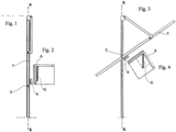
- Element G of fig. 2 is installed in such a way that when the wing 1 is closed the x axis is parallel to the vertical position of the wing.
- the signals emitted by the electronic accelerometer relative to the x axis is determined as a function of the projection that the inertial part G of fig. 3 (symbolically represented with a portion of the rod acting as a pendulum), with respect to gravity "g", effectuates on the x axis during the variation of the angular position assumed by the element G. Because element G is solidly fixed to the wing 1, each signal emitted by the electronic accelerometer corresponding to each of its angular positions precisely identifies the position assumed by the wing while it is moving.
Landscapes
- Engineering & Computer Science (AREA)
- Mechanical Engineering (AREA)
- Power-Operated Mechanisms For Wings (AREA)
- Invalid Beds And Related Equipment (AREA)
- Burglar Alarm Systems (AREA)
Claims (7)
- Schwingtor, das einen Flügel (1) und einen festen Torrahmen umfasst, wobei der Flügel mit einer Vorrichtung ausgestattet ist, die einen elektronischen Beschleunigungsmesser (A, G) zur Steuerung der Sicherheit des Flügels während seiner Bewegung umfasst, wobei das Tor eine Steuervorrichtung für eine automatisierte Bewegung des Flügels umfasst, wobei sich der Flügel in seiner Bewegung unter Verwendung von zwei Drehzapfen (2) dreht, die sich vertikal entlang einer auf die X-Achse ausgerichteten Führungsschiene des Rahmens bewegen; wobei
der elektronische Beschleunigungsmesser (A, G) fest mit dem Flügel verbunden ist und Signale für jede Stellung aussenden kann, die entlang des Weges der Bewegung des Flügels eingenommen wird, der von der anfänglichen vollständig geschlossenen Stellung des Flügels, in der der Flügel vertikal ausgerichtet ist, zur vollständig geöffneten Stellung geht, in der der Flügel horizontal ausgerichtet ist, und umgekehrt, wobei die Signale ein integraler Bestandteil der automatischen Steuerung sind, dadurch gekennzeichnet, dass die genannten Signale, die nach jedem Aufprall oder nach jeder Kollision mit dem Flügel des genannten Tores während der Bewegung abgegeben werden, als Signale für die Steuerung der Steuervorrichtung bezüglich der Kollisionen oder der Aufpralle verwendet werden, und zwar so, dass der sich bewegende Flügel sie entweder als einen senkrechten oder ebenen Kollisions- oder Aufpralltyp in Bezug auf den sich bewegenden Flügel (1) betrachtet. - Schwingtor nach Anspruch 1, dadurch gekennzeichnet, dass jedes Signal des elektronischen Beschleunigungsmessers (A, G) mit den Werten des von Motoren für die Bewegung des Flügels (1) aufgenommenen Stroms in Beziehung gesetzt werden kann.
- Schwingtor nach einem der vorstehenden Ansprüche, dadurch gekennzeichnet, dass der elektronische Beschleunigungsmesser (A, G) mit der X-Achse nicht parallel zur Stellung des Flügels angeordnet ist, sodass er das Höchstwertsignal entsprechend den vom Flügel eingenommenen Stellungen abgibt, in denen man die maximale Empfindlichkeit gegenüber den Auswirkungen der Kollision erhalten möchte.
- Schwingtor nach einem der vorstehenden Ansprüche, dadurch gekennzeichnet, dass der elektronische Beschleunigungsmesser (A, G) ein elektronischer Beschleunigungsmesser mit einem linearen gravimetrischen Trägheitssensor (G) mit mindestens einer Achse (x, y) ist, der analoge und/oder digitale Signale abgibt.
- Schwingtor nach einem der vorstehenden Ansprüche, dadurch gekennzeichnet, dass das Signal des elektronischen Beschleunigungsmessers (A, G) nach einer Kollision des Flügels (1) mit mindestens einem anderen Signal wie dem Signal für Stromaufnahme, Vibration, Geräusch usw. kombiniert und/oder verglichen werden kann.
- Schwingtor nach einem der vorstehenden Ansprüche, dadurch gekennzeichnet, dass zwei elektronische Beschleunigungsmesser (A, G) vorhanden sind, die beide an gegenüberliegenden Enden des beweglichen Flügels (1) angeordnet sind, und dass die relativen Signale kombiniert werden können, um mehr Informationen und/oder eine höhere Genauigkeit bezüglich der Identifizierung der Kollision zu erhalten.
- Schwingtor nach einem der vorstehenden Ansprüche, dadurch gekennzeichnet, dass die von dem elektronischen Beschleunigungsmesser (A, G) in Bezug auf die verschiedenen Achsen (x, y) gelieferten Signale mit der Richtung der Kollision in Bezug auf den beweglichen Flügel (1) in Beziehung stehen.
Applications Claiming Priority (1)
| Application Number | Priority Date | Filing Date | Title |
|---|---|---|---|
| IT000093A ITPD20070093A1 (it) | 2007-03-15 | 2007-03-15 | Dispositivo per il controllo della sicurezza di un serramento durante la sua movimentazione. |
Publications (3)
| Publication Number | Publication Date |
|---|---|
| EP1970516A2 EP1970516A2 (de) | 2008-09-17 |
| EP1970516A3 EP1970516A3 (de) | 2013-11-20 |
| EP1970516B1 true EP1970516B1 (de) | 2024-06-12 |
Family
ID=39493408
Family Applications (1)
| Application Number | Title | Priority Date | Filing Date |
|---|---|---|---|
| EP08004338.3A Active EP1970516B1 (de) | 2007-03-15 | 2008-03-10 | Vorrichtung zur Kontrolle der Sicherheit eines Rahmens während dessen Bewegung |
Country Status (2)
| Country | Link |
|---|---|
| EP (1) | EP1970516B1 (de) |
| IT (1) | ITPD20070093A1 (de) |
Families Citing this family (4)
| Publication number | Priority date | Publication date | Assignee | Title |
|---|---|---|---|---|
| FR2941991B1 (fr) * | 2009-02-06 | 2011-02-25 | Somfy Sas | Procede de detection de la presence d'un element entre un seuil d'une ouverture et une extremite d'un ecran domotique motorise. |
| EP2905408B1 (de) | 2014-02-05 | 2017-03-08 | BFT SpA | Verfahren zum Erfassen von Hindernissen bei einem sich horizontal bewegenden oder um eine vertikale Achse schwenkenden Flügel |
| US10774574B2 (en) | 2018-03-26 | 2020-09-15 | Honda Motor Co., Ltd. | Operation of vehicle power doors |
| US12221822B2 (en) | 2019-06-17 | 2025-02-11 | Assa Abloy Entrance Systems Ab | Door operation management system |
Family Cites Families (2)
| Publication number | Priority date | Publication date | Assignee | Title |
|---|---|---|---|---|
| US7070226B2 (en) * | 2001-04-26 | 2006-07-04 | Litens Automotive | Powered opening mechanism and control system |
| US7119681B2 (en) * | 2004-05-11 | 2006-10-10 | Honeywell International, Inc. | MEMS based garage door sensor |
-
2007
- 2007-03-15 IT IT000093A patent/ITPD20070093A1/it unknown
-
2008
- 2008-03-10 EP EP08004338.3A patent/EP1970516B1/de active Active
Also Published As
| Publication number | Publication date |
|---|---|
| EP1970516A2 (de) | 2008-09-17 |
| EP1970516A3 (de) | 2013-11-20 |
| ITPD20070093A1 (it) | 2008-09-16 |
Similar Documents
| Publication | Publication Date | Title |
|---|---|---|
| JP5519514B2 (ja) | 侵入物に対してゲートの閉じる面を安全に保つために、垂直又は水平に移動するゲートを制御する方法 | |
| EP2395274B1 (de) | Dynamisch anpassbare Sicherheitszonen | |
| RU2571654C2 (ru) | Система управления дверью с обнаружением препятствий | |
| EP1970516B1 (de) | Vorrichtung zur Kontrolle der Sicherheit eines Rahmens während dessen Bewegung | |
| JP4939755B2 (ja) | 自動車の調整機構、より詳しくは自動車ウィンドウリフタ、のための制御装置 | |
| US6970085B2 (en) | Door sensor and door equipped with such door sensor | |
| US8991103B2 (en) | Method and device for monitoring a drive unit, especially of a window lifter, comprising a rotating drive motor | |
| US7119681B2 (en) | MEMS based garage door sensor | |
| CA2416912C (en) | Vehicle closure anti-pinch assembly having a non-contact sensor | |
| US7109677B1 (en) | Motorized barrier operator system for controlling a barrier after an obstruction detection and related methods | |
| CA2655792C (en) | System and method for controlling speed of a closure member | |
| EP2663706B1 (de) | Türanordnung und Verfahren zur Bestimmung der Ursache einer Beschleunigung einer Tür | |
| WO2005110788A2 (en) | Sensor system for vehicle door | |
| US20190136603A1 (en) | System and method for automated motor actuation in response to a travel-limit displacement of a movable barrier | |
| US20180119472A1 (en) | Monitoring system | |
| CA2942419C (en) | A position monitoring device | |
| EP3923257A1 (de) | Sicherheitsvorrichtung, systeme und verfahren | |
| US9466164B2 (en) | Monitoring and control device for a door unit | |
| FI3581747T3 (fi) | Valvontalaite | |
| US20130277437A1 (en) | Spring cycle counter | |
| JP7775094B2 (ja) | 戸開閉制御装置 | |
| JP5740495B2 (ja) | 自動ドア制御システム | |
| CN113597497B (zh) | 自动门安全系统 | |
| KR20070089407A (ko) | 차량 도어 오픈 시 측면 충돌 방지 장치 | |
| KR20070045073A (ko) | 가속도 센서를 이용한 여닫이 자동문의 안전장치 |
Legal Events
| Date | Code | Title | Description |
|---|---|---|---|
| PUAI | Public reference made under article 153(3) epc to a published international application that has entered the european phase |
Free format text: ORIGINAL CODE: 0009012 |
|
| AK | Designated contracting states |
Kind code of ref document: A2 Designated state(s): AT BE BG CH CY CZ DE DK EE ES FI FR GB GR HR HU IE IS IT LI LT LU LV MC MT NL NO PL PT RO SE SI SK TR |
|
| AX | Request for extension of the european patent |
Extension state: AL BA MK RS |
|
| PUAL | Search report despatched |
Free format text: ORIGINAL CODE: 0009013 |
|
| AK | Designated contracting states |
Kind code of ref document: A3 Designated state(s): AT BE BG CH CY CZ DE DK EE ES FI FR GB GR HR HU IE IS IT LI LT LU LV MC MT NL NO PL PT RO SE SI SK TR |
|
| AX | Request for extension of the european patent |
Extension state: AL BA MK RS |
|
| RIC1 | Information provided on ipc code assigned before grant |
Ipc: E05F 15/00 20060101AFI20131011BHEP Ipc: E05F 15/20 20060101ALI20131011BHEP Ipc: E05D 15/44 20060101ALN20131011BHEP |
|
| 17P | Request for examination filed |
Effective date: 20140519 |
|
| RBV | Designated contracting states (corrected) |
Designated state(s): AT BE BG CH CY CZ DE DK EE ES FI FR GB GR HR HU IE IS IT LI LT LU LV MC MT NL NO PL PT RO SE SI SK TR |
|
| AKX | Designation fees paid |
Designated state(s): AT BE BG CH CY LI |
|
| REG | Reference to a national code |
Ref country code: DE Ref legal event code: R108 |
|
| REG | Reference to a national code |
Ref country code: DE Ref legal event code: R108 Effective date: 20140723 |
|
| RBV | Designated contracting states (corrected) |
Designated state(s): AT BE BG CH CY CZ DE DK EE ES FI FR GB GR HR HU IE IS IT LI LT LU LV MC MT NL NO PL PT RO SE SI SK TR |
|
| 17Q | First examination report despatched |
Effective date: 20160617 |
|
| STAA | Information on the status of an ep patent application or granted ep patent |
Free format text: STATUS: EXAMINATION IS IN PROGRESS |
|
| GRAP | Despatch of communication of intention to grant a patent |
Free format text: ORIGINAL CODE: EPIDOSNIGR1 |
|
| STAA | Information on the status of an ep patent application or granted ep patent |
Free format text: STATUS: GRANT OF PATENT IS INTENDED |
|
| RIC1 | Information provided on ipc code assigned before grant |
Ipc: E05D 15/44 20060101ALI20240213BHEP Ipc: E05F 15/41 20150101ALI20240213BHEP Ipc: E05F 15/40 20150101ALI20240213BHEP Ipc: E05D 15/38 20060101ALI20240213BHEP Ipc: E05F 15/00 20060101AFI20240213BHEP |
|
| INTG | Intention to grant announced |
Effective date: 20240312 |
|
| GRAS | Grant fee paid |
Free format text: ORIGINAL CODE: EPIDOSNIGR3 |
|
| GRAA | (expected) grant |
Free format text: ORIGINAL CODE: 0009210 |
|
| STAA | Information on the status of an ep patent application or granted ep patent |
Free format text: STATUS: THE PATENT HAS BEEN GRANTED |
|
| AK | Designated contracting states |
Kind code of ref document: B1 Designated state(s): AT BE BG CH CY CZ DE DK EE ES FI FR GB GR HR HU IE IS IT LI LT LU LV MC MT NL NO PL PT RO SE SI SK TR |
|
| REG | Reference to a national code |
Ref country code: GB Ref legal event code: FG4D |
|
| REG | Reference to a national code |
Ref country code: CH Ref legal event code: EP |
|
| REG | Reference to a national code |
Ref country code: IE Ref legal event code: FG4D |
|
| REG | Reference to a national code |
Ref country code: DE Ref legal event code: R096 Ref document number: 602008065047 Country of ref document: DE |
|
| PG25 | Lapsed in a contracting state [announced via postgrant information from national office to epo] |
Ref country code: BG Free format text: LAPSE BECAUSE OF FAILURE TO SUBMIT A TRANSLATION OF THE DESCRIPTION OR TO PAY THE FEE WITHIN THE PRESCRIBED TIME-LIMIT Effective date: 20240612 |
|
| PG25 | Lapsed in a contracting state [announced via postgrant information from national office to epo] |
Ref country code: FI Free format text: LAPSE BECAUSE OF FAILURE TO SUBMIT A TRANSLATION OF THE DESCRIPTION OR TO PAY THE FEE WITHIN THE PRESCRIBED TIME-LIMIT Effective date: 20240612 Ref country code: HR Free format text: LAPSE BECAUSE OF FAILURE TO SUBMIT A TRANSLATION OF THE DESCRIPTION OR TO PAY THE FEE WITHIN THE PRESCRIBED TIME-LIMIT Effective date: 20240612 |
|
| REG | Reference to a national code |
Ref country code: LT Ref legal event code: MG9D |
|
| PG25 | Lapsed in a contracting state [announced via postgrant information from national office to epo] |
Ref country code: GR Free format text: LAPSE BECAUSE OF FAILURE TO SUBMIT A TRANSLATION OF THE DESCRIPTION OR TO PAY THE FEE WITHIN THE PRESCRIBED TIME-LIMIT Effective date: 20240913 |
|
| REG | Reference to a national code |
Ref country code: NL Ref legal event code: MP Effective date: 20240612 |
|
| PG25 | Lapsed in a contracting state [announced via postgrant information from national office to epo] |
Ref country code: ES Free format text: LAPSE BECAUSE OF FAILURE TO SUBMIT A TRANSLATION OF THE DESCRIPTION OR TO PAY THE FEE WITHIN THE PRESCRIBED TIME-LIMIT Effective date: 20240612 |
|
| PG25 | Lapsed in a contracting state [announced via postgrant information from national office to epo] |
Ref country code: LV Free format text: LAPSE BECAUSE OF FAILURE TO SUBMIT A TRANSLATION OF THE DESCRIPTION OR TO PAY THE FEE WITHIN THE PRESCRIBED TIME-LIMIT Effective date: 20240612 |
|
| PG25 | Lapsed in a contracting state [announced via postgrant information from national office to epo] |
Ref country code: NO Free format text: LAPSE BECAUSE OF FAILURE TO SUBMIT A TRANSLATION OF THE DESCRIPTION OR TO PAY THE FEE WITHIN THE PRESCRIBED TIME-LIMIT Effective date: 20240912 Ref country code: LV Free format text: LAPSE BECAUSE OF FAILURE TO SUBMIT A TRANSLATION OF THE DESCRIPTION OR TO PAY THE FEE WITHIN THE PRESCRIBED TIME-LIMIT Effective date: 20240612 Ref country code: HR Free format text: LAPSE BECAUSE OF FAILURE TO SUBMIT A TRANSLATION OF THE DESCRIPTION OR TO PAY THE FEE WITHIN THE PRESCRIBED TIME-LIMIT Effective date: 20240612 Ref country code: GR Free format text: LAPSE BECAUSE OF FAILURE TO SUBMIT A TRANSLATION OF THE DESCRIPTION OR TO PAY THE FEE WITHIN THE PRESCRIBED TIME-LIMIT Effective date: 20240913 Ref country code: FI Free format text: LAPSE BECAUSE OF FAILURE TO SUBMIT A TRANSLATION OF THE DESCRIPTION OR TO PAY THE FEE WITHIN THE PRESCRIBED TIME-LIMIT Effective date: 20240612 Ref country code: ES Free format text: LAPSE BECAUSE OF FAILURE TO SUBMIT A TRANSLATION OF THE DESCRIPTION OR TO PAY THE FEE WITHIN THE PRESCRIBED TIME-LIMIT Effective date: 20240612 Ref country code: BG Free format text: LAPSE BECAUSE OF FAILURE TO SUBMIT A TRANSLATION OF THE DESCRIPTION OR TO PAY THE FEE WITHIN THE PRESCRIBED TIME-LIMIT Effective date: 20240612 |
|
| PG25 | Lapsed in a contracting state [announced via postgrant information from national office to epo] |
Ref country code: NL Free format text: LAPSE BECAUSE OF FAILURE TO SUBMIT A TRANSLATION OF THE DESCRIPTION OR TO PAY THE FEE WITHIN THE PRESCRIBED TIME-LIMIT Effective date: 20240612 |
|
| REG | Reference to a national code |
Ref country code: AT Ref legal event code: MK05 Ref document number: 1694385 Country of ref document: AT Kind code of ref document: T Effective date: 20240612 |
|
| PG25 | Lapsed in a contracting state [announced via postgrant information from national office to epo] |
Ref country code: NL Free format text: LAPSE BECAUSE OF FAILURE TO SUBMIT A TRANSLATION OF THE DESCRIPTION OR TO PAY THE FEE WITHIN THE PRESCRIBED TIME-LIMIT Effective date: 20240612 |
|
| PG25 | Lapsed in a contracting state [announced via postgrant information from national office to epo] |
Ref country code: PT Free format text: LAPSE BECAUSE OF FAILURE TO SUBMIT A TRANSLATION OF THE DESCRIPTION OR TO PAY THE FEE WITHIN THE PRESCRIBED TIME-LIMIT Effective date: 20241014 |
|
| PG25 | Lapsed in a contracting state [announced via postgrant information from national office to epo] |
Ref country code: PT Free format text: LAPSE BECAUSE OF FAILURE TO SUBMIT A TRANSLATION OF THE DESCRIPTION OR TO PAY THE FEE WITHIN THE PRESCRIBED TIME-LIMIT Effective date: 20241014 |
|
| PG25 | Lapsed in a contracting state [announced via postgrant information from national office to epo] |
Ref country code: PL Free format text: LAPSE BECAUSE OF FAILURE TO SUBMIT A TRANSLATION OF THE DESCRIPTION OR TO PAY THE FEE WITHIN THE PRESCRIBED TIME-LIMIT Effective date: 20240612 |
|
| PG25 | Lapsed in a contracting state [announced via postgrant information from national office to epo] |
Ref country code: EE Free format text: LAPSE BECAUSE OF FAILURE TO SUBMIT A TRANSLATION OF THE DESCRIPTION OR TO PAY THE FEE WITHIN THE PRESCRIBED TIME-LIMIT Effective date: 20240612 |
|
| PG25 | Lapsed in a contracting state [announced via postgrant information from national office to epo] |
Ref country code: AT Free format text: LAPSE BECAUSE OF FAILURE TO SUBMIT A TRANSLATION OF THE DESCRIPTION OR TO PAY THE FEE WITHIN THE PRESCRIBED TIME-LIMIT Effective date: 20240612 Ref country code: IS Free format text: LAPSE BECAUSE OF FAILURE TO SUBMIT A TRANSLATION OF THE DESCRIPTION OR TO PAY THE FEE WITHIN THE PRESCRIBED TIME-LIMIT Effective date: 20241012 |
|
| PG25 | Lapsed in a contracting state [announced via postgrant information from national office to epo] |
Ref country code: CZ Free format text: LAPSE BECAUSE OF FAILURE TO SUBMIT A TRANSLATION OF THE DESCRIPTION OR TO PAY THE FEE WITHIN THE PRESCRIBED TIME-LIMIT Effective date: 20240612 |
|
| PG25 | Lapsed in a contracting state [announced via postgrant information from national office to epo] |
Ref country code: RO Free format text: LAPSE BECAUSE OF FAILURE TO SUBMIT A TRANSLATION OF THE DESCRIPTION OR TO PAY THE FEE WITHIN THE PRESCRIBED TIME-LIMIT Effective date: 20240612 Ref country code: SK Free format text: LAPSE BECAUSE OF FAILURE TO SUBMIT A TRANSLATION OF THE DESCRIPTION OR TO PAY THE FEE WITHIN THE PRESCRIBED TIME-LIMIT Effective date: 20240612 |
|
| PG25 | Lapsed in a contracting state [announced via postgrant information from national office to epo] |
Ref country code: SK Free format text: LAPSE BECAUSE OF FAILURE TO SUBMIT A TRANSLATION OF THE DESCRIPTION OR TO PAY THE FEE WITHIN THE PRESCRIBED TIME-LIMIT Effective date: 20240612 Ref country code: RO Free format text: LAPSE BECAUSE OF FAILURE TO SUBMIT A TRANSLATION OF THE DESCRIPTION OR TO PAY THE FEE WITHIN THE PRESCRIBED TIME-LIMIT Effective date: 20240612 Ref country code: PL Free format text: LAPSE BECAUSE OF FAILURE TO SUBMIT A TRANSLATION OF THE DESCRIPTION OR TO PAY THE FEE WITHIN THE PRESCRIBED TIME-LIMIT Effective date: 20240612 Ref country code: IS Free format text: LAPSE BECAUSE OF FAILURE TO SUBMIT A TRANSLATION OF THE DESCRIPTION OR TO PAY THE FEE WITHIN THE PRESCRIBED TIME-LIMIT Effective date: 20241012 Ref country code: EE Free format text: LAPSE BECAUSE OF FAILURE TO SUBMIT A TRANSLATION OF THE DESCRIPTION OR TO PAY THE FEE WITHIN THE PRESCRIBED TIME-LIMIT Effective date: 20240612 Ref country code: CZ Free format text: LAPSE BECAUSE OF FAILURE TO SUBMIT A TRANSLATION OF THE DESCRIPTION OR TO PAY THE FEE WITHIN THE PRESCRIBED TIME-LIMIT Effective date: 20240612 Ref country code: AT Free format text: LAPSE BECAUSE OF FAILURE TO SUBMIT A TRANSLATION OF THE DESCRIPTION OR TO PAY THE FEE WITHIN THE PRESCRIBED TIME-LIMIT Effective date: 20240612 |
|
| REG | Reference to a national code |
Ref country code: DE Ref legal event code: R097 Ref document number: 602008065047 Country of ref document: DE |
|
| PG25 | Lapsed in a contracting state [announced via postgrant information from national office to epo] |
Ref country code: DK Free format text: LAPSE BECAUSE OF FAILURE TO SUBMIT A TRANSLATION OF THE DESCRIPTION OR TO PAY THE FEE WITHIN THE PRESCRIBED TIME-LIMIT Effective date: 20240612 |
|
| PLBE | No opposition filed within time limit |
Free format text: ORIGINAL CODE: 0009261 |
|
| STAA | Information on the status of an ep patent application or granted ep patent |
Free format text: STATUS: NO OPPOSITION FILED WITHIN TIME LIMIT |
|
| 26N | No opposition filed |
Effective date: 20250313 |
|
| PG25 | Lapsed in a contracting state [announced via postgrant information from national office to epo] |
Ref country code: SE Free format text: LAPSE BECAUSE OF FAILURE TO SUBMIT A TRANSLATION OF THE DESCRIPTION OR TO PAY THE FEE WITHIN THE PRESCRIBED TIME-LIMIT Effective date: 20240612 |
|
| REG | Reference to a national code |
Ref country code: DE Ref legal event code: R119 Ref document number: 602008065047 Country of ref document: DE |
|
| PG25 | Lapsed in a contracting state [announced via postgrant information from national office to epo] |
Ref country code: MC Free format text: LAPSE BECAUSE OF FAILURE TO SUBMIT A TRANSLATION OF THE DESCRIPTION OR TO PAY THE FEE WITHIN THE PRESCRIBED TIME-LIMIT Effective date: 20240612 |
|
| REG | Reference to a national code |
Ref country code: CH Ref legal event code: H13 Free format text: ST27 STATUS EVENT CODE: U-0-0-H10-H13 (AS PROVIDED BY THE NATIONAL OFFICE) Effective date: 20251023 |
|
| PG25 | Lapsed in a contracting state [announced via postgrant information from national office to epo] |
Ref country code: LU Free format text: LAPSE BECAUSE OF NON-PAYMENT OF DUE FEES Effective date: 20250310 |
|
| GBPC | Gb: european patent ceased through non-payment of renewal fee |
Effective date: 20250310 |
|
| REG | Reference to a national code |
Ref country code: BE Ref legal event code: MM Effective date: 20250331 |
|
| PG25 | Lapsed in a contracting state [announced via postgrant information from national office to epo] |
Ref country code: DE Free format text: LAPSE BECAUSE OF NON-PAYMENT OF DUE FEES Effective date: 20251001 |
|
| PG25 | Lapsed in a contracting state [announced via postgrant information from national office to epo] |
Ref country code: GB Free format text: LAPSE BECAUSE OF NON-PAYMENT OF DUE FEES Effective date: 20250310 |
|
| PG25 | Lapsed in a contracting state [announced via postgrant information from national office to epo] |
Ref country code: FR Free format text: LAPSE BECAUSE OF NON-PAYMENT OF DUE FEES Effective date: 20250331 |
|
| PG25 | Lapsed in a contracting state [announced via postgrant information from national office to epo] |
Ref country code: BE Free format text: LAPSE BECAUSE OF NON-PAYMENT OF DUE FEES Effective date: 20250331 |
|
| PG25 | Lapsed in a contracting state [announced via postgrant information from national office to epo] |
Ref country code: CH Free format text: LAPSE BECAUSE OF NON-PAYMENT OF DUE FEES Effective date: 20250331 |
|
| PG25 | Lapsed in a contracting state [announced via postgrant information from national office to epo] |
Ref country code: IE Free format text: LAPSE BECAUSE OF NON-PAYMENT OF DUE FEES Effective date: 20250310 |
|
| PGFP | Annual fee paid to national office [announced via postgrant information from national office to epo] |
Ref country code: IT Payment date: 20260227 Year of fee payment: 19 |