EP1970234A2 - Sun roller blind for motor vehicles - Google Patents
Sun roller blind for motor vehicles Download PDFInfo
- Publication number
- EP1970234A2 EP1970234A2 EP08003631A EP08003631A EP1970234A2 EP 1970234 A2 EP1970234 A2 EP 1970234A2 EP 08003631 A EP08003631 A EP 08003631A EP 08003631 A EP08003631 A EP 08003631A EP 1970234 A2 EP1970234 A2 EP 1970234A2
- Authority
- EP
- European Patent Office
- Prior art keywords
- shaft
- roller blind
- motor
- blind
- winding shaft
- Prior art date
- Legal status (The legal status is an assumption and is not a legal conclusion. Google has not performed a legal analysis and makes no representation as to the accuracy of the status listed.)
- Pending
Links
Images

Classifications
-
- B—PERFORMING OPERATIONS; TRANSPORTING
- B60—VEHICLES IN GENERAL
- B60J—WINDOWS, WINDSCREENS, NON-FIXED ROOFS, DOORS, OR SIMILAR DEVICES FOR VEHICLES; REMOVABLE EXTERNAL PROTECTIVE COVERINGS SPECIALLY ADAPTED FOR VEHICLES
- B60J3/00—Antiglare equipment associated with windows or windscreens; Sun visors for vehicles
- B60J3/02—Antiglare equipment associated with windows or windscreens; Sun visors for vehicles adjustable in position
-
- B—PERFORMING OPERATIONS; TRANSPORTING
- B60—VEHICLES IN GENERAL
- B60J—WINDOWS, WINDSCREENS, NON-FIXED ROOFS, DOORS, OR SIMILAR DEVICES FOR VEHICLES; REMOVABLE EXTERNAL PROTECTIVE COVERINGS SPECIALLY ADAPTED FOR VEHICLES
- B60J1/00—Windows; Windscreens; Accessories therefor
- B60J1/20—Accessories, e.g. wind deflectors, blinds
- B60J1/2011—Blinds; curtains or screens reducing heat or light intensity
- B60J1/2013—Roller blinds
- B60J1/2019—Roller blinds powered, e.g. by electric, hydraulic or pneumatic actuators
- B60J1/2025—Roller blinds powered, e.g. by electric, hydraulic or pneumatic actuators with flexible actuating elements connected to the draw bar for pulling only, e.g. cords, wires or cables
-
- B—PERFORMING OPERATIONS; TRANSPORTING
- B60—VEHICLES IN GENERAL
- B60J—WINDOWS, WINDSCREENS, NON-FIXED ROOFS, DOORS, OR SIMILAR DEVICES FOR VEHICLES; REMOVABLE EXTERNAL PROTECTIVE COVERINGS SPECIALLY ADAPTED FOR VEHICLES
- B60J1/00—Windows; Windscreens; Accessories therefor
- B60J1/20—Accessories, e.g. wind deflectors, blinds
- B60J1/2011—Blinds; curtains or screens reducing heat or light intensity
- B60J1/2013—Roller blinds
- B60J1/2066—Arrangement of blinds in vehicles
- B60J1/2072—Blinds with inclined or vertical orientation of the winding axis
-
- B—PERFORMING OPERATIONS; TRANSPORTING
- B60—VEHICLES IN GENERAL
- B60J—WINDOWS, WINDSCREENS, NON-FIXED ROOFS, DOORS, OR SIMILAR DEVICES FOR VEHICLES; REMOVABLE EXTERNAL PROTECTIVE COVERINGS SPECIALLY ADAPTED FOR VEHICLES
- B60J1/00—Windows; Windscreens; Accessories therefor
- B60J1/20—Accessories, e.g. wind deflectors, blinds
- B60J1/2011—Blinds; curtains or screens reducing heat or light intensity
- B60J1/2013—Roller blinds
- B60J1/2066—Arrangement of blinds in vehicles
- B60J1/2086—Arrangement of blinds in vehicles specially adapted for openable windows, e.g. side window
Definitions
- the invention relates to a sun blind for a window opening of a motor vehicle.
- the sunshade is designed, for example, as a side window blind for a side window, as a rear window blind for a rear window and / or as a panorama window blind for a panoramic window in a vehicle roof.
- any type of roller blind is designated as a sun protection blind, by which the penetration of sunlight is prevented and / or the window opening is darkened or at least covered.
- the sunscreen can also serve as a screen.
- a roller blind is usually a knitted fabric. However, it is also possible to use fabrics and / or plastic films or the like as a roller blind.
- the winding spool arrangement comprises a winding spool which can be rotated relative to the winding shaft, wherein a torsion spring is arranged between the winding spool arrangement and the winding shaft, which is biased against each other by a relative rotation of the winding spool arrangement and the winding shaft in the sense of tensioning the composite system.
- a winding and / or unwinding of the roller blind is effected by a movement of a Switzerlandspriegels, which connects a free end of the roller blind with the tension cables.
- a so-called spring motor is provided for winding and tensioning the roller blind.
- a so-called spring motor is provided for winding and tensioning the roller blind.
- it is off EP 1 123 824 A2 a trained as a side window blind sunblind for a side window opening of a motor vehicle, which is a winding shaft, a roller blind, which is fixed with a first edge on the winding shaft, a pull-out profile, which is operatively connected to one of the first edge opposite second edge of the blind so that by means the pull-out profile, the roller blind from the winding shaft is removable, and a drive device comprises a spring motor, wherein the spring motor has a spring element, the roller blind is deducted against a restoring force of the spring element of the winding shaft and the roller blind can be wound by the restoring force of the spring element.
- a necessary restoring force and thus a size of a spring element to be used depends inter alia on a maximum extension length the roller blind from.
- pulling out a sun blind against a high restoring force compromise a comfort of a manual extension and / or require a stronger drive motor for an automated drive, which in turn has an increased space requirement as a result.
- usually only a small installation space is available for attaching a side window roller blind.
- a roller blind for a window opening of a motor vehicle which has a winding roller, a roller blind, which is fastened with a first edge on the winding shaft, a pull-out profile which is operatively connected to a second edge of the roller blind opposite the first edge, so that by means of the pull-out profile, the roller blind from the winding shaft is removable, and a drive device comprising a spring motor having a spring motor, wherein the spring motor comprises a shaft rotatably mounted relative to the winding shaft, the spring element between the shaft of the spring motor and the winding shaft is arranged and a rotational movement the shaft is synchronized with a displacement of the pull-out profile when removing and / or winding up the roller blind.
- the shaft of the spring motor of the winding shaft can precede due to the rotational speed of the winding shaft decreasing with increasing winding diameter of the roller blind on the winding shaft.
- the spring element is tensioned so that a necessary force is applied to wind up the roller blind.
- the drive device comprises an electric motor, in particular a geared motor.
- a remote-controlled drive for example, by a driver and / or a user in a simple manner possible.
- a displacement of the extension profile can be done manually, pneumatically and / or hydraulically, with suitable coupling means are provided to synchronize a movement of the pull-out profile with the rotational movement of the shaft of the spring motor.
- a belt drive may be designed, for example, as a toothed belt drive, wherein the belt drive is driven by means of a gear.
- the rope and / or belt drive comprises an endless rope or an endless belt.
- the extension profile is attached in one embodiment at a suitable position on the endless rope or the endless belt.
- the belt and / or the rope continues to drive the shaft of the spring motor via a frictional force and / or a positive connection, for example via a toothed belt.
- a drive shaft of the electric motor is arranged parallel to the shaft of the spring motor, wherein the distance between the drive shaft and the shaft of the spring motor is greater than or equal to a maximum extension length.
- the shaft of the spring motor also serves as a reverse role for the rope or belt drive.
- the shaft may have a suitable diameter for the movement and / or be designed for a movement entry with a flange or the like.
- the drive device comprises at least one deflection roller. This makes it possible to arrange the drive motor at a suitable position in the motor vehicle.
- the drive device comprises a pressure-resistant, flexible, elongate element and / or a toothed rack, wherein the pull-out profile and the shaft are drivable by means of the pressure-resistant, flexible element and / or the rack.
- the pressure-resistant, flexible element is, for example, a flexible plastic and / or metal wire, a core of a Bowden cable, a stranded wire strand or a toothed cord. The flexible element is stowed to save space within the vehicle door, for example, rollable on a shaft.
- a toothed cord is referred to a flexible force transmission means in the context of the invention, which is very elongated in relation to its thickness and through which both tensile and compressive forces are transferable.
- a toothed cord includes, for example, a flexurally elastic core, which is usually cylindrical in shape, and a helix wound around the core so as to form a helical toothing.
- the toothed cord has sufficient rigidity to the pull-out profile to move the sun blind, especially when the toothed cord is guided in a guide.
- the drive shaft is arranged coaxially to the shaft of the spring motor.
- the shaft can be driven directly via the drive motor.
- a motion is transmitted to the extension profile, for example by means of a cable and / or belt drive and / or by means of a rack or the like.
- the sunshade is designed as a side window blind, wherein the winding shaft is arranged parallel to a lateral edge of a window opening.
- the winding shaft is usually only little space in the axial direction of the winding shaft available.
- the inventive rotatable mounting of the spring motor can be dispensed with a large return spring, so that a space requirement is significantly reduced.
- the blank of the roller blind corresponds at least approximately to a shape of a window opening of a side window. This makes it possible to achieve a good darkening and / or good sun protection.
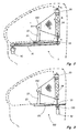
- FIG. 1 schematically shows a rear right side door 1 of a motor vehicle, on which a sunshade invention, which is designed as a side window roller blind 2, is arranged.
- the side door 1 has a window opening 10, which can be covered by the side window roller blind 2.
- the window opening 10 has a front edge 11, wherein a winding shaft 20 of the illustrated side window roller blind 2 is arranged parallel to the edge 11 of the side window opening 10.
- the side window roller blind 2 comprises a roller blind 21, which is attached to the winding shaft 20 with a non-visible, first edge.
- the roller blind 21 is for example a woven fabric, knitted fabric, a plastic film or the like, which is made opaque to visible light and / or ultraviolet light.
- the side window roller blind 2 further comprises a pull-out profile 22, which is operatively connected to a second edge 210 of the roller blind 21 opposite the first edge, so that the roller blind 21 can be pulled off the winding shaft 20 by means of the pull-out profile 22.
- a drive device 3 of the side window roller blind 2 has a spring motor with a arranged in the winding shaft 20, in FIG. 1 invisible spring element on.
- the roller blind 21 is contrary to a restoring force of the spring element, not shown, of the winding shaft 20 by moving the extension profile 22 in an extension direction A unwound. A winding of the roller blind 21 on the winding shaft 20 by means of a restoring force of the spring element.
- a displacement of the extension profile 22 takes place in the in FIG. 1 illustrated, the first embodiment by means of a belt drive comprising an endless belt 31.
- the endless belt 31 is driven by an electric geared motor 32.
- the pull-out profile 22 is attached, for example glued to it and / or riveted.
- the spring motor 30 has a shaft 33 rotatably mounted relative to the winding shaft 20, wherein the shaft 33 is likewise driven by the endless belt 31, so that a rotational movement of the shaft 33 is synchronized with a translational movement of the extension profile 22.
- FIG. 2 schematically shows the side window blind 2 according to FIG. 1 in a partially cutaway view, with a better understanding of a contour of the side door 1 according to FIG. 1 is shown in dashed lines.
- the winding shaft 20 is shown cut free, so that a spring element 34 of the spring motor is visible.
- the spring element 34 is disposed between the winding shaft 20 and the shaft 33 of the spring motor 30, wherein, for example, the ends of the spring element 34 are connected to the shaft 33 and the winding shaft 20 for a movement transmission.
- the movement of the belt 31 is transmitted to the shaft 33, so that the shaft 33 rotates at a rotational speed ⁇ 1 .
- the winding shaft 20 Due to a displacement of the pull-out profile 22 at a speed v, the winding shaft 20 is driven to unroll the roller blind web 21 at a rotational speed ⁇ 2 .
- a winding diameter of the roller blind 21 on the winding shaft 20 decreases.
- the rotational speed of the winding shaft 20 increases during removal. If the rotational speed ⁇ 2 of the winding shaft 20 exceeds a rotational speed ⁇ 1 of the shaft 33, the spring element 34 is tensioned.
- the illustrated pull-out profile 22 has a gallows shape, wherein the pull-out profile 22 is attached via a carriage 23 to the belt 31.
- the carriage 23 can be mounted displaceably in a guide, not shown.
- FIG. 3 shows a second embodiment of a sunshade 102 according to the invention.
- the sunshade 102 substantially corresponds to the sunshade 2 according to FIG. 2 and for the same components, the same reference numerals are used. On a detailed Description of these components is omitted.
- a drive motor 32 is disposed coaxially with the shaft 33 of the spring motor 30.
- a drive shaft of the drive motor 32 can be designed in one piece with the shaft 33.
- a gear 130 is arranged, through which a rack 131 is driven.
- the rack 131 is operatively connected to the pull-out profile 22, so that the pull-out profile 22 is displaceable by means of the rack 131.
- the rack 131 and / or the carriage 23 can be displaceably mounted in a guide, not shown, and thus guided.
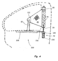
- FIG. 4 shows a side window roller blind 202 according to a third embodiment of the invention.
- the side window shade 202 substantially corresponds to the side window shade 102 according to FIG. 3 and for the same components, the same reference numerals are used. On a description of these components is omitted.
- the toothed cord 231 is in the illustrated embodiment on a coaxial with the drive motor 32 arranged shaft 232 wound up.
- the toothed cord 231 and the slide 23 are slidably mounted in a guide 235, so as to prevent buckling of the toothed cord 231.
- an inventive sunshade can also be arranged on a panoramic window and / or a rear window of a motor vehicle.
Abstract
Description
Die Erfindung betrifft ein Sonnenschutzrollo für eine Fensteröffnung eines Kraftfahrzeugs.The invention relates to a sun blind for a window opening of a motor vehicle.
Das Sonnenschutzrollo ist beispielsweise als Seitenfensterrollo für ein Seitenfenster, als Heckfensterrollo für ein Heckfenster und/oder als Panoramafensterrollo für ein Panoramafenster in einem Fahrzeughimmel ausgebildet. Als Sonnenschutzrollo wird dabei jegliche Art von Rollo bezeichnet, durch welche ein Eintreten von Sonnenlicht verhindert und/oder die Fensteröffnung verdunkelt oder zumindest abgedeckt wird. Das Sonnenschutzrollo kann dabei auch als Sichtschutz dienen. Eine Rollobahn ist üblicherweise ein Gewirke. Es können jedoch auch Gewebe und/oder Kunststofffolien oder dergleichen als Rollobahn eingesetzt werden.The sunshade is designed, for example, as a side window blind for a side window, as a rear window blind for a rear window and / or as a panorama window blind for a panoramic window in a vehicle roof. In this case, any type of roller blind is designated as a sun protection blind, by which the penetration of sunlight is prevented and / or the window opening is darkened or at least covered. The sunscreen can also serve as a screen. A roller blind is usually a knitted fabric. However, it is also possible to use fabrics and / or plastic films or the like as a roller blind.
Aus der
In anderen Rolloanordnungen ist ein sogenannter Federmotor zum Aufwickeln und Spannen der Rollobahn vorgesehen. Beispielsweise ist aus
Eine notwendige Rückstellkraft und damit eine Größe eines einzusetzenden Federelements hängt unter anderem von einer maximalen Auszugslänge der Rollobahn ab. Je größer die notwendige Rückstellkraft, desto größer ist somit auch ein notwendiger Bauraum für das Sonnenschutzrollo. Zudem kann ein Ausziehen eines Sonnenschutzrollos gegen eine hohe Rückstellkraft einen Komfort eines manuellen Auszugs beeinträchtigen und/oder einen stärkeren Antriebsmotor für einen automatisierten Antrieb erfordern, was wiederum einen Vergrößerten Bauraumbedarf als Folge hat. Insbesondere im Bereich eines Seitenfensters steht jedoch üblicherweise nur ein geringer Bauraum zur Anbringung eines Seitenfensterrollos zur Verfügung.A necessary restoring force and thus a size of a spring element to be used depends inter alia on a maximum extension length the roller blind from. The greater the necessary restoring force, the greater the necessary space for the sunblind. In addition, pulling out a sun blind against a high restoring force compromise a comfort of a manual extension and / or require a stronger drive motor for an automated drive, which in turn has an increased space requirement as a result. However, in particular in the area of a side window, usually only a small installation space is available for attaching a side window roller blind.
Es ist daher Aufgabe der Erfindung, ein besonders kleinbauendes Sonnenschutzrollo, insbesondere zur Abdeckung einer Seitenfensteröffnung zu schaffen.It is therefore an object of the invention to provide a particularly small-sized sunshade, in particular to cover a side window opening.
Diese Aufgabe wird durch ein Sonnenschutzrollo für eine Fensteröffnung eines Kraftfahrzeugs gelöst, das eine Wickelwelle, eine Rollobahn, welche mit einer ersten Kante an der Wickelwelle befestigt ist, ein Auszugsprofil, welches mit einer der ersten Kante gegenüberliegenden zweiten Kante der Rollobahn wirkverbunden ist, so dass mittels des Auszugsprofils die Rollobahn von der Wickelwelle abziehbar ist, und eine Antriebsvorrichtung mit einem ein Federelement aufweisenden Federmotor umfasst, wobei der Federmotor eine relativ zu der Wickelwelle verdrehbar gelagerte Welle umfasst, das Federelement zwischen der Welle des Federmotors und der Wickelwelle angeordnet ist und eine Drehbewegung der Welle mit einer Verschiebung des Auszugsprofils beim Abziehen und/oder Aufwickeln der Rollobahn synchronisiert ist.This object is achieved by a roller blind for a window opening of a motor vehicle, which has a winding roller, a roller blind, which is fastened with a first edge on the winding shaft, a pull-out profile which is operatively connected to a second edge of the roller blind opposite the first edge, so that by means of the pull-out profile, the roller blind from the winding shaft is removable, and a drive device comprising a spring motor having a spring motor, wherein the spring motor comprises a shaft rotatably mounted relative to the winding shaft, the spring element between the shaft of the spring motor and the winding shaft is arranged and a rotational movement the shaft is synchronized with a displacement of the pull-out profile when removing and / or winding up the roller blind.
Durch ein synchronisiertes Mitdrehen der Welle ist es möglich, ein Federelement mit einer geringeren Rückstellkraft vorzusehen, als bei einem gleich dimensionierten Rollo mit unbewegter Welle. Wird das Auszugsprofil mit einer konstanten Geschwindigkeit zum Abrollen der Rollobahn bewegt, so dreht auch die Welle des Federmotors mit einer konstanten Geschwindigkeit. Die Drehgeschwindigkeit der Wickelwelle steigt dagegen aufgrund des abnehmenden Wickeldurchmessers der Rollobahn an der Wickelwelle beim Abwickeln der Rollobahn. Durch das Federelement bleibt eine ausreichende Spannung in der Rollobahn vorhanden, wobei jedoch aufgrund der Verdrehung der Welle des Federmotors verhindert wird, dass Gegenkräfte zum Abwickeln zu groß werden. Bei Aufwickeln der Rollobahn auf die Wickelwelle kann aufgrund der mit steigendem Wickeldurchmesser der Rollobahn an der Wickelwelle sinkenden Drehgeschwindigkeit der Wickelwelle die Welle des Federmotors der Wickelwelle vorauseilen. Dadurch wird das Federelement so gespannt, dass eine notwendige Kraft zum Aufwickeln der Rollobahn aufgebracht wird.By synchronized co-rotation of the shaft, it is possible to provide a spring element with a lower restoring force, as in a same sized blind with stationary shaft. If the pull-out profile is moved at a constant speed to unwind the roller blind, the shaft of the spring motor also rotates at a constant speed Speed. In contrast, the rotational speed of the winding shaft increases due to the decreasing winding diameter of the roller blind on the winding shaft during unwinding of the roller blind. Due to the spring element, sufficient tension remains in the roller blind, but due to the rotation of the shaft of the spring motor, it is prevented that counter-forces for unwinding become too great. When the roller blind is wound onto the winding shaft, the shaft of the spring motor of the winding shaft can precede due to the rotational speed of the winding shaft decreasing with increasing winding diameter of the roller blind on the winding shaft. As a result, the spring element is tensioned so that a necessary force is applied to wind up the roller blind.
In einer Ausgestaltung der Erfindung umfasst die Antriebsvorrichtung einen Elektromotor, insbesondere einen Getriebemotor. Durch einen derartigen Motor ist ein ferngesteuerter Antrieb, beispielsweise durch einen Fahrer und/oder einen Nutzer auf einfache Weise möglich. In anderen Ausgestaltungen kann ein Verschieben des Auszugsprofils manuell, pneumatisch und/oder hydraulisch erfolgen, wobei geeignete Kopplungsmittel vorgesehen sind, um eine Bewegung des Auszugsprofils mit der Drehbewegung der Welle des Federmotors zu synchronisieren.In one embodiment of the invention, the drive device comprises an electric motor, in particular a geared motor. By such a motor, a remote-controlled drive, for example, by a driver and / or a user in a simple manner possible. In other embodiments, a displacement of the extension profile can be done manually, pneumatically and / or hydraulically, with suitable coupling means are provided to synchronize a movement of the pull-out profile with the rotational movement of the shaft of the spring motor.
In einer Weiterbildung der Erfindung erfolgt eine Synchronisation mittels Seil- und/oder Riemenantrieb. Ein Riemenantrieb kann beispielsweise als Zahnriemenantrieb gestaltet sein, wobei der Riemenantrieb mittels eines Zahnrads angetrieben wird.In a further development of the invention, synchronization takes place by means of cable and / or belt drive. A belt drive may be designed, for example, as a toothed belt drive, wherein the belt drive is driven by means of a gear.
In einer Weiterbildung der Erfindung umfasst der Seil- und/oder Riemenantrieb ein Endlosseil bzw. einen Endlosriemen. Das Auszugsprofil ist in einer Ausgestaltung an einer geeigneten Position an dem Endlosseil bzw. dem Endlosriemen angebracht. Der Riemen und/oder das Seil treibt weiter die Welle des Federmotors über eine Reibkraft und/oder über einen Formschluss, beispielsweise über einen Zahnriemen.In a development of the invention, the rope and / or belt drive comprises an endless rope or an endless belt. The extension profile is attached in one embodiment at a suitable position on the endless rope or the endless belt. The belt and / or the rope continues to drive the shaft of the spring motor via a frictional force and / or a positive connection, for example via a toothed belt.
In einer Ausgestaltung der Erfindung ist eine Antriebswelle des Elektromotors parallel zu der Welle des Federmotors angeordnet, wobei der Abstand zwischen der Antriebswelle und der Welle des Federmotors größer oder gleich einer maximalen Auszugslänge ist. Bei einem Endlosriemen oder einem Endlosseil dient die Welle des Federmotors dabei auch als Umkehrrolle für den Seil- oder Riemenantrieb. Die Welle kann einen für die Bewegung geeigneten Durchmesser aufweisen und/oder für einen Bewegungseintrag mit einem Flansch oder dergleichen gestaltet sein.In one embodiment of the invention, a drive shaft of the electric motor is arranged parallel to the shaft of the spring motor, wherein the distance between the drive shaft and the shaft of the spring motor is greater than or equal to a maximum extension length. In an endless belt or an endless rope, the shaft of the spring motor also serves as a reverse role for the rope or belt drive. The shaft may have a suitable diameter for the movement and / or be designed for a movement entry with a flange or the like.
In einer weiteren Ausgestaltung umfasst die Antriebsvorrichtung mindestens eine Umlenkrolle. Dadurch ist es möglich, den Antriebsmotor an einer geeigneten Position in dem Kraftfahrzeug anzuordnen.In a further embodiment, the drive device comprises at least one deflection roller. This makes it possible to arrange the drive motor at a suitable position in the motor vehicle.
In einer weiteren Ausgestaltung umfasst die Antriebsvorrichtung ein drucksteifes, flexibles, längliches Element und/oder eine Zahnstange, wobei das Auszugsprofil und die Welle mittels des drucksteifen, flexiblen Elements und/oder der Zahnstange antreibbar sind. Das drucksteife, flexible Element ist beispielsweise ein flexibler Kunststoff- und/oder Metalldraht, eine Seele eines Bowdenzugs, eine verseilte Drahtlitze oder eine Zahnschnur. Das flexible Element ist innerhalb der Fahrzeugtür platzsparend verstaubar, beispielsweise auf einer Welle aufrollbar. Als Zahnschnur wird im Sinne der Erfindung ein flexibles Kraftübertragungsmittel bezeichnet, das im Verhältnis zu seiner Dicke sehr langgestreckt ist und durch das sowohl Zug- als auch Druckkräfte übertragbar sind. Eine Zahnschnur umfasst beispielsweise eine biegeelastische Seele, welche üblicherweise zylindrisch gestaltet ist, und einen Wendel, welcher um die Seele gewunden ist, um so eine Schrägverzahnung zu bilden. Die Zahnschnur weist eine ausreichende Steifigkeit auf, um das Auszugsprofil des Sonnenschutzrollos zu verschieben, insbesondere wenn die Zahnschnur in einer Führung geführt ist.In a further embodiment, the drive device comprises a pressure-resistant, flexible, elongate element and / or a toothed rack, wherein the pull-out profile and the shaft are drivable by means of the pressure-resistant, flexible element and / or the rack. The pressure-resistant, flexible element is, for example, a flexible plastic and / or metal wire, a core of a Bowden cable, a stranded wire strand or a toothed cord. The flexible element is stowed to save space within the vehicle door, for example, rollable on a shaft. As a toothed cord is referred to a flexible force transmission means in the context of the invention, which is very elongated in relation to its thickness and through which both tensile and compressive forces are transferable. A toothed cord includes, for example, a flexurally elastic core, which is usually cylindrical in shape, and a helix wound around the core so as to form a helical toothing. The toothed cord has sufficient rigidity to the pull-out profile to move the sun blind, especially when the toothed cord is guided in a guide.
In einer weiteren Ausgestaltung der Erfindung ist die Antriebswelle koaxial zu der Welle des Federmotors angeordnet. Die Welle ist dabei direkt über den Antriebsmotor antreibbar. Eine Bewegungsübertragung auf das Auszugsprofil erfolgt beispielsweise mittels eines Seil- und/oder Riemenantriebs und/oder mittels einer Zahnstange oder dergleichen.In a further embodiment of the invention, the drive shaft is arranged coaxially to the shaft of the spring motor. The shaft can be driven directly via the drive motor. A motion is transmitted to the extension profile, for example by means of a cable and / or belt drive and / or by means of a rack or the like.
In einer weiteren Ausgestaltung der Erfindung ist das Sonnenschutzrollo als Seitenfensterrollo ausgebildet, wobei die Wickelwelle parallel zu einem seitlichen Rand einer Fensteröffnung angeordnet ist. Insbesondere bei einer horizontal angeordneten Wickelwelle steht üblicherweise nur wenig Bauraum in Axialrichtung der Wickelwelle zur Verfügung. Durch die erfindungsgemäße drehbare Lagerung des Federmotors kann auf eine große Rückstellfeder verzichtet werden, so dass ein Platzbedarf deutlich reduziert ist.In a further embodiment of the invention, the sunshade is designed as a side window blind, wherein the winding shaft is arranged parallel to a lateral edge of a window opening. In particular, in a horizontally arranged winding shaft is usually only little space in the axial direction of the winding shaft available. The inventive rotatable mounting of the spring motor can be dispensed with a large return spring, so that a space requirement is significantly reduced.
In einer weiteren Ausgestaltung der Erfindung entspricht der Zuschnitt der Rollobahn zumindest annähernd einer Form einer Fensteröffnung eines Seitenfensters. Dadurch ist es möglich, eine gute Abdunklung und/oder einen guten Sonnenschutz zu erzielen.In a further embodiment of the invention, the blank of the roller blind corresponds at least approximately to a shape of a window opening of a side window. This makes it possible to achieve a good darkening and / or good sun protection.
Weitere Vorteile der Erfindung ergeben sich aus der nachfolgenden Beschreibung von Ausführungsbeispielen der Erfindung, die in den Zeichnungen schematisch dargestellt sind. Für gleiche oder ähnliche Bauteile werden in den Zeichnungen einheitliche Bezugszeichen verwendet. Sämtliche aus den Ansprüchen, der Beschreibung oder den Zeichnungen hervorgehende Merkmale und/oder Vorteile, einschließlich Verfahrensschritte, konstruktive Einzelheiten und räumliche Anordnungen, können sowohl für sich als auch in den verschiedensten Kombinationen erfindungswesentlich sein. Als Teil eines Ausführungsbeispiels beschriebene oder dargestellte Merkmale können ebenso in einem anderen Ausführungsbeispiel verwendet werden, um eine weitere Ausführungsform der Erfindung zu erhalten.Further advantages of the invention will become apparent from the following description of embodiments of the invention, which are shown schematically in the drawings. For identical or similar components, the same reference numbers are used in the drawings. Any features and / or advantages resulting from the claims, the description or the drawings, including method steps, constructive details and spatial arrangements, can be used both individually and in various combinations be essential to the invention. Features described or illustrated as part of one embodiment may also be used in another embodiment to obtain a further embodiment of the invention.
In den Zeichnungen zeigen:
- Fig. 1:
- eine hintere, rechte Seitentür eines Kraftfahrzeugs mit einem erfindungsgemäßen Seitenfensterrollo in einer teilweise freigeschnittenen Darstellung;
- Fig. 2:
- ein Seitenfensterrollo gemäß
Fig. 1 in einer teilweise freigeschnittenen Darstellung; - Fig. 3:
- ein zweites Ausführungsbeispiel eines erfindungsgemäßen Seitenfensterrollos in einer teilweise freigeschnittenen Darstellung und
- Fig. 4:
- ein drittes Ausführungsbeispiel eines erfindungsgemäßen Seitenfensterrollos in einer teilweise freigeschnittenen Darstellung.
- Fig. 1:
- a rear, right side door of a motor vehicle with a side window blind according to the invention in a partially cutaway representation;
- Fig. 2:
- a side window blind according to
Fig. 1 in a partially cut-away representation; - 3:
- A second embodiment of a side window blinds according to the invention in a partially cutaway representation and
- 4:
- a third embodiment of a side window blinds according to the invention in a partially cutaway representation.
Das Seitenfensterrollo 2 umfasst eine Rollobahn 21, welche mit einer nicht sichtbaren, ersten Kante an der Wickelwelle 20 befestigt ist. Die Rollobahn 21 ist beispielsweise ein Gewebe, Gewirke, eine Kunststofffolie oder dergleichen, welche für sichtbares Licht und/oder UV-Licht undurchlässig gestaltet ist.
Das Seitenfensterrollo 2 umfasst weiter ein Auszugsprofil 22, welches mit einer der ersten Kante gegenüberliegenden, zweiten Kante 210 der Rollobahn 21 wirkverbunden ist, sodass die Rollobahn 21 mittels des Auszugsprofils 22 von der Wickelwelle 20 abziehbar ist. Eine Antriebsvorrichtung 3 des Seitenfensterrollos 2 weist einen Federmotor mit einem in der Wickelwelle 20 angeordneten, in
The side
Ein Verschieben des Auszugsprofils 22 erfolgt in dem in
Erfindungsgemäß weist der Federmotor 30 eine relativ zu der Wickelwelle 20 verdrehbar gelagerte Welle 33 auf, wobei die Welle 33 ebenfalls durch den Endlosriemen 31 angetrieben wird, sodass eine Drehbewegung der Welle 33 mit einer translatorischen Bewegung des Auszugsprofils 22 synchronisiert ist.According to the invention, the spring motor 30 has a
Für die dargestellten Seitenfensterrollos mit horizontal angeordneten Wickelwellen ist eine erfindungsgemäße kleinbauende Gestaltung besonders vorteilhaft. Ein erfindungsgemäßes Sonnenschutzrollo kann jedoch auch an einem Panoramafenster und/oder einem Heckfenster eines Kraftfahrzeugs angeordnet sein.For the illustrated side window roller blinds with horizontally arranged winding shafts, a small-sized design according to the invention is particularly advantageous. However, an inventive sunshade can also be arranged on a panoramic window and / or a rear window of a motor vehicle.
Claims (10)
der Federmotor eine relativ zu der Wickelwelle (20) verdrehbar gelagerte Welle (33) aufweist, wobei das Federelement (34) zwischen der Welle (33) und der Wickelwelle (20) angeordnet ist, und eine Drehbewegung der Welle (33) mit einer Verschiebung des Auszugsprofils (22) beim Abziehen und/oder Aufwickeln der Rollobahn (21) synchronisiert ist.Sun blind for a window opening of a motor vehicle, in particular side window roller blind (2, 102, 202, 302), comprising a winding shaft (20), a roller blind (21) which is fastened with a first edge to the winding shaft (20), a pull-out profile (22 ), which is operatively connected to one of the first edge opposite the second edge of the roller blind (21), so that by means of the pull-out profile (22), the roller blind (21) from the winding shaft (20) is removable, and a drive device (3) with a spring motor , wherein the spring motor has at least one spring element (34), the roller blind (21) against a restoring force of the spring element (34) from the winding shaft (20) is removable and the roller blind (21) by the restoring force of the spring element (34) on the winding shaft (20) is windable, characterized in that
the spring motor has a shaft (33) mounted rotatably relative to the winding shaft (20), wherein the spring element (34) is arranged between the shaft (33) and the winding shaft (20), and a rotational movement of the shaft (33) with a displacement the pull-out profile (22) is synchronized during removal and / or winding of the roller blind (21).
Applications Claiming Priority (1)
| Application Number | Priority Date | Filing Date | Title |
|---|---|---|---|
| DE102007012259A DE102007012259A1 (en) | 2007-03-12 | 2007-03-12 | Sun protection roller blind for motor vehicles |
Publications (1)
| Publication Number | Publication Date |
|---|---|
| EP1970234A2 true EP1970234A2 (en) | 2008-09-17 |
Family
ID=39456343
Family Applications (1)
| Application Number | Title | Priority Date | Filing Date |
|---|---|---|---|
| EP08003631A Pending EP1970234A2 (en) | 2007-03-12 | 2008-02-28 | Sun roller blind for motor vehicles |
Country Status (6)
| Country | Link |
|---|---|
| US (1) | US20080223534A1 (en) |
| EP (1) | EP1970234A2 (en) |
| JP (1) | JP2008223473A (en) |
| KR (1) | KR20080083593A (en) |
| CN (1) | CN101264728A (en) |
| DE (1) | DE102007012259A1 (en) |
Cited By (1)
| Publication number | Priority date | Publication date | Assignee | Title |
|---|---|---|---|---|
| EP2581245A4 (en) * | 2010-06-11 | 2015-07-15 | Ashimori Ind Co Ltd | Vehicle window shade device |
Families Citing this family (17)
| Publication number | Priority date | Publication date | Assignee | Title |
|---|---|---|---|---|
| JP5340891B2 (en) * | 2009-11-18 | 2013-11-13 | 芦森工業株式会社 | Shade device |
| DE102010017960A1 (en) * | 2010-04-23 | 2011-10-27 | Dr. Ing. H.C. F. Porsche Aktiengesellschaft | Window roller blind for a polygonal window of a vehicle door of a motor vehicle |
| JP5719585B2 (en) * | 2010-12-27 | 2015-05-20 | 芦森工業株式会社 | Shade device |
| JP5631727B2 (en) * | 2010-12-28 | 2014-11-26 | 芦森工業株式会社 | Window shade device for vehicle |
| EP2660088B1 (en) * | 2010-12-28 | 2017-08-16 | Ashimori Industry Co., Ltd. | Vehicle window shade apparatus |
| KR20120103256A (en) | 2011-03-10 | 2012-09-19 | (주)베바스토동희 홀딩스 | Roll blind for vehicle |
| DE102012204453A1 (en) * | 2012-03-20 | 2013-09-26 | Bos Gmbh & Co. Kg | Protection device for shading side window of driver for passenger car, has coil spring axially extended through open end passing out of winding shaft, and end region held stationary that is remote from winding shaft |
| CN103541623B (en) * | 2013-09-25 | 2016-03-30 | 浙江吉利控股集团有限公司 | A kind of vehicle interior temperature Automatic adjustment method and system |
| US20180297452A1 (en) * | 2015-06-22 | 2018-10-18 | Bos Gmbh & Co. Kg | Shading device for a two-part side-window arrangement of a motor vehicle |
| DE102016206301B4 (en) * | 2016-04-14 | 2017-11-30 | Bos Gmbh & Co. Kg | Shading system for a motor vehicle |
| US9770963B1 (en) * | 2016-04-28 | 2017-09-26 | Ludwig D. Orozco Castillo | Windshield sunshade |
| US11472269B1 (en) * | 2017-08-29 | 2022-10-18 | Larhonda Quinn | Vehicle window screen |
| DE102019104296A1 (en) * | 2019-02-20 | 2020-08-20 | Lisa Dräxlmaier GmbH | Sun protection blind for a window of a motor vehicle |
| US11391088B2 (en) * | 2019-04-11 | 2022-07-19 | Joseph S. McKee | Roller blind assembly |
| CN110091696A (en) * | 2019-06-03 | 2019-08-06 | 宁波帅特龙集团有限公司 | Vehicle window sunshade translating device |
| EP4019305A1 (en) | 2020-12-28 | 2022-06-29 | Inalfa Roof Systems Group B.V. | Roof system for a vehicle comprising a sunshade assembly |
| US11913282B2 (en) * | 2022-07-03 | 2024-02-27 | Joseph S. McKee | Roller blind assembly |
Citations (2)
| Publication number | Priority date | Publication date | Assignee | Title |
|---|---|---|---|---|
| EP1123824A2 (en) | 2000-02-09 | 2001-08-16 | BOS GmbH & Co. KG | Roller blind for side windows |
| DE10158428A1 (en) | 2001-11-29 | 2003-06-18 | Webasto Vehicle Sys Int Gmbh | Roller blind, especially a vehicle sun blind, has a coil spring in the roller blind shaft and around the connecting shaft, to give low and consistent setting forces to position the blind |
Family Cites Families (17)
| Publication number | Priority date | Publication date | Assignee | Title |
|---|---|---|---|---|
| WO1985000633A1 (en) * | 1983-07-20 | 1985-02-14 | P.V.B.A. Helioscreen | Tensioning device intended to the rolling and unrolling of a protection element |
| DE3334416A1 (en) * | 1983-09-23 | 1985-04-11 | Clauss Markisen, 7311 Bissingen | AWNING WITH FLEXIBLE MOTOR CLUTCH |
| DK171579B1 (en) * | 1995-01-18 | 1997-01-27 | Rasmussen Kann Ind As | End-stop mechanism for an electrically operated window guard device |
| US6003920A (en) * | 1997-06-17 | 1999-12-21 | Peter Butz Gmbh & Co. | Cargo-space cover for motor vehicle |
| US6047762A (en) * | 1998-03-20 | 2000-04-11 | Prince Corporation | Shade control for a vehicle window |
| US6086133A (en) * | 1998-04-06 | 2000-07-11 | Alonso; Miguel | Vehicle window shade arrangement |
| DE10151872B4 (en) * | 2001-10-24 | 2007-10-04 | Bos Gmbh & Co. Kg | Divided window blind for motor vehicles |
| NO320850B1 (en) * | 2004-01-09 | 2006-02-06 | Hagen Persiennesystemer As | Tightening device for motorized roller blind inserted between insulating glass and its use. |
| TWI256354B (en) * | 2004-04-27 | 2006-06-11 | Tian-Ju Li | Automobile sunshade curtain |
| DE102004036392A1 (en) * | 2004-07-27 | 2006-03-23 | Webasto Ag | window treatment |
| DE102004049167A1 (en) * | 2004-10-08 | 2006-04-20 | Hs Products Engineering Gmbh | Window roller blind for a vehicle window |
| JP4560442B2 (en) * | 2005-05-23 | 2010-10-13 | トヨタ紡織株式会社 | Sunshade switchgear |
| DE102005036318A1 (en) * | 2005-07-29 | 2007-02-01 | Bos Gmbh & Co. Kg | Window blind with smooth push members |
| KR100819407B1 (en) * | 2006-01-06 | 2008-04-04 | 코리아에프티 주식회사 | Sunshade apparatus for rear door window of automobile |
| DE202006017838U1 (en) * | 2006-09-27 | 2007-02-08 | Bos Gmbh & Co. Kg | Window e.g. rear window, blind, for e.g. passenger car, has two guide rails, and two drive gears that are positioned in extension of guide rails for drive of blind and respectively attached to push units |
| EP1905627A1 (en) * | 2006-09-27 | 2008-04-02 | BOS GmbH & Co. KG | Window roller blind with reduced friction drive |
| DE202006017842U1 (en) * | 2006-10-13 | 2007-01-18 | Bos Gmbh & Co. Kg | Window blind for motor vehicles has guide rail on each side of material web, two band-form operating components allocated to respective guide rails, and two drive pinions each allocated to respective operating component |
-
2007
- 2007-03-12 DE DE102007012259A patent/DE102007012259A1/en not_active Ceased
-
2008
- 2008-02-28 EP EP08003631A patent/EP1970234A2/en active Pending
- 2008-03-11 US US12/075,369 patent/US20080223534A1/en not_active Abandoned
- 2008-03-11 KR KR1020080022525A patent/KR20080083593A/en not_active Application Discontinuation
- 2008-03-12 JP JP2008062346A patent/JP2008223473A/en active Pending
- 2008-03-12 CN CNA2008100966967A patent/CN101264728A/en active Pending
Patent Citations (2)
| Publication number | Priority date | Publication date | Assignee | Title |
|---|---|---|---|---|
| EP1123824A2 (en) | 2000-02-09 | 2001-08-16 | BOS GmbH & Co. KG | Roller blind for side windows |
| DE10158428A1 (en) | 2001-11-29 | 2003-06-18 | Webasto Vehicle Sys Int Gmbh | Roller blind, especially a vehicle sun blind, has a coil spring in the roller blind shaft and around the connecting shaft, to give low and consistent setting forces to position the blind |
Cited By (1)
| Publication number | Priority date | Publication date | Assignee | Title |
|---|---|---|---|---|
| EP2581245A4 (en) * | 2010-06-11 | 2015-07-15 | Ashimori Ind Co Ltd | Vehicle window shade device |
Also Published As
| Publication number | Publication date |
|---|---|
| CN101264728A (en) | 2008-09-17 |
| DE102007012259A1 (en) | 2008-09-18 |
| JP2008223473A (en) | 2008-09-25 |
| US20080223534A1 (en) | 2008-09-18 |
| KR20080083593A (en) | 2008-09-18 |
Similar Documents
| Publication | Publication Date | Title |
|---|---|---|
| EP1970234A2 (en) | Sun roller blind for motor vehicles | |
| EP1180471B1 (en) | Modular vehicle roof | |
| EP1905630B1 (en) | Manually operated window roller blind | |
| EP1800923B1 (en) | Side window blind with supporting bar | |
| EP1740405B1 (en) | Vehicle roof comprising a roller blind system | |
| WO2006034690A1 (en) | Blind arrangement for a motor vehicle | |
| EP1967401A2 (en) | Automatic side door roller blind | |
| EP1188591A1 (en) | Window roller blind for curved or non retangular wondow panes | |
| EP1747923A2 (en) | Window roller blind with non-profiled thrust members | |
| EP1626152A1 (en) | Solar protection device for glass roof | |
| DE19834777C2 (en) | Roller blind, in particular sun protection roller blind for the transparent roof window of a motor vehicle | |
| DE102006035632B4 (en) | Roller blind arrangement for a vehicle roof | |
| EP2465716A1 (en) | Roller blind system for a motor vehicle | |
| DE19750715C1 (en) | Roller shutter for motor vehicle roof | |
| WO2005082656A1 (en) | Motor vehicle door comprising several adjustable components | |
| EP2529963B1 (en) | Shading system and roller unit for same | |
| DE102006028353A1 (en) | Motor vehicle window blind, has gear wheel pivoted at two positions of rigid blind web end and gear wheel intervenes into gear rack fixed to vehicle and extending toward movement of roller web during winding and unwinding | |
| DE202007008186U1 (en) | Sun protection roller blind for motor vehicles | |
| DE3428700A1 (en) | Arrangement for the rear windows of a motor vehicle | |
| DE102008011505B4 (en) | Roller blind system for a vehicle | |
| WO2006063565A1 (en) | Blind for a vehicle window | |
| EP0529591B1 (en) | Roller blind, preferably for vehicle rear windows | |
| DE10215322A1 (en) | Sun protection roller blind for side windows in motor vehicles has flexible winder shaft with roller length to prevent sun glare while covering minimum part of window | |
| DE10245901A1 (en) | Roller blind arrangement for vehicle screens has winding movable between standby position at edge of screen, stowed position in which shaft with rewound blind is outside viewing area through screen | |
| DE202007004175U1 (en) | vehicle blind |
Legal Events
| Date | Code | Title | Description |
|---|---|---|---|
| PUAI | Public reference made under article 153(3) epc to a published international application that has entered the european phase |
Free format text: ORIGINAL CODE: 0009012 |
|
| STAA | Information on the status of an ep patent application or granted ep patent |
Free format text: STATUS: THE APPLICATION HAS BEEN PUBLISHED |
|
| AK | Designated contracting states |
Kind code of ref document: A2 Designated state(s): AT BE BG CH CY CZ DE DK EE ES FI FR GB GR HR HU IE IS IT LI LT LU LV MC MT NL NO PL PT RO SE SI SK TR |
|
| AX | Request for extension of the european patent |
Extension state: AL BA MK RS |