EP1970034B1 - Apparatus for connecting an element to an eye - Google Patents
Apparatus for connecting an element to an eye Download PDFInfo
- Publication number
- EP1970034B1 EP1970034B1 EP07005280A EP07005280A EP1970034B1 EP 1970034 B1 EP1970034 B1 EP 1970034B1 EP 07005280 A EP07005280 A EP 07005280A EP 07005280 A EP07005280 A EP 07005280A EP 1970034 B1 EP1970034 B1 EP 1970034B1
- Authority
- EP
- European Patent Office
- Prior art keywords
- suction
- eye
- cornea
- suction ring
- ring
- Prior art date
- Legal status (The legal status is an assumption and is not a legal conclusion. Google has not performed a legal analysis and makes no representation as to the accuracy of the status listed.)
- Active
Links
Images


Classifications
-
- A—HUMAN NECESSITIES
- A61—MEDICAL OR VETERINARY SCIENCE; HYGIENE
- A61F—FILTERS IMPLANTABLE INTO BLOOD VESSELS; PROSTHESES; DEVICES PROVIDING PATENCY TO, OR PREVENTING COLLAPSING OF, TUBULAR STRUCTURES OF THE BODY, e.g. STENTS; ORTHOPAEDIC, NURSING OR CONTRACEPTIVE DEVICES; FOMENTATION; TREATMENT OR PROTECTION OF EYES OR EARS; BANDAGES, DRESSINGS OR ABSORBENT PADS; FIRST-AID KITS
- A61F9/00—Methods or devices for treatment of the eyes; Devices for putting-in contact lenses; Devices to correct squinting; Apparatus to guide the blind; Protective devices for the eyes, carried on the body or in the hand
- A61F9/007—Methods or devices for eye surgery
- A61F9/008—Methods or devices for eye surgery using laser
- A61F9/009—Auxiliary devices making contact with the eyeball and coupling in laser light, e.g. goniolenses
-
- A—HUMAN NECESSITIES
- A61—MEDICAL OR VETERINARY SCIENCE; HYGIENE
- A61F—FILTERS IMPLANTABLE INTO BLOOD VESSELS; PROSTHESES; DEVICES PROVIDING PATENCY TO, OR PREVENTING COLLAPSING OF, TUBULAR STRUCTURES OF THE BODY, e.g. STENTS; ORTHOPAEDIC, NURSING OR CONTRACEPTIVE DEVICES; FOMENTATION; TREATMENT OR PROTECTION OF EYES OR EARS; BANDAGES, DRESSINGS OR ABSORBENT PADS; FIRST-AID KITS
- A61F9/00—Methods or devices for treatment of the eyes; Devices for putting-in contact lenses; Devices to correct squinting; Apparatus to guide the blind; Protective devices for the eyes, carried on the body or in the hand
- A61F9/007—Methods or devices for eye surgery
- A61F9/008—Methods or devices for eye surgery using laser
-
- A—HUMAN NECESSITIES
- A61—MEDICAL OR VETERINARY SCIENCE; HYGIENE
- A61F—FILTERS IMPLANTABLE INTO BLOOD VESSELS; PROSTHESES; DEVICES PROVIDING PATENCY TO, OR PREVENTING COLLAPSING OF, TUBULAR STRUCTURES OF THE BODY, e.g. STENTS; ORTHOPAEDIC, NURSING OR CONTRACEPTIVE DEVICES; FOMENTATION; TREATMENT OR PROTECTION OF EYES OR EARS; BANDAGES, DRESSINGS OR ABSORBENT PADS; FIRST-AID KITS
- A61F9/00—Methods or devices for treatment of the eyes; Devices for putting-in contact lenses; Devices to correct squinting; Apparatus to guide the blind; Protective devices for the eyes, carried on the body or in the hand
- A61F9/007—Methods or devices for eye surgery
- A61F9/013—Instruments for compensation of ocular refraction ; Instruments for use in cornea removal, for reshaping or performing incisions in the cornea
-
- A—HUMAN NECESSITIES
- A61—MEDICAL OR VETERINARY SCIENCE; HYGIENE
- A61F—FILTERS IMPLANTABLE INTO BLOOD VESSELS; PROSTHESES; DEVICES PROVIDING PATENCY TO, OR PREVENTING COLLAPSING OF, TUBULAR STRUCTURES OF THE BODY, e.g. STENTS; ORTHOPAEDIC, NURSING OR CONTRACEPTIVE DEVICES; FOMENTATION; TREATMENT OR PROTECTION OF EYES OR EARS; BANDAGES, DRESSINGS OR ABSORBENT PADS; FIRST-AID KITS
- A61F9/00—Methods or devices for treatment of the eyes; Devices for putting-in contact lenses; Devices to correct squinting; Apparatus to guide the blind; Protective devices for the eyes, carried on the body or in the hand
- A61F9/007—Methods or devices for eye surgery
- A61F9/008—Methods or devices for eye surgery using laser
- A61F2009/00855—Calibration of the laser system
- A61F2009/00857—Calibration of the laser system considering biodynamics
Definitions
- the invention relates to a device for ophthalmic surgery.
- Pulsed laser radiation is used in eye surgery, for example, for applying corneal sections (cornea) or for ablation of tissue from the cornea.
- the irradiated laser radiation causes a photodisruptive or photoablative process in the corneal tissue, which leads to tissue separation or removal of tissue material.
- Such treatments of the cornea take place, for example, in the context of refractive methods for the reduction or complete elimination of refractive errors of the eye, in which the cornea is reshaped and thereby its refractive properties are changed.
- LASIK laser in situ keratomileusis
- a small lid is cut out of the cornea either mechanically (by means of an oscillating cutting blade in a so-called microkeratome) or optically (by means of laser radiation, for example by femtosecond laser systems), which still hangs on the cornea with part of its edge.
- this lid which is usually also referred to as a flap, is folded aside so that the underlying stroma becomes accessible.
- laser radiation stromal tissue is then removed in accordance with an ablation profile determined for the respective patient. The lid is then folded back, allowing the wound to heal relatively quickly.
- fixation device For a precise coupling of the laser radiation into the eye, it is known to fix the eye by means of a fixation device, which is sucked by negative pressure on the eye.
- the fixation device may have a serving as a coupling element for the laser radiation glass.
- fixation devices are also referred to as suction rings.
- the suction ring is arranged on the eye of a patient and fixed by means of a negative pressure on the eye, energy is introduced into the interior of the cornea by means of pulses of a femtosecond laser.
- a cut is made in the cornea, the flap can be unfolded and the correction of defective vision can be achieved by a defined removal of exposed corneal tissue.
- Suction rings per se are known in the art, for example, the disclose U.S. 5,336,215 and US 5,549,632 Suction rings, which in their peripheral region as suction areas formed openings for sucking to an eye.
- the EP 0 993 814 A1 as well as the US Pat. No. 6,342,053 B1 disclose suction rings in which a negative pressure is generated in the region of an applanation surface, so that the cornea of the eye rests against it.
- 6,344,040 B1 shows a suction ring, in which a negative pressure in the region of an applanation surface is generated, wherein the suction ring further comprises a probe which pierces the cornea during use and sucks by means of a suction, the resulting during the photodisruptive process gases and particles.
- the WO 03/002008 A1 discloses a suction ring with a suction area formed on the circumference of the suction ring, wherein on the suction ring by means of a pincer-like gripper, a cone-shaped lens holder is arranged with a lens.
- the WO 00/41660 A1 describes a device for performing an operation on the eye with a first annular, fixed vacuum region and a central, movable vacuum region.
- the movable vacuum area is in use over the cornea to be operated and can give this a desired shape for the operation.
- the second vacuum region may comprise a plurality of elements so that its shape and consequently the contour of the cornea may be altered during surgery.
- the WO 03/001991 A1 discloses a contact lens having a plurality of strain gauges for measuring intraocular pressure.
- the power supply of the strain gauges and the communication are contactless.
- WO 2004/096106 A1 deals with a mechanical microkeratome for applying cuts in the cornea of an eye.
- the microkeratome has a suction ring that can be fixed on the eye, with which a receptacle for an applanation punch is screw-coupled.
- the stamp is held by means of negative pressure in the recording.
- EP 1 199 055 A1 shows in his FIG. 4 also a mechanical microkeratome with a cutting blade for cutting a flap in the cornea.
- the microkeratome has a suction ring, referred to as a positioning ring, as well as a carrier, on which a contact glass which can be used for viewing is held, which with its underside provides for a leveling of the cornea.
- Both the suction ring and the carrier are each firmly sucked by a suction chamber on the eye.
- the suction ring and the carrier are firmly connected.
- the contact glass presses against the cornea and levels it. Subsequently, the two suction chambers are evacuated.
- US 4,546,773 relates to a measuring probe with an ultrasonic transducer for measuring the bead thickness.
- WO 2006/090217 A1 deals with a device for coupling an eye to be treated to a laser system, wherein according to the embodiment of the FIG. 4 the device has a funnel-shaped expanding suction ring which can be brought into engagement with a conical adapter coupled to the laser system.
- the suction ring carries a lens, on the underside of which the cornea of the eye conforms.
- WO 2006/121066 A1 is concerned with a cooling attachment for a treated by laser radiation eye.
- the cooling attachment is placed on the eye without being sucked into the eye. It contains a directly to the eye surface open and separated by a contact element from the eye cooling chamber, which is filled with a cooling fluid.
- EP 0 327 693 A1 describes a device for examining the ocular fundus and determining intraocular pressure.
- the device comprises a pressure body with a concavely curved pressure surface, with which it is placed on the eye.
- the pressure body is equipped with various sensors, which deliver their measurement data to an evaluation circuit.
- US 6,126,668 in turn relates to a mechanical microkeratome with a suction ring and an applanation plate to be pressed onto the eye.
- WO 2005/048895 A1 shows in its figure 7 an adapter for coupling an eye to a laser system.
- the adapter has a contact glass glued into a holder for engagement with the cornea of the eye.
- the holder has a protruding annular process which first comes into contact with the ocular surface when the contact lens is placed on the eye.
- a limited between the ring extension and the bottom of the contact glass chamber is evacuated via a socket.
- the holder is festsaugbar with the contact glass on the eye.
- US 2005/0192562 A1 shows an eye positioning system that WO 2006/090217 A1 equivalent.
- a device for eye surgery comprising a suction ring to be treated on a suction ring with a first suction region, which is adapted to suck the suction ring to the eye by generating negative pressure in the first suction region, and a to the Suction ring coupling functional element with an optical element for conditioning the cornea of the eye.
- the innovation here is that the suction ring has a further suction region, which is auge tangible to suck by vacuum generation in the further suction region, the functional element to the suction ring and suck the cornea to the optical element.
- the suction region can be formed, for example, by an opening or a recess in which there is a negative pressure in use.
- the negative pressure can be generated for example by a suction pump connected to the suction.
- a suction pump connected to the suction.
- the negative pressure during coupling of the functional element to the suction ring or when coupling the suction ring to the eye automatically arises, for example, by a sealing lip is moved, so that an evacuated suction arises.
- the functional element comprises an optical element, for example a glass or a lens, through which the laser radiation is introduced into the cornea.
- the optical element may be a lens or an applanation plate.
- the functional element may be a support element which is designed so that further elements can be arranged thereon.
- the optical element can be arranged on the support element. This creates a particularly versatile device, since the optical element can be easily replaced.
- the functional element can be designed to be coupled to an optical device.
- the optical device may be a laser system, such as a femtosecond laser system, with associated optics.
- the functional element can also be an initially mentioned mechanical microkeratome.
- the functional element can also be an adaptation cone with which the suction ring is coupled to an ophthalmological device.
- the functional element can be provided both for holding an applanation element and for coupling the eye-suction device with the ophthalmological device. In the following, such a functional element is referred to as a holding element.
- the apparatus may include a first vacuum supply connected to the first suction region and a third vacuum supply connected to a third suction region.
- the third suction region is arranged on the suction ring or the functional element and is designed to suck in use the functional element to the suction ring.
- the vacuum feeds can be connected to one or more suction pumps. In use, a different negative pressure prevail in the first vacuum feed than in the third vacuum feed, resulting in different negative pressures in the first and in the third suction region. This makes it possible to securely couple the functional element to the eye-suction device, without causing such a high negative pressure in the first suction region that the eye could be injured.
- the device can be designed such that in use at least a portion of the cornea of an eye rests against the functional element and / or on an element arranged thereon. This results in an accurate fixation of the cornea, which ensures a safe surgical procedure.
- the further suction region is in fluid communication with the surface of the functional element and / or with the surface of the element attached thereto, on which the cornea of the eye rests in use.
- the cornea is set particularly well in its position, since the region between the cornea and the functional element or an element arranged on the retaining element is evacuated or is under negative pressure.
- the vacuum feed of the further suction region may be in fluid communication with the first or the third vacuum feed.
- the device may comprise at least one measuring means.
- the term measuring means in this context also includes the qualitative and / or quantitative determination or determination of a geometric, physical and / or chemical quantity.
- At least one of the measuring means of the device can be designed to perform a measurement with respect to a property of the eye.
- the measuring means can be designed to determine the intraocular pressure, wherein the intraocular pressure can be determined, for example, by means of tactile, mechanical, acoustic and optical methods, in particular also resonance methods.
- At least one measuring device of the device can be designed to measure properties of the cornea of the eye.
- the measuring means for measuring the properties of the cornea of the eye can measure the water content of the cornea, a biomechanical property of the cornea and / or the transparency of the cornea.
- the water content can be determined, for example, by means of an optical spectrometer, the biomechanical properties of the cornea can be determined, for example, by mechanical spectroscopy methods and the transparency of the cornea can be determined by light scattering.
- the device may comprise a measuring means for measuring a quantity acting on the eye.
- the measuring means for measuring a quantity acting on the eye can measure a force acting on the eye.
- pressure sensors for example piezoelectric pressure sensors, or force sensors can be integrated into the suction ring.
- MEM systems microelectromechanical systems
- the device may comprise at least one measuring device for measuring a property of the eye and / or the eye-suction device with respect to the environment.
- the measuring means for measuring a property of the eye and / or the eye-suction device with respect to the environment may, for example, measure the position of the eye and / or the eye-suction device in space.
- the means for measuring the property of the eye and / or the suction ring relative to the environment may be adapted to cooperate with positioning means for a treatment couch and / or positioning means for laser radiation. This will ensure that the eye is always in the correct position and the laser radiation hits the cornea of the eye at the correct position and at the correct angle.
- the measurement of the position of the eye and / or the suction ring can be based on a mechanical, high-frequency-based, acoustic or (three-dimensional) optical position detection.
- the measuring means may be arranged on a functional element, which is sucked to the suction ring.
- the measuring means can be designed to transmit determined measured data.
- the measured data can be transmitted inductively, via a cable, via an optical interface or via an electromagnetic interface.
- the measuring means may comprise a battery, be supplied with power inductively or be supplied via a supply line with electricity.
- the measuring means may further comprise a communication device.
- the measuring means may be formed as a transponder, so that an inductive or electromagnetic excitation takes place from outside and the communication device of the measuring means transmits the determined measured values inductively or electromagnetically.
- FIG. 1 shows a suction ring 2 with a suction region 4, which is adapted to suck in use the suction ring 2 to an eye 18, and a suction region 10 which is adapted to suck in use a functional element 12.
- the functional element 12 comprises an optical element 11, which is formed as a lens or plate 11. Furthermore, the functional element 12 comprises a connection region 13 with which the functional element can be coupled to an optical device (not shown) of a laser system, for example a femtosecond laser system.
- the suction region 4 forms a first suction region in the sense of the invention.
- the suction ring 2 comprises a suction region 6, which is a further suction region in the sense of the invention and in fluid communication with the space between the functional element 12 and the cornea 19 of the eye 18 and at least partially evacuated, so that at least a part of the cornea the functional element 12 abuts.
- the region on which the cornea 19 rests can be designed as an applanation lens or applanation plate 11.
- the device comprises a plurality of vacuum feeds 20, 22, 24 (in FIG. 1 is only one recognizable), which are connected to one or each of a suction pump or to a suction pump with three separate control devices or three separate control valves. As a result, a different negative pressure can be generated in the suction region 4, the suction region 10 and the suction region 6.
- a high negative pressure can be set so that the functional element 12 is fixedly arranged on the suction ring 2.
- a lower negative pressure can be set so that the eye 18 is not injured.
- the surgeon can also apply before the operation only a negative pressure in the suction region 10 in order to arrange the functional element 12 on the suction ring 2.
- a negative pressure can be generated in the suction area 4 in order to safely arrange the suction ring 2 on the eye 18.
- a negative pressure in the third suction region 6 can be generated, so that the cornea 19 of the eye 18 is securely arranged on the functional element 12.
- the device according to the invention avoids injury to the eye, since a different negative pressure can be set in the suction region 4 than in the second suction region 10 and / or in the suction region 6. Further, the present invention provides redundancy, since the suction ring 2 both through the suction region 4 and is held by the suction area 6 on the eye.
- the suction region 4 is formed as a circumferential groove in the suction ring 2.
- other embodiments are possible, for example, a plurality of circumferential grooves, one or more circumferential or non-circumferential indentations or a plurality of openings.
- the suction region 10 is formed by two circular circumferential grooves on the front or top of the suction ring 2. Again, the above regarding the Saug Hochses 4 described embodiments possible.
- the suction region 6 acts in the transition region from the suction ring 2 to the functional element 12. This makes it possible to ensure that part of the cornea 19 is sucked onto the surface of the functional element 12.
- the functional element 12 can be changed easily, without the need for special tools and / or complex operating steps. In use, the functional element 12 can simply be replaced by another which, for example, comprises another optical element 11, applanation element 11 and / or another connection region 13.
- FIG. 2a shows a second embodiment of the invention, wherein like reference numerals as in FIG. 1 denote the same elements.
- suction regions 4, 6, 10 and the vacuum feeds is based on the description of the embodiment according to FIG. 1 directed.
- a support member 14 by a negative pressure in the suction region 10 on the suction ring 2 is arranged.
- the support member 14 may be any element on which further elements can be arranged or fastened.
- the support member 14 comprises at its the suction ring 2 facing region a circular circumferential recess in which an optical element 16 is arranged.
- the optical element 16 can be designed as an applanation element or as an applanation lens.
- the support member 14 also includes a terminal portion (not shown) for coupling the support member to the optics of a laser system.
- the cornea 19 is sucked onto the optical element 16 arranged on the holding element 14.
- FIG. 2b shows a third embodiment of the invention, which is similar to the second embodiment.
- suction region 10 ' is arranged in the functional element 14' instead of the suction ring 2 '.
- Via the vacuum supply 22 ' a negative pressure in the suction region 10' is generated.
- the remaining embodiments of the eye-suction device 2 'and the functional element 14 ' correspond to the embodiments of the eye-suction device 2 and the functional element 14 of the second embodiment.
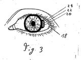
- FIG. 3 shows a front view of the suction ring without attached functional element in use.
- the suction ring includes a vacuum supply 20 connected to the suction portion 4, a vacuum supply 22 connected to the suction portion 10, and a vacuum supply 24 connected to the suction portion 6.
- the suction ring does not have to be substantially circular. It can also be designed, for example, as an elliptical ring or polygon ring.
- FIGS. 4 and 5 show a comparative example with a suction ring 116, a support member 102, an applanation element 104, a feeder 110 with at least one vacuum line and a power supply and a signal connection for at least one measuring means.
- a suction ring 116 At the bottom of the suction ring 116 is a first suction region 128, with which the suction ring 116 is fixed relative to the eye 122.
- the suction ring 116 can fix the holding element 102 via a second suction region 124 in which a negative pressure prevails.
- the holding element 102 fixes the applanation element 104 via a third, optional suction region 126.
- the radiation of a laser system (not shown), for example a femtosecond laser system, is coupled in by the applanation element 104.
- the applanation element can also be designed as a lens.
- the applanation element 104 abuts the cornea of the eye 122 at its lower end, thereby determining the position of the cornea.
- the mechanical guides 106 may include a force sensor (not shown). Furthermore, the force sensor can be arranged on the mechanical guides, in which case the optics of the laser are coupled to the force sensors.
- the force sensor may for example be a piezoelectric sensor or it may be constructed by means of strain gauges.
- the measuring means can be provided by microelectromechanical systems (MEM systems).
- MEM systems microelectromechanical systems
- At the edge of the applanation element 104 is a plurality of fiber sensors 108 for performing a spectroscopic method, for example in the near infrared range, and / or for carrying out a method for determining the light scattering.
- Properties of the cornea for example its water content, can be determined with these fiber sensors.
- the transparency of the cornea can also be determined.
- a separate transparency sensor 114 is provided, which determines its transparency, for example by determining the light scattering of the cornea.
- a mechanical spectroscopy device 112 determines, for example due to mechanical resonance, the biomechanical properties of the cornea.
- the device is supplied with negative pressure. Furthermore, a power supply is ensured with the feed device 110, and the measurement signals of the measuring means are transmitted to an evaluation device (not shown) via an electrical cable, a glass fiber and / or radio.
- contact elements may be provided to transmit electrical signals and to provide a power supply.
- position measuring means 120 are further provided to determine the position of the suction ring 116 and the support member 102 in space.
- the position measuring means 120 may be, for example, acoustic or optical sensors that determine the position relative to a reference geometry.
- the position sensors 120 may be purely passive sensors which receive a beam emitted by a reference location, the position of the suction ring 116 or of the support element 102 being determined on the basis of the received signal.
- the position-measuring means 120 may be purely active elements that have an optical or acoustic Send out beam, which is received by a corresponding receiving device at a reference location, wherein on the basis of the received signal, the position of the position measuring means 120 is determined in space.
- the support member 102 and reference marks can be arranged, which are detected by a camera arranged in space.
- optical sensors can be arranged in the interior of the eye-suction device, which detect the position of the eye. With the aid of the detected position of the eyes relative to the suction ring 116 and the position of the suction ring in the space detected via the position measuring means 120, the position of the eye 122 in space can be determined.
- the means for determining the position of the suction ring in the space may be coupled to a position control (not shown) of a treatment couch or a position control (not shown) of a laser system.
- the suction ring 116 touches the eye in use.
- a force sensor 118 is integrated to measure the force acting on the eye, from which the intraocular pressure can be determined.
- a plurality of force sensors 118 may be arranged. Thereby, a force profile along the circumference of the suction ring 116 can be created, whereby the corneal profile can be determined and accordingly the intraocular pressure can be determined more accurately.
- the suction ring 116 or the support member 102 may further include a fourth suction area (not shown) that evacuates the area between the applanation element and the cornea so that the cornea of the eye 122 securely abuts the applanation element 104.
- the suction ring 116 and the support member 102 may be integrally formed or positively or positively connected.
- the present invention has the advantage that it provides a redundancy, since on the one hand the suction ring is sucked to the eye and on the other hand a part of the cornea is sucked to a functional element or an element arranged thereon. Furthermore, the invention has the advantage that before, during and / or after the operation, the surgeon can easily change a functional element, for example a lens, an applanation lens or a connection area for the optics of a laser system, without the use of a complicated tool.
- the invention also has the advantage that for arranging the functional element No mechanical fasteners are required, which helps miniaturize the eye-suction device and reduce its weight. Since no mechanical fasteners are required, the eye-suction can be made of fewer components and simpler, whereby the surgeon receives a better view of the surgical field and the risk of failure is reduced.
- each of the suction areas can be divided into a plurality of self-sufficient suction areas, whereby a further redundancy with increased security arises.
- the present invention has the advantage that it provides measurement data of the eye before, during and / or after an operation.
- the invention provides measurement data relating to the intraocular pressure, the position of the suction ring in space, the mechanical force acting on an eye, measurement data of the cornea, for example its water content, its biomechanical properties and its transparency. Furthermore, no additional gauges need to be provided to monitor the eye during surgery.
Description
Die Erfindung betrifft eine Vorrichtung für die ophthalmologische Chirurgie.The invention relates to a device for ophthalmic surgery.
Gepulste Laserstrahlung wird in der Augenchirurgie beispielsweise zum Anbringen von Schnitten in der Hornhaut (Kornea) oder zum Abtrag (Ablation) von Gewebe aus der Hornhaut verwendet. Die eingestrahlte Laserstrahlung bewirkt im Hornhautgewebe einen photodisruptiven bzw. photoablativen Prozess, der zur Gewebetrennung bzw. zur Entfernung von Gewebematerial führt. Derartige Bearbeitungen der Kornea finden beispielsweise im Rahmen von refraktiven Verfahren zur Minderung oder vollständigen Behebung von Fehlsichtigkeiten des Auges statt, bei denen die Kornea neu geformt wird und hierdurch ihre Brechungseigenschaften verändert werden.Pulsed laser radiation is used in eye surgery, for example, for applying corneal sections (cornea) or for ablation of tissue from the cornea. The irradiated laser radiation causes a photodisruptive or photoablative process in the corneal tissue, which leads to tissue separation or removal of tissue material. Such treatments of the cornea take place, for example, in the context of refractive methods for the reduction or complete elimination of refractive errors of the eye, in which the cornea is reshaped and thereby its refractive properties are changed.
Das dominierende refraktive Verfahren der Hornhautchirurgie ist die sogenannte LASIK (Laser in situ Keratomileusis). Hierbei wird aus der Hornhaut entweder mechanisch (mittels einer oszillierenden Schneidklinge in einem sogenannten Mikrokeratom) oder optisch (mittels Laserstrahlung, z.B. mittels Femtosekunden-Lasersysteme) ein kleiner Deckel herausgeschnitten, der mit einem Teil seines Randes noch an der Hornhaut hängt. Anschließend wird dieser üblicherweise auch als Flap bezeichnete Deckel zur Seite geklappt, wodurch das darunter liegende Stroma zugänglich wird. Mit Laserstrahlung wird dann nach Maßgabe eines für den jeweiligen Patienten ermittelten Ablationsprofils Stromagewebe abgetragen. Der Deckel wird danach wieder zurückgeklappt, wodurch die Wunde relativ schnell verheilen kann.The dominant refractive procedure of corneal surgery is the so-called LASIK (laser in situ keratomileusis). Here, a small lid is cut out of the cornea either mechanically (by means of an oscillating cutting blade in a so-called microkeratome) or optically (by means of laser radiation, for example by femtosecond laser systems), which still hangs on the cornea with part of its edge. Subsequently, this lid, which is usually also referred to as a flap, is folded aside so that the underlying stroma becomes accessible. With laser radiation stromal tissue is then removed in accordance with an ablation profile determined for the respective patient. The lid is then folded back, allowing the wound to heal relatively quickly.
Für eine präzise Einkopplung der Laserstrahlung in das Auge ist hierbei bekannt, das Auge mittels einer Fixationsvorrichtung zu fixieren, welche durch Unterdruck am Auge angesaugt wird. Die Fixationsvorrichtung kann ein als Einkoppelelement für die Laserstrahlung dienendes Glas aufweisen. Derartige Fixationsvorrichtungen werden auch als Saugringe bezeichnet.For a precise coupling of the laser radiation into the eye, it is known to fix the eye by means of a fixation device, which is sucked by negative pressure on the eye. The fixation device may have a serving as a coupling element for the laser radiation glass. Such fixation devices are also referred to as suction rings.
Sobald der Saugring am Auge eines Patienten angeordnet und mittels eines Unterdruckes an dem Auge fixiert ist, wird mittels Impulsen eines Femtosekunden-Lasers Energie in das Hornhautinnere eingebracht. Dadurch wird in der Hornhaut ein Schnitt erzeugt, der Flap kann aufgeklappt werden und die Korrektur der Fehlsichtigkeit kann durch einen definierten Abtrag von freigelegtem Hornhautgewebe erfolgen.Once the suction ring is arranged on the eye of a patient and fixed by means of a negative pressure on the eye, energy is introduced into the interior of the cornea by means of pulses of a femtosecond laser. As a result, a cut is made in the cornea, the flap can be unfolded and the correction of defective vision can be achieved by a defined removal of exposed corneal tissue.
Saugringe per se sind dem Fachmann bekannt, beispielsweise offenbaren die
Die
Die
Erfindungsgemäß ist in Übereinstimmung mit Anspruch 1 eine Vorrichtung für die Augenchirurgie vorgesehen, umfassend einen auf ein zu behandelndes Auge aufsetzbaren Saugring mit einem ersten Saugbereich, der dazu ausgebildet ist, durch Unterdruckerzeugung in dem ersten Saugbereich den Saugring an das Auge anzusaugen, und ein an den Saugring ankoppelbares Funktionselement mit einem optischen Element zur Anlage der Hornhaut des Auges. Die Neuerung besteht hierbei darin, dass der Saugring einen weiteren Saugbereich aufweist, welcher dazu augebildet ist, durch Unterdruckerzeugung in dem weiteren Saugbereich das Funktionselement an den Saugring anzusaugen und die Hornhaut an das optische Element anzusaugen.According to the invention, a device for eye surgery is provided in accordance with
Bevorzugte Weiterbildungen dieses Erfindungsgedankens finden sich in den abhängigen Ansprüchen 2 bis 13.Preferred developments of this inventive concept can be found in the
Der Saugbereich kann beispielsweise durch eine Öffnung oder eine Ausnehmung gebildet sein, in der im Einsatz ein Unterdruck herrscht. Der Unterdruck kann beispielsweise durch eine mit dem Saugbereich verbundene Saugpumpe erzeugt werden. Es ist jedoch auch möglich, dass der Unterdruck beim Ankoppeln des Funktionselementes an den Saugring oder beim Ankoppeln des Saugrings an das Auge automatisch entsteht, indem beispielsweise eine Dichtlippe verschoben wird, so dass ein evakuierter Saugbereich entsteht.The suction region can be formed, for example, by an opening or a recess in which there is a negative pressure in use. The negative pressure can be generated for example by a suction pump connected to the suction. However, it is also possible that the negative pressure during coupling of the functional element to the suction ring or when coupling the suction ring to the eye automatically arises, for example, by a sealing lip is moved, so that an evacuated suction arises.
Das Funktionselement umfasst ein optisches Element, beispielsweise ein Glas oder eine Linse, durch welche die Laserstrahlung in die Hornhaut eingebracht wird. Das optische Element kann eine Linse oder eine Applanationsplatte sein. Das Funktionselement kann ein Halterungselement sein, das dazu ausgebildet ist, dass weitere Elemente daran angeordnet werden können. Das optische Element kann an dem Halterungselement angeordnet sein. Dadurch entsteht eine besonders vielseitig einsetzbare Vorrichtung, da das optische Element sehr einfach ausgewechselt werden kann. Das Funktionselement kann dazu ausgebildet sein, mit einer optischen Einrichtung gekoppelt zu werden. Die optische Einrichtung kann ein Lasersystem, beispielsweise ein Femtosekunden-Lasersystem, mit einer dazugehörigen Optik sein. Das Funktionselement kann auch ein eingangs genanntes mechanisches Mikrokeratom sein. Das Funktionselement kann auch ein Adaptionskegel sein, mit dem der Saugring an eine ophthalmologische Einrichtung gekoppelt wird. Das Funktionselement kann sowohl zur Halterung eines Applanationselementes als auch zum Koppeln der Augensaugeinrichtung mit der ophthalmologischen Einrichtung vorgesehen sein. Im Folgenden wird ein derartiges Funktionselement als Halterungselement bezeichnet.The functional element comprises an optical element, for example a glass or a lens, through which the laser radiation is introduced into the cornea. The optical element may be a lens or an applanation plate. The functional element may be a support element which is designed so that further elements can be arranged thereon. The optical element can be arranged on the support element. This creates a particularly versatile device, since the optical element can be easily replaced. The functional element can be designed to be coupled to an optical device. The optical device may be a laser system, such as a femtosecond laser system, with associated optics. The functional element can also be an initially mentioned mechanical microkeratome. The functional element can also be an adaptation cone with which the suction ring is coupled to an ophthalmological device. The functional element can be provided both for holding an applanation element and for coupling the eye-suction device with the ophthalmological device. In the following, such a functional element is referred to as a holding element.
Die Vorrichtung kann eine erste Unterdruckzuführung, die mit dem ersten Saugbereich verbunden ist, und eine dritte Unterdruckzuführung, die mit einem dritten Saugbereich verbunden ist, umfassen. Der dritte Saugbereich ist an dem Saugring oder dem Funktionselement angeordnet und ist dazu ausgebildet, im Einsatz das Funktionselement an den Saugring zu saugen. Die Unterdruckzuführungen können an eine oder mehrere Saugpumpen angeschlossen sein. Im Einsatz kann in der ersten Unterdruckzuführung ein anderer Unterdruck herrschen als in der dritten Unterdruckzuführung, wodurch sich unterschiedliche Unterdrücke im ersten und im dritten Saugbereich ergeben. Dadurch ist es möglich, das Funktionselement sicher mit der Augensaugeinrichtung zu koppeln, ohne dass dabei im ersten Saugbereich ein so hoher Unterdruck erzeugt wird, dass das Auge verletzt werden könnte.The apparatus may include a first vacuum supply connected to the first suction region and a third vacuum supply connected to a third suction region. The third suction region is arranged on the suction ring or the functional element and is designed to suck in use the functional element to the suction ring. The vacuum feeds can be connected to one or more suction pumps. In use, a different negative pressure prevail in the first vacuum feed than in the third vacuum feed, resulting in different negative pressures in the first and in the third suction region. This makes it possible to securely couple the functional element to the eye-suction device, without causing such a high negative pressure in the first suction region that the eye could be injured.
Die Vorrichtung kann derart ausgebildet sein, dass im Einsatz zumindest ein Bereich der Hornhaut eines Auges an dem Funktionselement und/oder an einem daran angeordneten Element anliegt. Dadurch ergibt sich eine genaue Fixierung der Hornhaut, was einen sicheren Operationsvorgang sicherstellt. Der weitere Saugbereich steht im Einsatz mit der Oberfläche des Funktionselementes und/oder mit der Oberfläche des daran befestigen Elementes, an dem/denen im Einsatz die Hornhaut des Auges anliegt, in Fluidverbindung . Dadurch wird die Hornhaut besonders gut in ihrer Position festgelegt, da der Bereich zwischen der Hornhaut und dem Funktionselement bzw. einem an dem Halterungselement angeordneten Element evakuiert wird bzw. unter einem Unterdruck steht. Ferner ist es möglich, den in dem Bereich zwischen der Hornhaut und dem Funktionselement und/oder einem daran angeordneten Element herrschenden Unterdruck unabhängig vom Unterdruck im ersten und dritten Saugbereich einzustellen. Dadurch wird die Verletzungsgefahr minimiert und/oder der Behandlungskomfort für einen Patienten erhöht, da sich die Kraft, mit der die Augensaugeinrichtung an das Auge gesaugt wird, von der Kraft unterscheiden kann, mit der die Hornhaut an das Funktionselement und/oder an ein daran angeordnetes Element gesaugt wird. Zudem entsteht auch eine besonders sichere Vorrichtung, die eine Redundanz aufweist, da zwei Unterdrucksysteme verwendet werden, um einerseits den Saugring am Auge zu fixieren und andererseits die Hornhaut an einem Funktionselement und/oder an einem daran angeordneten Element zu fixieren.The device can be designed such that in use at least a portion of the cornea of an eye rests against the functional element and / or on an element arranged thereon. This results in an accurate fixation of the cornea, which ensures a safe surgical procedure. The further suction region is in fluid communication with the surface of the functional element and / or with the surface of the element attached thereto, on which the cornea of the eye rests in use. As a result, the cornea is set particularly well in its position, since the region between the cornea and the functional element or an element arranged on the retaining element is evacuated or is under negative pressure. Furthermore, it is possible to set the negative pressure prevailing in the region between the cornea and the functional element and / or an element arranged thereon independently of the negative pressure in the first and third suction regions. This minimizes the risk of injury and / or increases patient comfort, as the force applied to the eye-suction device increases the eye is sucked, can distinguish from the force with which the cornea is sucked to the functional element and / or to an element arranged thereon. In addition, a particularly secure device that has a redundancy, since two vacuum systems are used to fix one hand, the suction ring on the eye and on the other hand to fix the cornea to a functional element and / or on an element arranged thereon.
Bei einer vereinfachten Ausführungsform kann die Unterdruckzuführung des weiteren Saugbereichs mit der ersten oder der dritten Unterdruckzuführung in Fluidverbindung stehen.In a simplified embodiment, the vacuum feed of the further suction region may be in fluid communication with the first or the third vacuum feed.
Die Vorrichtung kann zumindest ein Messmittel umfassen. Der Ausdruck Messmittel umfasst in diesem Kontext auch das qualitative und/oder quantitative Bestimmen oder Ermitteln einer geometrischen, physikalischen und/oder chemischen Größe.The device may comprise at least one measuring means. The term measuring means in this context also includes the qualitative and / or quantitative determination or determination of a geometric, physical and / or chemical quantity.
Zumindest eines der Messmittel der Vorrichtung kann dazu ausgebildet sein, eine Messung bezüglich einer Eigenschaft des Auges durchzuführen. Das Messmittel kann dazu ausgebildet sein, den Augeninnendruck zu bestimmen, wobei der Augeninnendruck beispielsweise mittels taktiler, mechanischer, akustischer und optischer Verfahren, insbesondere auch Resonanzverfahren, ermittelt werden kann.At least one of the measuring means of the device can be designed to perform a measurement with respect to a property of the eye. The measuring means can be designed to determine the intraocular pressure, wherein the intraocular pressure can be determined, for example, by means of tactile, mechanical, acoustic and optical methods, in particular also resonance methods.
Zumindest ein Messmittel der Vorrichtung kann dazu ausgebildet sein, Eigenschaften der Hornhaut des Auges zu messen. Das Messmittel zum Messen der Eigenschaften der Hornhaut des Auges kann den Wassergehalt der Hornhaut, eine biomechanische Eigenschaft der Hornhaut und/oder die Transparenz der Hornhaut messen. Der Wassergehalt kann beispielsweise mittels eines optischen Spektrometers bestimmt werden, die biomechanischen Eigenschaften der Hornhaut können beispielsweise durch mechanische Spektroskopieverfahren bestimmt werden und die Transparenz der Hornhaut kann durch Lichtstreuung bestimmt werden.At least one measuring device of the device can be designed to measure properties of the cornea of the eye. The measuring means for measuring the properties of the cornea of the eye can measure the water content of the cornea, a biomechanical property of the cornea and / or the transparency of the cornea. The water content can be determined, for example, by means of an optical spectrometer, the biomechanical properties of the cornea can be determined, for example, by mechanical spectroscopy methods and the transparency of the cornea can be determined by light scattering.
Die Vorrichtung kann ein Messmittel zum Messen einer auf das Auge wirkenden Größe umfassen. Das Messmittel zum Messen einer auf das Auge wirkenden Größe kann eine auf das Auge wirkende Kraft messen. Dazu können Drucksensoren, beispielsweise piezoelektrische Drucksensoren, oder Kraftsensoren in den Saugring integriert werden. Ferner ist es möglich, mikroelektromechanische Systeme (MEM-Systeme) zu verwenden, die beispielsweise an dem optischen Element angeordnet sind, über das die Laserstrahlung eingebracht wird.The device may comprise a measuring means for measuring a quantity acting on the eye. The measuring means for measuring a quantity acting on the eye can measure a force acting on the eye. For this purpose, pressure sensors, for example piezoelectric pressure sensors, or force sensors can be integrated into the suction ring. Furthermore, it is possible to use microelectromechanical systems (MEM systems) to be used, for example, are arranged on the optical element, via which the laser radiation is introduced.
Die Vorrichtung kann zumindest ein Messmittel zur Messung einer Eigenschaft des Auges und/oder der Augensaugeinrichtung bezüglich der Umgebung umfassen. Das Messmittel zum Messen einer Eigenschaft des Auges und/oder der Augensaugeinrichtung bezüglich der Umgebung kann beispielsweise die Position des Auges und/oder der Augensaugeinrichtung im Raum messen. Das Mittel zum Messen der Eigenschaft des Auges und/oder des Saugringes gegenüber der Umgebung kann dazu ausgelegt sein, mit Positionierungsmitteln für eine Behandlungsliege und/oder Positionierungsmitteln für Laserstrahlung zusammenzuwirken. Dadurch kann sichergestellt werden, dass sich das Auge immer in der korrekten Position befindet und die Laserstrahlung an der korrekten Position und unter dem korrekten Winkel auf die Hornhaut des Auges auftrifft. Die Messung der Position des Auges und/oder des Saugringes kann auf einer mechanischen, hochfrequenzbasierten, akustischen oder (dreidimensionalen) optischen Positionserkennung beruhen. Die Messmittel können an einem Funktionselement angeordnet sein, das an den Saugring gesaugt wird.The device may comprise at least one measuring device for measuring a property of the eye and / or the eye-suction device with respect to the environment. The measuring means for measuring a property of the eye and / or the eye-suction device with respect to the environment may, for example, measure the position of the eye and / or the eye-suction device in space. The means for measuring the property of the eye and / or the suction ring relative to the environment may be adapted to cooperate with positioning means for a treatment couch and / or positioning means for laser radiation. This will ensure that the eye is always in the correct position and the laser radiation hits the cornea of the eye at the correct position and at the correct angle. The measurement of the position of the eye and / or the suction ring can be based on a mechanical, high-frequency-based, acoustic or (three-dimensional) optical position detection. The measuring means may be arranged on a functional element, which is sucked to the suction ring.
Die Messmittel können dazu ausgelegt sein, ermittelte Messdaten zu übertragen. Die Messdaten können induktiv, über ein Kabel, über eine optische Schnittstelle oder über eine elektromagnetische Schnittstelle übertragen werden. Das Messmittel kann eine Batterie umfassen, induktiv mit Strom versorgt werden oder über eine Zuleitung mit Strom versorgt werden. Das Messmittel kann ferner eine Kommunikationseinrichtung umfassen. Beispielsweise kann das Messmittel als Transponder ausgebildet sein, so dass von außen eine induktive oder elektromagnetische Anregung erfolgt und die Kommunikationseinrichtung des Messmittels die ermittelten Messwerte induktiv oder elektromagnetisch überträgt.The measuring means can be designed to transmit determined measured data. The measured data can be transmitted inductively, via a cable, via an optical interface or via an electromagnetic interface. The measuring means may comprise a battery, be supplied with power inductively or be supplied via a supply line with electricity. The measuring means may further comprise a communication device. For example, the measuring means may be formed as a transponder, so that an inductive or electromagnetic excitation takes place from outside and the communication device of the measuring means transmits the determined measured values inductively or electromagnetically.
Die Erfindung wird nachfolgend anhand der beigefügten Zeichnungen näher erläutert. Es stellen dar:
-
Figur 1 -
Figur 2a einen schematischen, nicht maßstabsgetreuen Schnitt durch eine zweite Ausführungsform der Erfindung; -
Figur 2b einen schematischen, nicht maßstabsgetreuen Schnitt durch eine dritte Ausführungsform der Erfindung; -
Figur 3 -
Figur 4 -
Figur 5 einen schematischen, nicht maßstabsgetreuen Schnitt durch das Vergleichsbeispiel.
-
FIG. 1 a schematic, not to scale section through a first embodiment of the invention; -
FIG. 2a a schematic, not to scale section through a second embodiment of the invention; -
FIG. 2b a schematic, not to scale section through a third embodiment of the invention; -
FIG. 3 a schematic front view of the invention; -
FIG. 4 a perspective, not to scale true view of a comparative example, which comprises a suction ring with a measuring device; and -
FIG. 5 a schematic, not true to scale section through the comparative example.
Ferner umfasst der Saugring 2 einen Saugbereich 6, der ein weiterer Saugbereich im Sinne der Erfindung ist und mit dem Raum zwischen dem Funktionselement 12 und der Hornhaut 19 des Auges 18 in Fluidverbindung steht und diesen zumindest teilweise evakuiert, so dass zumindest ein Teil der Hornhaut an dem Funktionselement 12 anliegt. Der Bereich, an dem die Hornhaut 19 anliegt, kann als Applanationslinse bzw. Applanationsplatte 11 ausgebildet sein. Die Vorrichtung umfasst eine Mehrzahl von Unterdruckzuführungen 20, 22, 24 (in
Die erfindungsgemäße Vorrichtung vermeidet eine Verletzung des Auges, da im Saugbereich 4 ein anderer Unterdruck eingestellt werden kann als im zweiten Saugbereich 10 und/oder im Saugbereich 6. Ferner schafft die vorliegende Erfindung eine Redundanz, da der Saugring 2 sowohl durch den Saugbereich 4 als auch durch den Saugbereich 6 am Auge gehalten wird.The device according to the invention avoids injury to the eye, since a different negative pressure can be set in the
Der Saugbereich 4 ist als umlaufende Nut im Saugring 2 ausgebildet. Es sind jedoch auch andere Ausgestaltungen möglich, beispielsweise eine Mehrzahl von umlaufenden Nuten, eine oder mehrere umlaufende oder nicht umlaufende Einbuchtungen oder eine Mehrzahl von Öffnungen. Der Saugbereich 10 ist durch zwei kreisförmig umlaufende Nuten an der Vorderseite oder Oberseite des Saugring 2 ausgebildet. Auch hier sind die zuvor bezüglich des Saugbereiches 4 beschriebenen Ausgestaltungen möglich. Der Saugbereich 6 wirkt bei der ersten Ausführungsform im Übergangsbereich vom Saugring 2 zum Funktionselement 12. Dadurch kann sichergestellt werden, dass ein Teil der Hornhaut 19 an die Oberfläche des Funktionselementes 12 gesaugt wird.The
Das Funktionselement 12 lässt sich einfach wechseln, ohne dass spezielle Werkzeuge und/oder aufwändige Bedienschritte dafür erforderlich sind. Das Funktionselement 12 kann im Einsatz einfach durch ein anderes ausgetauscht werden, das beispielsweise ein anderes optisches Element 11, Applanationselement 11 und/oder einen anderen Anschlussbereich 13 umfasst.The
Im Gegensatz zur Ausführungsform nach
Durch den Unterdruck im Saugbereich 6 wird die Hornhaut 19 an das am Halterungselement 14 angeordnete optische Element 16 gesaugt.Due to the negative pressure in the
Der Saugring umfasst eine Unterdruckzuführung 20, die mit dem Saugbereich 4 verbunden ist, eine Unterdruckzuführung 22, die mit dem Saugbereich 10 verbunden ist, und eine Unterdruckzuführung 24, die mit dem Saugbereich 6 verbunden ist. Der Saugring muss nicht im Wesentlichen kreisrund sein. Er kann beispielsweise auch als elliptischer Ring oder Polygonring ausgebildet sein.The suction ring includes a
An der Oberseite des Halterungselementes 102 ist eine Mehrzahl von mechanischen Führungen 106 zum Ankoppeln des Strahlenganges des Lasers und/oder eines Verschlussmechanismus ausgebildet. Die mechanischen Führungen 106 können einen Kraftsensor (nicht dargestellt) umfassen. Ferner kann der Kraftsensor an den mechanischen Führungen angeordnet werden, wobei die Optik des Lasers in diesem Fall an die Kraftsensoren gekoppelt wird. Der Kraftsensor kann beispielsweise ein piezoelektrischer Sensor sein oder er kann mittels Dehnungsmessstreifen aufgebaut sein.At the top of the
An dem Applanationselement 104 können Messmittel zum Messen des Augeninnendruckes angeordnet sein. Die Messmittel können durch mikroelektromechanische Systeme (MEM-Systeme) bereitgestellt werden. Am Rand des Applanationselementes 104 befindet sich eine Mehrzahl von Fasersensoren 108 zum Durchführen eines Spektroskopieverfahrens, beispielsweise im nahen Infrarotbereich, und/oder zum Durchführen eines Verfahrens zur Bestimmung der Lichtstreuung. Mit diesen Fasersensoren können Eigenschaften der Hornhaut, beispielsweise deren Wassergehalt, bestimmt werden. Durch die Bestimmung der Lichtstreuung kann auch die Transparenz der Hornhaut bestimmt werden. Hierzu ist ein separater Transparenzsensor 114 vorgesehen, der beispielsweise durch Bestimmung der Lichtstreuung der Hornhaut deren Transparenz ermittelt. Eine mechanische Spektroskopieeinrichtung 112 ermittelt, beispielsweise aufgrund mechanischer Resonanz, die biomechanischen Eigenschaften der Hornhaut. Über die Zuführeinrichtung 110 wird der Vorrichtung Unterdruck zugeführt. Ferner wird mit der Zuführeinrichtung 110 eine Stromversorgung gewährleistet, und die Messsignale der Messmittel werden an eine (nicht gezeigte) Auswerteeinrichtung über ein elektrisches Kabel, eine Glasfaser und/oder Funk übertragen. An dem Applanationselement 104 und dem Halterungselement 102 können Kontaktelemente vorgesehen werden, um elektrische Signale zu übertagen und eine Stromversorgung bereitzustellen.On the
An dem Halterungselement 102 sind ferner Positionsmessmittel 120 vorgesehen, um die Position des Saugrings 116 bzw. des Halterungselementes 102 im Raum zu bestimmen. Die Positionsmessmittel 120 können beispielsweise akustische oder optische Sensoren sein, die die Position gegenüber einer Referenzgeometrie bestimmen. Ferner kann es sich bei den Positionssensoren 120 um rein passive Sensoren handeln, die einen von einem Referenzort ausgestrahlten Strahl empfangen, wobei auf Basis des empfangenen Signals die Position des Saugrings 116 bzw. des Halterungselementes 102 bestimmt wird. Ebenso können die Positionsmessmittel 120 rein aktive Elemente sein, die einen optischen oder akustischen Strahl aussenden, der von einer entsprechenden Empfangseinrichtung an einem Referenzort empfangen wird, wobei auf Basis des empfangenen Signals die Position der Positionsmessmittel 120 im Raum bestimmt wird. An dem Halterungselement 102 können auch Referenzmarken angeordnet sein, die von einer im Raum angeordneten Kamera erfasst werden. Ebenso können im Inneren der Augensaugeinrichtung optische Sensoren angeordnet sein, die die Position des Auges erfassen. Mit Hilfe der erfassten Position der Augen gegenüber dem Saugring 116 und der über die Positionsmessmittel 120 erfassten Position des Saugringes im Raum kann die Position des Auges 122 im Raum bestimmt werden.On the
Die Mittel zum Bestimmen der Position des Saugringes im Raum können mit einer (nicht gezeigten) Positionssteuerung einer Behandlungsliege oder einer (nicht gezeigten) Positionssteuerung eines Lasersystems gekoppelt werden.The means for determining the position of the suction ring in the space may be coupled to a position control (not shown) of a treatment couch or a position control (not shown) of a laser system.
Der Saugring 116 berührt im Einsatz das Auge. In den Saugring 116 ist ein Kraftsensor 118 integriert, um die auf das Auge wirkende Kraft zu messen, woraus der Augeninnendruck bestimmt werden kann. Im Saugring116 kann eine Mehrzahl von Kraftsensoren 118 angeordnet sein. Dadurch kann ein Kraftprofil entlang dem Umfang des Saugrings 116 erstellt werden, wodurch das Hornhautprofil ermittelt werden kann und demgemäss der Augeninnendruck genauer ermittelt werden kann.The
Der Saugring 116 oder das Halterungselement 102 kann ferner einen vierten Saugbereich (nicht gezeigt) umfassen, der den Bereich zwischen dem Applanationselement und der Hornhaut evakuiert, damit die Hornhaut des Auges 122 sicher an dem Applanationselement 104 anliegt.The
Der Saugring 116 und das Halterungselement 102 können integral ausgebildet sein oder kraft- oder formschlüssig verbunden sein.The
Die vorliegende Erfindung hat den Vorteil, dass sie eine Redundanz schafft, da einerseits der Saugring an das Auge gesaugt wird und andererseits ein Teil der Hornhaut an ein Funktionselement oder ein daran angeordnetes Element gesaugt wird. Ferner hat die Erfindung den Vorteil, dass der Operateur vor, während und/oder nach der Operation ohne Verwendung eines aufwändig zu bedienenden Werkzeuges ein Funktionselement, beispielsweise eine Linse, eine Applanationslinse oder einen Anschlussbereich für die Optik eines Lasersystems, einfach wechseln kann. Die Erfindung hat ferner den Vorteil, dass zum Anordnen des Funktionselementes keine mechanischen Befestigungselemente erforderlich sind, was dazu beiträgt, die Augensaugeinrichtung zu miniaturisieren und deren Gewicht zu reduzieren. Da keine mechanischen Befestigungselemente erforderlich sind, kann die Augensaugeinrichtung aus weniger Bauteilen und einfacher aufgebaut werden, wodurch der Operateur eine bessere Sicht auf das Operationsfeld erhält und das Ausfallsrisiko reduziert wird.The present invention has the advantage that it provides a redundancy, since on the one hand the suction ring is sucked to the eye and on the other hand a part of the cornea is sucked to a functional element or an element arranged thereon. Furthermore, the invention has the advantage that before, during and / or after the operation, the surgeon can easily change a functional element, for example a lens, an applanation lens or a connection area for the optics of a laser system, without the use of a complicated tool. The invention also has the advantage that for arranging the functional element No mechanical fasteners are required, which helps miniaturize the eye-suction device and reduce its weight. Since no mechanical fasteners are required, the eye-suction can be made of fewer components and simpler, whereby the surgeon receives a better view of the surgical field and the risk of failure is reduced.
Es versteht sich, dass jeder der Saugbereiche in eine Mehrzahl von autarken Saugbereichen aufgeteilt werden kann, wodurch eine weitere Redundanz mit erhöhter Sicherheit entsteht.It is understood that each of the suction areas can be divided into a plurality of self-sufficient suction areas, whereby a further redundancy with increased security arises.
Die vorliegende Erfindung hat den Vorteil, dass sie vor, während und/oder nach einer Operation Messdaten des Auges liefert. Die Erfindung liefert Messdaten bezüglich des Augeninnendrucks, der Position des Saugringes im Raum, der mechanischen Kraft, die auf ein Auge wirkt, Messdaten der Hornhaut, beispielsweise deren Wassergehalt, deren biomechanische Eigenschaften und deren Transparenz. Ferner müssen keine zusätzlichen Messgeräte bereitgestellt werden, um das Auge während einer Operation zu überwachen.The present invention has the advantage that it provides measurement data of the eye before, during and / or after an operation. The invention provides measurement data relating to the intraocular pressure, the position of the suction ring in space, the mechanical force acting on an eye, measurement data of the cornea, for example its water content, its biomechanical properties and its transparency. Furthermore, no additional gauges need to be provided to monitor the eye during surgery.
Die Erfindung wurde mittels mehrerer Ausführungsformen beschrieben. Der Fachmann versteht, dass die Merkmale und Merkmalskombinationen der verschiedenen Ausführungsformen kombiniert werden können.The invention has been described by means of several embodiments. It will be understood by those skilled in the art that the features and feature combinations of the various embodiments may be combined.
Claims (13)
- Apparatus for eye surgery, comprising:- a suction ring (2) adapted for being placed onto an eye to be treated and having a first suction portion (4) configured to suck the suction ring to the eye (18) by generating a vacuum in the first suction portion; and- a function member (14) adapted for coupling to the suction ring and having an optical element for contacting the cornea of the eye, the suction ring comprising a further suction portion (6) configured to suck the function member to the suction ring by generating a vacuum in the further suction portion;characterised in that the further suction portion is configured to suck the cornea to the optical element by generation of a vacuum in the further suction portion.
- Apparatus of claim 1, characterised in that the function member (14) comprises a connection portion for coupling to a laser system.
- Apparatus of claim 1 or 2, characterised in that the function member (14) is a support member having a recess in which the optical element (16) is accommodated.
- Apparatus of any one of claims 1 to 3, characterised in that the optical element is a lens.
- Apparatus of any one of claims 1 to 3, characterised in that the optical element is plate.
- Apparatus of any one preceding claim, characterised in that the suction ring (2) comprises a first vacuum supply (20) connected to the first suction portion (4) and a second vacuum supply (24) connected to the further suction portion (6).
- Apparatus of any one preceding claim, characterised in that the vacuum in the further suction portion (6) is adjustable independent of the vacuum in the first suction portion (4).
- Apparatus of any one preceding claim, characterised by at least one measuring means (120) provided on at least one of the suction ring (116) and the function member (102), for measuring a property of at least one of the eye and the suction ring with respect to the environment.
- Apparatus of claim 8, characterised in that at least one of the measuring means (120) is designed as a position measuring means for measuring the spatial position of at least one of the suction ring (116) and the function member (102).
- Apparatus of claim 9, characterised in that the position measuring means (120) is configured to cooperate with at least one of positioning means for a treatment chair and positioning means for a laser radiation.
- Apparatus of any one of claims 8 to 10, characterised in that the measuring means (120) is hermetically sealed facilitating disinfection and/or sterilization.
- Apparatus of any one of claims 8 to 11, characterised in that the measuring means (120) is configured to transmit obtained measurement data.
- Apparatus of claim 12, characterised in that the measuring means (120) further comprises a communication device.
Priority Applications (20)
| Application Number | Priority Date | Filing Date | Title |
|---|---|---|---|
| EP07005280A EP1970034B1 (en) | 2007-03-14 | 2007-03-14 | Apparatus for connecting an element to an eye |
| ES09012579T ES2720365T3 (en) | 2007-03-14 | 2007-03-14 | Apparatus for coupling an element to the eye |
| ES07005280T ES2336611T3 (en) | 2007-03-14 | 2007-03-14 | APPARATUS FOR THE COUPLING OF AN ELEMENT TO THE EYE. |
| DE502007002400T DE502007002400D1 (en) | 2007-03-14 | 2007-03-14 | Apparatus for coupling an element to the eye |
| EP09012579.0A EP2133048B1 (en) | 2007-03-14 | 2007-03-14 | Apparatus for connecting an element to an eye |
| KR1020097021481A KR101274264B1 (en) | 2007-03-14 | 2008-03-13 | Apparatus for coupling an element onto the eye |
| CA2680072A CA2680072C (en) | 2007-03-14 | 2008-03-13 | Apparatus for coupling an element to the eye |
| CN201210101390.2A CN102697598B (en) | 2007-03-14 | 2008-03-13 | For element being connected to the apparatus on eyes |
| CN2008800080831A CN101646406B (en) | 2007-03-14 | 2008-03-13 | Apparatus for coupling an element to the eye |
| US12/531,217 US8475433B2 (en) | 2007-03-14 | 2008-03-13 | Apparatus for coupling an element to the eye |
| CA2819455A CA2819455C (en) | 2007-03-14 | 2008-03-13 | Apparatus for coupling an element to the eye |
| BR122014017011A BR122014017011B8 (en) | 2007-03-14 | 2008-03-13 | eye surgery device |
| BRPI0808324A BRPI0808324B8 (en) | 2007-03-14 | 2008-03-13 | eye surgery device |
| PCT/EP2008/002014 WO2008110368A1 (en) | 2007-03-14 | 2008-03-13 | Apparatus for coupling an element to the eye |
| MX2009009744A MX2009009744A (en) | 2007-03-14 | 2008-03-13 | Apparatus for coupling an element to the eye. |
| JP2009553076A JP5295134B2 (en) | 2007-03-14 | 2008-03-13 | Device for coupling element to eyeball |
| KR1020127018219A KR101189819B1 (en) | 2007-03-14 | 2008-03-13 | Device for eye surgery |
| RU2009133106/14A RU2463028C2 (en) | 2007-03-14 | 2008-03-13 | Device for fixation of element to eye |
| US13/435,693 US8753321B2 (en) | 2007-03-14 | 2012-03-30 | Apparatus for coupling an element to the eye |
| JP2012288583A JP5525594B2 (en) | 2007-03-14 | 2012-12-28 | Device for coupling element to eyeball |
Applications Claiming Priority (1)
| Application Number | Priority Date | Filing Date | Title |
|---|---|---|---|
| EP07005280A EP1970034B1 (en) | 2007-03-14 | 2007-03-14 | Apparatus for connecting an element to an eye |
Related Child Applications (1)
| Application Number | Title | Priority Date | Filing Date |
|---|---|---|---|
| EP09012579.0A Division EP2133048B1 (en) | 2007-03-14 | 2007-03-14 | Apparatus for connecting an element to an eye |
Publications (2)
| Publication Number | Publication Date |
|---|---|
| EP1970034A1 EP1970034A1 (en) | 2008-09-17 |
| EP1970034B1 true EP1970034B1 (en) | 2009-12-23 |
Family
ID=38110731
Family Applications (2)
| Application Number | Title | Priority Date | Filing Date |
|---|---|---|---|
| EP09012579.0A Active EP2133048B1 (en) | 2007-03-14 | 2007-03-14 | Apparatus for connecting an element to an eye |
| EP07005280A Active EP1970034B1 (en) | 2007-03-14 | 2007-03-14 | Apparatus for connecting an element to an eye |
Family Applications Before (1)
| Application Number | Title | Priority Date | Filing Date |
|---|---|---|---|
| EP09012579.0A Active EP2133048B1 (en) | 2007-03-14 | 2007-03-14 | Apparatus for connecting an element to an eye |
Country Status (12)
| Country | Link |
|---|---|
| US (2) | US8475433B2 (en) |
| EP (2) | EP2133048B1 (en) |
| JP (2) | JP5295134B2 (en) |
| KR (2) | KR101274264B1 (en) |
| CN (2) | CN101646406B (en) |
| BR (2) | BR122014017011B8 (en) |
| CA (2) | CA2680072C (en) |
| DE (1) | DE502007002400D1 (en) |
| ES (2) | ES2720365T3 (en) |
| MX (1) | MX2009009744A (en) |
| RU (1) | RU2463028C2 (en) |
| WO (1) | WO2008110368A1 (en) |
Cited By (1)
| Publication number | Priority date | Publication date | Assignee | Title |
|---|---|---|---|---|
| DE102022114573A1 (en) | 2022-06-09 | 2023-12-14 | Schwind Eye-Tech-Solutions Gmbh | Treatment device and method for controlling a fixation device for fixing a human or animal eye |
Families Citing this family (92)
| Publication number | Priority date | Publication date | Assignee | Title |
|---|---|---|---|---|
| US20120016349A1 (en) * | 2001-01-29 | 2012-01-19 | Amo Development, Llc. | Hybrid ophthalmic interface apparatus and method of interfacing a surgical laser with an eye |
| US8262646B2 (en) | 2006-01-20 | 2012-09-11 | Lensar, Inc. | System and method for providing the shaped structural weakening of the human lens with a laser |
| US10842675B2 (en) | 2006-01-20 | 2020-11-24 | Lensar, Inc. | System and method for treating the structure of the human lens with a laser |
| US9545338B2 (en) | 2006-01-20 | 2017-01-17 | Lensar, Llc. | System and method for improving the accommodative amplitude and increasing the refractive power of the human lens with a laser |
| US9889043B2 (en) | 2006-01-20 | 2018-02-13 | Lensar, Inc. | System and apparatus for delivering a laser beam to the lens of an eye |
| US9427357B2 (en) * | 2007-02-21 | 2016-08-30 | Amo Development, Llc | Preformed lens systems and methods |
| ES2720365T3 (en) * | 2007-03-14 | 2019-07-19 | Wavelight Gmbh | Apparatus for coupling an element to the eye |
| EP2194904A4 (en) | 2007-09-10 | 2013-03-13 | Alcon Lensx Inc | Apparatus, systems and techniques for interfacing with an eye in laser surgery |
| US8632526B2 (en) * | 2007-11-07 | 2014-01-21 | Amo Development, Llc | System and method of interfacing a surgical laser with an eye |
| ES2442002T3 (en) * | 2008-06-20 | 2014-02-07 | Wavelight Gmbh | Device for cutting a piece of tissue with focused laser radiation |
| US8480659B2 (en) | 2008-07-25 | 2013-07-09 | Lensar, Inc. | Method and system for removal and replacement of lens material from the lens of an eye |
| US8500723B2 (en) | 2008-07-25 | 2013-08-06 | Lensar, Inc. | Liquid filled index matching device for ophthalmic laser procedures |
| RU2485923C2 (en) * | 2008-08-25 | 2013-06-27 | Уэйвлайт Гмбх | Method of ensuring contact of eye with laser device |
| PT2451415T (en) * | 2009-07-10 | 2018-05-22 | Wavelight Gmbh | Device for cutting a tissue part of an eye by means of laser radiation |
| US10624787B2 (en) | 2009-07-10 | 2020-04-21 | Alcon Inc. | Apparatus for cutting a tissue section of an eye by laser radiation |
| US8382745B2 (en) | 2009-07-24 | 2013-02-26 | Lensar, Inc. | Laser system and method for astigmatic corrections in association with cataract treatment |
| US8758332B2 (en) | 2009-07-24 | 2014-06-24 | Lensar, Inc. | Laser system and method for performing and sealing corneal incisions in the eye |
| CN102625685B (en) * | 2009-07-24 | 2015-11-25 | 能斯雅有限公司 | For the liquid storage interface equipment of ophthalmology laser surgery |
| WO2011011727A1 (en) | 2009-07-24 | 2011-01-27 | Lensar, Inc. | System and method for providing laser shot patterns to the lens of an eye |
| US8617146B2 (en) | 2009-07-24 | 2013-12-31 | Lensar, Inc. | Laser system and method for correction of induced astigmatism |
| EP2456385B1 (en) | 2009-07-24 | 2015-07-22 | Lensar, Inc. | System for performing ladar assisted procedures on the lens of an eye |
| US20110190739A1 (en) * | 2010-01-29 | 2011-08-04 | Lensar, Inc. | Servo controlled docking force device for use in ophthalmic applications |
| CN102843955A (en) * | 2010-02-01 | 2012-12-26 | 雷萨公司 | Purkinjie image-based alignment of suction ring in ophthalmic applications |
| CN103037802B (en) * | 2010-03-31 | 2016-08-24 | 奥库杰克特有限责任公司 | Equipment and method for intraocular drug delivery |
| US9408746B2 (en) | 2010-03-31 | 2016-08-09 | Ocuject, Llc | Device and method for intraocular drug delivery |
| US20130218145A1 (en) | 2010-05-10 | 2013-08-22 | Tel Hashomer Medical Research Infrastructure And Services Ltd. | System and method for treating an eye |
| US8845624B2 (en) * | 2010-06-25 | 2014-09-30 | Alcon LexSx, Inc. | Adaptive patient interface |
| EP2611400B1 (en) * | 2010-09-02 | 2020-04-29 | Optimedica Corporation | Patient interface for ophthalmologic diagnostic and interventional procedures |
| EP4205633A1 (en) | 2010-10-15 | 2023-07-05 | Lensar, Inc. | System and method of scan controlled illumination of structures within an eye |
| USD694890S1 (en) | 2010-10-15 | 2013-12-03 | Lensar, Inc. | Laser system for treatment of the eye |
| USD695408S1 (en) | 2010-10-15 | 2013-12-10 | Lensar, Inc. | Laser system for treatment of the eye |
| DE102011006085A1 (en) | 2011-03-25 | 2012-09-27 | Carl Zeiss Meditec Ag | Ophthalmic device |
| US10463541B2 (en) | 2011-03-25 | 2019-11-05 | Lensar, Inc. | System and method for correcting astigmatism using multiple paired arcuate laser generated corneal incisions |
| US9044302B2 (en) | 2011-10-21 | 2015-06-02 | Optimedica Corp. | Patient interface for ophthalmologic diagnostic and interventional procedures |
| US20130102895A1 (en) * | 2011-10-21 | 2013-04-25 | Optimedica Corporation | Patient interface for ophthalmologic diagnostic and interventional procedures |
| CA2852947A1 (en) * | 2011-10-21 | 2013-04-25 | Optimedica Corporation | Patient interface for ophthalmologic diagnostic and interventional procedures |
| US8863749B2 (en) | 2011-10-21 | 2014-10-21 | Optimedica Corporation | Patient interface for ophthalmologic diagnostic and interventional procedures |
| US9237967B2 (en) | 2011-10-21 | 2016-01-19 | Optimedica Corporation | Patient interface for ophthalmologic diagnostic and interventional procedures |
| EP2633841B1 (en) | 2012-02-28 | 2017-08-16 | Ziemer Ophthalmic Systems AG | Device for treating eye tissue using pulsed laser beams |
| US9504603B2 (en) | 2012-04-02 | 2016-11-29 | Ocuject, Llc | Intraocular delivery devices and methods therefor |
| US9421129B2 (en) | 2012-04-02 | 2016-08-23 | Ocuject, Llc | Intraocular delivery devices and methods therefor |
| US20130338649A1 (en) * | 2012-06-02 | 2013-12-19 | Nidek Co., Ltd. | Ophthalmic laser surgical apparatus |
| US10314746B2 (en) | 2012-11-02 | 2019-06-11 | Optimedica Corporation | Laser eye surgery system calibration |
| US10285860B2 (en) | 2012-11-02 | 2019-05-14 | Optimedica Corporation | Vacuum loss detection during laser eye surgery |
| US9445946B2 (en) | 2012-11-02 | 2016-09-20 | Optimedica Corporation | Laser eye surgery system |
| US10292863B2 (en) * | 2012-11-02 | 2019-05-21 | Optimedica Corporation | Interface force feedback in a laser eye surgery system |
| US9987165B2 (en) * | 2012-11-02 | 2018-06-05 | Optimedica Corporation | Liquid optical interface for laser eye surgery system |
| US20170056243A1 (en) * | 2012-11-02 | 2017-03-02 | Optimedica Corporation | Free floating patient interface for laser surgery system |
| US9603744B2 (en) | 2012-11-09 | 2017-03-28 | Technolas Perfect Vision Gmbh | Adaptable patient interface |
| US9724238B2 (en) * | 2012-11-30 | 2017-08-08 | Amo Development, Llc | Ophthalmic interface apparatus, method of interfacing a surgical laser with an eye, and support ring for use with a suction ring |
| WO2014094853A1 (en) * | 2012-12-20 | 2014-06-26 | Wavelight Gmbh | Apparatus, interface unit, suction ring and method to monitor corneal tissue |
| US10335315B2 (en) * | 2013-02-01 | 2019-07-02 | Alcon Lensx, Inc. | Bi-radial patient interface |
| JP6402116B2 (en) | 2013-02-26 | 2018-10-10 | ベルキン レーザー リミテッド | Glaucoma treatment system |
| US9398979B2 (en) | 2013-03-11 | 2016-07-26 | Technolas Perfect Vision Gmbh | Dimensional compensator for use with a patient interface |
| US10092393B2 (en) | 2013-03-14 | 2018-10-09 | Allotex, Inc. | Corneal implant systems and methods |
| US20140276674A1 (en) * | 2013-03-15 | 2014-09-18 | Amo Development Llc. | System and method for ophthalmic laser surgery employing eye tracking without eye docking |
| EP4137104A1 (en) * | 2013-03-15 | 2023-02-22 | AMO Development, LLC | Hybrid ophthalmic interface apparatus |
| EP2986258B1 (en) | 2013-04-17 | 2018-11-28 | Optimedica Corporation | Laser fiducials for axis alignment in cataract surgery |
| JP6110487B2 (en) * | 2013-06-14 | 2017-04-05 | バーフェリヒト ゲゼルシャフト ミット ベシュレンクテル ハフツング | Automatic machine setting for customized refractive surgery |
| CA2854507C (en) * | 2013-06-21 | 2017-01-03 | Peter Triebel | An apparatus for performing ophthalmic surgery using a contact element |
| CN105451695B (en) * | 2013-06-25 | 2018-03-02 | Tec晶体有限责任公司 | Device for the lucotherapy of eyes |
| KR101435435B1 (en) * | 2013-07-25 | 2014-09-01 | 주식회사 루트로닉 | Contact lens and apparatus for treating ocular having the same |
| EP3197338B1 (en) | 2014-09-25 | 2020-11-04 | AMO Development, LLC | Methods and systems for corneal topography, blink detection and laser eye surgery |
| DE102014225635A1 (en) * | 2014-12-11 | 2016-06-16 | Carl Zeiss Meditec Ag | Device and method for determining a relative geometric position of an eye |
| DE102014225636A1 (en) * | 2014-12-11 | 2016-06-16 | Carl Zeiss Meditec Ag | Device and method for determining a relative geometric position of an eye |
| US10010449B2 (en) | 2014-12-22 | 2018-07-03 | TECLens, LLC | Corneal crosslinking with oxygenation |
| CA2980118A1 (en) | 2015-03-18 | 2016-09-22 | Optimedica Corporation | Vacuum loss detection during laser eye surgery |
| EP3092985B1 (en) * | 2015-05-15 | 2019-12-18 | WaveLight GmbH | Patient adapter for an eye laser apparatus |
| US10449090B2 (en) | 2015-07-31 | 2019-10-22 | Allotex, Inc. | Corneal implant systems and methods |
| ES2670672T3 (en) * | 2015-11-10 | 2018-05-31 | Novartis Ag | Modular patient adapter for an eye laser device |
| US10219948B2 (en) * | 2016-02-24 | 2019-03-05 | Perfect Ip, Llc | Ophthalmic laser treatment system and method |
| WO2017176850A1 (en) | 2016-04-05 | 2017-10-12 | Amo Development, Llc | Patient interface device for laser eye surgery having light guiding structure for illuminating eye |
| KR102481042B1 (en) * | 2016-04-07 | 2022-12-23 | 렌사르, 인크. | Patient interface device for laser methods and systems |
| EP3260093B1 (en) * | 2016-06-22 | 2021-12-22 | Ziemer Ophthalmic Systems AG | Ophthalmological patient interface |
| US10758118B2 (en) * | 2016-06-30 | 2020-09-01 | Iridex Corporation | Handheld ophthalmic laser system with replaceable contact tips and treatment guide |
| CA3036784A1 (en) * | 2016-09-14 | 2018-03-22 | Optimedica Corporation | Free floating patient interface for laser surgery system |
| RU2631108C1 (en) * | 2016-10-06 | 2017-09-18 | Федеральное государственное автономное учреждение "Межотраслевой научно-технический комплекс "Микрохирургия глаза" имени академика С.Н. Федорова" Министерства здравоохранения Российской Федерации | Tools for corneal flap protection against laser impact during excimer laser surgery |
| AU2016426606B2 (en) | 2016-10-19 | 2023-02-02 | Alcon Inc. | Systems and methods for femtosecond laser ophthalmic surgery docking |
| FR3063217B1 (en) * | 2017-02-24 | 2019-04-05 | Keranova | COUPLING INTERFACE BETWEEN A LASER SOURCE AND A FABRIC TO BE TREATED |
| CA3060966A1 (en) | 2017-04-19 | 2018-10-25 | Amo Development, Llc | Patient interface device for ophthalmic surgical laser system |
| KR20200034951A (en) * | 2017-07-27 | 2020-04-01 | 알콘 인코포레이티드 | Femtosecond laser docking device |
| DE102017215589A1 (en) | 2017-09-05 | 2019-03-07 | Carl Zeiss Meditec Ag | Liquid patient interface |
| DE102017123300A1 (en) | 2017-10-06 | 2019-04-11 | Schwind Eye-Tech-Solutions Gmbh | A patient interface system, method for coupling a patient interface to a patient interface holder, a patient interface, and a patient interface holder |
| EP3723681A2 (en) * | 2017-12-12 | 2020-10-21 | Alcon Inc. | Patient interface for ophthalmic surgery |
| US10864075B2 (en) * | 2017-12-31 | 2020-12-15 | Rxsight, Inc. | Intraocular lens visualization and tracking system |
| JP7454243B2 (en) | 2018-07-02 | 2024-03-22 | ベルキン ヴィジョン リミテッド | System for direct selective laser trabeculoplasty |
| KR102120643B1 (en) * | 2018-10-23 | 2020-06-10 | 한국표준과학연구원 | Measurement apparatus for resistance and power of eyeball movement |
| CA3130426A1 (en) * | 2019-03-27 | 2020-10-01 | Alcon Inc. | System and method of utilizing one or more images of an eye in medical procedures |
| JP7355551B2 (en) | 2019-08-09 | 2023-10-03 | 本田技研工業株式会社 | Control device, control method, and program |
| CN115335013A (en) * | 2020-01-03 | 2022-11-11 | 雷萨公司 | Compact reconfigurable integrated laser phacoemulsification system and method of use |
| CN114848292B (en) * | 2022-04-19 | 2023-12-05 | 南京朔视科技开发有限公司 | Interface unit for fixing eyeballs |
| CN117281684B (en) * | 2023-11-24 | 2024-03-29 | 超目科技(北京)有限公司 | Eyeball adsorption device and eyeball adsorption system |
Family Cites Families (49)
| Publication number | Priority date | Publication date | Assignee | Title |
|---|---|---|---|---|
| US4546773A (en) * | 1981-01-23 | 1985-10-15 | Accutome, Inc. | Apparatus to measure conical thickness |
| US4798599A (en) * | 1984-01-03 | 1989-01-17 | George Thomas | Eye washing method and apparatus |
| DE3433581C2 (en) * | 1984-09-13 | 1986-08-07 | Fa. Carl Zeiss, 7920 Heidenheim | Device for laminating, refractive corneal surgery |
| US4669466A (en) * | 1985-01-16 | 1987-06-02 | Lri L.P. | Method and apparatus for analysis and correction of abnormal refractive errors of the eye |
| US5133708A (en) * | 1988-01-14 | 1992-07-28 | Smith Robert F | Method for controlled corneal ablation |
| US5112328A (en) * | 1988-01-25 | 1992-05-12 | Refractive Laser Research & Development Program, Ltd. | Method and apparatus for laser surgery |
| CH673760A5 (en) * | 1988-02-09 | 1990-04-12 | Yves Dr Med Robert | |
| US5215104A (en) * | 1988-08-16 | 1993-06-01 | Steinert Roger F | Method for corneal modification |
| US6099522A (en) * | 1989-02-06 | 2000-08-08 | Visx Inc. | Automated laser workstation for high precision surgical and industrial interventions |
| US5133726A (en) * | 1990-02-14 | 1992-07-28 | Ruiz Luis A | Automatic corneal shaper |
| US6342053B1 (en) | 1990-07-23 | 2002-01-29 | Laser Biotech, Inc. | Apparatus for cornea reshaping |
| WO1993014817A2 (en) * | 1992-01-15 | 1993-08-05 | Premier Laser Systems, Inc. | Corneal sculpting using laser energy |
| US5549632A (en) | 1992-10-26 | 1996-08-27 | Novatec Laser Systems, Inc. | Method and apparatus for ophthalmic surgery |
| WO1994012131A1 (en) * | 1992-11-20 | 1994-06-09 | Shinseiro Okamoto | Cornea operating method and apparatus |
| US5336215A (en) | 1993-01-22 | 1994-08-09 | Intelligent Surgical Lasers | Eye stabilizing mechanism for use in ophthalmic laser surgery |
| US5496339A (en) * | 1994-05-17 | 1996-03-05 | Koepnick; Russell G. | Universal automated keratectomy apparatus and method |
| US5586980A (en) * | 1994-10-14 | 1996-12-24 | Kremer; Frederic B. | Microkeratome |
| US5643299A (en) * | 1996-01-16 | 1997-07-01 | Sentinel Medical, Inc. | Hydrojet apparatus for refractive surgery |
| US5624456A (en) * | 1996-02-07 | 1997-04-29 | Hellenkamp; Johann F. | Automatic surgical device for cutting a cornea |
| US5828454A (en) * | 1996-07-29 | 1998-10-27 | Gust; Gary R. | Optical heterodyne interferometer for measurement of ocular displacement |
| US6126668A (en) | 1997-04-25 | 2000-10-03 | Innovative Optics, Inc. | Microkeratome |
| RU2170563C2 (en) * | 1997-05-27 | 2001-07-20 | Валерий Григорьевич Боровик | Device for performing ophthalmologic surgical operations |
| RU2130762C1 (en) * | 1997-12-10 | 1999-05-27 | Федоров Святослав Николаевич | Device for performing ophthalmosurgical operations |
| US6143011A (en) * | 1998-04-13 | 2000-11-07 | Surgijet, Inc. | Hydrokeratome for refractive surgery |
| US6254595B1 (en) | 1998-10-15 | 2001-07-03 | Intralase Corporation | Corneal aplanation device |
| WO2000041660A1 (en) | 1999-01-15 | 2000-07-20 | Medjet, Inc. | Corneal microjet cutter with adjustable applanation template |
| US6165189A (en) * | 1999-02-10 | 2000-12-26 | Sis, Ltd. | Microkeratome for performing lasik surgery |
| US6344040B1 (en) | 1999-03-11 | 2002-02-05 | Intralase Corporation | Device and method for removing gas and debris during the photodisruption of stromal tissue |
| RU2160575C1 (en) * | 2000-02-02 | 2000-12-20 | ООО "Медицинский научно-исследовательский офтальмологический центр "НОВЫЙ ВЗГЛЯД" | Method for making refraction-correcting eximer laser intrastromal keratectomy |
| US7090669B2 (en) * | 2000-02-14 | 2006-08-15 | Paul Phillip Van Saarloos | Apparatus and procedure for ultraviolet laser ablation |
| EP1199055A1 (en) | 2000-10-16 | 2002-04-24 | Gebauer GmbH | Blade with amorphous cutting edge |
| US6730073B2 (en) * | 2000-10-20 | 2004-05-04 | Medtronic, Inc. | Method of performing a lasik procedure and tonometer system for use therewith |
| US6899707B2 (en) * | 2001-01-29 | 2005-05-31 | Intralase Corp. | Applanation lens and method for ophthalmic surgical applications |
| US6569153B1 (en) * | 2001-06-28 | 2003-05-27 | Lahaye Leon C. | Multi-function surgical instrument for facilitating ophthalmic laser surgery |
| US6497700B1 (en) * | 2001-06-28 | 2002-12-24 | Lahaye Leon C. | Multi-function surgical instrument for facilitating ophthalmic laser surgery |
| DE60117792T2 (en) | 2001-06-29 | 2006-11-23 | Ecole polytechnique fédérale de Lausanne (EPFL) | DEVICE FOR MEASURING INTRAOCULAR PRESSURE |
| JP4436903B2 (en) * | 2001-12-28 | 2010-03-24 | 株式会社ニデック | Cornea surgery device |
| US20030153904A1 (en) * | 2002-02-13 | 2003-08-14 | Patel Anilbhai S. | Environmental chamber for laser refractive surgery |
| US7141047B2 (en) * | 2002-12-18 | 2006-11-28 | Thomas John | Eye aspirating device and method of use |
| EP1620049B1 (en) | 2003-05-02 | 2007-01-10 | Albert Daxer | Device for cutting the cornea of an eye |
| DE10354025B4 (en) * | 2003-11-19 | 2022-03-24 | Carl Zeiss Meditec Ag | Adapter for mechanically coupling a laser processing device to an object |
| US7402159B2 (en) * | 2004-03-01 | 2008-07-22 | 20/10 Perfect Vision Optische Geraete Gmbh | System and method for positioning a patient for laser surgery |
| US7390089B2 (en) * | 2005-02-25 | 2008-06-24 | 20/10 Perfect Vision Optische Geraete Gmbh | Device and method for aligning an eye with a surgical laser |
| JP4879897B2 (en) | 2005-05-10 | 2012-02-22 | 卓也 片岡 | Ophthalmic laser therapy device |
| US7955324B2 (en) * | 2005-10-21 | 2011-06-07 | Technolas Perfect Vision Gmbh | Cornea contact system |
| US10729585B2 (en) * | 2006-07-19 | 2020-08-04 | Alcon Inc. | Computer program for ophthalmological surgery |
| ES2720365T3 (en) * | 2007-03-14 | 2019-07-19 | Wavelight Gmbh | Apparatus for coupling an element to the eye |
| CN102047153A (en) | 2008-07-15 | 2011-05-04 | 夏普株式会社 | Color filter substrate and liquid crystal display device |
| US10624787B2 (en) * | 2009-07-10 | 2020-04-21 | Alcon Inc. | Apparatus for cutting a tissue section of an eye by laser radiation |
-
2007
- 2007-03-14 ES ES09012579T patent/ES2720365T3/en active Active
- 2007-03-14 EP EP09012579.0A patent/EP2133048B1/en active Active
- 2007-03-14 DE DE502007002400T patent/DE502007002400D1/en active Active
- 2007-03-14 EP EP07005280A patent/EP1970034B1/en active Active
- 2007-03-14 ES ES07005280T patent/ES2336611T3/en active Active
-
2008
- 2008-03-13 CN CN2008800080831A patent/CN101646406B/en not_active Expired - Fee Related
- 2008-03-13 JP JP2009553076A patent/JP5295134B2/en active Active
- 2008-03-13 CA CA2680072A patent/CA2680072C/en not_active Expired - Fee Related
- 2008-03-13 BR BR122014017011A patent/BR122014017011B8/en not_active IP Right Cessation
- 2008-03-13 WO PCT/EP2008/002014 patent/WO2008110368A1/en active Application Filing
- 2008-03-13 KR KR1020097021481A patent/KR101274264B1/en active IP Right Grant
- 2008-03-13 KR KR1020127018219A patent/KR101189819B1/en active IP Right Grant
- 2008-03-13 BR BRPI0808324A patent/BRPI0808324B8/en not_active IP Right Cessation
- 2008-03-13 RU RU2009133106/14A patent/RU2463028C2/en not_active IP Right Cessation
- 2008-03-13 MX MX2009009744A patent/MX2009009744A/en active IP Right Grant
- 2008-03-13 US US12/531,217 patent/US8475433B2/en active Active
- 2008-03-13 CN CN201210101390.2A patent/CN102697598B/en not_active Expired - Fee Related
- 2008-03-13 CA CA2819455A patent/CA2819455C/en not_active Expired - Fee Related
-
2012
- 2012-03-30 US US13/435,693 patent/US8753321B2/en active Active
- 2012-12-28 JP JP2012288583A patent/JP5525594B2/en active Active
Cited By (1)
| Publication number | Priority date | Publication date | Assignee | Title |
|---|---|---|---|---|
| DE102022114573A1 (en) | 2022-06-09 | 2023-12-14 | Schwind Eye-Tech-Solutions Gmbh | Treatment device and method for controlling a fixation device for fixing a human or animal eye |
Also Published As
Similar Documents
| Publication | Publication Date | Title |
|---|---|---|
| EP1970034B1 (en) | Apparatus for connecting an element to an eye | |
| EP2729099B1 (en) | Device and method for a laser-assisted eye surgery treatment system | |
| EP2337534B1 (en) | Device, method and control program for ophthalmologic, particularly refractive, laser surgery | |
| EP2349149B1 (en) | Ophthalmologic laser system | |
| EP1758498B1 (en) | Process and device for sensing the position in space of the optical axis of an eye | |
| DE112008002511T5 (en) | Methods and devices for integrated cataract surgery | |
| EP2306948B1 (en) | Device for ophthalmologic, particularly refractive, laser surgery | |
| EP4041151A1 (en) | Arrangement for laser vitreolysis | |
| WO2013017513A2 (en) | Ophthalmologic laser device and method for preventing and treating aftercataract | |
| DE112008002446T5 (en) | Devices, systems and techniques for coupling with an eye in laser surgery | |
| EP2364105B1 (en) | Ophthalmological measuring system and method for calibrating and/or adjusting the same | |
| EP2654636B1 (en) | Device for processing material of a workpiece and method for calibrating such a device | |
| EP1916977A2 (en) | Contact glass for ophthalmic surgery | |
| EP3454802B1 (en) | Planning device and method for generating control data for an ophthalmic surgery device | |
| WO2010070020A2 (en) | Ophthalmological laser system and operating method | |
| DE102019007148A1 (en) | Arrangement for OCT-supported laser vitreolysis | |
| DE102017207529A1 (en) | Aftercare for eye surgery refraction correction | |
| EP2482770B1 (en) | Device for ophthalmological laser surgery | |
| EP2621421B1 (en) | Device for eye surgery | |
| DE102009052135A1 (en) | Artificial intraocular lens positioning method for use in eye of patient, involves displaying or reflecting positioning of intraocular lens to surgery by real time-image of eyes to be operated | |
| WO2022063961A1 (en) | Assembly for laser treatment of ocular opacities | |
| EP1250884B1 (en) | Apparatus for measuring the intraocular pressure, in particular a tonometer | |
| DE102019135609B4 (en) | Method for controlling an ophthalmic surgical laser and treatment device | |
| EP3585242B1 (en) | Patient interface and method for ensuring the sterility of said patient interface | |
| WO2013045436A1 (en) | Ophthalmic surgical measuring device |
Legal Events
| Date | Code | Title | Description |
|---|---|---|---|
| PUAI | Public reference made under article 153(3) epc to a published international application that has entered the european phase |
Free format text: ORIGINAL CODE: 0009012 |
|
| AK | Designated contracting states |
Kind code of ref document: A1 Designated state(s): AT BE BG CH CY CZ DE DK EE ES FI FR GB GR HU IE IS IT LI LT LU LV MC MT NL PL PT RO SE SI SK TR |
|
| AX | Request for extension of the european patent |
Extension state: AL BA HR MK RS |
|
| 17P | Request for examination filed |
Effective date: 20081023 |
|
| 17Q | First examination report despatched |
Effective date: 20090327 |
|
| AKX | Designation fees paid |
Designated state(s): DE ES FR GB IT |
|
| GRAP | Despatch of communication of intention to grant a patent |
Free format text: ORIGINAL CODE: EPIDOSNIGR1 |
|
| GRAS | Grant fee paid |
Free format text: ORIGINAL CODE: EPIDOSNIGR3 |
|
| GRAA | (expected) grant |
Free format text: ORIGINAL CODE: 0009210 |
|
| AK | Designated contracting states |
Kind code of ref document: B1 Designated state(s): DE ES FR GB IT |
|
| REG | Reference to a national code |
Ref country code: GB Ref legal event code: FG4D Free format text: NOT ENGLISH |
|
| REF | Corresponds to: |
Ref document number: 502007002400 Country of ref document: DE Date of ref document: 20100204 Kind code of ref document: P |
|
| REG | Reference to a national code |
Ref country code: ES Ref legal event code: FG2A Ref document number: 2336611 Country of ref document: ES Kind code of ref document: T3 |
|
| PLBE | No opposition filed within time limit |
Free format text: ORIGINAL CODE: 0009261 |
|
| STAA | Information on the status of an ep patent application or granted ep patent |
Free format text: STATUS: NO OPPOSITION FILED WITHIN TIME LIMIT |
|
| 26N | No opposition filed |
Effective date: 20100924 |
|
| PG25 | Lapsed in a contracting state [announced via postgrant information from national office to epo] |
Ref country code: IT Free format text: LAPSE BECAUSE OF NON-PAYMENT OF DUE FEES Effective date: 20100314 |
|
| REG | Reference to a national code |
Ref country code: FR Ref legal event code: PLFP Year of fee payment: 10 |
|
| REG | Reference to a national code |
Ref country code: FR Ref legal event code: PLFP Year of fee payment: 11 |
|
| REG | Reference to a national code |
Ref country code: FR Ref legal event code: PLFP Year of fee payment: 12 |
|
| PGFP | Annual fee paid to national office [announced via postgrant information from national office to epo] |
Ref country code: CZ Payment date: 20190116 Year of fee payment: 13 |
|
| PGFP | Annual fee paid to national office [announced via postgrant information from national office to epo] |
Ref country code: ES Payment date: 20190401 Year of fee payment: 13 |
|
| REG | Reference to a national code |
Ref country code: GB Ref legal event code: 732E Free format text: REGISTERED BETWEEN 20200116 AND 20200122 Ref country code: DE Ref legal event code: R082 Ref document number: 502007002400 Country of ref document: DE Representative=s name: WUESTHOFF & WUESTHOFF, PATENTANWAELTE PARTG MB, DE Ref country code: DE Ref legal event code: R081 Ref document number: 502007002400 Country of ref document: DE Owner name: ALCON INC., CH Free format text: FORMER OWNER: WAVELIGHT AG, 91058 ERLANGEN, DE |
|
| REG | Reference to a national code |
Ref country code: ES Ref legal event code: PC2A Owner name: ALCON INC. Effective date: 20200402 |
|
| REG | Reference to a national code |
Ref country code: ES Ref legal event code: FD2A Effective date: 20210729 |
|
| PG25 | Lapsed in a contracting state [announced via postgrant information from national office to epo] |
Ref country code: ES Free format text: LAPSE BECAUSE OF NON-PAYMENT OF DUE FEES Effective date: 20200315 |
|
| PG25 | Lapsed in a contracting state [announced via postgrant information from national office to epo] |
Ref country code: IT Free format text: LAPSE BECAUSE OF NON-PAYMENT OF DUE FEES Effective date: 20200314 |
|
| PGFP | Annual fee paid to national office [announced via postgrant information from national office to epo] |
Ref country code: FR Payment date: 20230221 Year of fee payment: 17 |
|
| PGFP | Annual fee paid to national office [announced via postgrant information from national office to epo] |
Ref country code: GB Payment date: 20230216 Year of fee payment: 17 Ref country code: DE Payment date: 20230222 Year of fee payment: 17 |
|
| P01 | Opt-out of the competence of the unified patent court (upc) registered |
Effective date: 20230510 |