EP1969973A2 - Device for adjusting the vertical level of a support element such as a slat or a beam of a bed base or a chair - Google Patents
Device for adjusting the vertical level of a support element such as a slat or a beam of a bed base or a chair Download PDFInfo
- Publication number
- EP1969973A2 EP1969973A2 EP08305051A EP08305051A EP1969973A2 EP 1969973 A2 EP1969973 A2 EP 1969973A2 EP 08305051 A EP08305051 A EP 08305051A EP 08305051 A EP08305051 A EP 08305051A EP 1969973 A2 EP1969973 A2 EP 1969973A2
- Authority
- EP
- European Patent Office
- Prior art keywords
- nut
- sliding rod
- base
- rod
- wheel
- Prior art date
- Legal status (The legal status is an assumption and is not a legal conclusion. Google has not performed a legal analysis and makes no representation as to the accuracy of the status listed.)
- Granted
Links
Images

Classifications
-
- A—HUMAN NECESSITIES
- A47—FURNITURE; DOMESTIC ARTICLES OR APPLIANCES; COFFEE MILLS; SPICE MILLS; SUCTION CLEANERS IN GENERAL
- A47C—CHAIRS; SOFAS; BEDS
- A47C23/00—Spring mattresses with rigid frame or forming part of the bedstead, e.g. box springs; Divan bases; Slatted bed bases
- A47C23/06—Spring mattresses with rigid frame or forming part of the bedstead, e.g. box springs; Divan bases; Slatted bed bases using wooden springs, e.g. of slat type ; Slatted bed bases
- A47C23/062—Slat supports
- A47C23/067—Slat supports adjustable, e.g. in height or elasticity
-
- A—HUMAN NECESSITIES
- A47—FURNITURE; DOMESTIC ARTICLES OR APPLIANCES; COFFEE MILLS; SPICE MILLS; SUCTION CLEANERS IN GENERAL
- A47C—CHAIRS; SOFAS; BEDS
- A47C23/00—Spring mattresses with rigid frame or forming part of the bedstead, e.g. box springs; Divan bases; Slatted bed bases
- A47C23/06—Spring mattresses with rigid frame or forming part of the bedstead, e.g. box springs; Divan bases; Slatted bed bases using wooden springs, e.g. of slat type ; Slatted bed bases
- A47C23/062—Slat supports
- A47C23/063—Slat supports by elastic means, e.g. coil springs
- A47C23/064—Slat supports by elastic means, e.g. coil springs by elastomeric springs
Definitions
- the present invention relates to the general field of bedding or seat accessories. It relates more particularly to a device for adjusting the vertical level of a slat type support element or tray for such sommiers or seats.
- bedding bedding structures in particular, it is interesting to be able to adjust at will the height level of the slats or trays that support the mattress, this in particular to improve the comfort of lift, depending on the weight of the user and curves of his body.
- Such a structure is very simple and inexpensive, easy and convenient operation.
- This type of adjustable device can equip any bed frame structure or seat equipped with slats or support plates, capable of receiving a user in a supine or sitting position.
- the adjusting device comprises means for guiding the rod in vertical translation during the setting in rotation of the wheel-nut.
- These guide means in translation advantageously consist of a groove formed in said sliding rod, cooperating with a projecting lug formed in the base.
- the sliding rod comprises a stop member cooperating with the base to limit the upward movement of the support member.
- the base comprises a housing for receiving the knob-nut which is provided with an upper opening, and a lower opening for the passage of the sliding rod, and - at least a peripheral window making accessible to an operator a portion of the periphery of said wheel, to allow its rotation.
- the sliding rod advantageously has a generally cylindrical shape and comprises an upper portion provided with the thread cooperating with that of the knob-nut, and a lower portion without threading.
- the lower end of the sliding rod comprises an elastic tongue constituting the above abutment member, which cooperates with the upper edge of an opening in the lower housing of the base, to block the vertical translation upwards of said sliding rod.
- the sliding rod is made in one piece with a holding member of the support member (for example a suspension tip for batten (s)); according to an alternative embodiment, the upper end of this sliding rod is provided with means that allow the removable reception of the holding member.
- a holding member of the support member for example a suspension tip for batten (s)
- the upper end of this sliding rod is provided with means that allow the removable reception of the holding member.
- the adjusting device 1 is constituted by the assembly of three distinct parts, namely: a base 2, a nut-wheel 3 and an adjusting rod 4.
- the rod 4 is held and guided in vertical translation in the base 2 and its maneuver in translation, upwards or downwards, is achieved by the nut-wheel 3 with which it cooperates with the intermediate suitable threads, so as to adjust the vertical level of its upper end which carries a support member 5 such as a batten or a tray, either directly or via a holding member 6 such that a batten tip (shown in dashed line on the figure 3 ).
- a support member 5 such as a batten or a tray
- a holding member 6 such that a batten tip (shown in dashed line on the figure 3 ).
- the base 2 consists of a plastic part provided here with two orifices 7 which allow its attachment to a support frame 8, for example on the vertical inner face of a bed frame spar.
- This base 2 comprises an upper housing 9 for receiving the nut-wheel 3, and a lower housing 10 in particular for receiving the lower part of the sliding rod 4.
- the upper housing 9 has an upper opening 11 and an opening lower 12; it also has peripheral windows, in particular a front window 13 framed by two side windows 13 '.
- the lower housing 10 On its side, the lower housing 10 has an upper portion 15 of generally cylindrical shape, and a lower portion 16, also of generally cylindrical shape, which are coaxial with each other, centered on a vertical axis 17.
- the lower part 16 of the housing 10 has a front opening 18 delimited in particular by an upper edge 19.
- this lower housing portion 16 has a vertical projecting lug 20 which extends in the median vertical plane of the housing 10 (parallel to the axis 17) and which is made in one piece with a rear plate 21.
- This rear plate 21 is shaped to come to press against the vertical face of the bed frame spar 8 and has, on its sides, the two orifices 7 mentioned above.
- the wheel-nut 3 consists of a plastic part in the general shape of a circular ring, the periphery of which is provided with striations 22 intended to facilitate its maneuver in rotation. Its central orifice 23 has a thread 24.
- the adjusting rod 4 consists of a plastic part of generally cylindrical shape. It comprises an upper portion 25 equipped with a thread 26 complementary to the thread 24 of the wheel-nut 3, and a lower portion 27 without threading. Its upper end is equipped with means 28 (here in the form of a simple plate), which allow the removable reception of a holding member 6 of the support element 5, for example, as illustrated in FIG. figure 3 , a tip 6 for receiving and suspending a slat 5.
- the lower portion 27 of the adjusting rod 4 has a rear longitudinal groove 29 (visible on the figure 6 ) intended to cooperate with the lug 20 of the base 2 to ensure the translational guidance of said rod 4 during the operation of the knob-nut 3.
- the lower portion of rod 27 comprises, on the front, an elastic tongue 30 intended to cooperate with the upper edge 19 above the front opening 18 made in the lower housing 10 of the base, to form a stop element (high stop) limiting the vertical extension of the rod 4.
- the adjusting device 1 is mounted by positioning the knob-nut 3 in its receiving housing 9, with its central orifice 23 placed opposite the upper and lower openings 11, 12, the axis of said orifice 23 being centered on the axis 17 of the lower housing 10 of the base 2. Part of the periphery of the wheel-nut 3 is then made operable by the front windows 13 or 13 'side. Then, the adjustment rod 4 is inserted through its lower end into the base 2, passing through the orifice 23 of the nut-wheel 3, until its upper thread 26 cooperates with the threading 24 of said nut wheel 3. Then, the nut-wheel 3 is rotated to initiate cooperation between the threads 24 and 26 and to ensure proper positioning of the lower portion of the rod 4 within its receiving housing 16. During this operation, the tongue 30 resiliently passes the level of the upper edge 19 of the opening 18 to be slightly protruding outwardly; on the other hand, the rear groove 29 of the rod 4 engages the protruding pin 20 of the base 2.
- the head 28 of the adjusting rod 4 protrudes above the base 2.
- the threaded upper portion 26 of this rod 4 passes through: - the upper orifice 11 of the housing 9, - the central orifice 23 of the nut-wheel 3 (with the thread 24 which it cooperates with), as well as - the lower orifice 12 of the housing 9; and it extends partially in the upper part 15 of the lower housing 10 of the base 2.
- This housing portion 15 is structured according to the dimensional characteristics of the threaded portion of rod 26, so as not to disturb the displacement in translation of the rod 4.
- the lower portion 27 of the rod 4 extends, according to its position, at least partially in the lower portion 16 of the base housing 10.
- This lower housing portion 16 advantageously has a generally cylindrical corresponding shape, with the clearance, to the external dimensions of the lower part of rod 27.
- This adjustment device 1 is positioned on its support frame 8 so that the axis of the adjustment rod 4 extends vertically or substantially vertically, this axis coinciding with the axis of rotation of the wheel-nut 3 and with the axis 17 of the base housing 10.
- the slats or trays 5 can be fixed directly on the head of the sliding rod 4, or by means of holding members 6 removably attached.
- the adjustment stroke can be of the order of a few centimeters (1 to 5 cm for example).
- This adjustment stroke is limited, downwards, by the abutment of the lower end of the rod 4 against the bottom of the base 2, or by the stop of the upper plate 28 against the upper part of the housing 9. Upwards, this stroke is limited by the elastic tongue 30 cooperating with the upper edge 19 of the front opening 18. It will be noted that the disassembly of the device is possible because of the elasticity characteristics of this tongue 30.
- the adjusting device 1 in which the upper end of the sliding rod 4 removably receives endpieces 6 of the double-slat type, for receiving two transverse slats 5.
- the base 2 of each device is carried by lateral arms 31 integral with rocker members 32 mounted on the bed frame 8.
- the height of the two-slat assemblies 5, 6 can thus be adjusted as desired (within the permissible adjustment range), this in a very simple and very fine manner, by simple rotation of the nut-wheel 3.
- the internal structure of the base 2 does not appear on the figure 7 , but it is similar to that of the previous embodiment, incorporating guide means in translation of the sliding rod 4, with or without high stop structure.
Abstract
Description
La présente invention concerne le domaine général des accessoires de sommiers ou de sièges. Elle concerne plus particulièrement un dispositif permettant le réglage du niveau vertical d'un élément support de type lattes ou plateau pour de tels sommiers ou sièges.The present invention relates to the general field of bedding or seat accessories. It relates more particularly to a device for adjusting the vertical level of a slat type support element or tray for such sommiers or seats.
Dans les structures de sommiers de literie notamment, il est intéressant de pouvoir régler à volonté le niveau de hauteur des lattes ou des plateaux qui supportent le matelas, cela en particulier pour améliorer le confort de portance, en fonction du poids de l'utilisateur et des courbes de son corps.In bedding bedding structures in particular, it is interesting to be able to adjust at will the height level of the slats or trays that support the mattress, this in particular to improve the comfort of lift, depending on the weight of the user and curves of his body.
Il existe déjà de tels systèmes de réglage vertical. Mais ils présentent pour certains une structure complexe et sont en conséquence assez onéreux ; d'autres ne sont pas très pratiques à mettre en oeuvre et permettent en particulier uniquement un réglage pas à pas, donc dépourvu de finesse.There are already such vertical adjustment systems. But they present for some a complex structure and are consequently quite expensive; others are not very practical to implement and allow in particular only a step-by-step adjustment, so devoid of finesse.
Pour remédier à ces inconvénients, la présente invention propose un dispositif de réglage comprenant :
- une embase munie de moyens permettant sa fixation directe ou indirecte sur le châssis du sommier ou siège,
- une molette-écrou, d'axe de rotation vertical, supportée par ladite embase et comportant un orifice central équipé d'un filetage, et
- une tige d'axe vertical s'étendant au travers dudit orifice de ladite molette-écrou, l'extrémité supérieure de ladite tige recevant ledit élément support, ou un organe de maintien de celui-ci, et au moins une partie de la longueur de ladite tige étant équipée d'un filetage complémentaire de celui ménagé dans ledit orifice de molette-écrou.
- a base provided with means for its direct or indirect attachment to the frame of the bed or seat,
- a wheel-nut, of vertical axis of rotation, supported by said base and comprising a central orifice equipped with a thread, and
- a shaft having a vertical axis extending through said orifice of said nut-wheel, the upper end of said rod receiving said support member, or a member for holding the same, and at least a part of the length of said rod; said rod being equipped with a thread complementary to that formed in said wheel-nut orifice.
Une simple rotation de la molette-écrou permet ainsi de régler à volonté la hauteur de l'élément support (latte ou plateau notamment) fixé à la partie supérieure de la tige coulissante, et ceci de manière totalement linéaire.
Une telle structure s'avère très simple et peu onéreuse, de fonctionnement aisé et pratique.A simple rotation of the knob-nut and can adjust at will the height of the support element (latte or tray in particular) attached to the upper part of the sliding rod, and this in a completely linear manner.
Such a structure is very simple and inexpensive, easy and convenient operation.
Ce type de dispositif réglable peut équiper toute structure de sommier ou de siège équipée de lattes ou de plateaux de soutien, susceptible de recevoir un utilisateur en position couchée ou assise.This type of adjustable device can equip any bed frame structure or seat equipped with slats or support plates, capable of receiving a user in a supine or sitting position.
De préférence, le dispositif de réglage conforme à l'invention comporte des moyens pour guider la tige en translation verticale lors de la mise en rotation de la molette-écrou. Ces moyens de guidage en translation consistent avantageusement en une rainure ménagée dans ladite tige coulissante, coopérant avec un ergot saillant ménagé dans l'embase.Preferably, the adjusting device according to the invention comprises means for guiding the rod in vertical translation during the setting in rotation of the wheel-nut. These guide means in translation advantageously consist of a groove formed in said sliding rod, cooperating with a projecting lug formed in the base.
Selon une autre particularité, la tige coulissante comporte un organe formant butée, coopérant avec l'embase, pour limiter le déplacement vers le haut de l'élément support.According to another feature, the sliding rod comprises a stop member cooperating with the base to limit the upward movement of the support member.
Selon une forme de réalisation particulière, l'embase comporte un logement de réception de la molette-écrou qui est muni - d'une ouverture supérieure, et d'une ouverture inférieure pour le passage de la tige coulissante, et - d'au moins une fenêtre périphérique rendant accessible à un opérateur une partie de la périphérie de ladite mollette, en vue de permettre sa mise en rotation.According to a particular embodiment, the base comprises a housing for receiving the knob-nut which is provided with an upper opening, and a lower opening for the passage of the sliding rod, and - at least a peripheral window making accessible to an operator a portion of the periphery of said wheel, to allow its rotation.
La tige coulissante présente avantageusement une forme générale cylindrique et comprend une partie supérieure munie du filetage coopérant avec celui de la molette-écrou, et une partie inférieure dépourvue de filetage.The sliding rod advantageously has a generally cylindrical shape and comprises an upper portion provided with the thread cooperating with that of the knob-nut, and a lower portion without threading.
Encore selon une autre particularité, l'embase comporte, sous le logement de réception de la molette-écrou, un logement inférieur de réception de la tige coulissante, constitué :
- d'une partie supérieure dont les dimensions sont adaptées à celles de la partie supérieure filetée de ladite tige coulissante, et
- d'une partie inférieure cylindrique dont le diamètre correspond, au jeu près, au diamètre de la partie non filetée de ladite tige.
- an upper portion whose dimensions are adapted to those of the threaded upper portion of said sliding rod, and
- a cylindrical lower portion whose diameter corresponds, with play, to the diameter of the unthreaded portion of said rod.
Selon encore une autre particularité, l'extrémité inférieure de la tige coulissante comporte une languette élastique constituant l'organe de butée haute précité, qui coopère avec la bordure supérieure d'une ouverture ménagée dans le logement inférieur de l'embase, pour bloquer la translation verticale vers le haut de ladite tige coulissante.According to yet another particularity, the lower end of the sliding rod comprises an elastic tongue constituting the above abutment member, which cooperates with the upper edge of an opening in the lower housing of the base, to block the vertical translation upwards of said sliding rod.
Dans une forme de réalisation particulière, la tige coulissante est réalisée monobloc avec un organe de maintien de l'élément support (par exemple un embout de suspension pour latte(s) de sommier) ; selon une variante de réalisation, l'extrémité supérieure de cette tige coulissante est munie de moyens qui permettent la réception amovible de cet organe de maintien.In a particular embodiment, the sliding rod is made in one piece with a holding member of the support member (for example a suspension tip for batten (s)); according to an alternative embodiment, the upper end of this sliding rod is provided with means that allow the removable reception of the holding member.
L'invention sera encore illustrée, sans être aucunement limitée, par la description suivante, en relation avec les dessins annexés dans lesquels :
- la
figure 1 est une vue en perspective d'un dispositif de réglage conforme à l'invention, en position sur un châssis, par exemple un longeron de sommier ; - la
figure 2 est une vue éclatée du dispositif de réglage illustré sur lafigure 1 ; - la
figure 3 est une vue de face du dispositif de réglage desfigures 1 et 2 , équipé d'un embout support de latte, représenté en pointillés ; - la
figure 4 est une vue de côté du dispositif de réglage illustré sur lesfigures 1 à 3 ; - la
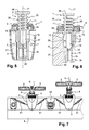
figure 5 est une vue en coupe selon 5-5 de lafigure 4 ; - la
figure 6 est une vue en coupe selon 6-6 de lafigure 3 (sans l'embout support de latte) ; - la
figure 7 est une vue de face d'une variante de réalisation du dispositif de réglage conforme à l'invention.
- the
figure 1 is a perspective view of an adjusting device according to the invention, in position on a frame, for example a bed frame spar; - the
figure 2 is an exploded view of the adjustment device illustrated on thefigure 1 ; - the
figure 3 is a front view of the adjustment device ofFigures 1 and 2 , equipped with a batten support tip, shown in dotted lines; - the
figure 4 is a side view of the adjustment device illustrated on theFigures 1 to 3 ; - the
figure 5 is a sectional view along 5-5 of thefigure 4 ; - the
figure 6 is a sectional view along 6-6 of thefigure 3 (without the batten support tip); - the
figure 7 is a front view of an alternative embodiment of the adjustment device according to the invention.
Tel que représenté sur les
D'une manière générale, la tige 4 est maintenue et guidée en translation verticale dans l'embase 2 et sa manoeuvre en translation, vers le haut ou vers le bas, est réalisée par la molette-écrou 3 avec laquelle elle coopère par l'intermédiaire de filetages adaptés, de manière à régler le niveau vertical de son extrémité supérieure qui porte un élément support 5 tel qu'une latte ou un plateau, soit directement, soit par l'intermédiaire d'un organe de maintien 6 tel qu'un embout de latte (illustré en pointillés sur la
L'embase 2 consiste en une pièce en matière plastique munie ici de deux orifices 7 qui permettent sa fixation sur un châssis support 8, par exemple sur la face interne verticale d'un longeron de sommier.The
Cette embase 2 comporte un logement supérieur 9 pour la réception de la molette-écrou 3, et un logement inférieur 10 en particulier pour la réception de la partie inférieure de la tige coulissante 4. Le logement supérieur 9 comporte une ouverture supérieure 11 et une ouverture inférieure 12 ; il comporte également des fenêtres périphériques, en particulier une fenêtre frontale 13 encadrée par deux fenêtres latérales 13'. De son côté, le logement inférieur 10 comporte une partie supérieure 15 de forme générale cylindrique, et une partie inférieure 16, également de forme générale cylindrique, qui sont co-axiales entre elles, centrées sur un axe vertical 17. Sur l'avant, la partie inférieure 16 du logement 10 comporte une ouverture frontale 18 délimitée en particulier par une bordure supérieure 19. Sur l'arrière, cette partie inférieure de logement 16 comporte un ergot saillant vertical 20, qui s'étend dans le plan vertical médian du logement 10 (parallèlement à l'axe 17) et qui est réalisé monobloc avec une platine arrière 21. Cette platine arrière 21 est conformée pour venir se plaquer contre la face verticale du longeron de sommier 8 et elle comporte, sur ses côtés, les deux orifices de fixation 7 précités.This
La molette-écrou 3 consiste en une pièce plastique en forme générale de couronne circulaire, dont la périphérie est munie de striures 22 destinées à faciliter sa manoeuvre en rotation. Son orifice central 23 comporte un filetage 24.The wheel-
La tige de réglage 4 consiste en une pièce en matière plastique de forme générale cylindrique. Elle comporte une partie supérieure 25 équipée d'un filetage 26 complémentaire du filetage 24 de la molette-écrou 3, et une partie inférieure 27 dépourvue de filetage.
Son extrémité supérieure est équipée de moyens 28 (ici en forme de simple plateau), qui permettent la réception amovible d'un organe de maintien 6 de l'élément support 5, par exemple, comme illustré sur la
Its upper end is equipped with means 28 (here in the form of a simple plate), which allow the removable reception of a
La partie inférieure 27 de la tige de réglage 4 comporte une rainure longitudinale arrière 29 (visible sur la
A son extrémité inférieure, la partie inférieure de tige 27 comporte, sur l'avant, une languette élastique 30 destinée à coopérer avec la bordure supérieure 19 précitée de l'ouverture frontale 18 réalisée dans le logement inférieur 10 de l'embase, pour former un élément de butée (butée haute) limitant l'extension verticale de la tige 4.At its lower end, the lower portion of
Le dispositif de réglage 1 est monté en positionnant la molette-écrou 3 dans son logement de réception 9, avec son orifice central 23 placé en regard des ouvertures supérieure 11 et inférieure 12, l'axe dudit orifice 23 étant centré sur l'axe 17 du logement inférieur 10 de l'embase 2.
Une partie de la périphérie de la molette-écrou 3 est alors rendue manoeuvrable par les fenêtres frontales 13 ou latérales 13'.
Ensuite, la tige de réglage 4 est insérée par son extrémité inférieure au sein de l'embase 2, en passant au travers de l'orifice 23 de la molette-écrou 3, jusqu'à ce que son filetage supérieur 26 coopère avec le filetage 24 de ladite molette-écrou 3. Alors, la molette-écrou 3 est manoeuvrée en rotation pour initier la coopération entre les filetages 24 et 26 et pour assurer un positionnement correct de la partie inférieure de la tige 4 au sein de son logement de réception 16.
Lors de cette opération, la languette 30 passe élastiquement le niveau de la bordure supérieure 19 de l'ouverture 18 pour se retrouver légèrement en saillie vers l'extérieur ; d'autre part, la rainure arrière 29 de la tige 4 vient s'engager sur l'ergot saillant 20 de l'embase 2.The adjusting
Part of the periphery of the wheel-
Then, the
During this operation, the
De la sorte, la tête 28 de la tige de réglage 4 fait saillie au-dessus de l'embase 2. La partie supérieure filetée 26 de cette tige 4 traverse: - l'orifice supérieur 11 du logement 9, - l'orifice central 23 de la molette-écrou 3 (avec le filetage 24 duquel elle coopère), ainsi que - l'orifice inférieur 12 du logement 9 ; et elle s'étend partiellement dans la partie supérieure 15 du logement inférieur 10 de l'embase 2.
Cette partie de logement 15 est structurée en fonction des caractéristiques dimensionnelles de la partie filetée de tige 26, pour ne pas perturber le déplacement en translation de la tige 4.
D'autre part, la partie inférieure 27 de la tige 4 s'étend, selon sa position, au moins partiellement dans la partie inférieure 16 du logement d'embase 10. Cette partie inférieure de logement 16 présente avantageusement une forme générale cylindrique correspondant, au jeu près, aux dimensions externes de la partie inférieure de tige 27.In this way, the
This
On the other hand, the
Ce dispositif de réglage 1 est positionné sur son châssis support 8 de manière à ce que l'axe de la tige de réglage 4 s'étende verticalement ou sensiblement verticalement, cet axe étant confondu avec l'axe de rotation de la molette-écrou 3 et avec l'axe 17 du logement d'embase 10.This
On comprend bien alors, en particulier au regard des
Une partie seulement ou la totalité des éléments supports 5 (latte ou plateau) de sommier ou de siège peut être équipée de tels dispositifs de réglage.
S'il s'agit de lattes transversales, les deux extrémités de ces lattes seront supportées par de tels dispositifs.Only part or all of the support elements 5 (slat or tray) of bed base or seat can be equipped with such adjustment devices.
If it is transverse slats, the two ends of these slats will be supported by such devices.
Les lattes ou les plateaux 5 peuvent être fixés directement sur la tête de la tige coulissante 4, ou par l'intermédiaire d'organes de maintien 6 fixés de manière amovible.The slats or
Par ce type de dispositif, le réglage vertical de hauteur s'effectue très facilement et de manière très fine, du fait de la linéarité de déplacement et de l'aspect translatif de ce déplacement.By this type of device, the vertical height adjustment is very easily and very finely, because of the linearity of displacement and the translational aspect of this displacement.
La course de réglage peut être de l'ordre de quelques centimètres (1 à 5 cm par exemple). Cette course de réglage est limitée, vers le bas, par la butée de l'extrémité inférieure de la tige 4 contre le fond de l'embase 2, ou par la butée du plateau supérieur 28 contre la partie supérieure du logement 9.
Vers le haut, cette course est limitée par la languette élastique 30 venant coopérer avec la bordure supérieure 19 de l'ouverture frontale 18.
On notera que le démontage du dispositif est possible du fait des caractéristiques d'élasticité de cette languette 30.The adjustment stroke can be of the order of a few centimeters (1 to 5 cm for example). This adjustment stroke is limited, downwards, by the abutment of the lower end of the
Upwards, this stroke is limited by the
It will be noted that the disassembly of the device is possible because of the elasticity characteristics of this
On a représenté sur la
La hauteur des ensembles bi-lattes 5, 6 peut ainsi être réglée à volonté (dans la plage de réglage admissible), cela de manière très simple et très fine, par simple manoeuvre en rotation de la molette-écrou 3.
La structure interne de l'embase 2 n'apparaît pas sur la
The height of the two-
The internal structure of the
Claims (11)
Applications Claiming Priority (1)
| Application Number | Priority Date | Filing Date | Title |
|---|---|---|---|
| FR0701640A FR2913322B1 (en) | 2007-03-07 | 2007-03-07 | DEVICE FOR ADJUSTING THE VERTICAL LEVEL OF A LATTE-TYPE SUPPORTING ELEMENT OR PLATE FOR SOMMIER OR SEAT |
Publications (3)
| Publication Number | Publication Date |
|---|---|
| EP1969973A2 true EP1969973A2 (en) | 2008-09-17 |
| EP1969973A3 EP1969973A3 (en) | 2008-10-08 |
| EP1969973B1 EP1969973B1 (en) | 2010-06-16 |
Family
ID=38828589
Family Applications (1)
| Application Number | Title | Priority Date | Filing Date |
|---|---|---|---|
| EP20080305051 Expired - Fee Related EP1969973B1 (en) | 2007-03-07 | 2008-03-07 | Device for adjusting the vertical level of a support element such as a slat or a beam of a bed base or a chair |
Country Status (3)
| Country | Link |
|---|---|
| EP (1) | EP1969973B1 (en) |
| DE (1) | DE602008001516D1 (en) |
| FR (1) | FR2913322B1 (en) |
Cited By (3)
| Publication number | Priority date | Publication date | Assignee | Title |
|---|---|---|---|---|
| EP2090196A3 (en) * | 2008-02-14 | 2009-10-21 | Diemer & Dr. Jaspert GbR | Spring element for a spring core mattress or an under mattress or edge holder for a slated frame |
| US20110258772A1 (en) * | 2008-09-30 | 2011-10-27 | Frank Verschuere | Bed system |
| EP2392232A1 (en) * | 2010-06-03 | 2011-12-07 | Delahousse Et Fils | Seating or bedding device for the frame of a bed base or chair |
Families Citing this family (1)
| Publication number | Priority date | Publication date | Assignee | Title |
|---|---|---|---|---|
| DE202010009239U1 (en) | 2010-06-18 | 2010-10-07 | Woeste, Peter, Dipl.-Kaufm. Dipl.-Designer | Support device for lying and sitting elements |
Citations (3)
| Publication number | Priority date | Publication date | Assignee | Title |
|---|---|---|---|---|
| EP0200900A2 (en) * | 1985-03-26 | 1986-11-12 | Metzeler Schaum Gmbh | Elastic support for the slats of a slatted support base |
| DE9107386U1 (en) * | 1991-06-14 | 1991-12-05 | Dunlop Gmbh, 6450 Hanau, De | |
| DE9301114U1 (en) * | 1993-01-27 | 1993-04-08 | Metzeler Schaum Gmbh, 8940 Memmingen, De |
-
2007
- 2007-03-07 FR FR0701640A patent/FR2913322B1/en not_active Expired - Fee Related
-
2008
- 2008-03-07 DE DE200860001516 patent/DE602008001516D1/en active Active
- 2008-03-07 EP EP20080305051 patent/EP1969973B1/en not_active Expired - Fee Related
Patent Citations (3)
| Publication number | Priority date | Publication date | Assignee | Title |
|---|---|---|---|---|
| EP0200900A2 (en) * | 1985-03-26 | 1986-11-12 | Metzeler Schaum Gmbh | Elastic support for the slats of a slatted support base |
| DE9107386U1 (en) * | 1991-06-14 | 1991-12-05 | Dunlop Gmbh, 6450 Hanau, De | |
| DE9301114U1 (en) * | 1993-01-27 | 1993-04-08 | Metzeler Schaum Gmbh, 8940 Memmingen, De |
Cited By (5)
| Publication number | Priority date | Publication date | Assignee | Title |
|---|---|---|---|---|
| EP2090196A3 (en) * | 2008-02-14 | 2009-10-21 | Diemer & Dr. Jaspert GbR | Spring element for a spring core mattress or an under mattress or edge holder for a slated frame |
| US20110258772A1 (en) * | 2008-09-30 | 2011-10-27 | Frank Verschuere | Bed system |
| US8918928B2 (en) * | 2008-09-30 | 2014-12-30 | Ls Bedding | Adjustable bed system |
| EP2392232A1 (en) * | 2010-06-03 | 2011-12-07 | Delahousse Et Fils | Seating or bedding device for the frame of a bed base or chair |
| FR2960754A1 (en) * | 2010-06-03 | 2011-12-09 | Delahousse Et Fils Sa | SEATING OR SLEEPING DEVICE FOR SOMMIER CHASSIS OR SEAT |
Also Published As
| Publication number | Publication date |
|---|---|
| DE602008001516D1 (en) | 2010-07-29 |
| EP1969973A3 (en) | 2008-10-08 |
| FR2913322B1 (en) | 2009-06-05 |
| EP1969973B1 (en) | 2010-06-16 |
| FR2913322A1 (en) | 2008-09-12 |
Similar Documents
| Publication | Publication Date | Title |
|---|---|---|
| FR2568528A1 (en) | ADJUSTABLE HEADREST FOR AUTOMOBILE OR THE LIKE | |
| EP2878481B1 (en) | Passenger seat with bucket structure and adjustable position | |
| EP1969973B1 (en) | Device for adjusting the vertical level of a support element such as a slat or a beam of a bed base or a chair | |
| EP0816163B1 (en) | Infant seat with movable armrests | |
| FR3065407A1 (en) | ARMREST ARMREST MODULE FOR MOTOR VEHICLE SEAT | |
| EP2030531B1 (en) | Hanging device for mattress support and bed frame equipped with such a device | |
| EP0458000B1 (en) | Vehicle seat | |
| FR2670101A1 (en) | Improvement to devices for the suspension and guidance of slats for a mattress support and mattress support provided with such a device | |
| FR2981309A1 (en) | PASSENGER SEAT FOR A RAIL TRANSPORT VEHICLE HAVING A DEVICE FOR ADJUSTING THE LUMBAR SUPPORT | |
| FR2666973A1 (en) | Slide (cursor) for varying the tension, for a slatted bed base | |
| EP2151178B1 (en) | Device for adjusting the height of the supporting means of a seat or a mattress in relation to a frame | |
| EP2965665A1 (en) | Suspension device with slats for bed base or seat | |
| JP2008012313A (en) | Device for fixing caster mounting unit to frame portion of wheel chair, eccentric body, and wheelchair | |
| EP3071072A1 (en) | Office chair having synchronized backrest and seat movements | |
| WO2007028891A2 (en) | Motor vehicle child safety seat | |
| FR2915068A1 (en) | DEVICE FOR ADJUSTING THE FLEXIBILITY OF THE LATTE (S) OF A SOMMIER WITH A LATTE (S) AND SOMMIER EQUIPPED WITH SUCH A DEVICE. | |
| FR2773760A1 (en) | CHILD STROLLER, WITH EXTENDABLE TELESCOPIC HAMMOCK, AND CORRESPONDING HAMMOCK | |
| EP1266594A1 (en) | Table with built-in retractable seats | |
| EP1836934B1 (en) | Suspension element for bed base or seat of the type with slats equipped with firmness-adjustment means | |
| WO2016185109A1 (en) | Saddle having a longitudinally and vertically adjustable backrest for narrow motor vehicle | |
| EP0281445A1 (en) | Adjustable and tiltable seat, particularly for a vehicle | |
| FR2883144A1 (en) | Bed spring supporting crosspiece`s height adjustment device for bed frame, has part with superposed slots at fixed state of device to stringers, where slots have edges constituting pins for supporting ends of crosspieces | |
| FR2484807A1 (en) | adjustment for vehicle seat - consists of two side support girders and two coaxial pinions | |
| FR2745245A1 (en) | Adjustable head rest for vehicle seats | |
| FR3058948A1 (en) | SUSPENSION DEVICE FOR THE SEAT OF A MOTOR VEHICLE. |
Legal Events
| Date | Code | Title | Description |
|---|---|---|---|
| PUAI | Public reference made under article 153(3) epc to a published international application that has entered the european phase |
Free format text: ORIGINAL CODE: 0009012 |
|
| PUAL | Search report despatched |
Free format text: ORIGINAL CODE: 0009013 |
|
| AK | Designated contracting states |
Kind code of ref document: A2 Designated state(s): AT BE BG CH CY CZ DE DK EE ES FI FR GB GR HR HU IE IS IT LI LT LU LV MC MT NL NO PL PT RO SE SI SK TR |
|
| AX | Request for extension of the european patent |
Extension state: AL BA MK RS |
|
| AK | Designated contracting states |
Kind code of ref document: A3 Designated state(s): AT BE BG CH CY CZ DE DK EE ES FI FR GB GR HR HU IE IS IT LI LT LU LV MC MT NL NO PL PT RO SE SI SK TR |
|
| AX | Request for extension of the european patent |
Extension state: AL BA MK RS |
|
| 17P | Request for examination filed |
Effective date: 20090407 |
|
| AKX | Designation fees paid |
Designated state(s): BE DE FR |
|
| GRAP | Despatch of communication of intention to grant a patent |
Free format text: ORIGINAL CODE: EPIDOSNIGR1 |
|
| GRAS | Grant fee paid |
Free format text: ORIGINAL CODE: EPIDOSNIGR3 |
|
| GRAA | (expected) grant |
Free format text: ORIGINAL CODE: 0009210 |
|
| AK | Designated contracting states |
Kind code of ref document: B1 Designated state(s): BE DE FR |
|
| REF | Corresponds to: |
Ref document number: 602008001516 Country of ref document: DE Date of ref document: 20100729 Kind code of ref document: P |
|
| PLBE | No opposition filed within time limit |
Free format text: ORIGINAL CODE: 0009261 |
|
| STAA | Information on the status of an ep patent application or granted ep patent |
Free format text: STATUS: NO OPPOSITION FILED WITHIN TIME LIMIT |
|
| 26N | No opposition filed |
Effective date: 20110317 |
|
| REG | Reference to a national code |
Ref country code: DE Ref legal event code: R097 Ref document number: 602008001516 Country of ref document: DE Effective date: 20110316 |
|
| PGFP | Annual fee paid to national office [announced via postgrant information from national office to epo] |
Ref country code: FR Payment date: 20131203 Year of fee payment: 7 |
|
| PGFP | Annual fee paid to national office [announced via postgrant information from national office to epo] |
Ref country code: BE Payment date: 20131205 Year of fee payment: 7 |
|
| PGFP | Annual fee paid to national office [announced via postgrant information from national office to epo] |
Ref country code: DE Payment date: 20131205 Year of fee payment: 7 |
|
| REG | Reference to a national code |
Ref country code: DE Ref legal event code: R119 Ref document number: 602008001516 Country of ref document: DE |
|
| REG | Reference to a national code |
Ref country code: FR Ref legal event code: ST Effective date: 20151130 |
|
| PG25 | Lapsed in a contracting state [announced via postgrant information from national office to epo] |
Ref country code: DE Free format text: LAPSE BECAUSE OF NON-PAYMENT OF DUE FEES Effective date: 20151001 |
|
| PG25 | Lapsed in a contracting state [announced via postgrant information from national office to epo] |
Ref country code: FR Free format text: LAPSE BECAUSE OF NON-PAYMENT OF DUE FEES Effective date: 20150331 |
|
| PG25 | Lapsed in a contracting state [announced via postgrant information from national office to epo] |
Ref country code: BE Free format text: LAPSE BECAUSE OF NON-PAYMENT OF DUE FEES Effective date: 20150331 |