EP1969875B2 - Airborne onboard base transceiver station for mobile communication - Google Patents
Airborne onboard base transceiver station for mobile communication Download PDFInfo
- Publication number
- EP1969875B2 EP1969875B2 EP05823688.6A EP05823688A EP1969875B2 EP 1969875 B2 EP1969875 B2 EP 1969875B2 EP 05823688 A EP05823688 A EP 05823688A EP 1969875 B2 EP1969875 B2 EP 1969875B2
- Authority
- EP
- European Patent Office
- Prior art keywords
- signal
- onboard
- bts
- screening device
- base station
- Prior art date
- Legal status (The legal status is an assumption and is not a legal conclusion. Google has not performed a legal analysis and makes no representation as to the accuracy of the status listed.)
- Active
Links
- 238000010295 mobile communication Methods 0.000 title description 7
- 238000012216 screening Methods 0.000 claims abstract description 54
- 238000004891 communication Methods 0.000 claims abstract description 35
- 238000000034 method Methods 0.000 claims abstract description 13
- 230000010267 cellular communication Effects 0.000 claims abstract description 6
- 230000000694 effects Effects 0.000 claims description 31
- 230000008901 benefit Effects 0.000 description 10
- 230000001413 cellular effect Effects 0.000 description 9
- 230000005540 biological transmission Effects 0.000 description 8
- 230000007423 decrease Effects 0.000 description 5
- IRLPACMLTUPBCL-KQYNXXCUSA-N 5'-adenylyl sulfate Chemical compound C1=NC=2C(N)=NC=NC=2N1[C@@H]1O[C@H](COP(O)(=O)OS(O)(=O)=O)[C@@H](O)[C@H]1O IRLPACMLTUPBCL-KQYNXXCUSA-N 0.000 description 4
- 230000000977 initiatory effect Effects 0.000 description 4
- 230000001419 dependent effect Effects 0.000 description 3
- 238000001514 detection method Methods 0.000 description 3
- 238000012937 correction Methods 0.000 description 2
- 238000010586 diagram Methods 0.000 description 2
- 230000003993 interaction Effects 0.000 description 2
- 230000001360 synchronised effect Effects 0.000 description 2
- 230000002730 additional effect Effects 0.000 description 1
- 238000004458 analytical method Methods 0.000 description 1
- 230000002238 attenuated effect Effects 0.000 description 1
- 238000010276 construction Methods 0.000 description 1
- 230000008878 coupling Effects 0.000 description 1
- 238000010168 coupling process Methods 0.000 description 1
- 238000005859 coupling reaction Methods 0.000 description 1
- 230000003247 decreasing effect Effects 0.000 description 1
- 230000002452 interceptive effect Effects 0.000 description 1
- 230000000670 limiting effect Effects 0.000 description 1
- 230000000149 penetrating effect Effects 0.000 description 1
- 230000002829 reductive effect Effects 0.000 description 1
- 238000000926 separation method Methods 0.000 description 1
- 230000011664 signaling Effects 0.000 description 1
- 238000001228 spectrum Methods 0.000 description 1
- 230000002459 sustained effect Effects 0.000 description 1
- 238000012360 testing method Methods 0.000 description 1
- 238000012549 training Methods 0.000 description 1
- 238000012546 transfer Methods 0.000 description 1
- 239000002699 waste material Substances 0.000 description 1
Images


Classifications
-
- H—ELECTRICITY
- H04—ELECTRIC COMMUNICATION TECHNIQUE
- H04K—SECRET COMMUNICATION; JAMMING OF COMMUNICATION
- H04K3/00—Jamming of communication; Counter-measures
- H04K3/60—Jamming involving special techniques
- H04K3/65—Jamming involving special techniques using deceptive jamming or spoofing, e.g. transmission of false signals for premature triggering of RCIED, for forced connection or disconnection to/from a network or for generation of dummy target signal
-
- H—ELECTRICITY
- H04—ELECTRIC COMMUNICATION TECHNIQUE
- H04B—TRANSMISSION
- H04B7/00—Radio transmission systems, i.e. using radiation field
- H04B7/14—Relay systems
- H04B7/15—Active relay systems
- H04B7/185—Space-based or airborne stations; Stations for satellite systems
- H04B7/18502—Airborne stations
- H04B7/18506—Communications with or from aircraft, i.e. aeronautical mobile service
-
- H—ELECTRICITY
- H04—ELECTRIC COMMUNICATION TECHNIQUE
- H04K—SECRET COMMUNICATION; JAMMING OF COMMUNICATION
- H04K3/00—Jamming of communication; Counter-measures
- H04K3/40—Jamming having variable characteristics
- H04K3/45—Jamming having variable characteristics characterized by including monitoring of the target or target signal, e.g. in reactive jammers or follower jammers for example by means of an alternation of jamming phases and monitoring phases, called "look-through mode"
-
- H—ELECTRICITY
- H04—ELECTRIC COMMUNICATION TECHNIQUE
- H04K—SECRET COMMUNICATION; JAMMING OF COMMUNICATION
- H04K3/00—Jamming of communication; Counter-measures
- H04K3/80—Jamming or countermeasure characterized by its function
- H04K3/84—Jamming or countermeasure characterized by its function related to preventing electromagnetic interference in petrol station, hospital, plane or cinema
-
- H—ELECTRICITY
- H04—ELECTRIC COMMUNICATION TECHNIQUE
- H04W—WIRELESS COMMUNICATION NETWORKS
- H04W48/00—Access restriction; Network selection; Access point selection
- H04W48/02—Access restriction performed under specific conditions
-
- H—ELECTRICITY
- H04—ELECTRIC COMMUNICATION TECHNIQUE
- H04K—SECRET COMMUNICATION; JAMMING OF COMMUNICATION
- H04K2203/00—Jamming of communication; Countermeasures
- H04K2203/10—Jamming or countermeasure used for a particular application
- H04K2203/16—Jamming or countermeasure used for a particular application for telephony
-
- H—ELECTRICITY
- H04—ELECTRIC COMMUNICATION TECHNIQUE
- H04K—SECRET COMMUNICATION; JAMMING OF COMMUNICATION
- H04K2203/00—Jamming of communication; Countermeasures
- H04K2203/10—Jamming or countermeasure used for a particular application
- H04K2203/22—Jamming or countermeasure used for a particular application for communication related to vehicles
-
- H—ELECTRICITY
- H04—ELECTRIC COMMUNICATION TECHNIQUE
- H04K—SECRET COMMUNICATION; JAMMING OF COMMUNICATION
- H04K3/00—Jamming of communication; Counter-measures
- H04K3/40—Jamming having variable characteristics
- H04K3/42—Jamming having variable characteristics characterized by the control of the jamming frequency or wavelength
-
- H—ELECTRICITY
- H04—ELECTRIC COMMUNICATION TECHNIQUE
- H04K—SECRET COMMUNICATION; JAMMING OF COMMUNICATION
- H04K3/00—Jamming of communication; Counter-measures
- H04K3/40—Jamming having variable characteristics
- H04K3/43—Jamming having variable characteristics characterized by the control of the jamming power, signal-to-noise ratio or geographic coverage area
Definitions
- the invention refers to a base station, BTS, and a method for a BTS, for a cellular communication system comprising a user equipment, UE, onboard an aircraft being at a predetermined altitude, and a terrestrial network.
- the UE has an omni directional antenna sending out signals in a spherical pattern to a terrestrial network.
- the terrestrial network is built up from a number of cells managed by a number of base stations connected to ground antennas covering each cell.
- the ground antennas are normally not omni directional, but restricted to an azimuth angle giving a horizontal sector and an altitude angle giving a vertical sector.
- the UEs communicate with that base station having the best communication parameters for the moment.
- the communication parameters are altered for the worse, for example when the UE moves away from the base station and migrates to another cell, the UE moves from the weaker base station to a neighbouring base station with better communication parameters.
- First generation (1G) systems such as NMT, AMPS, etc.
- second generation (2G) system such as GSM
- the reason for using different frequencies and codes respectively is to minimise interference problems for UEs in neighbouring cells.
- a problem occurs when the plane is at a distance from the ground because the line of sight from above is so wide that a signal from the UE engages/interferes with a number of cells using the same frequency. For example, if a person onboard an aircraft at an altitude above 3000m turns on his cellular phone, the omni directional antenna will send in at least the direction of sight and will thus finally engage/interfere with a number of different cells using the same frequency or code. This causes the above mentioned problem with interference for a number of UEs in the terrestrial network and may therefore out voice utilized frequency/timeslot combinations in a large region of the network, also at distances far outside the normal GSM cell radius.
- DE19920153C2 discloses an onboard base station preventing mobiles from connecting to external networks.
- the invention refers to a method for a base station (hereinafter called BTS) for a cellular communication system comprising a user equipment, UE, onboard an aircraft being at a predetermined altitude and a terrestrial network, characterized in that method comprises the following steps:
- matched refers to the first signal having a first effect in a first frequency band being matched to screen the second signal having a second effect in a second frequency band.
- the first frequency band is equal to or greater than the second frequency band.
- the third signal has a third effect and a third frequency band being at least partly or completely within the first frequency band of the first signal.
- the communication link is established because the third effect of the third signal is greater than the first effect and/or because the third effect being greater than the second effect.
- the invention also refers to a method for a communication system.
- the first signal screens the second signal so that the UE cannot establish a communication link directly to the terrestrial network.
- the UE cannot therefore home in on a certain frequency within the frequency band of the second signal.
- the onboard BTS according to the invention thus provides a fine instrument to locally control the traffic transmission channels without inter-working with all networks in the potentially affected terrestrial region.
- the fourth signal is the normal signal being generated in the UE.
- the invention according to the first embodiment may be used in all existing terrestrial networks such as AMPS/D-AMPS, GSM, cdma/CDMA 2000 and UMTS, i.e. all existing 1 G, 2G, 3G, 3,5 and possibly also future 4G systems. All frequency channels at these bands are screened to force the UE to move to a dedicated band with allowed access channels supported by the onboard BTS.
- the dedicated band may be a narrow band within the screened band or a different band.
- the onboard BTS may comprise a signal detection device that detects the second signal from the terrestrial network. The information is utilized by the onboard device when determining the signal strength and frequency of the first signal.
- the onboard BTS may lack a detection device, but may instead be programmed for certain events, i.e. the first signal has a signal strength and frequency already set for different events. The onboard BTS may then be controlled to use different modes dependent on the event at hand. The onboard BTS may be controlled both manually and automatically.
- the third signal has a predetermined effect in a predetermined frequency band when leaving the onboard BTS so that the ratio between the third signal and the second signal and or the third signal and the first signal corresponds at least to the minimum requirement for signal to noise ratio (s/n) accepted by the UE in order to establish a communication link.
- s/n signal to noise ratio
- the first signal covers the entire frequency spectrum used by the terrestrial network.
- This may be implemented by the onboard BTS sending out the first signal in the form of a pulsed signal with a repetition interval being short enough to generate a number of pulses for all frequency channels within one time slot.
- the accumulated pulses within one time slot have enough energy to screen the second signal such that the signal to noise ratio becomes too low in order to establish a communication link.
- the screening device may send out a continuous signal covering all frequency channels used by the terrestrial system.
- the invention is intended to be used during the following scenario.
- UEs such as mobile phones and computers comprising communication equipment.
- the screening device When the aircraft is airborne at a certain altitude, the screening device is turned on and the onboard passengers are allowed to turn their UEs on.
- the UEs When the UEs are turned on, the screening device has generated the first signal screening all signals (the second signal) from the terrestrial network thereby disturbing the UEs reception of the terrestrial second signal necessary to make/initiate direct contact with the terrestrial network.
- the signal generator generates the third signal being stronger than the first signal (and/or the second signal) and at a certain frequency or frequencies.
- the UEs are searching for a signal with acceptable signal to noise ratio and homes in on the third signal.
- the onboard BTS thus creates an onboard cell in which the UEs may be used.
- the system is preferably arranged so that the crew can start the screening device without the onboard BTS signal generator being active. This causes the possibility to block all UEs from being able to communicate.
- the signal generator may then independently be switched on and switched off when traffic is to be allowed or prohibited respectively.
- the onboard BTS is preferably connected to an onboard antenna in the form of a leaky cable extending in the longitudinal direction of the aircraft and in the vicinity of a passenger using a UE. This short distance between the UE and the antenna gives the possibility to keep the power of the first and third signals at a minimum.
- the onboard BTS is connected to a satellite link handling traffic between the aircraft and dedicated base stations in the terrestrial network.
- the onboard BTS thereby mediates traffic between the terrestrial network and the UEs via the satellite link.
- the satellite link comprises an onboard satellite antenna sending signals to a satellite positioned at a higher level than the aircraft.
- the satellite communicates with the dedicated bases station.
- the satellite link may comprise a modem between the onboard BTS and the satellite.
- the communication between the onboard BTS and the modem may be based on A-bis (Interface between BSC and BTS in GSM) or IP (Internet protocol).
- the satellite link may be exchanged to a link between an onboard antenna directed to the ground communicating with a dedicated base station or base stations.
- the GSM frequencies are evenly distributed over the GSM 900, GSM 1800 and over the GSM 1900 bands.
- a cell normally uses between 2 and 12 different frequencies.
- the second signal When the aircraft is at an altitude of 3000m the second signal has lost approximately 107dB because of the transport through the air and 10 dB because of the signal penetrating the wall of the aircraft. Additional losses are caused by the vertical antenna gain of the terrestrial BTS.
- the signal strength in the aircraft of the received second signal from the terrestrial network is about -95dBm after the above mentioned losses.
- the signal strength of the first signal is set to +15dB above the received terrestrial second signal strength and the third signal is defined to a signal strength of additionally +15dB, i.e. approximately 30dB margin to the second signal.
- the screening device generates the first signal comprising all the necessary frequencies and with an effect of about 3 dBm per 200KHz when entering the antenna system.
- the third signal may have an initial effect of up to 35W/45dBm when entering the antenna system coupled to the onboard BTS. For the case with 15 dB margin to the first signal it is sufficient with an initial effect of 18 dBm when entering the antenna system.
- the UE has a threshold for the signal to noise ratio (s/n) of at least 7 dB in order to establish a communication link with the onboard BTS.
- the third signal has an effect of at least 18dBm. The effect is dependent on frequency and bandwidth.
- the first signal could have a signal strength being less than the signal strength of the second signal, namely down to 7 dB but not below the second signal strength, for example 6.5 dB below the second signal.
- the third signal must then add at least 7 dB to the second signal in the aircraft.
- suitable levels of the first signal have been shown to be between 0 to 12 dBm when entering the antenna, dependent on the type of aircraft construction due to the fact that, the larger the aircraft the longer the antenna and the greater the losses.
- the UE cannot transmit a signal below 0 dBm why this level is the starting point for received signal in the terrestrial network from the UE.
- the example discusses a worst case estimate of the interference level at the onboard BTS and the terrestrial system using GSM 1800 and isotropic antennas.
- a terrestrial BTS transmits normally at 30 dBm (1W) to 60 dBm in the horizontal plane.
- the resulting energy level at distance of 3 km has been measured to -85 dBm.
- the aircraft chassis adds another 10 dB of shielding, resulting in a -95 dBm signal level from the terrestrial BTS inside the cabin.
- the screening device will be configured to exceed this level with about 15 dB, i.e. the onboard UE shall perceive a first signal level of -80 dBm.
- the required effect of the first signal from the onboard BTS per frequency channel fed into the leaky antenna cable are calculated by compensating for the antenna coupling Loss (73 dB for one antenna) and the antenna cable alternation (4 dB) resulting in -3 dBm. This effect, being the worst case, is reduced by 10 dB due to shielding of the chassis and the free space loss lost in traversing to ground (107 dB) and the results is -120 dBm impact on the terrestrial network from the screening device.
- the onboard BTS will transmit the third signal at a level that is received by the UE at an additional 15 dB above the first signal, i.e. -65 dBm. Similar to the screening device ground impact calculation above the impact at ground from the third signal equals -105 dBm.
- the onboard BTS will be configured to limit the UE to its minimum signal level, i.e. 0 dBm.
- This configuration is done in a BSC in a terrestrial system and is fed to the UE in the third signal.
- the BSC communicates with the onboard BTS via a dedicated route, for example, a satellite communication link.
- the BSC may be placed in any location suitable for the purpose of managing one or a number of onboard BTS in the air.
- the total effect required by the screening device and the signal generator may also be concluded from the above. First the losses in antenna near components (6 dB) have to be taken in account.
- the resulting screening device (first signal) and signal generator (third signal) output power are 3 respective 18 dBm per frequency channel.
- the screening device will transmit on the full GSM 900 and GSM 1800 bands (124 + 375) 499 frequency channels adding (10xLog499) 27.0 dB resulting in 30 dBm total screening device output power in the first signal.
- the signal generator in the onboard BTS will only transmit at three or less frequency channels (4.8 dB) resulting in 22.8 dBm onboard BTS output power of the third signal.
- the signal generator may generate a third signal comprising more frequency channels than three and the BTS output power must then be enhanced accordingly.
- the first signal does not cover the entire frequency band corresponding to the second signal, but only a part of the frequency band.
- the screening device is arranged to generate a pulsed first signal being matched to screen a control channel in the second signal in the cellular network.
- screen refers to the first signal being transmitted in the same region where the second signal is transmitted such that the first signal is superposed onto at least that part of the second signal comprising the control channel thereby disturbing the information in the control channel. If the information is disturbed the UE cannot read the information and cannot therefore establish a connection.
- match refers to the screening device being fed information on the second signal in the form of duration, effect, repetition interval and position of the control channel in the second signal, and from that information calculating and generating the pulsed first signal with a suitable pulse interval and repetition interval and effect so that the pulsed first signal disturbs the second signal during that time period the control channel is transmitted in the network.
- One benefit of the embodiment is that only a part of the second signal needs to be blocked in order to prevent the UE to establish a connection with the network. Therefore the screening device does not have to be used continuously. On the contrary the screening device generates the first signal in the form of one pulse with a predetermined pulse interval and at a predetermined repetition interval. The predetermined pulse interval and the predetermined repetition interval shall be set such that the control channel is blocked. The screening device thus uses only a fraction of the duration of the second signal. The benefit of this embodiment thus lies in the screening device being less power consuming and may, for the same power usage, thus be utilised at a higher degree than a continuous screening device by generating a number of different pulses for screening of additional signals from the network.
- the pulsed first signal has a first effect in a first frequency band utilised by the UE and the network.
- the first effect in the first signal is matched to screen the control channel in the second signal.
- a frequency band is divided, using a FDMA scheme, into a number of carrier frequencies with 25-30khZ bandwidth being spaced one from each other by a 200 khz frequency band measured from the apex of the 25-30 KHz bandwidth.
- Each carrier frequency is then divided in time using a TDMA scheme.
- This scheme splits the radio channel into 8 time slots.
- a time slot is the unit of time in a TDMA system, and it lasts approximately 0.577 ms.
- a TDMA frame is formed with 8 time slots and lasts, consequently, 4.616 ms.
- Each of the eight time slots, that form a TDMA frame are then assigned to a single user.
- Each TDMA designates one time slot to a control channel in the form of a BCH and designates the rest of the time slots to traffic channels TCH and control channels in the form of CCCH and/or DCCH. It is only the BCH that needs to be disturbed in order to prevent traffic.
- the BCH burst length is also referred to as a BCH batch.
- BCHs are used, by the BTS (here a transceiver), to provide the UE with the sufficient information it needs to synchronize with the network.
- the BCH burst length extends over 5 and 1/8 TDMA frames and consequently 23.657 ms long
- the BCH burst length is also referred to as a BCH batch.
- Three different types of BCHs can be distinguished:
- the screening device since the screening device is not necessarily time synchronized with the network, the first signal needs a theoretical minimum pulse interval of 4.616 ms (eight Time Slots) in order to secure screening of one full, or parts of two, BCH Time Slots. With BCH burst length that equals 23.657 ms the screening device must transmit periodically with a period time not exceeding 23.5 ms to secure not to risk any BCH batch to pass through intact.
- the screening device can utilize the silent time of the duty cycle to screen additional frequency channels and thereby increase the screening capability of the screening device by a factor about three compared to continuous screening.
- a further advantage is that the screening device can use 70% additional effect compared to the continuous screening or, for the same effect as the continuous signal, use 70% less power and thus giving 70% additional useful life when running on battery.
- One additional advantage is that the 70% power saving gives the possibility to increase the output signal three times with the same useful life as a continuously operated screening device.
- Another advantage of the embodiment is that the source of the screening device will also be more difficult to track and locate due to the intermittent signalling.
- One effect of the invention is that the first signal screens the second signal so that the UE cannot establish a communication link and cannot therefore home in on a certain frequency within the frequency band of the second signal.
- the 2G GSM frequencies are evenly distributed over the GSM-1800 and over the GSM-1900 bands.
- a cell normally uses between 2 and 12 different frequencies.
- the invention is not limited to a GSM based system, but may be used on different systems using a second signal with a BCH batch (BCH burst length) different number of time slots with different duration and different number of control channels.
- BCH batch BCH burst length
- the invention must then be adapted by altering the pulse interval and the pulse repetition interval in the first signal accordingly.
- the screening device may be used in a CDMA (Code Division Multiple Access) system using codes to identify connections.
- the screening device must here be matched to generate a first signal with a pulse length and repetition interval matching the corresponding control channel.
- the first signal is matched to disturb the pilot signal and may comprise a code.
- the pilot signal in a CDMA based system corresponds to the BCH batch in the TDMA based GSM system.
- the BCH batch may be in a different form than the above stated, and the control channel in such a signal is disturbed with a pulsed signal.
- the screening device is arranged to generate the pulsed first signal with a pulse length being of the same length or at least of the same length as the pulse length of the control channel and with a repetition interval less than the BCH batch for the communication system in question.
- the screening device is arranged to generate the pulsed first signal with a pulse length being of the same length or at least of the same length as the pulse length of the control channel and with a repetition interval identical to the repetition interval of at least one control channel within a broadcast channel burst length.
- the screening device may be comprised in a BTS transmitting the second signal, i.e. in a terrestrial network.
- the communication between the UE and the BTS may be controlled by the screening device without any changes being made in the second signal.
- the screening device comprises a detection device that detects and analyses the second signal.
- the onboard BTS uses the information in order to match the first signal to screen the second signal and to give the third signal such configuration that the UE can distinguish the third signal from the first and second signals.
- the third signal may comprise information intended for the control of the UE.
- information is maximum transfer unit that limits the output effect of the UE and maximum timing advance (TA) giving the UE information on how large the cell logically is.
- TA timing advance
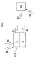
- FIG. 1 schematically shows a base station BTS (hereinafter called BTS) according to the invention onboard an aircraft 1 at an altitude overlooking a part of a terrestrial network comprising cells C1, C2, C3, C4, C5, C6 and C7 in a reoccurring pattern.
- the cell frequency plan is such that adjacent cells are not using the same frequencies in order to minimize disturbances from other cells using the same frequency.
- the onboard BTS comprises a screening device 2 and a signal generator 3.
- the onboard BTS is connected to a satellite link comprising a satellite antenna 4, a satellite 5 and a dedicated bases station 6 in the terrestrial network.
- Onboard the areoplane 1 is a UE comprising an omni directional antenna. In figure 1 the line of sight for the UE is shown as a cone 7. The UE may potentially communicate with all the cells C1-C7 within the cone 7.
- Figure 2 schematically shows a traffic scheme in a network comprising the onboard BTS and the UE according to figure 1 .
- the onboard BTS comprises the screening device 2 generating the first signal S1 and the signal generator 3 generating the third signal S3.
- the Terrestrial network transmits the second signal S2 being possible for the UE to receive.
- the UE also transmits a fourth signal S4 in an omni directional pattern. However, the fourth signal is not strong enough to interfere with the terrestrial network, but the communication is established between the onboard BTS and the UE via the third signal S3 and the fourth signal S4.
- the onboard BTS also transmits a fifth signal S5 intended to be linked to the terrestrial network.
- the onboard BTS also receives a sixth signal S6 from the terrestrial network.
- the fifth and sixth signals form a communication link between the onboard BTS a dedicated terrestrial BTS, and ultimately a communication link between the UEs and the terrestrial communication system.
- the BTS transmit signals by use of a transmitting unit (not shown) and receives signals by use of a receiving unit (not shown).
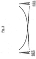
- Figure 3 schematically shows a signal to noise ratio (hereinafter called s/n) scheme between two cells operated by two terrestrially bound BTS.
- s/n signal to noise ratio
- the terrestrial network is designed to handle a certain s/n. If two adjacent GSM cells would use the same frequency there would be a region, a "dead zone", where both cells have too low s/n to operate.
- figure 3 shows that the signal strength decreases in air since the s/n decreases with distance.
- the screening device in the onboard BTS generates the first signal that increases the noise so that the s/n becomes below the threshold. Since the second signal from the terrestrial network has been decreased on its way to the aircraft, the screening device only has to generate a correspondingly weak first signal in order to decrease the s/n below the threshold.
- the weak first signal S1 does not disturb the terrestrial network because it decreases in strength on its way from the aircraft 1 to the ground so that when it reaches the base stations in the terrestrial network, the first signal S1 does not add much or no noise to the signals close to the ground.
- Figure 4 schematically shows a frequency to power diagram according to the present invention for the signals in the aircraft.
- the second signal S2 coming from the terrestrial network, comprises three frequency bands S2F1-S2F3.
- the screening device 2 in the onboard BTS generates a first signal S1 comprising three frequency bands S1F1-S1F3 corresponding to the three frequency bands S2F1-S2F3 in the second signal S2 and thus screens the second signal S2.
- Figure 4 also shows that the signal generator 3 generates a third signal S3 comprising three frequencies S3F1-S3F3 within one of the three frequency bands S1F1-S1F3.
- the third signal S3 is stronger than the first and the second signal S1, S2 thereby generating an s/n above the threshold.
- the second signal S2 has attenuated on its way from the ground and into the aircraft.
- the third signal S3 only has to be strong enough to give an s/n over the threshold in the aircraft and does not have to be as strong as the second signal S2 on the ground. Therefore, the third signal S3 does not disturb the terrestrial network because it decreases in strength on its way from the aircraft to the ground so that when it reaches the base stations in the terrestrial network the third signal does not add much or no noise to the signals close to the ground.
- the signal traffic thus becomes directed to a dedicated access point in the aircraft so that interaction with any other network is prevented.
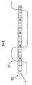
- FIG. 5 schematically shows a BCH batch 8 transmission pattern in a GSM based system.
- the transmission pattern should be read from left to right and from the top to the bottom row by row.
- the BCH batch 8 is also shown as a sequence of time slots below the transmission pattern.
- GSM is a TDMA technique with multiple frequency channels.
- Each frequency channel is divided into a TDMA frame comprising eight time slots, assigned to control channels or traffic channels (half rate or full rate TCH).
- the control channels comprise BCH, CCCH and DCCH, but it is only the BCH that needs to be disturbed.
- Each time slot is 0.577ms long and the BCH burst length is 5 and 1/8 TDMA frames and consequently 23.657 ms long.
- Each TDMA cell designates one time slot to a control channel in the form of a BCH and designates seven time slots as traffic channels TCH.
- BCH channels are used, by the BTS, to provide the UE with the sufficient information it needs to synchronize with the network.
- the BCH burst length extends over 5 and 1/8 TDMA frames and is consequently 23.657 ms long.
- the BCH burst length is also referred to as a BCH batch.
- Three different types of BCHs can be distinguished: the BCCH depicted with the letter B; the SCH depicted with the letter S, and FCCH depicted with the letter F.
- FIG. 6 schematically shows the first signal S1 from the inventive screening device superposed on the second signal S2 being a GSM transmission according to figure 5 .
- the synchronization channel S is screened by the pulsed first signal S1.
- the screening device 2 With a BCH batch 8 burst length that equals 23.657 ms the screening device 2 periodically transmits a pulse with a pulse length being at least 7 ms and with a repetition interval not exceeding 23.5 ms.
- the first signal S1 also has an effect matching the effect of the second signal such that the signal to noise ration becomes low enough for the UE to disregard the information in the control channel.
- the features of the pulsed first signal S1 hinders that any BCH batch 8 pass through intact.
- the third signal S3 is generated according to the embodiment described in connection to fig. 4 .
- the third signal is stronger than the first signal S1 and the second signal S2 and thus becomes the choice for the UE when trying to establish a communication link.
Landscapes
- Engineering & Computer Science (AREA)
- Computer Networks & Wireless Communication (AREA)
- Signal Processing (AREA)
- Physics & Mathematics (AREA)
- Health & Medical Sciences (AREA)
- Chemical & Material Sciences (AREA)
- Electromagnetism (AREA)
- Oil, Petroleum & Natural Gas (AREA)
- Public Health (AREA)
- Astronomy & Astrophysics (AREA)
- Aviation & Aerospace Engineering (AREA)
- General Physics & Mathematics (AREA)
- Computer Security & Cryptography (AREA)
- Mobile Radio Communication Systems (AREA)
- Input Circuits Of Receivers And Coupling Of Receivers And Audio Equipment (AREA)
- Transition And Organic Metals Composition Catalysts For Addition Polymerization (AREA)
- Transceivers (AREA)
Abstract
Description
-
- 1 G
- First generation wireless mobile communication network
- 2,5G
- GPRS and EDGE.
- 2G
- Second generation wireless mobile communication network
- 3G
- Third generation wireless mobile communication network
- 4G
- Fourth generation wireless mobile communication network
- AMPS
- Advanced Mobile Phone Service (1G)
- AMPS/D
- Digital Advanced Mobile Phone Service (2G)
- BCCH
- Broadcast Control Channel, one of three BCH
- BCH
- GSM Broadcast Channels, i.e. FCCH, SCH and BCCH
- BSC
- Base Station Controller
- BTS
- Base Transceiver Station
- CCCH
- Common Control CHannels
- CDMA
- Code Divisional Multiple Access
- CDMA2000
- also known as IMT-CDMA Multi-Carrier or 1xRTT (3G)
- DCCH
- Dedicated Control CHannel
- EDGE
- Enhanced Data rates for GSM Evolution (2,5G)
- FACCH
- Fast Association Control Channel
- FCCH
- Frequency Correction Channel
- GPRS
- General/GSM Packet Radio Service (2,5G)
- GSM
- Global System for Mobile communications (2G)
- IS-95
- Interim Standard 95 (IS-95), is the first CDMA-based digital cellular standard
- NMT
- Nordic Mobile Telephony (1 G)
- RBS
- Radio Base Station, the network access point in radio communication with UE served by the network.
- SACCH
- Slow Association Control CHannel
- SCH
- Synchronization Channel
- SDCCH
- Standalone Dedicated Control Channel
- TCH
- Traffic Control CHannel
- TDMA
- Time Division Multiple Access
- UE
- User Equipment, e.g. a cellular phone
- UMTS
- Universal Mobile Telecommunications System (3G)
- The invention refers to a base station, BTS, and a method for a BTS, for a cellular communication system comprising a user equipment, UE, onboard an aircraft being at a predetermined altitude, and a terrestrial network.
- In the field of mobile communication systems it is known to use mobile telephones (cellular phones) and other devices using means for wireless communication, hereinafter abbreviated UE for User Equipment. The UE has an omni directional antenna sending out signals in a spherical pattern to a terrestrial network. The terrestrial network is built up from a number of cells managed by a number of base stations connected to ground antennas covering each cell. The ground antennas are normally not omni directional, but restricted to an azimuth angle giving a horizontal sector and an altitude angle giving a vertical sector.
- The UEs communicate with that base station having the best communication parameters for the moment. When the communication parameters are altered for the worse, for example when the UE moves away from the base station and migrates to another cell, the UE moves from the weaker base station to a neighbouring base station with better communication parameters.
- Cellular networks are sustained by a pattern of adjacent cells of radio coverage. First generation (1G) systems, such as NMT, AMPS, etc. and second generation (2G) system, such as GSM, utilize different frequencies to separate neighboring cells whereas UMTS apply logical coding to achieve cell separation. The reason for using different frequencies and codes respectively is to minimise interference problems for UEs in neighbouring cells.
- However, the numbers of frequencies are limited why the cellular pattern has to be repeated in a larger area, in order to use the same frequency a number of times.
- When a UE is used onboard an aircraft a problem occurs when the plane is at a distance from the ground because the line of sight from above is so wide that a signal from the UE engages/interferes with a number of cells using the same frequency. For example, if a person onboard an aircraft at an altitude above 3000m turns on his cellular phone, the omni directional antenna will send in at least the direction of sight and will thus finally engage/interfere with a number of different cells using the same frequency or code. This causes the above mentioned problem with interference for a number of UEs in the terrestrial network and may therefore out voice utilized frequency/timeslot combinations in a large region of the network, also at distances far outside the normal GSM cell radius. Furthermore, it is a waste of recourses to use or block the same frequency in a number of different cells in order to perform the same task. Yet further problems occur if the cells engaged are owned by different network managers. Similar problems occur if a passenger has forgotten to turn off the cellular phone. The cellular phone then communicates to a number of cells in order to announce its position and to roam in on new network operators.
- Today there is no method to prevent a mobile from initiating access to any network it has previously been granted access to (on a national/operator level). If the home operator has a roaming agreement with an operator in another country the UE may then be able to interconnect anywhere while within radio coverage of that operator's network.
Even without this approval, all GSM UEs, shall be allowed to make emergency calls in any network while within coverage, why some interaction will take place unless measures are made.
There are also situations when a government, the operator of the network or others, like to prevent a UE to interact with other networks than a dedicated access point or access points.
Therefore, there is a desire for a better communication system that can control communication/traffic to and from a UE in an aircraft, giving no or minimised interference problems in the terrestrial network.
DE19920153C2 discloses an onboard base station preventing mobiles from connecting to external networks. - The invention is defined by independent claim 1.
- The invention refers to a method for a base station (hereinafter called BTS) for a cellular communication system comprising a user equipment, UE, onboard an aircraft being at a predetermined altitude and a terrestrial network, characterized in that method comprises the following steps:
- the base station is arranged to be an airborne onboard base station comprising a screening device generating a first signal being matched to screen a second signal from the terrestrial network at a predetermined altitude,
- the onboard base station also comprises a signal generator generating a third signal being stronger than both the first signal and the second signal,
- the onboard base station establishes a communication link with the UE via the third signal,
- the second signal is pertaining to a GSM cellular communication system, and wherein
- the first signal has a signal strength being less than the signal strength of the second signal but not lower than a value being 7 dB below the signal strength of the second signal, such that the signal to noise ratio for the UE is not acceptable for homing in on a certain frequency within a frequency band of the second signal such that the UE cannot establish a communication link to the terrestrial network via the second signal, and wherein
- the third signal is generated with a signal strength being stronger than the first signal and at a certain frequency or frequencies and adding at least 7 dB to the second signal in the aircraft for the UE such that the UE can home in on the third signal in order for the onboard base station to establish a communication link with the UE via the third signal.
- In a first embodiment, "matched" refers to the first signal having a first effect in a first frequency band being matched to screen the second signal having a second effect in a second frequency band. The first frequency band is equal to or greater than the second frequency band.
- In one embodiment of the invention the third signal has a third effect and a third frequency band being at least partly or completely within the first frequency band of the first signal.
- The communication link is established because the third effect of the third signal is greater than the first effect and/or because the third effect being greater than the second effect.
- The invention also refers to a method for a communication system.
- One effect of the invention is that the first signal screens the second signal so that the UE cannot establish a communication link directly to the terrestrial network. The UE cannot therefore home in on a certain frequency within the frequency band of the second signal. This is an advantage since the use of UEs onboard the aircraft will not disturb the terrestrial network by engaging a number of cells being based on the same frequency or coding. However, if the UE can trace an acceptable cell, the UE will adapt to the frequency used in the cell. Therefore, an initial match is not prerequisite for interference to appear.
- Hence, without the inventive communication system all traffic would be carried through to the terrestrial networks, with major radio interference for all terrestrial UEs as a result. The onboard BTS according to the invention thus provides a fine instrument to locally control the traffic transmission channels without inter-working with all networks in the potentially affected terrestrial region.
- Another advantage is that neither the terrestrial network nor the onboard UE have to be altered in order to avoid the above stated problem. Hence, the fourth signal is the normal signal being generated in the UE.
- The invention according to the first embodiment may be used in all existing terrestrial networks such as AMPS/D-AMPS, GSM, cdma/CDMA 2000 and UMTS, i.e. all existing 1 G, 2G, 3G, 3,5 and possibly also future 4G systems. All frequency channels at these bands are screened to force the UE to move to a dedicated band with allowed access channels supported by the onboard BTS. The dedicated band may be a narrow band within the screened band or a different band.
- The onboard BTS may comprise a signal detection device that detects the second signal from the terrestrial network. The information is utilized by the onboard device when determining the signal strength and frequency of the first signal. However, the onboard BTS may lack a detection device, but may instead be programmed for certain events, i.e. the first signal has a signal strength and frequency already set for different events. The onboard BTS may then be controlled to use different modes dependent on the event at hand. The onboard BTS may be controlled both manually and automatically.
- The third signal has a predetermined effect in a predetermined frequency band when leaving the onboard BTS so that the ratio between the third signal and the second signal and or the third signal and the first signal corresponds at least to the minimum requirement for signal to noise ratio (s/n) accepted by the UE in order to establish a communication link.
- In one embodiment of the invention, the first signal covers the entire frequency spectrum used by the terrestrial network. This may be implemented by the onboard BTS sending out the first signal in the form of a pulsed signal with a repetition interval being short enough to generate a number of pulses for all frequency channels within one time slot. The accumulated pulses within one time slot have enough energy to screen the second signal such that the signal to noise ratio becomes too low in order to establish a communication link. However, the screening device may send out a continuous signal covering all frequency channels used by the terrestrial system.
- The invention is intended to be used during the following scenario. When the aircraft is on the ground and ready to take off, all passengers are asked to turn off their communication devices, i.e. UEs, such as mobile phones and computers comprising communication equipment. When the aircraft is airborne at a certain altitude, the screening device is turned on and the onboard passengers are allowed to turn their UEs on. When the UEs are turned on, the screening device has generated the first signal screening all signals (the second signal) from the terrestrial network thereby disturbing the UEs reception of the terrestrial second signal necessary to make/initiate direct contact with the terrestrial network. The signal generator generates the third signal being stronger than the first signal (and/or the second signal) and at a certain frequency or frequencies. The UEs are searching for a signal with acceptable signal to noise ratio and homes in on the third signal. The onboard BTS thus creates an onboard cell in which the UEs may be used. The system is preferably arranged so that the crew can start the screening device without the onboard BTS signal generator being active. This causes the possibility to block all UEs from being able to communicate. The signal generator may then independently be switched on and switched off when traffic is to be allowed or prohibited respectively.
- The onboard BTS is preferably connected to an onboard antenna in the form of a leaky cable extending in the longitudinal direction of the aircraft and in the vicinity of a passenger using a UE. This short distance between the UE and the antenna gives the possibility to keep the power of the first and third signals at a minimum.
- The onboard BTS is connected to a satellite link handling traffic between the aircraft and dedicated base stations in the terrestrial network. The onboard BTS thereby mediates traffic between the terrestrial network and the UEs via the satellite link. The satellite link comprises an onboard satellite antenna sending signals to a satellite positioned at a higher level than the aircraft. The satellite communicates with the dedicated bases station. The satellite link may comprise a modem between the onboard BTS and the satellite. The communication between the onboard BTS and the modem may be based on A-bis (Interface between BSC and BTS in GSM) or IP (Internet protocol). The satellite link may be exchanged to a link between an onboard antenna directed to the ground communicating with a dedicated base station or base stations.
- Below are two examples of how the invention may be used in a GSM based terrestrial network. The examples shall not be considered limiting for the invention, but as a mere intention to further explain the invention
- The GSM frequencies are evenly distributed over the GSM 900, GSM 1800 and over the GSM 1900 bands. A cell normally uses between 2 and 12 different frequencies.
- When the aircraft is at an altitude of 3000m the second signal has lost approximately 107dB because of the transport through the air and 10 dB because of the signal penetrating the wall of the aircraft. Additional losses are caused by the vertical antenna gain of the terrestrial BTS. The signal strength in the aircraft of the received second signal from the terrestrial network is about -95dBm after the above mentioned losses. The signal strength of the first signal is set to +15dB above the received terrestrial second signal strength and the third signal is defined to a signal strength of additionally +15dB, i.e. approximately 30dB margin to the second signal.
- The screening device generates the first signal comprising all the necessary frequencies and with an effect of about 3 dBm per 200KHz when entering the antenna system. The third signal may have an initial effect of up to 35W/45dBm when entering the antenna system coupled to the onboard BTS. For the case with 15 dB margin to the first signal it is sufficient with an initial effect of 18 dBm when entering the antenna system.
- The UE has a threshold for the signal to noise ratio (s/n) of at least 7 dB in order to establish a communication link with the onboard BTS. In the case where the first signal has an effect of about 3 dBm, and with the chosen 15 dB additional strength compared to the first signal, the third signal has an effect of at least 18dBm. The effect is dependent on frequency and bandwidth.
- However, if the level of the second signal strength is known exactly, and since the s/n ratio must be 7dB for the UE to accept the signal, the first signal could have a signal strength being less than the signal strength of the second signal, namely down to 7 dB but not below the second signal strength, for example 6.5 dB below the second signal. The third signal must then add at least 7 dB to the second signal in the aircraft.
- Therefore, suitable levels of the first signal have been shown to be between 0 to 12 dBm when entering the antenna, dependent on the type of aircraft construction due to the fact that, the larger the aircraft the longer the antenna and the greater the losses.
- The UE cannot transmit a signal below 0 dBm why this level is the starting point for received signal in the terrestrial network from the UE.
- The example discusses a worst case estimate of the interference level at the onboard BTS and the terrestrial system using GSM 1800 and isotropic antennas.
- A terrestrial BTS transmits normally at 30 dBm (1W) to 60 dBm in the horizontal plane. The resulting energy level at distance of 3 km has been measured to -85 dBm. The aircraft chassis adds another 10 dB of shielding, resulting in a -95 dBm signal level from the terrestrial BTS inside the cabin.
- The screening device will be configured to exceed this level with about 15 dB, i.e. the onboard UE shall perceive a first signal level of -80 dBm. The required effect of the first signal from the onboard BTS per frequency channel fed into the leaky antenna cable are calculated by compensating for the antenna coupling Loss (73 dB for one antenna) and the antenna cable alternation (4 dB) resulting in -3 dBm. This effect, being the worst case, is reduced by 10 dB due to shielding of the chassis and the free space loss lost in traversing to ground (107 dB) and the results is -120 dBm impact on the terrestrial network from the screening device.
- The onboard BTS will transmit the third signal at a level that is received by the UE at an additional 15 dB above the first signal, i.e. -65 dBm. Similar to the screening device ground impact calculation above the impact at ground from the third signal equals -105 dBm.
- To prevent the UE to initiate calls with the UE maximum signal level, i.e. +30 dBm, the onboard BTS will be configured to limit the UE to its minimum signal level, i.e. 0 dBm. This configuration is done in a BSC in a terrestrial system and is fed to the UE in the third signal. The BSC communicates with the onboard BTS via a dedicated route, for example, a satellite communication link. The BSC may be placed in any location suitable for the purpose of managing one or a number of onboard BTS in the air. Reception at ground would be about 0 dBm (UE output) - 10 dB (aircraft chassis) - 107 dB (air transmission lost over 3000 m) = -117 dBm. From this the negative antenna gain of the terrestrial BTS should be deducted. The impact from the third signal is normally so weak that it is drowned in the background noise at the terrestrial level.
- The conclusion from this calculation is that the mutual impact on terrestrial and onboard networks is neglectable as long as the screening device prevents the onboard UEs to gain direct access to the terrestrial network.
- The total effect required by the screening device and the signal generator may also be concluded from the above. First the losses in antenna near components (6 dB) have to be taken in account. The resulting screening device (first signal) and signal generator (third signal) output power are 3 respective 18 dBm per frequency channel. The screening device will transmit on the full GSM 900 and GSM 1800 bands (124 + 375) 499 frequency channels adding (10xLog499) 27.0 dB resulting in 30 dBm total screening device output power in the first signal. In one example, the signal generator in the onboard BTS will only transmit at three or less frequency channels (4.8 dB) resulting in 22.8 dBm onboard BTS output power of the third signal. However, the signal generator may generate a third signal comprising more frequency channels than three and the BTS output power must then be enhanced accordingly.
- The above mentioned parameters are different for different aircrafts, different terrestrial systems, different altitudes, etc, why the inventive onboard BTS have to be adapted accordingly.
- In one embodiment of the invention the first signal does not cover the entire frequency band corresponding to the second signal, but only a part of the frequency band.
- In a second embodiment of the invention, the screening device is arranged to generate a pulsed first signal being matched to screen a control channel in the second signal in the cellular network.
- Here "screen" refers to the first signal being transmitted in the same region where the second signal is transmitted such that the first signal is superposed onto at least that part of the second signal comprising the control channel thereby disturbing the information in the control channel. If the information is disturbed the UE cannot read the information and cannot therefore establish a connection.
- Here "match" refers to the screening device being fed information on the second signal in the form of duration, effect, repetition interval and position of the control channel in the second signal, and from that information calculating and generating the pulsed first signal with a suitable pulse interval and repetition interval and effect so that the pulsed first signal disturbs the second signal during that time period the control channel is transmitted in the network.
- One benefit of the embodiment is that only a part of the second signal needs to be blocked in order to prevent the UE to establish a connection with the network. Therefore the screening device does not have to be used continuously. On the contrary the screening device generates the first signal in the form of one pulse with a predetermined pulse interval and at a predetermined repetition interval. The predetermined pulse interval and the predetermined repetition interval shall be set such that the control channel is blocked. The screening device thus uses only a fraction of the duration of the second signal. The benefit of this embodiment thus lies in the screening device being less power consuming and may, for the same power usage, thus be utilised at a higher degree than a continuous screening device by generating a number of different pulses for screening of additional signals from the network.
- In a GSM based communication system the pulsed first signal has a first effect in a first frequency band utilised by the UE and the network. The first effect in the first signal is matched to screen the control channel in the second signal.
- In GSM, a frequency band is divided, using a FDMA scheme, into a number of carrier frequencies with 25-30khZ bandwidth being spaced one from each other by a 200 khz frequency band measured from the apex of the 25-30 KHz bandwidth. Each carrier frequency is then divided in time using a TDMA scheme. This scheme splits the radio channel into 8 time slots. A time slot is the unit of time in a TDMA system, and it lasts approximately 0.577 ms. A TDMA frame is formed with 8 time slots and lasts, consequently, 4.616 ms. Each of the eight time slots, that form a TDMA frame, are then assigned to a single user. However, in GPRS it is possible for a user to obtain a number of time slots in order to get access to increased data rate. Each TDMA designates one time slot to a control channel in the form of a BCH and designates the rest of the time slots to traffic channels TCH and control channels in the form of CCCH and/or DCCH. It is only the BCH that needs to be disturbed in order to prevent traffic. The BCH burst length is also referred to as a BCH batch. Three different types of BCHs can be distinguished
- BCHs are used, by the BTS (here a transceiver), to provide the UE with the sufficient information it needs to synchronize with the network. The BCH burst length extends over 5 and 1/8 TDMA frames and consequently 23.657 ms long The BCH burst length is also referred to as a BCH batch. Three different types of BCHs can be distinguished:
- The Broadcast Control Channel (BCCH), which gives to the UE the parameters needed in order to identify and access the network
- The Synchronization Channel (SCH), which gives to the UE the training sequence needed in order to demodulate the information transmitted by the base station
- The Frequency-Correction Channel (FCCH), which supplies the UE with the frequency reference of the system in order to synchronize it with the network
- In order to prevent GSM traffic it is only necessary to screen frequency channels transmitting any of the BCH.
- Furthermore, theoretically only frequency channels transmitting the BCH batch needs to be screened in order for the receiving UE to be prevented from initiating network connection due to the low quality of the received signal. Theoretically this can be achieved by the screening device being time synchronized with the network and where the first signal has pulse interval of one time slot and a repetition interval being identical to the BCH burst length.
- However, since the screening device is not necessarily time synchronized with the network, the first signal needs a theoretical minimum pulse interval of 4.616 ms (eight Time Slots) in order to secure screening of one full, or parts of two, BCH Time Slots. With BCH burst length that equals 23.657 ms the screening device must transmit periodically with a period time not exceeding 23.5 ms to secure not to risk any BCH batch to pass through intact.
- However, testing has shown an optimal screening effect when the pulse interval in the first signal is at least 7 ms with a repetition interval of maximum 23.5 ms.
- The screening device can utilize the silent time of the duty cycle to screen additional frequency channels and thereby increase the screening capability of the screening device by a factor about three compared to continuous screening. A further advantage is that the screening device can use 70% additional effect compared to the continuous screening or, for the same effect as the continuous signal, use 70% less power and thus giving 70% additional useful life when running on battery. One additional advantage is that the 70% power saving gives the possibility to increase the output signal three times with the same useful life as a continuously operated screening device. Another advantage of the embodiment is that the source of the screening device will also be more difficult to track and locate due to the intermittent signalling.
- To sum up, it is possible to screen the second signal continuously, according to the first embodiment, by sending the first signal as a continuous signal interfering with the second signal in its entirety, or to use a pulsed first signal according to the second embodiment, with all the advantages stated above.
- One effect of the invention is that the first signal screens the second signal so that the UE cannot establish a communication link and cannot therefore home in on a certain frequency within the frequency band of the second signal.
- At present, the 2G GSM frequencies are evenly distributed over the GSM-1800 and over the GSM-1900 bands. A cell normally uses between 2 and 12 different frequencies.
- The invention is not limited to a GSM based system, but may be used on different systems using a second signal with a BCH batch (BCH burst length) different number of time slots with different duration and different number of control channels. The invention must then be adapted by altering the pulse interval and the pulse repetition interval in the first signal accordingly.
- For example, the screening device may be used in a CDMA (Code Division Multiple Access) system using codes to identify connections. The screening device must here be matched to generate a first signal with a pulse length and repetition interval matching the corresponding control channel.
- In a CDMA based communication system the first signal is matched to disturb the pilot signal and may comprise a code. The pilot signal in a CDMA based system corresponds to the BCH batch in the TDMA based GSM system. However, in a CDMA based system the BCH batch may be in a different form than the above stated, and the control channel in such a signal is disturbed with a pulsed signal.
- In one embodiment of the invention, the screening device is arranged to generate the pulsed first signal with a pulse length being of the same length or at least of the same length as the pulse length of the control channel and with a repetition interval less than the BCH batch for the communication system in question.
- In another embodiment of the invention, the screening device is arranged to generate the pulsed first signal with a pulse length being of the same length or at least of the same length as the pulse length of the control channel and with a repetition interval identical to the repetition interval of at least one control channel within a broadcast channel burst length.
- In the two latter embodiments, the above mentioned advantages are maintained.
- In a further embodiment of the invention, the screening device may be comprised in a BTS transmitting the second signal, i.e. in a terrestrial network. The benefit of this solution is that the communication between the UE and the BTS may be controlled by the screening device without any changes being made in the second signal.
- In yet a further embodiment of the invention, the screening device comprises a detection device that detects and analyses the second signal. The onboard BTS uses the information in order to match the first signal to screen the second signal and to give the third signal such configuration that the UE can distinguish the third signal from the first and second signals.
- The third signal may comprise information intended for the control of the UE. Examples of such information is maximum transfer unit that limits the output effect of the UE and maximum timing advance (TA) giving the UE information on how large the cell logically is.
- The invention will below be described further in connection to a number of drawings where:
-
Figure 1 schematically shows an onboard BTS according to the invention onboard an aircraft at an altitude overlooking a part of a terrestrial network; -
Figure 2 schematically shows a traffic scheme in a network comprising the onboard BTS and the UE according tofigure 1 ; -
Figure 3 schematically shows a signal to noise ratio scheme between two cells; -
Figure 4 schematically shows a frequency to power diagram according to a first embodiment of the invention; -
Figure 5 schematically shows a BCH batch transmission pattern in a GSM based system, and where; -
Figure 6 schematically shows a second embodiment of the invention where a first signal from the inventive screening device is superposed on a second signal being a GSM transmission according tofigure 5 . -
Figure 1 schematically shows a base station BTS (hereinafter called BTS) according to the invention onboard an aircraft 1 at an altitude overlooking a part of a terrestrial network comprising cells C1, C2, C3, C4, C5, C6 and C7 in a reoccurring pattern. The cell frequency plan is such that adjacent cells are not using the same frequencies in order to minimize disturbances from other cells using the same frequency. The onboard BTS comprises ascreening device 2 and asignal generator 3. The onboard BTS is connected to a satellite link comprising asatellite antenna 4, asatellite 5 and a dedicated bases station 6 in the terrestrial network. Onboard the areoplane 1 is a UE comprising an omni directional antenna. Infigure 1 the line of sight for the UE is shown as acone 7. The UE may potentially communicate with all the cells C1-C7 within thecone 7. -
Figure 2 schematically shows a traffic scheme in a network comprising the onboard BTS and the UE according tofigure 1 . - The onboard BTS comprises the
screening device 2 generating the first signal S1 and thesignal generator 3 generating the third signal S3. The Terrestrial network transmits the second signal S2 being possible for the UE to receive. The UE also transmits a fourth signal S4 in an omni directional pattern. However, the fourth signal is not strong enough to interfere with the terrestrial network, but the communication is established between the onboard BTS and the UE via the third signal S3 and the fourth signal S4. The onboard BTS also transmits a fifth signal S5 intended to be linked to the terrestrial network. The onboard BTS also receives a sixth signal S6 from the terrestrial network. The fifth and sixth signals form a communication link between the onboard BTS a dedicated terrestrial BTS, and ultimately a communication link between the UEs and the terrestrial communication system. - The BTS transmit signals by use of a transmitting unit (not shown) and receives signals by use of a receiving unit (not shown).
-
Figure 3 schematically shows a signal to noise ratio (hereinafter called s/n) scheme between two cells operated by two terrestrially bound BTS. - The terrestrial network is designed to handle a certain s/n. If two adjacent GSM cells would use the same frequency there would be a region, a "dead zone", where both cells have too low s/n to operate.
- Furthermore,
figure 3 shows that the signal strength decreases in air since the s/n decreases with distance. This is utilised in the invention since the UE has to receive a signal with an s/n over a predetermined threshold in order to establish a connection. The screening device in the onboard BTS generates the first signal that increases the noise so that the s/n becomes below the threshold. Since the second signal from the terrestrial network has been decreased on its way to the aircraft, the screening device only has to generate a correspondingly weak first signal in order to decrease the s/n below the threshold. The weak first signal S1 does not disturb the terrestrial network because it decreases in strength on its way from the aircraft 1 to the ground so that when it reaches the base stations in the terrestrial network, the first signal S1 does not add much or no noise to the signals close to the ground. -
Figure 4 schematically shows a frequency to power diagram according to the present invention for the signals in the aircraft.Figure 4 shows that the second signal S2, coming from the terrestrial network, comprises three frequency bands S2F1-S2F3. Thescreening device 2 in the onboard BTS generates a first signal S1 comprising three frequency bands S1F1-S1F3 corresponding to the three frequency bands S2F1-S2F3 in the second signal S2 and thus screens the second signal S2. -
Figure 4 also shows that thesignal generator 3 generates a third signal S3 comprising three frequencies S3F1-S3F3 within one of the three frequency bands S1F1-S1F3. The third signal S3 is stronger than the first and the second signal S1, S2 thereby generating an s/n above the threshold. The second signal S2 has attenuated on its way from the ground and into the aircraft. The third signal S3 only has to be strong enough to give an s/n over the threshold in the aircraft and does not have to be as strong as the second signal S2 on the ground. Therefore, the third signal S3 does not disturb the terrestrial network because it decreases in strength on its way from the aircraft to the ground so that when it reaches the base stations in the terrestrial network the third signal does not add much or no noise to the signals close to the ground. - The signal traffic thus becomes directed to a dedicated access point in the aircraft so that interaction with any other network is prevented.
-
Figure 5 schematically shows aBCH batch 8 transmission pattern in a GSM based system. The transmission pattern should be read from left to right and from the top to the bottom row by row. Infigure 5 theBCH batch 8 is also shown as a sequence of time slots below the transmission pattern. - GSM is a TDMA technique with multiple frequency channels. Each frequency channel is divided into a TDMA frame comprising eight time slots, assigned to control channels or traffic channels (half rate or full rate TCH). The control channels comprise BCH, CCCH and DCCH, but it is only the BCH that needs to be disturbed. Each time slot is 0.577ms long and the BCH burst length is 5 and 1/8 TDMA frames and consequently 23.657 ms long.
- Each TDMA cell designates one time slot to a control channel in the form of a BCH and designates seven time slots as traffic channels TCH. BCH channels are used, by the BTS, to provide the UE with the sufficient information it needs to synchronize with the network. The BCH burst length extends over 5 and 1/8 TDMA frames and is consequently 23.657 ms long. The BCH burst length is also referred to as a BCH batch. Three different types of BCHs can be distinguished: the BCCH depicted with the letter B; the SCH depicted with the letter S, and FCCH depicted with the letter F.
- In order to prevent GSM traffic it is only necessary to screen frequency channels transmitting any of the BCH.
-
Figure 6 schematically shows the first signal S1 from the inventive screening device superposed on the second signal S2 being a GSM transmission according tofigure 5 . Infigure 6 , the synchronization channel S is screened by the pulsed first signal S1. With aBCH batch 8 burst length that equals 23.657 ms thescreening device 2 periodically transmits a pulse with a pulse length being at least 7 ms and with a repetition interval not exceeding 23.5 ms. The first signal S1 also has an effect matching the effect of the second signal such that the signal to noise ration becomes low enough for the UE to disregard the information in the control channel. The features of the pulsed first signal S1 hinders that anyBCH batch 8 pass through intact. - In this embodiment, the third signal S3 is generated according to the embodiment described in connection to
fig. 4 . The third signal is stronger than the first signal S1 and the second signal S2 and thus becomes the choice for the UE when trying to establish a communication link.
Claims (5)
- A method for a base station for a cellular communication system comprising a user equipment, UE, onboard an aircraft (1) being at a predetermined altitude and a terrestrial network, characterized in that method comprises the following steps:- the base station is arranged to be an airborne onboard base station comprising a screening device (2) generating a first signal (S1) being matched to screen a second signal (S2) from the terrestrial network at a predetermined altitude,- the onboard base station also comprises a signal generator (3) generating a third signal (S3) being stronger than both the first signal (S1) and the second signal (S2),- the onboard base station establishes a communication link with the UE via the third signal (S3),- the second signal (S2) is pertaining to a GSM cellular communication system, and wherein- the first signal (S1) has a signal strength being less than the signal strength of the second signal (S2) but not lower than a value being 7 dB below the signal strength of the second signal (S2), such that the signal to noise ratio for the UE is not acceptable for homing in on a certain frequency within a frequency band of the second signal such that the UE cannot establish a communication link to the terrestrial network via the second signal (S2), and wherein- the third signal (S3) is generated with a signal strength being stronger than the first signal (S1) and at a certain frequency or frequencies and adding at least 7 dB to the second signal in the aircraft for the UE such that the UE can home in on the third signal in order for the onboard base station to establish a communication link with the UE via the third signal.
- A method according to claim 1, characterized in that the third signal (S3) has a third frequency band being at least partly or completely within a first frequency band (S1F2) of the first signal (S1).
- A method according to claim 1 or 2, characterized in that the first frequency band (S1F1) is equal to or greater than a second frequency band (S2F2) of the second signal (S2).
- A method according to any one of claims 1 - 3, characterized in that the first signal (S1) has a first effect being matched to screen the second signal (S2) having a second effect, and where the third signal (S3) has a third effect being greater than the first effect and/or the second effect.
- A method according to any one of claims 1 - 4, characterized in that the screening device (2) generates the first signal (S3) in the form of a pulsed first signal (S3) being matched to screen a control channel (F;S;B) in the second signal (S2).
Applications Claiming Priority (1)
| Application Number | Priority Date | Filing Date | Title |
|---|---|---|---|
| PCT/SE2005/002034 WO2007073268A1 (en) | 2005-12-22 | 2005-12-22 | Airborne onboard base transceiver station for mobile communication |
Publications (3)
| Publication Number | Publication Date |
|---|---|
| EP1969875A1 EP1969875A1 (en) | 2008-09-17 |
| EP1969875B1 EP1969875B1 (en) | 2010-08-04 |
| EP1969875B2 true EP1969875B2 (en) | 2020-08-05 |
Family
ID=38188903
Family Applications (1)
| Application Number | Title | Priority Date | Filing Date |
|---|---|---|---|
| EP05823688.6A Active EP1969875B2 (en) | 2005-12-22 | 2005-12-22 | Airborne onboard base transceiver station for mobile communication |
Country Status (8)
| Country | Link |
|---|---|
| US (3) | US8280372B2 (en) |
| EP (1) | EP1969875B2 (en) |
| CN (1) | CN101341770B (en) |
| AT (1) | ATE476797T1 (en) |
| CA (1) | CA2634595C (en) |
| DE (1) | DE602005022785D1 (en) |
| DK (1) | DK1969875T4 (en) |
| WO (1) | WO2007073268A1 (en) |
Families Citing this family (25)
| Publication number | Priority date | Publication date | Assignee | Title |
|---|---|---|---|---|
| EP1969750A4 (en) * | 2005-12-22 | 2012-02-08 | Ericsson Telefon Ab L M | Jamming device for mobile communication |
| US8326282B2 (en) | 2007-09-24 | 2012-12-04 | Panasonic Avionics Corporation | System and method for receiving broadcast content on a mobile platform during travel |
| EP2332268B1 (en) | 2008-10-01 | 2013-09-11 | Airbus Operations GmbH | Digital signal processor, communications device, communications system and method for operating said digital signal processor |
| DE102008042545B4 (en) * | 2008-10-01 | 2012-03-01 | Airbus Operations Gmbh | Communication device and method for operating a communication device |
| DE102008042547B4 (en) * | 2008-10-01 | 2012-03-01 | Airbus Operations Gmbh | Digital signal processor, communication system and method of operating a digital signal processor |
| US8509990B2 (en) | 2008-12-15 | 2013-08-13 | Panasonic Avionics Corporation | System and method for performing real-time data analysis |
| EP2441229B1 (en) | 2009-06-11 | 2020-05-06 | Panasonic Avionics Corporation | System and method for providing security aboard a moving platform |
| FR2948774B1 (en) * | 2009-07-31 | 2011-08-26 | Thales Sa | RADAR FOR DETECTING AIR TARGETS EQUIPPED WITH AN AIRCRAFT, IN PARTICULAR FOR THE AVOIDANCE OF OBSTACLES IN FLIGHT |
| US9016627B2 (en) | 2009-10-02 | 2015-04-28 | Panasonic Avionics Corporation | System and method for providing an integrated user interface system at a seat |
| EP2320699A1 (en) * | 2009-11-10 | 2011-05-11 | Alcatel Lucent | A Femtocell base station, and a method of triggering transfer of a radio connection with a user terminal from a macrocell base station to a femtocell base station |
| WO2011081943A2 (en) | 2009-12-14 | 2011-07-07 | Panasonic Avionics Corporation | System and method for providing dynamic power management |
| DE102010000831B4 (en) * | 2010-01-12 | 2018-07-12 | Airbus Operations Gmbh | Apparatus and method for merging radio frequency signals |
| EP2563661B1 (en) | 2010-04-27 | 2014-12-10 | Panasonic Avionics Corporation | Deployment system and method for user interface devices |
| CA2807848C (en) | 2010-09-10 | 2019-10-01 | Panasonic Avionics Corporation | Integrated user interface system and method |
| DE102011079972B4 (en) | 2011-07-28 | 2017-07-06 | Siemens Convergence Creators Gmbh | Method for transmitting information data |
| US9585191B2 (en) * | 2011-08-28 | 2017-02-28 | Redline Communications Inc. | Mobile base station |
| DE102011119892A1 (en) * | 2011-11-29 | 2013-05-29 | Airbus Operations Gmbh | LTE-4G aboard aircraft |
| CA2841685C (en) | 2013-03-15 | 2021-05-18 | Panasonic Avionics Corporation | System and method for providing multi-mode wireless data distribution |
| US9392570B1 (en) * | 2013-12-04 | 2016-07-12 | Garini Technologies Corporation Pte. Ltd. | Method of using aircraft for providing mobile network connection and locating subscribers in specified areas |
| US9948379B2 (en) * | 2014-12-30 | 2018-04-17 | Solid, Inc. | Base station signal matching device |
| EP3062551B1 (en) * | 2015-02-27 | 2019-03-27 | Mitsubishi Electric R&D Centre Europe B.V. | Method for estimating interference expected to be encountered with downlink communications toward a communication device in a moving conveyance |
| WO2017177361A1 (en) * | 2016-04-11 | 2017-10-19 | Telefonaktiebolaget Lm Ericsson (Publ) | Flight path control based on cell broadcast messages |
| CN106604338B (en) * | 2016-12-19 | 2019-05-21 | 电信科学技术研究院有限公司 | A kind of method and device of determining unmanned aerial vehicle onboard base station location |
| US11063629B1 (en) * | 2020-10-14 | 2021-07-13 | Nvidia Corporation | Techniques for detecting wireless communications interference from a wired communications channel |
| CN115378541A (en) * | 2021-05-21 | 2022-11-22 | 中兴通讯股份有限公司 | Interference signal transmission method and device, electronic equipment and readable storage medium |
Citations (4)
| Publication number | Priority date | Publication date | Assignee | Title |
|---|---|---|---|---|
| EP1061686A1 (en) † | 1998-02-26 | 2000-12-20 | José Maria Pousada Carballo | Call masking system for mobile telephone |
| EP0932266B1 (en) † | 1998-01-16 | 2002-02-27 | Aerospatiale Matra | Device for allow the use of radio communication in a aircraft |
| EP1478106A2 (en) † | 2003-05-12 | 2004-11-17 | The Boeing Company | Wireless communication inside shielded envelope |
| EP1013130B1 (en) † | 1997-09-09 | 2005-12-21 | Siemens Aktiengesellschaft | Method for protecting a limited local area against electromagnetic radiation emitted by mobile radiotelephone terminals, and corresponding radio station |
Family Cites Families (14)
| Publication number | Priority date | Publication date | Assignee | Title |
|---|---|---|---|---|
| US7113780B2 (en) * | 1992-03-06 | 2006-09-26 | Aircell, Inc. | System for integrating an airborne wireless cellular network with terrestrial wireless cellular networks and the public switched telephone network |
| US5862460A (en) * | 1996-09-13 | 1999-01-19 | Motorola, Inc. | Power control circuit for a radio frequency transmitter |
| CN1236528A (en) | 1997-06-02 | 1999-11-24 | 网路通讯技术(Nct)有限公司 | Cellular communications firewall |
| US6201797B1 (en) * | 1997-12-12 | 2001-03-13 | At&T Wireless Services Inc. | High bandwidth delivery and internet access for airborne passengers |
| FR2791849B1 (en) * | 1999-03-31 | 2001-06-29 | Cit Alcatel | NODE AND ON-BOARD STATION FOR ESTABLISHING A COMMUNICATION TO A PASSENGER OF A VEHICLE AT ANY TIME |
| DE19920153C2 (en) | 1999-05-03 | 2001-05-31 | Maz Mikroelektronik Anwendungs | Process for animating a mobile radio station |
| EP1206848B1 (en) * | 1999-08-25 | 2004-11-24 | Stratos Global Limited | Communication between a fixed network and a movable network with means for suspending operation of the moveable network |
| EP1230747A2 (en) * | 1999-08-25 | 2002-08-14 | Stratos Global Limited | System and apparatus for avoiding interference between fixed and moveable base transceiver station |
| JP3746773B2 (en) * | 2003-06-03 | 2006-02-15 | 独立行政法人電子航法研究所 | Mobile station, mobile station side communication control method, base station, base station side communication control method, and communication system |
| FI20030929A (en) * | 2003-06-19 | 2004-12-20 | Nokia Corp | Procedure and arrangement for conducting wireless information transmission in a means of communication |
| CN100450133C (en) * | 2004-06-12 | 2009-01-07 | 中兴通讯股份有限公司 | Method for shielding forward frame in mobile communication system |
| GB0500911D0 (en) * | 2005-01-17 | 2005-02-23 | Vodafone Ltd | Controlling use of mobile devices |
| EP1897392A1 (en) * | 2005-05-24 | 2008-03-12 | The Boeing Company | Method for inhibiting wireless communications within the body of a mobile platform, and system therefor |
| EP1969750A4 (en) * | 2005-12-22 | 2012-02-08 | Ericsson Telefon Ab L M | Jamming device for mobile communication |
-
2005
- 2005-12-22 DK DK05823688.6T patent/DK1969875T4/en active
- 2005-12-22 AT AT05823688T patent/ATE476797T1/en not_active IP Right Cessation
- 2005-12-22 CA CA2634595A patent/CA2634595C/en active Active
- 2005-12-22 US US12/158,898 patent/US8280372B2/en active Active
- 2005-12-22 WO PCT/SE2005/002034 patent/WO2007073268A1/en active Application Filing
- 2005-12-22 DE DE602005022785T patent/DE602005022785D1/en active Active
- 2005-12-22 CN CN2005800523592A patent/CN101341770B/en active Active
- 2005-12-22 EP EP05823688.6A patent/EP1969875B2/en active Active
-
2012
- 2012-08-30 US US13/598,716 patent/US20120322443A1/en not_active Abandoned
-
2013
- 2013-07-01 US US13/932,083 patent/US8862123B2/en active Active
Patent Citations (4)
| Publication number | Priority date | Publication date | Assignee | Title |
|---|---|---|---|---|
| EP1013130B1 (en) † | 1997-09-09 | 2005-12-21 | Siemens Aktiengesellschaft | Method for protecting a limited local area against electromagnetic radiation emitted by mobile radiotelephone terminals, and corresponding radio station |
| EP0932266B1 (en) † | 1998-01-16 | 2002-02-27 | Aerospatiale Matra | Device for allow the use of radio communication in a aircraft |
| EP1061686A1 (en) † | 1998-02-26 | 2000-12-20 | José Maria Pousada Carballo | Call masking system for mobile telephone |
| EP1478106A2 (en) † | 2003-05-12 | 2004-11-17 | The Boeing Company | Wireless communication inside shielded envelope |
Also Published As
| Publication number | Publication date |
|---|---|
| CA2634595A1 (en) | 2007-06-28 |
| US20130288669A1 (en) | 2013-10-31 |
| EP1969875A1 (en) | 2008-09-17 |
| CA2634595C (en) | 2014-12-09 |
| ATE476797T1 (en) | 2010-08-15 |
| US20120322443A1 (en) | 2012-12-20 |
| US8280372B2 (en) | 2012-10-02 |
| CN101341770B (en) | 2011-07-06 |
| EP1969875B1 (en) | 2010-08-04 |
| CN101341770A (en) | 2009-01-07 |
| DK1969875T4 (en) | 2020-11-02 |
| DK1969875T3 (en) | 2010-11-29 |
| US20080299965A1 (en) | 2008-12-04 |
| DE602005022785D1 (en) | 2010-09-16 |
| WO2007073268A1 (en) | 2007-06-28 |
| US8862123B2 (en) | 2014-10-14 |
Similar Documents
| Publication | Publication Date | Title |
|---|---|---|
| EP1969875B2 (en) | Airborne onboard base transceiver station for mobile communication | |
| US20050026608A1 (en) | Method and arrangements for wireless communication in a vehicle | |
| CN1788506B (en) | Systems and methods for handover between space based and terrestrial radioterminal communications, and for monitoring terrestrially reused satellite frequencies at a radioterminal to reduce potential | |
| US6195529B1 (en) | Transmission blocker for mobile radio stations and method for preventing transmission activities of a mobile radio station | |
| US8055185B2 (en) | Jamming device for mobile communication | |
| EP2786616B1 (en) | Service signal used as part of terrestrial communications masking signal on board aircraft | |
| MXPA04002456A (en) | Spatial guardbands for terrestrial reuse of satellite frequencies. | |
| EP0967740A1 (en) | Updating system information in LEO satellites terminal using BCCH channel | |
| RU2384974C1 (en) | Base transceiver station on-board aircraft for mobile communication | |
| RU2395908C2 (en) | Device of jamming countermeasures for mobile communication | |
| Beresik et al. | Satellite communication system’s detection | |
| EP1041835A1 (en) | Mobile originating call setup | |
| US20040132440A1 (en) | Method of controlling the availability of a cellular radiocommunication service, terminal and cellular system for the implementation of the method |
Legal Events
| Date | Code | Title | Description |
|---|---|---|---|
| PUAI | Public reference made under article 153(3) epc to a published international application that has entered the european phase |
Free format text: ORIGINAL CODE: 0009012 |
|
| 17P | Request for examination filed |
Effective date: 20080703 |
|
| AK | Designated contracting states |
Kind code of ref document: A1 Designated state(s): AT BE BG CH CY CZ DE DK EE ES FI FR GB GR HU IE IS IT LI LT LU LV MC NL PL PT RO SE SI SK TR |
|
| 17Q | First examination report despatched |
Effective date: 20090423 |
|
| RIC1 | Information provided on ipc code assigned before grant |
Ipc: H04B 7/185 20060101AFI20100114BHEP |
|
| GRAP | Despatch of communication of intention to grant a patent |
Free format text: ORIGINAL CODE: EPIDOSNIGR1 |
|
| DAX | Request for extension of the european patent (deleted) | ||
| GRAS | Grant fee paid |
Free format text: ORIGINAL CODE: EPIDOSNIGR3 |
|
| GRAA | (expected) grant |
Free format text: ORIGINAL CODE: 0009210 |
|
| AK | Designated contracting states |
Kind code of ref document: B1 Designated state(s): AT BE BG CH CY CZ DE DK EE ES FI FR GB GR HU IE IS IT LI LT LU LV MC NL PL PT RO SE SI SK TR |
|
| REG | Reference to a national code |
Ref country code: GB Ref legal event code: FG4D |
|
| REG | Reference to a national code |
Ref country code: CH Ref legal event code: EP |
|
| REG | Reference to a national code |
Ref country code: IE Ref legal event code: FG4D |
|
| REF | Corresponds to: |
Ref document number: 602005022785 Country of ref document: DE Date of ref document: 20100916 Kind code of ref document: P |
|
| REG | Reference to a national code |
Ref country code: CH Ref legal event code: NV Representative=s name: SERVOPATENT GMBH |
|
| REG | Reference to a national code |
Ref country code: SE Ref legal event code: TRGR |
|
| REG | Reference to a national code |
Ref country code: NL Ref legal event code: T3 |
|
| REG | Reference to a national code |
Ref country code: DK Ref legal event code: T3 |
|
| LTIE | Lt: invalidation of european patent or patent extension |
Effective date: 20100804 |
|
| PG25 | Lapsed in a contracting state [announced via postgrant information from national office to epo] |
Ref country code: LT Free format text: LAPSE BECAUSE OF FAILURE TO SUBMIT A TRANSLATION OF THE DESCRIPTION OR TO PAY THE FEE WITHIN THE PRESCRIBED TIME-LIMIT Effective date: 20100804 Ref country code: FI Free format text: LAPSE BECAUSE OF FAILURE TO SUBMIT A TRANSLATION OF THE DESCRIPTION OR TO PAY THE FEE WITHIN THE PRESCRIBED TIME-LIMIT Effective date: 20100804 Ref country code: AT Free format text: LAPSE BECAUSE OF FAILURE TO SUBMIT A TRANSLATION OF THE DESCRIPTION OR TO PAY THE FEE WITHIN THE PRESCRIBED TIME-LIMIT Effective date: 20100804 |
|
| PG25 | Lapsed in a contracting state [announced via postgrant information from national office to epo] |
Ref country code: SI Free format text: LAPSE BECAUSE OF FAILURE TO SUBMIT A TRANSLATION OF THE DESCRIPTION OR TO PAY THE FEE WITHIN THE PRESCRIBED TIME-LIMIT Effective date: 20100804 Ref country code: CY Free format text: LAPSE BECAUSE OF FAILURE TO SUBMIT A TRANSLATION OF THE DESCRIPTION OR TO PAY THE FEE WITHIN THE PRESCRIBED TIME-LIMIT Effective date: 20100804 Ref country code: PT Free format text: LAPSE BECAUSE OF FAILURE TO SUBMIT A TRANSLATION OF THE DESCRIPTION OR TO PAY THE FEE WITHIN THE PRESCRIBED TIME-LIMIT Effective date: 20101206 Ref country code: BG Free format text: LAPSE BECAUSE OF FAILURE TO SUBMIT A TRANSLATION OF THE DESCRIPTION OR TO PAY THE FEE WITHIN THE PRESCRIBED TIME-LIMIT Effective date: 20101104 Ref country code: PL Free format text: LAPSE BECAUSE OF FAILURE TO SUBMIT A TRANSLATION OF THE DESCRIPTION OR TO PAY THE FEE WITHIN THE PRESCRIBED TIME-LIMIT Effective date: 20100804 Ref country code: IS Free format text: LAPSE BECAUSE OF FAILURE TO SUBMIT A TRANSLATION OF THE DESCRIPTION OR TO PAY THE FEE WITHIN THE PRESCRIBED TIME-LIMIT Effective date: 20101204 |
|
| PG25 | Lapsed in a contracting state [announced via postgrant information from national office to epo] |
Ref country code: GR Free format text: LAPSE BECAUSE OF FAILURE TO SUBMIT A TRANSLATION OF THE DESCRIPTION OR TO PAY THE FEE WITHIN THE PRESCRIBED TIME-LIMIT Effective date: 20101105 Ref country code: LV Free format text: LAPSE BECAUSE OF FAILURE TO SUBMIT A TRANSLATION OF THE DESCRIPTION OR TO PAY THE FEE WITHIN THE PRESCRIBED TIME-LIMIT Effective date: 20100804 Ref country code: BE Free format text: LAPSE BECAUSE OF FAILURE TO SUBMIT A TRANSLATION OF THE DESCRIPTION OR TO PAY THE FEE WITHIN THE PRESCRIBED TIME-LIMIT Effective date: 20100804 |
|
| PLBI | Opposition filed |
Free format text: ORIGINAL CODE: 0009260 |
|
| PLBI | Opposition filed |
Free format text: ORIGINAL CODE: 0009260 |
|
| PG25 | Lapsed in a contracting state [announced via postgrant information from national office to epo] |
Ref country code: SK Free format text: LAPSE BECAUSE OF FAILURE TO SUBMIT A TRANSLATION OF THE DESCRIPTION OR TO PAY THE FEE WITHIN THE PRESCRIBED TIME-LIMIT Effective date: 20100804 Ref country code: IT Free format text: LAPSE BECAUSE OF FAILURE TO SUBMIT A TRANSLATION OF THE DESCRIPTION OR TO PAY THE FEE WITHIN THE PRESCRIBED TIME-LIMIT Effective date: 20100804 Ref country code: CZ Free format text: LAPSE BECAUSE OF FAILURE TO SUBMIT A TRANSLATION OF THE DESCRIPTION OR TO PAY THE FEE WITHIN THE PRESCRIBED TIME-LIMIT Effective date: 20100804 Ref country code: EE Free format text: LAPSE BECAUSE OF FAILURE TO SUBMIT A TRANSLATION OF THE DESCRIPTION OR TO PAY THE FEE WITHIN THE PRESCRIBED TIME-LIMIT Effective date: 20100804 Ref country code: RO Free format text: LAPSE BECAUSE OF FAILURE TO SUBMIT A TRANSLATION OF THE DESCRIPTION OR TO PAY THE FEE WITHIN THE PRESCRIBED TIME-LIMIT Effective date: 20100804 |
|
| PLAX | Notice of opposition and request to file observation + time limit sent |
Free format text: ORIGINAL CODE: EPIDOSNOBS2 |
|
| 26 | Opposition filed |
Opponent name: AIRBUS DEUTSCHLAND GMBH Effective date: 20110502 |
|
| 26 | Opposition filed |
Opponent name: SIEMENS AG OESTERREICH Effective date: 20110504 Opponent name: AIRBUS DEUTSCHLAND GMBH Effective date: 20110502 |
|
| PG25 | Lapsed in a contracting state [announced via postgrant information from national office to epo] |
Ref country code: ES Free format text: LAPSE BECAUSE OF FAILURE TO SUBMIT A TRANSLATION OF THE DESCRIPTION OR TO PAY THE FEE WITHIN THE PRESCRIBED TIME-LIMIT Effective date: 20101115 |
|
| REG | Reference to a national code |
Ref country code: DE Ref legal event code: R026 Ref document number: 602005022785 Country of ref document: DE Effective date: 20110502 |
|
| PG25 | Lapsed in a contracting state [announced via postgrant information from national office to epo] |
Ref country code: MC Free format text: LAPSE BECAUSE OF NON-PAYMENT OF DUE FEES Effective date: 20101231 |
|
| PLBB | Reply of patent proprietor to notice(s) of opposition received |
Free format text: ORIGINAL CODE: EPIDOSNOBS3 |
|
| PG25 | Lapsed in a contracting state [announced via postgrant information from national office to epo] |
Ref country code: IE Free format text: LAPSE BECAUSE OF NON-PAYMENT OF DUE FEES Effective date: 20101222 |
|
| PG25 | Lapsed in a contracting state [announced via postgrant information from national office to epo] |
Ref country code: LU Free format text: LAPSE BECAUSE OF NON-PAYMENT OF DUE FEES Effective date: 20101222 Ref country code: HU Free format text: LAPSE BECAUSE OF FAILURE TO SUBMIT A TRANSLATION OF THE DESCRIPTION OR TO PAY THE FEE WITHIN THE PRESCRIBED TIME-LIMIT Effective date: 20110205 |
|
| PG25 | Lapsed in a contracting state [announced via postgrant information from national office to epo] |
Ref country code: TR Free format text: LAPSE BECAUSE OF FAILURE TO SUBMIT A TRANSLATION OF THE DESCRIPTION OR TO PAY THE FEE WITHIN THE PRESCRIBED TIME-LIMIT Effective date: 20100804 |
|
| PLAB | Opposition data, opponent's data or that of the opponent's representative modified |
Free format text: ORIGINAL CODE: 0009299OPPO |
|
| R26 | Opposition filed (corrected) |
Opponent name: SIEMENS AG OESTERREICH Effective date: 20110504 Opponent name: AIRBUS OPERATIONS GMBH/AIRBUS OPERATIONS SAS (FR)/ Effective date: 20110502 |
|
| APAH | Appeal reference modified |
Free format text: ORIGINAL CODE: EPIDOSCREFNO |
|
| APBM | Appeal reference recorded |
Free format text: ORIGINAL CODE: EPIDOSNREFNO |
|
| APBP | Date of receipt of notice of appeal recorded |
Free format text: ORIGINAL CODE: EPIDOSNNOA2O |
|
| APBM | Appeal reference recorded |
Free format text: ORIGINAL CODE: EPIDOSNREFNO |
|
| APBP | Date of receipt of notice of appeal recorded |
Free format text: ORIGINAL CODE: EPIDOSNNOA2O |
|
| APBQ | Date of receipt of statement of grounds of appeal recorded |
Free format text: ORIGINAL CODE: EPIDOSNNOA3O |
|
| REG | Reference to a national code |
Ref country code: FR Ref legal event code: PLFP Year of fee payment: 11 |
|
| PLAB | Opposition data, opponent's data or that of the opponent's representative modified |
Free format text: ORIGINAL CODE: 0009299OPPO |
|
| R26 | Opposition filed (corrected) |
Opponent name: AIRBUS OPERATIONS GMBH/AIRBUS OPERATIONS SAS (FR)/ Effective date: 20110502 |
|
| REG | Reference to a national code |
Ref country code: FR Ref legal event code: PLFP Year of fee payment: 12 |
|
| REG | Reference to a national code |
Ref country code: FR Ref legal event code: PLFP Year of fee payment: 13 |
|
| APBU | Appeal procedure closed |
Free format text: ORIGINAL CODE: EPIDOSNNOA9O |
|
| PLAY | Examination report in opposition despatched + time limit |
Free format text: ORIGINAL CODE: EPIDOSNORE2 |
|
| PLBC | Reply to examination report in opposition received |
Free format text: ORIGINAL CODE: EPIDOSNORE3 |
|
| PLAP | Information related to despatch of examination report in opposition + time limit deleted |
Free format text: ORIGINAL CODE: EPIDOSDORE2 |
|
| PLAT | Information related to reply to examination report in opposition deleted |
Free format text: ORIGINAL CODE: EPIDOSDORE3 |
|
| PLAY | Examination report in opposition despatched + time limit |
Free format text: ORIGINAL CODE: EPIDOSNORE2 |
|
| PLBC | Reply to examination report in opposition received |
Free format text: ORIGINAL CODE: EPIDOSNORE3 |
|
| REG | Reference to a national code |
Ref country code: CH Ref legal event code: PCAR Free format text: NEW ADDRESS: WANNERSTRASSE 9/1, 8045 ZUERICH (CH) |
|
| PUAH | Patent maintained in amended form |
Free format text: ORIGINAL CODE: 0009272 |
|
| STAA | Information on the status of an ep patent application or granted ep patent |
Free format text: STATUS: PATENT MAINTAINED AS AMENDED |
|
| REG | Reference to a national code |
Ref country code: CH Ref legal event code: AELC |
|
| 27A | Patent maintained in amended form |
Effective date: 20200805 |
|
| AK | Designated contracting states |
Kind code of ref document: B2 Designated state(s): AT BE BG CH CY CZ DE DK EE ES FI FR GB GR HU IE IS IT LI LT LU LV MC NL PL PT RO SE SI SK TR |
|
| REG | Reference to a national code |
Ref country code: DE Ref legal event code: R102 Ref document number: 602005022785 Country of ref document: DE |
|
| REG | Reference to a national code |
Ref country code: SE Ref legal event code: RPEO |
|
| REG | Reference to a national code |
Ref country code: DK Ref legal event code: T4 Effective date: 20201030 |
|
| REG | Reference to a national code |
Ref country code: NL Ref legal event code: FP |
|
| PGFP | Annual fee paid to national office [announced via postgrant information from national office to epo] |
Ref country code: SE Payment date: 20211227 Year of fee payment: 17 Ref country code: DK Payment date: 20211227 Year of fee payment: 17 Ref country code: GB Payment date: 20211227 Year of fee payment: 17 |
|
| PGFP | Annual fee paid to national office [announced via postgrant information from national office to epo] |
Ref country code: CH Payment date: 20220104 Year of fee payment: 17 |
|
| PLAB | Opposition data, opponent's data or that of the opponent's representative modified |
Free format text: ORIGINAL CODE: 0009299OPPO |
|
| R26 | Opposition filed (corrected) |
Opponent name: SIEMENS AG OESTERREICH Effective date: 20110504 |
|
| PGFP | Annual fee paid to national office [announced via postgrant information from national office to epo] |
Ref country code: DE Payment date: 20221228 Year of fee payment: 18 |
|
| P01 | Opt-out of the competence of the unified patent court (upc) registered |
Effective date: 20230517 |
|
| REG | Reference to a national code |
Ref country code: DK Ref legal event code: EBP Effective date: 20221231 |
|
| REG | Reference to a national code |
Ref country code: CH Ref legal event code: PL |
|
| REG | Reference to a national code |
Ref country code: SE Ref legal event code: EUG |
|
| GBPC | Gb: european patent ceased through non-payment of renewal fee |
Effective date: 20221222 |
|
| PG25 | Lapsed in a contracting state [announced via postgrant information from national office to epo] |
Ref country code: SE Free format text: LAPSE BECAUSE OF NON-PAYMENT OF DUE FEES Effective date: 20221223 Ref country code: LI Free format text: LAPSE BECAUSE OF NON-PAYMENT OF DUE FEES Effective date: 20221231 Ref country code: GB Free format text: LAPSE BECAUSE OF NON-PAYMENT OF DUE FEES Effective date: 20221222 Ref country code: CH Free format text: LAPSE BECAUSE OF NON-PAYMENT OF DUE FEES Effective date: 20221231 |
|
| PG25 | Lapsed in a contracting state [announced via postgrant information from national office to epo] |
Ref country code: DK Free format text: LAPSE BECAUSE OF NON-PAYMENT OF DUE FEES Effective date: 20221231 |
|
| PGFP | Annual fee paid to national office [announced via postgrant information from national office to epo] |
Ref country code: NL Payment date: 20231226 Year of fee payment: 19 Ref country code: FR Payment date: 20231227 Year of fee payment: 19 |