EP1969371B1 - A method of producing a multimeric capture agent for binding a ligand - Google Patents
A method of producing a multimeric capture agent for binding a ligand Download PDFInfo
- Publication number
- EP1969371B1 EP1969371B1 EP06843125A EP06843125A EP1969371B1 EP 1969371 B1 EP1969371 B1 EP 1969371B1 EP 06843125 A EP06843125 A EP 06843125A EP 06843125 A EP06843125 A EP 06843125A EP 1969371 B1 EP1969371 B1 EP 1969371B1
- Authority
- EP
- European Patent Office
- Prior art keywords
- peptide
- 2dos
- hydrophobic
- peptides
- ligand
- Prior art date
- Legal status (The legal status is an assumption and is not a legal conclusion. Google has not performed a legal analysis and makes no representation as to the accuracy of the status listed.)
- Not-in-force
Links
- 239000003446 ligand Substances 0.000 title claims abstract description 100
- 239000003795 chemical substances by application Substances 0.000 title claims abstract description 96
- 230000027455 binding Effects 0.000 title claims abstract description 94
- 238000000034 method Methods 0.000 title claims abstract description 66
- 239000000178 monomer Substances 0.000 claims abstract description 74
- 239000000758 substrate Substances 0.000 claims abstract description 54
- 238000004519 manufacturing process Methods 0.000 claims abstract description 13
- 108090000765 processed proteins & peptides Proteins 0.000 claims description 313
- 102000004196 processed proteins & peptides Human genes 0.000 claims description 121
- 230000002209 hydrophobic effect Effects 0.000 claims description 81
- 235000001014 amino acid Nutrition 0.000 claims description 79
- 229940024606 amino acid Drugs 0.000 claims description 79
- 150000001413 amino acids Chemical class 0.000 claims description 73
- 125000003396 thiol group Chemical group [H]S* 0.000 claims description 45
- 239000000539 dimer Substances 0.000 claims description 29
- 230000015572 biosynthetic process Effects 0.000 claims description 28
- 239000007790 solid phase Substances 0.000 claims description 22
- LRQKBLKVPFOOQJ-YFKPBYRVSA-N L-norleucine Chemical compound CCCC[C@H]([NH3+])C([O-])=O LRQKBLKVPFOOQJ-YFKPBYRVSA-N 0.000 claims description 19
- 238000003786 synthesis reaction Methods 0.000 claims description 19
- 125000000539 amino acid group Chemical group 0.000 claims description 16
- 239000000126 substance Substances 0.000 claims description 11
- 235000018417 cysteine Nutrition 0.000 claims description 9
- 230000003993 interaction Effects 0.000 claims description 9
- 125000002887 hydroxy group Chemical group [H]O* 0.000 claims description 6
- 125000002924 primary amino group Chemical group [H]N([H])* 0.000 claims description 5
- COLNVLDHVKWLRT-QMMMGPOBSA-N L-phenylalanine Chemical compound OC(=O)[C@@H](N)CC1=CC=CC=C1 COLNVLDHVKWLRT-QMMMGPOBSA-N 0.000 claims description 4
- COLNVLDHVKWLRT-UHFFFAOYSA-N phenylalanine Natural products OC(=O)C(N)CC1=CC=CC=C1 COLNVLDHVKWLRT-UHFFFAOYSA-N 0.000 claims description 4
- SNDPXSYFESPGGJ-BYPYZUCNSA-N L-2-aminopentanoic acid Chemical compound CCC[C@H](N)C(O)=O SNDPXSYFESPGGJ-BYPYZUCNSA-N 0.000 claims description 3
- AGPKZVBTJJNPAG-WHFBIAKZSA-N L-isoleucine Chemical compound CC[C@H](C)[C@H](N)C(O)=O AGPKZVBTJJNPAG-WHFBIAKZSA-N 0.000 claims description 3
- ROHFNLRQFUQHCH-YFKPBYRVSA-N L-leucine Chemical compound CC(C)C[C@H](N)C(O)=O ROHFNLRQFUQHCH-YFKPBYRVSA-N 0.000 claims description 3
- FFEARJCKVFRZRR-BYPYZUCNSA-N L-methionine Chemical compound CSCC[C@H](N)C(O)=O FFEARJCKVFRZRR-BYPYZUCNSA-N 0.000 claims description 3
- SNDPXSYFESPGGJ-UHFFFAOYSA-N L-norVal-OH Natural products CCCC(N)C(O)=O SNDPXSYFESPGGJ-UHFFFAOYSA-N 0.000 claims description 3
- QIVBCDIJIAJPQS-VIFPVBQESA-N L-tryptophane Chemical compound C1=CC=C2C(C[C@H](N)C(O)=O)=CNC2=C1 QIVBCDIJIAJPQS-VIFPVBQESA-N 0.000 claims description 3
- OUYCCCASQSFEME-QMMMGPOBSA-N L-tyrosine Chemical compound OC(=O)[C@@H](N)CC1=CC=C(O)C=C1 OUYCCCASQSFEME-QMMMGPOBSA-N 0.000 claims description 3
- KZSNJWFQEVHDMF-BYPYZUCNSA-N L-valine Chemical compound CC(C)[C@H](N)C(O)=O KZSNJWFQEVHDMF-BYPYZUCNSA-N 0.000 claims description 3
- ROHFNLRQFUQHCH-UHFFFAOYSA-N Leucine Natural products CC(C)CC(N)C(O)=O ROHFNLRQFUQHCH-UHFFFAOYSA-N 0.000 claims description 3
- QIVBCDIJIAJPQS-UHFFFAOYSA-N Tryptophan Natural products C1=CC=C2C(CC(N)C(O)=O)=CNC2=C1 QIVBCDIJIAJPQS-UHFFFAOYSA-N 0.000 claims description 3
- KZSNJWFQEVHDMF-UHFFFAOYSA-N Valine Natural products CC(C)C(N)C(O)=O KZSNJWFQEVHDMF-UHFFFAOYSA-N 0.000 claims description 3
- 150000001945 cysteines Chemical group 0.000 claims description 3
- 229910052739 hydrogen Inorganic materials 0.000 claims description 3
- 239000001257 hydrogen Substances 0.000 claims description 3
- 229960000310 isoleucine Drugs 0.000 claims description 3
- AGPKZVBTJJNPAG-UHFFFAOYSA-N isoleucine Natural products CCC(C)C(N)C(O)=O AGPKZVBTJJNPAG-UHFFFAOYSA-N 0.000 claims description 3
- 229930182817 methionine Natural products 0.000 claims description 3
- OUYCCCASQSFEME-UHFFFAOYSA-N tyrosine Natural products OC(=O)C(N)CC1=CC=C(O)C=C1 OUYCCCASQSFEME-UHFFFAOYSA-N 0.000 claims description 3
- 239000004474 valine Substances 0.000 claims description 3
- -1 keto aldehyde Chemical class 0.000 description 134
- WEVYAHXRMPXWCK-UHFFFAOYSA-N Acetonitrile Chemical compound CC#N WEVYAHXRMPXWCK-UHFFFAOYSA-N 0.000 description 72
- QKNYBSVHEMOAJP-UHFFFAOYSA-N 2-amino-2-(hydroxymethyl)propane-1,3-diol;hydron;chloride Chemical compound Cl.OCC(N)(CO)CO QKNYBSVHEMOAJP-UHFFFAOYSA-N 0.000 description 43
- 239000004743 Polypropylene Substances 0.000 description 40
- 229920001155 polypropylene Polymers 0.000 description 40
- 238000002073 fluorescence micrograph Methods 0.000 description 32
- 230000014759 maintenance of location Effects 0.000 description 31
- IAZDPXIOMUYVGZ-UHFFFAOYSA-N Dimethylsulphoxide Chemical compound CS(C)=O IAZDPXIOMUYVGZ-UHFFFAOYSA-N 0.000 description 24
- 229960001760 dimethyl sulfoxide Drugs 0.000 description 23
- 239000000203 mixture Substances 0.000 description 22
- FAPWRFPIFSIZLT-UHFFFAOYSA-M Sodium chloride Chemical compound [Na+].[Cl-] FAPWRFPIFSIZLT-UHFFFAOYSA-M 0.000 description 21
- ABZLKHKQJHEPAX-UHFFFAOYSA-N tetramethylrhodamine Chemical group C=12C=CC(N(C)C)=CC2=[O+]C2=CC(N(C)C)=CC=C2C=1C1=CC=CC=C1C([O-])=O ABZLKHKQJHEPAX-UHFFFAOYSA-N 0.000 description 20
- PZBFGYYEXUXCOF-UHFFFAOYSA-N TCEP Chemical compound OC(=O)CCP(CCC(O)=O)CCC(O)=O PZBFGYYEXUXCOF-UHFFFAOYSA-N 0.000 description 18
- 239000000243 solution Substances 0.000 description 17
- 238000006243 chemical reaction Methods 0.000 description 16
- PEDCQBHIVMGVHV-UHFFFAOYSA-N Glycerine Chemical compound OCC(O)CO PEDCQBHIVMGVHV-UHFFFAOYSA-N 0.000 description 15
- 238000003491 array Methods 0.000 description 12
- 230000000717 retained effect Effects 0.000 description 11
- 230000035945 sensitivity Effects 0.000 description 10
- 239000011780 sodium chloride Substances 0.000 description 10
- AJPJDKMHJJGVTQ-UHFFFAOYSA-M sodium dihydrogen phosphate Chemical compound [Na+].OP(O)([O-])=O AJPJDKMHJJGVTQ-UHFFFAOYSA-M 0.000 description 10
- 229910000162 sodium phosphate Inorganic materials 0.000 description 10
- 239000007787 solid Substances 0.000 description 10
- 230000005661 hydrophobic surface Effects 0.000 description 9
- 0 Cc1c(CC([C@](NCC(O)O)O)N*)cccc1 Chemical compound Cc1c(CC([C@](NCC(O)O)O)N*)cccc1 0.000 description 8
- 238000001035 drying Methods 0.000 description 8
- 239000011521 glass Substances 0.000 description 8
- 238000011002 quantification Methods 0.000 description 8
- 150000007970 thio esters Chemical class 0.000 description 8
- PEEHTFAAVSWFBL-UHFFFAOYSA-N Maleimide Chemical compound O=C1NC(=O)C=C1 PEEHTFAAVSWFBL-UHFFFAOYSA-N 0.000 description 7
- XUJNEKJLAYXESH-UHFFFAOYSA-N cysteine Natural products SCC(N)C(O)=O XUJNEKJLAYXESH-UHFFFAOYSA-N 0.000 description 6
- 238000002474 experimental method Methods 0.000 description 6
- 239000007791 liquid phase Substances 0.000 description 6
- 239000000463 material Substances 0.000 description 6
- 239000012071 phase Substances 0.000 description 6
- 125000003607 serino group Chemical group [H]N([H])[C@]([H])(C(=O)[*])C(O[H])([H])[H] 0.000 description 6
- 239000006228 supernatant Substances 0.000 description 6
- 238000005406 washing Methods 0.000 description 6
- 150000008574 D-amino acids Chemical class 0.000 description 5
- 108010068647 P2 peptide Proteins 0.000 description 5
- 239000004793 Polystyrene Substances 0.000 description 5
- 125000003295 alanine group Chemical group N[C@@H](C)C(=O)* 0.000 description 5
- 230000008901 benefit Effects 0.000 description 5
- 239000013642 negative control Substances 0.000 description 5
- 238000010647 peptide synthesis reaction Methods 0.000 description 5
- 239000004033 plastic Substances 0.000 description 5
- 229920003023 plastic Polymers 0.000 description 5
- 229920001184 polypeptide Polymers 0.000 description 5
- 229920002223 polystyrene Polymers 0.000 description 5
- 239000002904 solvent Substances 0.000 description 5
- 125000003088 (fluoren-9-ylmethoxy)carbonyl group Chemical group 0.000 description 4
- COCMHKNAGZHBDZ-UHFFFAOYSA-N 4-carboxy-3-[3-(dimethylamino)-6-dimethylazaniumylidenexanthen-9-yl]benzoate Chemical class C=12C=CC(=[N+](C)C)C=C2OC2=CC(N(C)C)=CC=C2C=1C1=CC(C([O-])=O)=CC=C1C(O)=O COCMHKNAGZHBDZ-UHFFFAOYSA-N 0.000 description 4
- YMZMTOFQCVHHFB-UHFFFAOYSA-N 5-carboxytetramethylrhodamine Chemical compound C=12C=CC(N(C)C)=CC2=[O+]C2=CC(N(C)C)=CC=C2C=1C1=CC=C(C(O)=O)C=C1C([O-])=O YMZMTOFQCVHHFB-UHFFFAOYSA-N 0.000 description 4
- YXFVVABEGXRONW-UHFFFAOYSA-N Cc1ccccc1 Chemical compound Cc1ccccc1 YXFVVABEGXRONW-UHFFFAOYSA-N 0.000 description 4
- 150000008575 L-amino acids Chemical class 0.000 description 4
- DTQVDTLACAAQTR-UHFFFAOYSA-N Trifluoroacetic acid Chemical compound OC(=O)C(F)(F)F DTQVDTLACAAQTR-UHFFFAOYSA-N 0.000 description 4
- 150000001576 beta-amino acids Chemical class 0.000 description 4
- 125000001165 hydrophobic group Chemical group 0.000 description 4
- 238000002493 microarray Methods 0.000 description 4
- 238000011084 recovery Methods 0.000 description 4
- 238000012360 testing method Methods 0.000 description 4
- 101001008922 Homo sapiens Kallikrein-11 Proteins 0.000 description 3
- 102100027612 Kallikrein-11 Human genes 0.000 description 3
- 239000012062 aqueous buffer Substances 0.000 description 3
- 150000001540 azides Chemical class 0.000 description 3
- 210000004899 c-terminal region Anatomy 0.000 description 3
- ZSWFCLXCOIISFI-UHFFFAOYSA-N cyclopentadiene Chemical compound C1C=CC=C1 ZSWFCLXCOIISFI-UHFFFAOYSA-N 0.000 description 3
- 125000000151 cysteine group Chemical group N[C@@H](CS)C(=O)* 0.000 description 3
- 238000001704 evaporation Methods 0.000 description 3
- 230000008020 evaporation Effects 0.000 description 3
- 238000001506 fluorescence spectroscopy Methods 0.000 description 3
- 238000011534 incubation Methods 0.000 description 3
- 125000003588 lysine group Chemical group [H]N([H])C([H])([H])C([H])([H])C([H])([H])C([H])([H])C([H])(N([H])[H])C(*)=O 0.000 description 3
- 239000011159 matrix material Substances 0.000 description 3
- 235000019799 monosodium phosphate Nutrition 0.000 description 3
- 230000002688 persistence Effects 0.000 description 3
- 125000000405 phenylalanyl group Chemical group 0.000 description 3
- 238000002360 preparation method Methods 0.000 description 3
- 230000036962 time dependent Effects 0.000 description 3
- MLMXSSNNXMWLAT-UHFFFAOYSA-N 2-nitrosulfanylpyridine Chemical compound [O-][N+](=O)SC1=CC=CC=N1 MLMXSSNNXMWLAT-UHFFFAOYSA-N 0.000 description 2
- 125000001433 C-terminal amino-acid group Chemical group 0.000 description 2
- 238000005698 Diels-Alder reaction Methods 0.000 description 2
- 108091034117 Oligonucleotide Proteins 0.000 description 2
- 101100008569 Rattus norvegicus Cst4 gene Proteins 0.000 description 2
- 125000003277 amino group Chemical group 0.000 description 2
- 238000013459 approach Methods 0.000 description 2
- 239000007864 aqueous solution Substances 0.000 description 2
- 239000003125 aqueous solvent Substances 0.000 description 2
- 239000011324 bead Substances 0.000 description 2
- 239000011230 binding agent Substances 0.000 description 2
- 150000007942 carboxylates Chemical group 0.000 description 2
- 239000011248 coating agent Substances 0.000 description 2
- 238000000576 coating method Methods 0.000 description 2
- 230000008878 coupling Effects 0.000 description 2
- 238000010168 coupling process Methods 0.000 description 2
- 238000005859 coupling reaction Methods 0.000 description 2
- 230000001419 dependent effect Effects 0.000 description 2
- 238000010511 deprotection reaction Methods 0.000 description 2
- 230000002349 favourable effect Effects 0.000 description 2
- 239000000017 hydrogel Substances 0.000 description 2
- 238000002372 labelling Methods 0.000 description 2
- 230000000670 limiting effect Effects 0.000 description 2
- 239000007788 liquid Substances 0.000 description 2
- 239000002207 metabolite Substances 0.000 description 2
- 125000002496 methyl group Chemical group [H]C([H])([H])* 0.000 description 2
- 239000003960 organic solvent Substances 0.000 description 2
- 230000000144 pharmacologic effect Effects 0.000 description 2
- 229920000642 polymer Polymers 0.000 description 2
- 102000040430 polynucleotide Human genes 0.000 description 2
- 108091033319 polynucleotide Proteins 0.000 description 2
- 239000002157 polynucleotide Substances 0.000 description 2
- 235000018102 proteins Nutrition 0.000 description 2
- 108090000623 proteins and genes Proteins 0.000 description 2
- 102000004169 proteins and genes Human genes 0.000 description 2
- 239000011347 resin Substances 0.000 description 2
- 229920005989 resin Polymers 0.000 description 2
- 238000001228 spectrum Methods 0.000 description 2
- 125000001984 thiazolidinyl group Chemical group 0.000 description 2
- 125000005413 thiopyridyl group Chemical group 0.000 description 2
- 239000011534 wash buffer Substances 0.000 description 2
- XLYOFNOQVPJJNP-UHFFFAOYSA-N water Substances O XLYOFNOQVPJJNP-UHFFFAOYSA-N 0.000 description 2
- FZTIWOBQQYPTCJ-UHFFFAOYSA-N 4-[4-(4-carboxyphenyl)phenyl]benzoic acid Chemical compound C1=CC(C(=O)O)=CC=C1C1=CC=C(C=2C=CC(=CC=2)C(O)=O)C=C1 FZTIWOBQQYPTCJ-UHFFFAOYSA-N 0.000 description 1
- PGDJBKQDZFBXHB-UHFFFAOYSA-O CC(NC(CCCC#CC=CC)C(C)(NC1C(CCC[NH3+])C1)O)O Chemical compound CC(NC(CCCC#CC=CC)C(C)(NC1C(CCC[NH3+])C1)O)O PGDJBKQDZFBXHB-UHFFFAOYSA-O 0.000 description 1
- WLTSVTFHUKGYAI-UHFFFAOYSA-N CC(NCC(N=N)O)O Chemical compound CC(NCC(N=N)O)O WLTSVTFHUKGYAI-UHFFFAOYSA-N 0.000 description 1
- UTJZXRLEUUVUGL-MJCQNMSJSA-N CN[C@@H](CC(O)O)[C@@H](N[C@@H](CC(O)OC)C(C=O)NC)O Chemical compound CN[C@@H](CC(O)O)[C@@H](N[C@@H](CC(O)OC)C(C=O)NC)O UTJZXRLEUUVUGL-MJCQNMSJSA-N 0.000 description 1
- DCLWLCMEHFZKDI-JECWYVHBSA-N C[C@H](C[O](C)C(C)O)NCC(N)O Chemical compound C[C@H](C[O](C)C(C)O)NCC(N)O DCLWLCMEHFZKDI-JECWYVHBSA-N 0.000 description 1
- 102000001189 Cyclic Peptides Human genes 0.000 description 1
- 108010069514 Cyclic Peptides Proteins 0.000 description 1
- BWGNESOTFCXPMA-UHFFFAOYSA-N Dihydrogen disulfide Chemical compound SS BWGNESOTFCXPMA-UHFFFAOYSA-N 0.000 description 1
- 229930194542 Keto Natural products 0.000 description 1
- 241001465754 Metazoa Species 0.000 description 1
- 238000006845 Michael addition reaction Methods 0.000 description 1
- 238000006957 Michael reaction Methods 0.000 description 1
- 238000005481 NMR spectroscopy Methods 0.000 description 1
- 102000015636 Oligopeptides Human genes 0.000 description 1
- 108010038807 Oligopeptides Proteins 0.000 description 1
- GLUBLISJVJFHQS-VIFPVBQESA-N Phe-Gly Chemical compound OC(=O)CNC(=O)[C@@H](N)CC1=CC=CC=C1 GLUBLISJVJFHQS-VIFPVBQESA-N 0.000 description 1
- 229920001213 Polysorbate 20 Polymers 0.000 description 1
- 102000029797 Prion Human genes 0.000 description 1
- 108091000054 Prion Proteins 0.000 description 1
- 230000010799 Receptor Interactions Effects 0.000 description 1
- 235000001537 Ribes X gardonianum Nutrition 0.000 description 1
- 235000001535 Ribes X utile Nutrition 0.000 description 1
- 235000016919 Ribes petraeum Nutrition 0.000 description 1
- 244000281247 Ribes rubrum Species 0.000 description 1
- 235000002355 Ribes spicatum Nutrition 0.000 description 1
- 241000700605 Viruses Species 0.000 description 1
- 238000004847 absorption spectroscopy Methods 0.000 description 1
- 230000003213 activating effect Effects 0.000 description 1
- 230000004913 activation Effects 0.000 description 1
- 239000013566 allergen Substances 0.000 description 1
- HSFWRNGVRCDJHI-UHFFFAOYSA-N alpha-acetylene Natural products C#C HSFWRNGVRCDJHI-UHFFFAOYSA-N 0.000 description 1
- QWCKQJZIFLGMSD-UHFFFAOYSA-N alpha-aminobutyric acid Chemical group CCC(N)C(O)=O QWCKQJZIFLGMSD-UHFFFAOYSA-N 0.000 description 1
- 239000012491 analyte Substances 0.000 description 1
- 238000004630 atomic force microscopy Methods 0.000 description 1
- 210000001124 body fluid Anatomy 0.000 description 1
- 238000006664 bond formation reaction Methods 0.000 description 1
- 238000007707 calorimetry Methods 0.000 description 1
- 238000009924 canning Methods 0.000 description 1
- 238000005251 capillar electrophoresis Methods 0.000 description 1
- 150000001720 carbohydrates Chemical class 0.000 description 1
- 150000001732 carboxylic acid derivatives Chemical group 0.000 description 1
- 238000004587 chromatography analysis Methods 0.000 description 1
- 238000003776 cleavage reaction Methods 0.000 description 1
- 150000001875 compounds Chemical class 0.000 description 1
- 230000002596 correlated effect Effects 0.000 description 1
- 238000006352 cycloaddition reaction Methods 0.000 description 1
- 125000000058 cyclopentadienyl group Chemical group C1(=CC=CC1)* 0.000 description 1
- YECHEDVCXXVLIY-UHFFFAOYSA-N cyclotriveratrylene Chemical group C1C2=CC(OC)=C(OC)C=C2CC2=CC(OC)=C(OC)C=C2CC2=C1C=C(OC)C(OC)=C2 YECHEDVCXXVLIY-UHFFFAOYSA-N 0.000 description 1
- 125000001295 dansyl group Chemical group [H]C1=C([H])C(N(C([H])([H])[H])C([H])([H])[H])=C2C([H])=C([H])C([H])=C(C2=C1[H])S(*)(=O)=O 0.000 description 1
- 238000001514 detection method Methods 0.000 description 1
- 150000001993 dienes Chemical class 0.000 description 1
- BNIILDVGGAEEIG-UHFFFAOYSA-L disodium hydrogen phosphate Chemical compound [Na+].[Na+].OP([O-])([O-])=O BNIILDVGGAEEIG-UHFFFAOYSA-L 0.000 description 1
- 229910000397 disodium phosphate Inorganic materials 0.000 description 1
- 238000009826 distribution Methods 0.000 description 1
- 230000000694 effects Effects 0.000 description 1
- 238000001962 electrophoresis Methods 0.000 description 1
- 125000002534 ethynyl group Chemical group [H]C#C* 0.000 description 1
- 210000003527 eukaryotic cell Anatomy 0.000 description 1
- 239000007850 fluorescent dye Substances 0.000 description 1
- 125000000291 glutamic acid group Chemical group N[C@@H](CCC(O)=O)C(=O)* 0.000 description 1
- 125000003630 glycyl group Chemical group [H]N([H])C([H])([H])C(*)=O 0.000 description 1
- PCHJSUWPFVWCPO-UHFFFAOYSA-N gold Chemical compound [Au] PCHJSUWPFVWCPO-UHFFFAOYSA-N 0.000 description 1
- 239000010931 gold Substances 0.000 description 1
- 229910052737 gold Inorganic materials 0.000 description 1
- 239000012535 impurity Substances 0.000 description 1
- 238000011065 in-situ storage Methods 0.000 description 1
- 150000002484 inorganic compounds Chemical class 0.000 description 1
- 229910010272 inorganic material Inorganic materials 0.000 description 1
- 238000005304 joining Methods 0.000 description 1
- 150000002632 lipids Chemical class 0.000 description 1
- 125000005439 maleimidyl group Chemical group C1(C=CC(N1*)=O)=O 0.000 description 1
- 238000004949 mass spectrometry Methods 0.000 description 1
- 230000007246 mechanism Effects 0.000 description 1
- 230000009871 nonspecific binding Effects 0.000 description 1
- 108020004707 nucleic acids Proteins 0.000 description 1
- 102000039446 nucleic acids Human genes 0.000 description 1
- 150000007523 nucleic acids Chemical class 0.000 description 1
- 230000000269 nucleophilic effect Effects 0.000 description 1
- 239000002773 nucleotide Substances 0.000 description 1
- 125000003729 nucleotide group Chemical group 0.000 description 1
- 238000002966 oligonucleotide array Methods 0.000 description 1
- 150000002894 organic compounds Chemical class 0.000 description 1
- AHLPHDHHMVZTML-BYPYZUCNSA-N ornithyl group Chemical group N[C@@H](CCCN)C(=O)O AHLPHDHHMVZTML-BYPYZUCNSA-N 0.000 description 1
- 230000003647 oxidation Effects 0.000 description 1
- 238000007254 oxidation reaction Methods 0.000 description 1
- 239000008363 phosphate buffer Substances 0.000 description 1
- 229920002401 polyacrylamide Polymers 0.000 description 1
- 239000000256 polyoxyethylene sorbitan monolaurate Substances 0.000 description 1
- 235000010486 polyoxyethylene sorbitan monolaurate Nutrition 0.000 description 1
- 210000001236 prokaryotic cell Anatomy 0.000 description 1
- 150000003254 radicals Chemical class 0.000 description 1
- 230000002285 radioactive effect Effects 0.000 description 1
- 230000009257 reactivity Effects 0.000 description 1
- 230000002829 reductive effect Effects 0.000 description 1
- 230000002441 reversible effect Effects 0.000 description 1
- 239000001022 rhodamine dye Substances 0.000 description 1
- 238000007363 ring formation reaction Methods 0.000 description 1
- 150000003839 salts Chemical class 0.000 description 1
- 238000004574 scanning tunneling microscopy Methods 0.000 description 1
- 230000007017 scission Effects 0.000 description 1
- 238000012216 screening Methods 0.000 description 1
- 238000001338 self-assembly Methods 0.000 description 1
- 238000012163 sequencing technique Methods 0.000 description 1
- 150000003384 small molecules Chemical class 0.000 description 1
- 239000006104 solid solution Substances 0.000 description 1
- 238000010897 surface acoustic wave method Methods 0.000 description 1
- 238000002198 surface plasmon resonance spectroscopy Methods 0.000 description 1
- 238000004381 surface treatment Methods 0.000 description 1
- 239000008399 tap water Substances 0.000 description 1
- 235000020679 tap water Nutrition 0.000 description 1
- KJLXVAPBVMFHOL-UHFFFAOYSA-N thiolane-2,4-dione Chemical class O=C1CSC(=O)C1 KJLXVAPBVMFHOL-UHFFFAOYSA-N 0.000 description 1
- 125000002221 trityl group Chemical group [H]C1=C([H])C([H])=C([H])C([H])=C1C([*])(C1=C(C(=C(C(=C1[H])[H])[H])[H])[H])C1=C([H])C([H])=C([H])C([H])=C1[H] 0.000 description 1
- 241001515965 unidentified phage Species 0.000 description 1
Images


Classifications
-
- G—PHYSICS
- G01—MEASURING; TESTING
- G01N—INVESTIGATING OR ANALYSING MATERIALS BY DETERMINING THEIR CHEMICAL OR PHYSICAL PROPERTIES
- G01N33/00—Investigating or analysing materials by specific methods not covered by groups G01N1/00 - G01N31/00
- G01N33/48—Biological material, e.g. blood, urine; Haemocytometers
- G01N33/50—Chemical analysis of biological material, e.g. blood, urine; Testing involving biospecific ligand binding methods; Immunological testing
- G01N33/53—Immunoassay; Biospecific binding assay; Materials therefor
- G01N33/543—Immunoassay; Biospecific binding assay; Materials therefor with an insoluble carrier for immobilising immunochemicals
- G01N33/54366—Apparatus specially adapted for solid-phase testing
- G01N33/54386—Analytical elements
-
- C—CHEMISTRY; METALLURGY
- C07—ORGANIC CHEMISTRY
- C07K—PEPTIDES
- C07K17/00—Carrier-bound or immobilised peptides; Preparation thereof
-
- C—CHEMISTRY; METALLURGY
- C07—ORGANIC CHEMISTRY
- C07K—PEPTIDES
- C07K19/00—Hybrid peptides, i.e. peptides covalently bound to nucleic acids, or non-covalently bound protein-protein complexes
-
- C—CHEMISTRY; METALLURGY
- C12—BIOCHEMISTRY; BEER; SPIRITS; WINE; VINEGAR; MICROBIOLOGY; ENZYMOLOGY; MUTATION OR GENETIC ENGINEERING
- C12Q—MEASURING OR TESTING PROCESSES INVOLVING ENZYMES, NUCLEIC ACIDS OR MICROORGANISMS; COMPOSITIONS OR TEST PAPERS THEREFOR; PROCESSES OF PREPARING SUCH COMPOSITIONS; CONDITION-RESPONSIVE CONTROL IN MICROBIOLOGICAL OR ENZYMOLOGICAL PROCESSES
- C12Q1/00—Measuring or testing processes involving enzymes, nucleic acids or microorganisms; Compositions therefor; Processes of preparing such compositions
- C12Q1/68—Measuring or testing processes involving enzymes, nucleic acids or microorganisms; Compositions therefor; Processes of preparing such compositions involving nucleic acids
- C12Q1/6813—Hybridisation assays
- C12Q1/6834—Enzymatic or biochemical coupling of nucleic acids to a solid phase
-
- G—PHYSICS
- G01—MEASURING; TESTING
- G01N—INVESTIGATING OR ANALYSING MATERIALS BY DETERMINING THEIR CHEMICAL OR PHYSICAL PROPERTIES
- G01N33/00—Investigating or analysing materials by specific methods not covered by groups G01N1/00 - G01N31/00
- G01N33/48—Biological material, e.g. blood, urine; Haemocytometers
- G01N33/50—Chemical analysis of biological material, e.g. blood, urine; Testing involving biospecific ligand binding methods; Immunological testing
- G01N33/53—Immunoassay; Biospecific binding assay; Materials therefor
- G01N33/531—Production of immunochemical test materials
-
- G—PHYSICS
- G01—MEASURING; TESTING
- G01N—INVESTIGATING OR ANALYSING MATERIALS BY DETERMINING THEIR CHEMICAL OR PHYSICAL PROPERTIES
- G01N33/00—Investigating or analysing materials by specific methods not covered by groups G01N1/00 - G01N31/00
- G01N33/48—Biological material, e.g. blood, urine; Haemocytometers
- G01N33/50—Chemical analysis of biological material, e.g. blood, urine; Testing involving biospecific ligand binding methods; Immunological testing
- G01N33/68—Chemical analysis of biological material, e.g. blood, urine; Testing involving biospecific ligand binding methods; Immunological testing involving proteins, peptides or amino acids
- G01N33/6803—General methods of protein analysis not limited to specific proteins or families of proteins
- G01N33/6845—Methods of identifying protein-protein interactions in protein mixtures
Definitions
- the currant invention relates to novel methods of fabricating a dimeric capture agent at a surface. Also described are capture agents produced by the novel method, and arrays of such capture agents.
- the present invention provides a method of fabricating a set of dimeric peptide capture agents each of said capture agents being suitable for binding a ligand and comprising first and second peptide monomer units each comprising a ligand binding moiety and said first and second peptide monomer units being covalently linked to form a dimer, said method comprising the steps of:
- the reactive groups are thiol groups. More preferably, the method comprises covalently linking the capture agents to the substrate. More preferably, the method comprises attaching capture agents to the substrate by native chemical ligation between thioester-derivatised capture agents and cysteine-derivatised surfaces. More preferably the method comprises attaching the capture agents to the substrate by native chemical ligation between capture agents with N-terminal cysteines and thioester-derivatised surfaces. Alternatively, the method comprises immobilising the capture agent on the substrate by hydrophobic interaction.
- the method includes the further step (c) of immobilising the set of dimeric peptide capture agents on a substrate by means of the attachment moiety, wherein step (b) is performed before, simultaneously with or subsequent to step (c).
- the first and second peptide monomer units each comprise between 2 and 50 amino acids. More preferably, said first and second peptides comprise 3 to 10 ligand binding amino acid residues.
- the said first and second peptides include amino acids for ligand binding selected from amino acids with side chains providing a positive charge for ligand binding, amino acids providing a hydroxyl group capable of acting as a hydrogen bond donor and/or acceptor for ligand binding, amino acids providing a hydrophobic moiety for ligand binding and amino acids providing a negative charge for ligand binding.
- the attachment moiety is formed by each peptide comprising a plurality of hydrophobic amino acids. More preferably, the first peptide comprises a primary structure comprising alternating hydrophobic and non-hydrophobic amino acid residues.
- the method comprises selecting the hydrophobic amino acids from the group consisting of leucine, isoleucine, norleucine, valine, norvaline, methionine, tyrosine, tryptophan and phenylalanine.
- the first peptide has the sequence set out in SEQ ID No. 1.
- the second peptide has the sequence set out in SEQ ID No. 2.
- a method of fabricating a dimeric capture agent for binding a ligand or to form part of the set fabricated above said capture agent comprising at least first and second peptide monomers units, said first monomer unit further comprising a first ligand-binding moiety, a first reactive group and an attachment moiety, said second monomer unit further comprising a second ligand-binding moiety, and a second reactive group, wherein the reactive groups may be the same or different for each monomer unit, said method comprising the steps of;
- the described method further includes the step of immobilising the capture agent on a substrate.
- the first and second peptide monomer units are covalently linked. It will be understood that immobilisation may be, for example, by covalent, or hydrophobic, interactions.
- the attachment moiety comprises covalent or hydrophobic means for immobilising the capture agent on the substrate.
- polypeptide it is meant a chain of 2 or more amino acids.
- the first and second monomer units are synthesised.
- the first and second monomer units are synthesised on a solid phase and are different.
- the monomer units are cleaved from the solid phase prior to reacting said omits to form a co-valent bond.
- peptides Syntheses of peptides and their salts and derivatives, including both solid phase and solution phase peptide syntheses, are well established. See, e.g., Stewart, et al. (1984) Solid Phase Peptide Synthesis (2nd Ed .); and Chan (2000) "FMOC Solid Phase Peptide Synthesis, A Practical Approach," Oxford University Press .
- Peptides may be synthesized using an automated peptide synthesizer (e.g., a PioneerTM Peptide Synthesizer, Applied Biosystems, Foster City, CA).
- a peptide may be prepared on Rink amide resin using FMOC solid phase peptide synthesis followed by trifluoroacetic acid (95%) deprotection and cleavage from the resin.
- the capture agent comprises a peptide dimes
- the first and second peptides have different primary amino acid sequences.
- first and second peptides can be synthesised from first and second amino acid sets and that each amino acid set is different.
- the first and second peptides are between 2 and 100 amino acids in length, more preferably, 2 to 50 amino acids in length, and most preferably, 5 to 25 amino acids in length.
- each amino acid forming the ligand-binding moiety is selected from a set consisting essentially of fewer than 20 amino acids, more preferably fewer than 12 amino acids, even more preferably fewer than 6 amino acids and most preferably 4 amino acids.
- each amino acid in the set can be an L-amino acid, a D-amino acid, an amino acid mimetic, a spacer amino acid, a beta amino acid, or any other chiral amino acid monomer.
- the amino acids are L-amino acids and/or D-amino acids.
- each amino acid in the set is substantially enantiomerically pure.
- the first and second peptides for use in the method of the current invention each contains 10 or fewer ligand-binding residues; more preferably, 8 or fewer; more preferably, 6 or fewer; even more preferably, 4 or fewer; and most preferably 3 or fewer.
- the reactive groups may be protected during peptide synthesis and deprotected prior to use in production of capture agents according to the first aspect.
- Such techniques are well known to those skilled in the art, for example, standard FMOC-based solid-phase peptide assembly.
- resin bound peptides with protected side chains and free amino termini are generated.
- the amino groups at the N-terminus may then be reacted with any compatible carboxylic acid reactive group conjugate under standard peptide synthesis conditions.
- cysteine with a trityl or methoxytrityl protected thiol group could be incorporated.
- Deprotection with trifluoroacetic acid would yield the unprotected peptide in solution.
- said reactive groups for use in any embodiment of the current invention are selected from, but not limited to, thiol groups, maleimide, cyclopentadiene, azide, phosphinothioesters, thioesters and (nitro) thiopyridine activated thiols. More preferably, the reactive groups are thiol groups. Preferably, when' the reactive groups are thiol groups, at least one thiol group is an activated thiol. Preferably, the thiol group is activated with either a thionitropyridyl or thiopyridyl group.
- reaction scheme outlined in Figure 4 shows a possible route for generating peptides comprising various reactive groups.
- any suitable reaction may be used in the method of the current invention to form the multimeric capture agent, for example, Diels Alder reaction between e.g. cyclopentadienyl functionalised peptides and maleimide functionalised peptides, Michael reaction between a thiol functionalised peptide and a maleimide functionalised peptide, reaction between a thiol functionalised peptide and a peptide containing an activated thiol group (activated with, for example, a (nitro) thiopyridine moiety) to form a disulfide; Staudinger ligation between an azide functionalised peptide and a phosphinothioester functionalised peptide, and native chemical ligation between a thioester and a N-terminal cysteine.
- Diels Alder reaction between e.g. cyclopentadienyl functionalised peptides and maleimide functionalised peptides
- Michael reaction between a thio
- the capture agents will have different characteristics.
- the side chains may provide a positive charge for ligand binding.
- the positive charge is provided by a lysyl residue (four CH 2 groups between the peptide chain and the positive charge), an ornithyl residue (three CH 2 groups between the peptide chain and the positive charge) or most preferably, a diaminobutyryl residue (with two CH 2 groups between the peptide chain and the positive charge).
- the amino acid may alternatively provide a hydroxyl group capable of acting as a hydrogen bond donor and/or acceptor for ligand binding.
- the hydroxyl group is provided by a seryl residue (one CH 2 group between the peptide chain and the OH group), or more preferably a homoseryl residue (with two CH 2 groups between the peptide chain and the OH group).
- the amino acid may provide a hydrophobic moiety for ligand binding.
- an alanyl residue no CH 2 group between the peptide chain and the methyl group
- an aminobutyryl residue with one CH 2 group between the peptide chain and the methyl group
- the amino acid may provide' a negative charge for ligand binding.
- the negative charge is provided by a glutamyl residue (two CH 2 groups between the peptide chain and the carboxylate group), or more preferably, an aspartyl residue (one CH 2 group between the peptide chain and the carboxylate group).
- the peptides are produced from the set of amino acids in a combinatorial manner, as is well known in the art, such that all possible combinations of amino acids present in the set may be produced, for example, if there are N amino acids in the set and the peptide is of length L, the complete set will comprise N L peptides.
- a subset of the possible combinatorial peptides which can be produced from any given set of amino acids will be employed.
- the subset can be determined through the inclusion of specific rules in the synthesis of the peptide, for example, maximum and minimum levels of each amino acid in the set can be provided, or maximum and minimum levels of the percentage hydrophobic amino acids incorporated can be provided.
- the method of the current invention results in the production of capture agents having increased diversity. This arises from the fact that the combinatorially fabricated capture agents produced by the method are multimeric. For example, because the multimeric capture agent is a dimer, the possible diversity for any given length of ligand-binding moiety is squared due to the presence of two peptide chains. Therefore, it is necessary to carry out a reduced number of initial syntheses.
- the peptides are immobilised such that the' side chains are located in space in a manner which is favourable for ligand-binding.
- the capture agents When the capture agents are immobilised through a covalent interaction, this may be achieved by, for example, synthesising peptides having alternating L- and D- amino acids as shown in Figure 5 .
- the peptides may be synthesised using a set comprising beta amino acids as shown in Figure 6 , or any other chiral amino acid monomer with an even number of atoms per peptide repeat unit.
- the peptides are synthesised such that only every second amino acid in the ligand binding region is varied, as shown in Figure 7 .
- This embodiment has the advantage that the side' chains are spaced in the most natural and advantageous manner for ligand-binding.
- each peptide can comprise one or more of the above types of amino acid and that the specific combinations employed will affect the characteristics of the capture agent containing the varying peptide chains.
- the capture agents When immobilisation of the capture agents to the substrate is via covalent attachment, the capture agents maybe "arrayed" on a substrate, and the array may take any convenient form.
- the method of the invention is applicable to all types of "high density” arrays, including single-molecule arrays.
- the covalently immobilised capture agents produced by the method of the first aspect are located at discrete spatially encoded loci on an array.
- all of the said capture agents at a given locus on the array are comprised of the same pairs of peptides. More preferably, each locus on the array comprises a different capture agent.
- immobilised When referring to immobilisation of molecules (e.g. peptides) to a substrate, the terms “immobilised” and “attached” are used interchangeably herein and in this embodiment, both terms are intended to encompass direct or indirect, covalent attachment, unless indicated otherwise, either explicitly or by context.
- Certain embodiments of the invention may make use of substrates comprised of an inert substrate or matrix (e.g. glass slides, polymer beads etc) which has been "functionalised", for example by application of a layer or coating of an intermediate material comprising reactive groups which permit covalent attachment to biomolecules such as peptides.
- substrates comprised of an inert substrate or matrix (e.g. glass slides, polymer beads etc) which has been "functionalised", for example by application of a layer or coating of an intermediate material comprising reactive groups which permit covalent attachment to biomolecules such as peptides.
- supports include, but are not limited to, polyacrylamide hydrogels supported on an inert substrate such as glass.
- the biomolecules e.g. peptides
- the intermediate material e.g. the hydrogel
- the intermediate material may itself be non-covalently attached to the substrate or matrix (e.g. the glass substrate).
- covalent attachment to a substrate is to be interpreted accordingly as encompassing this type of arrangement.
- distinct regions on the array comprise multiple peptide molecules.
- each site on the array comprises multiple copies of one individual peptide dimer.
- Preferred reaction schemes for the covalent attachment of capture agents to substrates include, but are not limited to; reaction between sulfhydryls and maleimide derivatised surfaces, Diels-Alder reaction between maleimide derivatised surfaces and diene functionalised capture agents, azide and acetylene 3+2 cycloaddition, thiazolidine ring formation, and the modified Staudinger ligation.
- covalent attachment of the capture agents to the substrates may be effected in the reverse fashion, for example by reaction between a thiol derivatised surface and maleimide substituted peptides.
- native chemical ligation between thioester-derivatised capture agents and cysteine-derivatised surfaces that present both the amino group and the sulfhydryl group of the cysteine is used to covalently link the capture agents to the substrate.
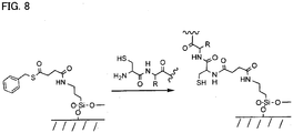
- the most preferable reaction scheme uses native chemical ligation between capture agents with N-terminal cysteines and thioester-derivatised surfaces as shown in Figure 8 .
- Native chemical ligation generates a peptide bond between an N-terminal cysteine on a peptide and a surface-attached thioester.
- a particular advantage of this embodiment of the current invention is that protection of peptide side chains is not required.
- a further particular advantage of this embodiment of the current invention is that the resulting surface-attached peptide has an internal cysteine that may be exploited for the formation of dimeric receptors by disulfide bond formation, or reaction between a thiol and a maleimide functionalised peptide.
- the capture agent is assembled on the substrate surface, a preferred reaction scheme is shown in Figure 10 .
- the first peptide is covalently bound to the functionalised substrate via reaction between a thioester group and an N-terminal cysteine residue via native chemical ligation.
- the multimeric capture agent is produced by formation of disulfide bonds between the peptides.
- a more preferable route for the preparation of thioester surfaces involves the reaction between an aminated surface and thiolane 2,4-diones of the type shown below:
- Thioester surfaces may also be made by derivatising hydroxylated surfaces with thioester silylchloride conjugates of the type shown below.
- the dimer When the capture agent is immobilised to a substrate through a covalent bond, the dimer may be constructed wherein the first and second peptides each have a thiol group (which may or may not be activated) located at a site in the peptide sequence that is on the N-terminal side of the ligand-binding site or on the C-terminal side of the ligand-binding site or located internally within a bipartite ligand-binding site.
- the thiol group moieties may have the same or opposite orientation as the ligand-binding residues and that the location of each thiol group in the first and second peptides is independent.
- the capture agent is immobilised on the substrate by a hydrophobic interaction between the capture agent and the substrate.
- the capture agents fabricated according to the method of the current invention comprise at least two peptide monomer units, the first and second monomer units each comprising at least one hydrophobic moiety, at least one reactive group and at least one ligand-binding moiety.
- the capture agent fabricated according to the method comprises two peptides, the first and second peptides each comprising at least one hydrophobic amino acid residue, at least one reactive group, and at least one ligand-binding moiety, wherein, the at least one hydrophobic amino acid residue and the at least one ligand-binding moiety are positioned in the peptide primary structure so as to result in a hydrophobic face, and a substantially non hydrophobic ligand-binding face.
- the hydrophobic face of the peptides forms the attachment moiety.
- each peptide comprises a plurality of hydrophobic amino acids forming the attachment moiety.
- the .first peptide for use in the method of the current invention comprises 4 to 40 hydrophobic amino acid residues, more preferably 6 to 25 and most preferably 6 to 12.
- the ligand-binding moiety comprises at least one amino acid. More preferably, the ligand-binding moiety comprises a plurality of amino acids.
- amino acids positioned on the ligand-binding face may also include hydrophobic residues, for example, aminobutyrate residues.
- each peptide for use in this embodiment comprises a primary structure comprising alternating hydrophobic and non hydrophobic amino acid residues, as shown in Figure 11 .
- peptide sequences which result in distribution of the side chains so as to result in a hydrophobic and substantially non hydrophobic face can be easily designed, for example, there may be three non hydrophobic amino acid residues between hydrophobic residues, or any combination of odd numbers of amino acids.
- the' peptide may comprise a combination of, for example, L-, D-, and beta- amino acids so as to result in a hydrophobic and a substantially non hydrophobic face.
- each amino acid positioned so as to be located on the ligand-binding face is selected from a set consisting essentially of fewer than 20 amino acids, more preferably fewer than 12 amino acids, even more preferably fewer than 6 amino acids and most preferably 4 amino acids.
- each peptide for use in this embodiment comprises 10% to 90% hydrophobic amino acid residues, more preferably, 20% to 80%, even more preferably, 30% to 70%, and most preferably 40% to 60% hydrophobic amino acid residues.
- the first peptide comprises 50% hydrophobic amino acid residues.
- the hydrophobic amino acids are selected from the group consisting of leucine, isoleucine, norleucine, valine, norvaline, methionine, tyrosine, tryptophan and phenylalanine. More preferably, the hydrophobic amino acids are phenylalanine.
- the capture agent is located on a hydrophobic substrate such that the substantially non hydrophobic ligand-binding face is accessible for ligand-binding.
- the substrate for use in the method may be any suitable hydrophobic substrate, for example, gold modified by hydrophobic organic thiol treatment, glass modified by surface treatment, or plastic.
- the substrate is plastic.
- the substrate may be coated in a hydrophobic compound which allows the capture agents to be immobilised thereon in the presence of a substantially aqueous solvent.
- the second peptide for use in this embodiment of the current invention comprises fewer amino acids than the first peptide, and contains fewer hydrophobic residues such that the interaction between the peptide and the hydrophobic surface is relatively weak.
- first and second peptides and the numbers of hydrophobic amino acid residues required to retain them on the substrate will depend upon the hydrophobicity of the surface and on the hydrophobic amino acids present in the first and second peptides, and also on the nature of the ligand to be bound.
- the amount of peptide retained at the substrate will depend upon the stringency of washing to which the substrate is subjected.
- the substrate is washed with, for example, 1.0 M NaCl in 10 mM tris-HCl (pH 8.0).
- the second peptide comprises 1-6 hydrophobic amino acid residues, more preferably, 2-5, and most preferably 2-4 hydrophobic amino acid residues on the hydrophobic face.
- the ligand-binding residues are positioned on the substantially non hydrophobic ligand-binding face.
- the reactive groups may be located in the primary peptide structure of the first and second peptides at any suitable position, for example, the reactive groups may be positioned in the primary peptide sequence such that they are positioned on the substantially non hydrophobic ligand-binding face of the peptides and located on the N-terminal side of the ligand-binding site.
- the reactive groups may be located in the primary peptide structure of the first and second peptides such that they are positioned on the substantially non hydrophobic ligand-binding face of the peptides, and in the first peptide, on the N-terminal side of the ligand-binding site, and in the second peptide to the C-terminal side of the ligand-binding site.
- the reactive group may be located in the primary peptide structure of the first and second peptides such that in the first peptide, it is positioned on the substantially non hydrophobic ligand-binding face of the peptides and to the N-terminal side of the ligand-binding site, and in the second peptide it is located on the opposite (hydrophobic) face to the ligand-binding site and to the C-terminal side of the ligand-binding site.
- the reactive group on the first peptide is located in the primary amino acid structure on the substantially non hydrophobic ligand-binding face and to the N-terminal side of the ligand-binding site and in the second peptide, in the hydrophobic face and to the N-terminal side of the ligand-binding site as shown in Figure 10 .
- the capture agents are bound to the substrate so as to produce an array.
- the array may take any' convenient form.
- the method of the invention is applicable to all types of "high density" arrays, including single-molecule arrays.
- the array comprises a number of discrete addressable spatially encoded loci.
- each locus on the array comprises a different capture agent, and more preferably each locus comprises multiple copies of the capture agent.
- immobilisation of molecules e.g. peptides
- the terms "immobilised” and “attached” are used interchangeably herein and both terms are intended to encompass hydrophobic interactions, unless indicated otherwise, either explicitly or by context. Generally all that is required is that the molecules (e.g. peptides) remain immobilised or attached to the substrate under the conditions in which it is intended to use the substrate, for example in applications requiring peptide ligand-binding.
- Certain embodiments of the invention may make use of solid supports comprised of an inert substrate or matrix (e.g. glass slides, polymer beads etc) which has been "functionalised", for example by application of a layer or coating of an intermediate material comprising reactive groups which permit hydrophobic attachment of biomolecules such as peptides.
- an inert substrate or matrix e.g. glass slides, polymer beads etc
- an intermediate material comprising reactive groups which permit hydrophobic attachment of biomolecules such as peptides.
- distinct regions on the array comprise multiple peptide molecules.
- each site on the array comprises multiple copies of one individual peptide.
- the first peptide has the structure set out in SEQ ID No 1; (Phe-Gly) n -Phe-Cys-Phe-X-Phe-Y-Phe-Z-Phe-Gly-Phe where X, Y, and Z are the ligand-binding residues and Cys provides a nucleophilic thiol used for dimer formation.
- the second peptide has the preferred structure set out in SEQ ID No 2; CysS(N)P-X'-Phe-Y'-Phe-Z'-Phe where X', Y', and Z' are the ligand-binding residues and CysS(N)P is an activated thiol used for dimer formation (most preferably activated with either a thionitropyridyl group or a thiopyridyl group).
- the capture agents fabricated according to the method of the current invention are dispensed onto a suitable substrate to form an addressable spatially encoded array of combinatorially varying dimers.
- the peptides are individually dispensed on to the substrate using a non-contact dispenser (Piezorray System, Perkin Elmer LAS) and assembled in situ.
- the capture agent is immobilised through a covalent or hydrophobic interaction.
- kits comprising a multimeric capture agent fabricated according to the method described herein and a suitable substrate for immobilisation.
- the kit may comprise first and second monomer units produced for use in the method described herein .
- the kit further comprises a suitable substrate.
- Also described herein is a method of identifying a multimeric capture agent fabricated according to the method which binds to a ligand of interest, said method comprising producing an array of combinatorial capture agents according to any previous aspect, contacting the ligand of interest with the array, and identifying to which capture agent(s) the ligand binds.
- bind is intended to encompass direct or indirect, covalent or non-covalent attachment, unless indicated otherwise, either explicitly or by context.
- covalent attachment may be preferred, but generally all that is required is that the ligands remain bound to the immobilised peptide under the conditions in which it is intended to use the substrate, for example in applications requiring further ligand receptor interactions.
- the binding of the ligand to a capture agent can be identified in various ways known in the art, for example, the ligand or the capture agent may be' labelled so that the location on the array to which the ligand binds can be identified.
- This label may, for example, be a radioactive or fluorescent label using, for example, fluorophores.
- binding of the ligand of interest to a capture agent may be detected by a variety of other techniques known in the art, for example, calorimetry, absorption spectroscopy, NMR methods, atomic force microscopy and scanning tunnelling microscopy, electrophoresis or chromatography, mass spectroscopy, capillary electrophoresis, surface plasmon resonance detection, surface acoustic wave sensing and numerous microcantilever-based approaches.
- the dimeric capture agents arrays produced by the methods of the current invention can be used to identify any analyte of choice, since the specific ligand which will be bound by the capture agent will be dependent upon the length and sequence of the peptides from which the capture agent is formed.
- the ligand comprises a eukaryotic cell, a prokaryotic cell, a virus, a bacteriophage, a prion, a spore, a pollen grain, an allergen, a nucleic acid, a protein, a peptide, a carbohydrate, a lipid, an organic compound, or an inorganic compound.
- the ligands are preferably physiological or pharmacological metabolites and most preferably physiological or pharmacological metabolites in human or animal bodily fluids that may be used as diagnostic or prognostic healthcare markers.
- spacer amino acid refers to an amino acid, a synthetic amino acid, an amino acid analogue or amino acid mimetic in which the side chains play no part in ligand-binding.
- capture agent refers to a dimeric molecule having a structure such that when a ligand is brought into contact with the capture agent it is bound thereto.
- peptide refers to a chain comprising two or more amino acid residues, synthetic amino acids, amino acid analogues or amino acid mimetics, or any combination thereof.
- peptide, oligopeptide and polypeptide are used interchangeably in this specification.
- oligonucleotide and polynucleotide refer to a chain of two or more nucleotides, and are used interchangeably in this specification.
- substantially enantiomerically pure indicates that the residue comprises substantially one type of isomer, with any other isomeric forms being there only as an impurity.
- the term located in space in a manner favourable to ligand-binding indicates that the side chains of the peptides which make up the multimeric capture agent are positioned such that they are able to contact and interact with a ligand.
- substantially non hydrophobic means comprising substantially more hydrophilic residues than hydrophobic residues.
- Figure 1 shows a schematic representation of a method of producing capture' agents
- a first set of monomer units (A) is prepared on a solid phase.
- the monomer units comprise a ligand-binding moiety (R1 - R4) and a reactive group X. If wished X may be protected during synthesis and then deprotected before use.
- a second set of monomer units (B) is prepared on a solid phase.
- These monomer units comprise a ligand-binding moiety (R'1 - R'4), a reactive group Y, which may be protected during synthesis and then deprotected before use, and an attachment moiety Z. If wished Z may also be protected during synthesis and then deprotected before use.
- Each of the monomer units in set (A) is cleaved off the solid support to give monomer units (C) in solution.
- Each of the monomer units in set (B) is cleaved off the solid support to give monomer units (D) in solution.
- Each of the monomer units in set D is then contacted with the surface of a solid support (E) at a spatially encoded location in an array such that Z is used to bring about attachment to the said surface.
- Reactions are then performed wherein surface-bound monomer units (F) from set D are reacted with an excess or equimolar amount of a given solution phase monomer unit (C) such that residue X reacts with residue Y to form a dimeric structure (G) bound to the solid phase.
- the arrayed and spatially encoded dimeric structures (G) can then be used for binding to ligands of interest that will bind with suitable affinity, and selectivity.
- Figure 2 shows a schematic representation of a further method of producing capture agents.
- a first set of monomer units (A) is prepared on a solid phase.
- the monomer units comprise a ligand-binding moiety (R1 - R4) and a reactive group X, which may be protected during synthesis and then deprotected before use.
- a second set of monomer units (B) is also prepared on a solid phase.
- These monomer units comprise a ligand-binding. moiety (R'1 - R'4) and a reactive group Y, which may be protected during synthesis and then deprotected before use, and an attachment moiety Z. If wished Z may also be protected during synthesis and then deprotected before use.
- Each of the monomer units (B) is cleaved off the solid support to give monomer units (C) in solution. Reactions are then performed wherein a given solid phase-bound monomer unit from set (A) is reacted with an excess of a given solution phase monomer unit (C) such that residue X reacts with residue Y to form a dimeric structure (D) bound to the solid phase.
- Each dimeric structure (D) bound to the solid phase is then cleaved off the solid support to give a solution phase dimeric structure (E).
- Each solution phase dimeric structure (E) is finally contacted with a solid surface (F) at a spatially encoded location in an array such that group Z is used to attach the dimeric structure to the said surface.
- the arrayed and spatially encoded dimeric structures (G) can then be used for binding to ligands of interest that will bind with suitable affinity, and selectivity.
- Figure 3 shows a schematic representation of a further method of producing capture agents.
- a first set of monomer units (A) is prepared on a solid phase.
- the monomer units comprise a ligand-binding moiety (R1 - R4) and a reactive group X. If wished X may be protected during synthesis,and then deprotected before use.
- a second set of monomer units (B) is prepared on a solid phase.
- These monomer units comprise a ligand-binding moiety (R'1 - R'4), a reactive group Y, which may be protected during synthesis and then deprotected before use, and an attachment moiety Z. If wished Z may also be protected during synthesis and then deprotected before use.
- Each of the monomer units in set (A) is cleaved off the solid support to give monomer' units (C) in solution.
- Each of the monomer units in set (B) is cleaved off the solid support to give monomer units (D) in solution.
- Each of the monomer units in set D is then contacted with an excess or equimolar amount of a given solution phase monomer unit (C) and the surface of a solid support (E) at a spatially encoded location in an array such that Z is used to bring about attachment to the said surface and such that residue X reacts with residue Y to form a dimeric structure (G) bound to the solid phase.
- the arrayed and spatially encoded dimeric structures (G) can then be used for binding to ligands of interest that will bind with suitable affinity, and selectivity.
- the most significant advantage of the current invention is the 'squaring' (or raising to a higher power) of sequence diversity by the combinatorial joining of pairs (or greater numbers) of monomer units at the array surface.
- residue side chains projecting in front of the plane of the paper represent the combinatorially varied 'ligand-binding face'.
- the residue side chains projecting behind the plane of the paper represent the 'hydrophobic face' (or negative control residues).
- microtitre plate was imaged at 200 ⁇ m resolution on a Typhoon Trio Plus variable mode imager (Amersham Biosciences) with the green (532 nm) laser and the 580 BP 30 filter at the PMT voltages indicated below and at normal sensitivity.
- the scan height was set at +3 mm and the sample was pressed during scanning.
- the peptides were allowed to evaporate to dryness overnight in the dark and the microtitre plate was again scanned as described above.
- the polypropylene sheet was wiped with 50% (v/v) aqueous acetonitrile prior to use.
- the slide was imaged at 10 ⁇ m resolution on a Typhoons Trio Plus variable mode imager (Amersham Biosciences) with the green (532 nm) laser and the 580 BP 30 filter at a PMT voltage of 600 V and at normal sensitivity.
- the scan height was set at the platen and the samples were pressed during scanning.
- the fluorescence image was analysed using ImageQuant TL v2003.03 (Amersham Biosciences).
- the lower half of the slide (containing the test array) was then washed in 100 ml of 1 M NaCl containing 10 mM 'tris-HCl (pH 8.0) for one minute and were re-scanned as described above.
- the peptide samples were allowed to evaporate to dryness in the dark.
- the peptide samples were allowed to evaporate to dryness in the dark.
- the dried peptide samples in wells 1-10 were incubated with 250 ⁇ l of 1 M NaCl in 10 mM tris-HCl (pH 8.0) for the time indicated below at room temperature. All supernatants were pipetted up and down 8 times after incubation and the supernatants were then removed and placed in the wells of the bottom row of the microtitre plate.
- the residual surface-bound peptides in all twelve wells were finally resuspended in 50 ⁇ l of 10 mM, tris-HCl (pH 8.0) in 50% (v/v) aqueous acetonitrile and the microtitre plates were imaged at 200 ⁇ m resolution on a Typhoon Trio Plus variable mode imager (Amersham Biosciences) with the green (532 nm) laser and the 580 BP 30 filter at the PMT voltages indicated below and at normal sensitivity. The scan height was set at +3 mm and the sample was pressed during scanning.
- the peptide samples were allowed to evaporate to dryness in the dark.
- peptide samples in the top two rows of the microtitre plates were then incubated for 15 minutes at room temperature in 250 ⁇ l of 1 M NaCl in 10 mM tris-HCl (pH 8.0). After incubation, the wash buffer was pipetted up and down eight times in the well before removing the supernatant.
- microtitre plates were imaged at 200 ⁇ m resolution on a Typhoon Trio Plus variable mode imager (Amersham Biosciences) with the green (532 nm) laser and the 580 BP 30 filter at the PMT voltages indicated below and at normal sensitivity.
- the scan height was set at the platen and the sample was pressed during, canning.
- the peptide samples were allowed to evaporate to dryness in the dark.
- peptide samples in the top two rows of the microtitre plates were then incubated for 15 minutes at room temperature in 250 ⁇ l of 1 M NaCl in 10 mM tris-HCl (pH 8.0). After incubation, the wash buffer was pipetted up and down eight times in the well before removing the supernatant.
- microtitre plates were imaged at 200 ⁇ m resolution on a Typhoon Trio Plus variable mode imager (Amersham Biosciences) with the green (532 nm) laser and the 580 BP 30 filter at the PMT voltages indicated below and at normal sensitivity.
- the scan height was set at +3 mm and the sample was pressed during scanning.
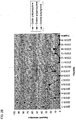
- peptides were synthesised that contain a 'surface-binding face' consisting of seven phenylalanyl residues. These peptides also contain a central region consisting of charged and uncharged residues and a variable penultimate residue.
- the variable penultimate residue was alanyl, seryl, cysteiyl, or nitropyridylthio activated cysteiyl.
- TAMRA-labelled fluorescent peptides were also synthesised that contain an N-terminal TAMRA fluorophore attached to a glycyl residue that is attached to a variable C-terminal residue.
- the variable C-terminal residue was alanyl, seryl, cysteiyl, or nitropyridylthio activated cysteiyl.
- the peptides SB-1 to SB-4 and TLSP-1 to TLSP-4 were used in order to investigate dimer formation.
- the SB peptides were mixed with the TLSP peptides and both were then dried down together onto a polypropylene surface prior to washing the wells and assaying for retained fluorescent material.
- the microtitre plate was imaged at 200 ⁇ m resolution on a Typhoon Trio Plus variable mode imager (Amersham Biosciences) with the green (532 nm) laser and the 580 BP 30 filter at a PMT voltage of 500 V and at normal sensitivity.
- the scan height was set at +3 mm and the sample was pressed during scanning.
- the fluorescence image was analysed using ImageQuant TL v2003.03 (Amersham Biosciences).
- the yield of dimer is assayed by the retention of fluorescently labelled peptide which is conditional upon the presence of an unlabelled peptide that can bind to both the polypropylene surface and to the fluorescently labelled peptide.
- Dimer formation is also observed when the surface peptide possesses an S-nitropyridyl activated thiol group and the solution peptide also possesses an S-nitropyridyl activated thiol group; when the surface peptide possesses a free thiol group and the solution peptide also possesses a free thiol group; and when the surface peptide possesses an S-nitropyridyl activated thiol group and the solution peptide possesses a free thiol group.
- Free thiol coupling to free thiols may be due to simple aerobic oxidation, forming disulfide bonds.
- S-nitropyridyl activated thiol coupling to S-nitropyridyl activated thiols may be a result of incomplete thiol activation, leaving some free thiols able to 'react with the remaining S-nitropyridyl activated thiols, or some other mechanism.
- peptide dimers are fabricated on a planar plastic surface using a Piezorray (PerkinElmer LAS) non-contact dispenser.
- the Piezorray (PerkinElmer LAS) is specifically designed for pipetting nanolitre volumes to dense arrays. Liquid volumes are controlled by a piezoelectric tip.
- the Piezorray system contains a source plate holder, an ultrasonic washbowl, a computer and monitor, and a bottle for system liquid.
- Polypropylene sheet was obtained from SBA plastics (http://www.sba.co.uk/, Propylex Natural Polypropylene Sheet 2440 x 1220 x 1 mm) and was wiped with 50% (v/v) aqueous acetonitrile prior to use.
- the microtitre plate was imaged at 10 ⁇ m resolution on a Typhoon Trio Plus variable mode imager (Amersham Biosciences) with the green (532 nm) laser and the 580 BP 30 filter at a PMT voltage of 400 V and at normal sensitivity.
- the scan height was set at the platen and the sample was pressed during scanning.
- the fluorescence image was analysed using ImageQuant TL v2003.03 (Amersham Biosciences).
- the yield of dimer is assayed by the retention of fluorescently labelled peptide that is conditional upon the pretence of an unlabelled peptide that can bind to both the polypropylene surface and to the' fluorescently labelled peptide.
- Dimer formation is therefore seen when the surface peptide possesses a free thiol group and the solution peptide possesses an S-nitropyridyl activated thiol group.
- the simple protocol (without glycerol to prevent evaporation) gives a higher yield of dimer.
- the slide was imaged at 10 ⁇ m resolution on a Typhoon Trio Plus variable mode imager (Amersham Biosciences) with the green (532 nm) laser and the 580 BP 30 filter at a PMT voltage of 500V and at normal sensitivity.
- the scan height was set at the platen.
- the fluorescence image was analysed using ImageQuant TL v2003.03 (Amersham Biosciences).
- Fluorescent signal is observable for each L1-P1. peptide column dispensed to the array. This indicates that each of the L1-P1 peptides has been successfully dispensed, and is capable of dimer formation. The fluorescent signal is also observable for each L1-P2 peptide row dispensed to the array. This indicates that each of the L1-P2 peptides has been successfully dispensed, and is capable of dimer formation.
- the dimer fluorescence is greater for the samples with only TAMRA-labelled P2 peptides compared to the dimer fluorescence for the 16x16 array fabricated with both unlabelled P2 peptides and TAMRA-labelled P2 peptides competing for the L1-P1 peptide thiol groups. This indicates that all of the L1-P2 peptides have successfully competed with their TAMRA-labelled counterparts and have therefore successfully formed peptide dimers between all sixteen L1-P1 peptides and all sixteen L1-P2 peptides.
Landscapes
- Life Sciences & Earth Sciences (AREA)
- Health & Medical Sciences (AREA)
- Chemical & Material Sciences (AREA)
- Engineering & Computer Science (AREA)
- Molecular Biology (AREA)
- Immunology (AREA)
- Biochemistry (AREA)
- Biomedical Technology (AREA)
- Urology & Nephrology (AREA)
- Hematology (AREA)
- Organic Chemistry (AREA)
- General Health & Medical Sciences (AREA)
- Proteomics, Peptides & Aminoacids (AREA)
- Medicinal Chemistry (AREA)
- Physics & Mathematics (AREA)
- Analytical Chemistry (AREA)
- Biophysics (AREA)
- Microbiology (AREA)
- Biotechnology (AREA)
- General Physics & Mathematics (AREA)
- Food Science & Technology (AREA)
- Cell Biology (AREA)
- Pathology (AREA)
- Genetics & Genomics (AREA)
- Bioinformatics & Cheminformatics (AREA)
- Wood Science & Technology (AREA)
- Zoology (AREA)
- Bioinformatics & Computational Biology (AREA)
- General Engineering & Computer Science (AREA)
- Peptides Or Proteins (AREA)
Abstract
Description
- The currant invention relates to novel methods of fabricating a dimeric capture agent at a surface. Also described are capture agents produced by the novel method, and arrays of such capture agents.
- The combinatorial production of molecules such as peptides is well known. This technique has provided a powerful tool, enabling the production of large libraries of molecules which can be used in techniques such as high throughout screening. Examples of' such techniques and their uses in identifying molecules of interest are disclosed in, for example, J. Org. Chem.,63, 8696, (1998), where a 1,000-peptide library of 3-mers was reacted with a dansyl 'tweezer' molecule in water. 3% of the library bound to the 'tweezer'. In J. Comb. Chem., 5, 794, (2003), a tripodal cyclotriveratrylene scaffold was described for split and mix synthesis and a library with ∼2,000 members was described.
- Nature Biotechnology, 22, 568, (2004), Dario Neri et al, describes two libraries of organic molecule binders with attached DNA tags. DNA complementarity was used to make a higher diversity library. A further library was also made using triplex formation. 24 mer oligos were used for complex assembly. Organic molecule deconvolution was achieved by sequencing the attached DNA tags or by binding to oligonucleotide arrays. Binders were generated to protein with nM affinities.
- Bioconjugate Chem., 12, 346, (2001), describes fabrication of peptide microarrays and small molecule microarrays. This document also discloses that chemoselective ligation can be used with peptides and slide surfaces. In this technique, an N-terminal cysteiyl residue reacts with an alpha keto aldehyde on the slide surface to give a thiazolidine ring. Others have used the free radical Michael addition between a free thiol and a maleimide.
- Further, Chem. Commun., 581, (2005), describes a strategy to build complex libraries of cyclic peptides on a surface through photolithographic synthesis. A differential protection strategy is used for the combinatorial addition of side chains to a prefabricated core.
US 5,491,074 discloses the association of peptide librairies. - In order to achieve the necessary diversity required for a meaningful library, the known methods require a large number of syntheses to be undertaken, thus increasing the time required, and cost of producing the library.
- It is an object of the current invention to provide a faster and cheaper method of producing a library of molecule having the required diversity.
- The present invention provides a method of fabricating a set of dimeric peptide capture agents each of said capture agents being suitable for binding a ligand and comprising first and second peptide monomer units each comprising a ligand binding moiety and said first and second peptide monomer units being covalently linked to form a dimer, said method comprising the steps of:
- a) synthesising in a combinatorial manner from first and second sets of amino acids, wherein each amino acid set is different, first and second peptide monomer units, each peptide monomer unit having a different primary amino acid sequence, each said first peptide monomer units comprising a first reactive group and an attachment moiety comprising hydrophobic or covalent means for immobilisiing the dimeric capture agent on a substrate and each said second peptide monomer unit comprising a second reactive group; and
- b) reacting said first peptide monomer units with said second peptide monomer units such that the first and second reactive groups react to form a covalent bond whereby a combinatorially-varied set of dimeric peptide capture agents is formed, wherein the combinatorial synthesis is carried out on a solid phase and prior to step (b) said first and second peptide monomer units are cleaved from the solid phase.
- Preferably, the reactive groups are thiol groups. More preferably, the method comprises covalently linking the capture agents to the substrate. More preferably, the method comprises attaching capture agents to the substrate by native chemical ligation between thioester-derivatised capture agents and cysteine-derivatised surfaces. More preferably the method comprises attaching the capture agents to the substrate by native chemical ligation between capture agents with N-terminal cysteines and thioester-derivatised surfaces. Alternatively, the method comprises immobilising the capture agent on the substrate by hydrophobic interaction.
- Preferably the method includes the further step (c) of immobilising the set of dimeric peptide capture agents on a substrate by means of the attachment moiety,
wherein step (b) is performed before, simultaneously with or subsequent to step (c).
Preferably, the first and second peptide monomer units each comprise between 2 and 50 amino acids. More preferably, said first and second peptides comprise 3 to 10 ligand binding amino acid residues. - Preferably, the said first and second peptides include amino acids for ligand binding selected from amino acids with side chains providing a positive charge for ligand binding, amino acids providing a hydroxyl group capable of acting as a hydrogen bond donor and/or acceptor for ligand binding, amino acids providing a hydrophobic moiety for ligand binding and amino acids providing a negative charge for ligand binding.
- Preferably the attachment moiety is formed by each peptide comprising a plurality of hydrophobic amino acids. More preferably, the first peptide comprises a primary structure comprising alternating hydrophobic and non-hydrophobic amino acid residues.
- Preferably the method comprises selecting the hydrophobic amino acids from the group consisting of leucine, isoleucine, norleucine, valine, norvaline, methionine, tyrosine, tryptophan and phenylalanine.
- Preferably, the first peptide has the sequence set out in SEQ ID No. 1.
- Preferably the second peptide has the sequence set out in SEQ ID No. 2.
- Schematic representations of possible methods of fabricating dimeric capture agents are shown in
figures 1 ,2 and3 and described in Example 1. - There is also described herein a method of fabricating a dimeric capture agent for binding a ligand, or to form part of the set fabricated above said capture agent comprising at least first and second peptide monomers units,
said first monomer unit further comprising a first ligand-binding moiety, a first reactive group and an attachment moiety,
said second monomer unit further comprising a second ligand-binding moiety, and a second reactive group,
wherein the reactive groups may be the same or different for each monomer unit,
said method comprising the steps of; - Preferably, the described method further includes the step of immobilising the capture agent on a substrate.
- The present invention will now be further described. In the following passages, different embodiments' of the invention are defined in more detail. Each embodiment so defined may be combined with any other embodiment or embodiments unless clearly indicated to the contrary. In particular, any feature indicated as being preferred or advantageous may be combined with any other feature or features indicated as being preferred or advantageous.
- The first and second peptide monomer units are covalently linked. It will be understood that immobilisation may be, for example, by covalent, or hydrophobic, interactions.
- The attachment moiety comprises covalent or hydrophobic means for immobilising the capture agent on the substrate.
- By polypeptide, it is meant a chain of 2 or more amino acids.
- The first and second monomer units are synthesised. The first and second monomer units are synthesised on a solid phase and are different. The monomer units are cleaved from the solid phase prior to reacting said omits to form a co-valent bond.
- Synthesis of polynucleotides and polypeptides is well known to those skilled in the art.
- Syntheses of peptides and their salts and derivatives, including both solid phase and solution phase peptide syntheses, are well established. See, e.g., Stewart, et al. (1984) Solid Phase Peptide Synthesis (2nd Ed.); and Chan (2000) "FMOC Solid Phase Peptide Synthesis, A Practical Approach," Oxford University Press. Peptides may be synthesized using an automated peptide synthesizer (e.g., a Pioneer™ Peptide Synthesizer, Applied Biosystems, Foster City, CA). For example, a peptide may be prepared on Rink amide resin using FMOC solid phase peptide synthesis followed by trifluoroacetic acid (95%) deprotection and cleavage from the resin.
- When the capture agent comprises a peptide dimes, the first and second peptides have different primary amino acid sequences.
- It will be further apparent that the first and second peptides can be synthesised from first and second amino acid sets and that each amino acid set is different.
- Preferably, the first and second peptides are between 2 and 100 amino acids in length, more preferably, 2 to 50 amino acids in length, and most preferably, 5 to 25 amino acids in length.
- Preferably, each amino acid forming the ligand-binding moiety is selected from a set consisting essentially of fewer than 20 amino acids, more preferably fewer than 12 amino acids, even more preferably fewer than 6 amino acids and most preferably 4 amino acids.
- It will be understood that each amino acid in the set can be an L-amino acid, a D-amino acid, an amino acid mimetic, a spacer amino acid, a beta amino acid, or any other chiral amino acid monomer. Preferably, the amino acids are L-amino acids and/or D-amino acids.
- Preferably, each amino acid in the set is substantially enantiomerically pure.
- Preferably, the first and second peptides for use in the method of the current invention each contains 10 or fewer ligand-binding residues; more preferably, 8 or fewer; more preferably, 6 or fewer; even more preferably, 4 or fewer; and most preferably 3 or fewer.
- In a preferred embodiment, the reactive groups may be protected during peptide synthesis and deprotected prior to use in production of capture agents according to the first aspect. Such techniques are well known to those skilled in the art, for example, standard FMOC-based solid-phase peptide assembly. In this technique, resin bound peptides with protected side chains and free amino termini are generated. The amino groups at the N-terminus may then be reacted with any compatible carboxylic acid reactive group conjugate under standard peptide synthesis conditions. For example, cysteine with a trityl or methoxytrityl protected thiol group could be incorporated. Deprotection with trifluoroacetic acid would yield the unprotected peptide in solution.
- Preferably, said reactive groups for use in any embodiment of the current invention are selected from, but not limited to, thiol groups, maleimide, cyclopentadiene, azide, phosphinothioesters, thioesters and (nitro) thiopyridine activated thiols. More preferably, the reactive groups are thiol groups. Preferably, when' the reactive groups are thiol groups, at least one thiol group is an activated thiol. Preferably, the thiol group is activated with either a thionitropyridyl or thiopyridyl group.
- The reaction scheme outlined in
Figure 4 shows a possible route for generating peptides comprising various reactive groups. - It will be understood that any suitable reaction may be used in the method of the current invention to form the multimeric capture agent, for example, Diels Alder reaction between e.g. cyclopentadienyl functionalised peptides and maleimide functionalised peptides, Michael reaction between a thiol functionalised peptide and a maleimide functionalised peptide, reaction between a thiol functionalised peptide and a peptide containing an activated thiol group (activated with, for example, a (nitro) thiopyridine moiety) to form a disulfide; Staudinger ligation between an azide functionalised peptide and a phosphinothioester functionalised peptide, and native chemical ligation between a thioester and a N-terminal cysteine.
- It will be apparent that, depending upon the amino acid residues present in the peptides, the capture agents will have different characteristics. For example, the side chains may provide a positive charge for ligand binding. Preferably, the positive charge is provided by a lysyl residue (four CH2 groups between the peptide chain and the positive charge), an ornithyl residue (three CH2 groups between the peptide chain and the positive charge) or most preferably, a diaminobutyryl residue (with two CH2 groups between the peptide chain and the positive charge).
- The amino acid may alternatively provide a hydroxyl group capable of acting as a hydrogen bond donor and/or acceptor for ligand binding. Preferably, the hydroxyl group is provided by a seryl residue (one CH2 group between the peptide chain and the OH group), or more preferably a homoseryl residue (with two CH2 groups between the peptide chain and the OH group).
- The amino acid may provide a hydrophobic moiety for ligand binding. Preferably, an alanyl residue (no CH2 group between the peptide chain and the methyl group) or more preferably, an aminobutyryl residue (with one CH2 group between the peptide chain and the methyl group) provides the hydrophobic moiety.
- Alternatively, the amino acid may provide' a negative charge for ligand binding. Preferably, the negative charge is provided by a glutamyl residue (two CH2 groups between the peptide chain and the carboxylate group), or more preferably, an aspartyl residue (one CH2 group between the peptide chain and the carboxylate group).
- The peptides are produced from the set of amino acids in a combinatorial manner, as is well known in the art, such that all possible combinations of amino acids present in the set may be produced, for example, if there are N amino acids in the set and the peptide is of length L, the complete set will comprise NL peptides.
- In a preferred embodiment, a subset of the possible combinatorial peptides which can be produced from any given set of amino acids will be employed. The subset can be determined through the inclusion of specific rules in the synthesis of the peptide, for example, maximum and minimum levels of each amino acid in the set can be provided, or maximum and minimum levels of the percentage hydrophobic amino acids incorporated can be provided.
- The method of the current invention results in the production of capture agents having increased diversity. This arises from the fact that the combinatorially fabricated capture agents produced by the method are multimeric. For example, because the multimeric capture agent is a dimer, the possible diversity for any given length of ligand-binding moiety is squared due to the presence of two peptide chains. Therefore, it is necessary to carry out a reduced number of initial syntheses.
- In a preferred embodiment, the peptides are immobilised such that the' side chains are located in space in a manner which is favourable for ligand-binding.
- When the capture agents are immobilised through a covalent interaction, this may be achieved by, for example, synthesising peptides having alternating L- and D- amino acids as shown in
Figure 5 . - Alternatively, the peptides may be synthesised using a set comprising beta amino acids as shown in
Figure 6 , or any other chiral amino acid monomer with an even number of atoms per peptide repeat unit. - In one preferred embodiment, the peptides are synthesised such that only every second amino acid in the ligand binding region is varied, as shown in
Figure 7 . - This embodiment has the advantage that the side' chains are spaced in the most natural and advantageous manner for ligand-binding.
- It will be obvious to the skilled person that each peptide can comprise one or more of the above types of amino acid and that the specific combinations employed will affect the characteristics of the capture agent containing the varying peptide chains.
- When immobilisation of the capture agents to the substrate is via covalent attachment, the capture agents maybe "arrayed" on a substrate, and the array may take any convenient form. Thus, the method of the invention is applicable to all types of "high density" arrays, including single-molecule arrays.
- Preferably, the covalently immobilised capture agents produced by the method of the first aspect are located at discrete spatially encoded loci on an array. Preferably, all of the said capture agents at a given locus on the array are comprised of the same pairs of peptides. More preferably, each locus on the array comprises a different capture agent.
- When referring to immobilisation of molecules (e.g. peptides) to a substrate, the terms "immobilised" and "attached" are used interchangeably herein and in this embodiment, both terms are intended to encompass direct or indirect, covalent attachment, unless indicated otherwise, either explicitly or by context.
- Certain embodiments of the invention may make use of substrates comprised of an inert substrate or matrix (e.g. glass slides, polymer beads etc) which has been "functionalised", for example by application of a layer or coating of an intermediate material comprising reactive groups which permit covalent attachment to biomolecules such as peptides. Examples of such supports include, but are not limited to, polyacrylamide hydrogels supported on an inert substrate such as glass. In such embodiments, the biomolecules (e.g. peptides) may be directly covalently attached to the intermediate material (e.g. the hydrogel) but the intermediate material may itself be non-covalently attached to the substrate or matrix (e.g. the glass substrate). The term "covalent attachment to a substrate" is to be interpreted accordingly as encompassing this type of arrangement.
- In multi-peptide arrays, distinct regions on the array comprise multiple peptide molecules. Preferably, each site on the array comprises multiple copies of one individual peptide dimer.
- Preferred reaction schemes for the covalent attachment of capture agents to substrates include, but are not limited to; reaction between sulfhydryls and maleimide derivatised surfaces, Diels-Alder reaction between maleimide derivatised surfaces and diene functionalised capture agents, azide and
acetylene 3+2 cycloaddition, thiazolidine ring formation, and the modified Staudinger ligation. Alternatively, covalent attachment of the capture agents to the substrates may be effected in the reverse fashion, for example by reaction between a thiol derivatised surface and maleimide substituted peptides. - In a particularly preferred embodiment, native chemical ligation between thioester-derivatised capture agents and cysteine-derivatised surfaces that present both the amino group and the sulfhydryl group of the cysteine is used to covalently link the capture agents to the substrate.
- The most preferable reaction scheme uses native chemical ligation between capture agents with N-terminal cysteines and thioester-derivatised surfaces as shown in
Figure 8 . - Native chemical ligation generates a peptide bond between an N-terminal cysteine on a peptide and a surface-attached thioester. A particular advantage of this embodiment of the current invention is that protection of peptide side chains is not required. A further particular advantage of this embodiment of the current invention is that the resulting surface-attached peptide has an internal cysteine that may be exploited for the formation of dimeric receptors by disulfide bond formation, or reaction between a thiol and a maleimide functionalised peptide.
- The preferred reaction scheme for the preparation of thioester functionalised glass surfaces is shown in
Figure 9 . - If the capture agent is assembled on the substrate surface, a preferred reaction scheme is shown in
Figure 10 . In this embodiment, the first peptide is covalently bound to the functionalised substrate via reaction between a thioester group and an N-terminal cysteine residue via native chemical ligation. The multimeric capture agent is produced by formation of disulfide bonds between the peptides. - A more preferable route for the preparation of thioester surfaces involves the reaction between an aminated surface and
thiolane 2,4-diones of the type shown below:
- Thioester surfaces may also be made by derivatising hydroxylated surfaces with thioester silylchloride conjugates of the type shown below.

- When the capture agent is immobilised to a substrate through a covalent bond, the dimer may be constructed wherein the first and second peptides each have a thiol group (which may or may not be activated) located at a site in the peptide sequence that is on the N-terminal side of the ligand-binding site or on the C-terminal side of the ligand-binding site or located internally within a bipartite ligand-binding site. In any of these embodiments, it will be clear that the thiol group moieties may have the same or opposite orientation as the ligand-binding residues and that the location of each thiol group in the first and second peptides is independent.
- In an alternative embodiment, the capture agent is immobilised on the substrate by a hydrophobic interaction between the capture agent and the substrate.
- In this embodiment, the capture agents fabricated according to the method of the current invention, comprise at least two peptide monomer units, the first and second monomer units each comprising at least one hydrophobic moiety, at least one reactive group and at least one ligand-binding moiety.
- The capture agent fabricated according to the method comprises two peptides, the first and second peptides each comprising at least one hydrophobic amino acid residue, at least one reactive group, and at least one ligand-binding moiety, wherein, the at least one hydrophobic amino acid residue and the at least one ligand-binding moiety are positioned in the peptide primary structure so as to result in a hydrophobic face, and a substantially non hydrophobic ligand-binding face.
- It will be understood that in this' embodiment of the method of the current invention, the hydrophobic face of the peptides forms the attachment moiety.
- Preferably, each peptide comprises a plurality of hydrophobic amino acids forming the attachment moiety.
- Preferably, the .first peptide for use in the method of the current invention comprises 4 to 40 hydrophobic amino acid residues, more preferably 6 to 25 and most preferably 6 to 12.
- Preferably, the ligand-binding moiety comprises at least one amino acid. More preferably, the ligand-binding moiety comprises a plurality of amino acids.
- It will be understood that amino acids positioned on the ligand-binding face may also include hydrophobic residues, for example, aminobutyrate residues.
- Preferably, each peptide for use in this embodiment comprises a primary structure comprising alternating hydrophobic and non hydrophobic amino acid residues, as shown in
Figure 11 . - It will be understood by the skilled person that other peptide sequences which result in distribution of the side chains so as to result in a hydrophobic and substantially non hydrophobic face can be easily designed, for example, there may be three non hydrophobic amino acid residues between hydrophobic residues, or any combination of odd numbers of amino acids. Alternatively, the' peptide may comprise a combination of, for example, L-, D-, and beta- amino acids so as to result in a hydrophobic and a substantially non hydrophobic face.
- Preferably, each amino acid positioned so as to be located on the ligand-binding face is selected from a set consisting essentially of fewer than 20 amino acids, more preferably fewer than 12 amino acids, even more preferably fewer than 6 amino acids and most preferably 4 amino acids.
- Preferably, each peptide for use in this embodiment comprises 10% to 90% hydrophobic amino acid residues, more preferably, 20% to 80%, even more preferably, 30% to 70%, and most preferably 40% to 60% hydrophobic amino acid residues.
- In a particularly preferred embodiment, the first peptide comprises 50% hydrophobic amino acid residues.
- Preferably, the hydrophobic amino acids are selected from the group consisting of leucine, isoleucine, norleucine, valine, norvaline, methionine, tyrosine, tryptophan and phenylalanine. More preferably, the hydrophobic amino acids are phenylalanine.
- In a preferred embodiment, the capture agent is located on a hydrophobic substrate such that the substantially non hydrophobic ligand-binding face is accessible for ligand-binding.
- It will be understood that the substrate for use in the method may be any suitable hydrophobic substrate, for example, gold modified by hydrophobic organic thiol treatment, glass modified by surface treatment, or plastic. Preferably, the substrate is plastic.
- Alternatively, the substrate may be coated in a hydrophobic compound which allows the capture agents to be immobilised thereon in the presence of a substantially aqueous solvent.
- In a preferred embodiment, the second peptide for use in this embodiment of the current invention comprises fewer amino acids than the first peptide, and contains fewer hydrophobic residues such that the interaction between the peptide and the hydrophobic surface is relatively weak.
- It will be apparent to the skilled person that the length of the first and second peptides and the numbers of hydrophobic amino acid residues required to retain them on the substrate will depend upon the hydrophobicity of the surface and on the hydrophobic amino acids present in the first and second peptides, and also on the nature of the ligand to be bound.
- It will also be readily apparent to the skilled person that the amount of peptide retained at the substrate will depend upon the stringency of washing to which the substrate is subjected. Preferably, after immobilisation of the peptides, the substrate is washed with, for example, 1.0 M NaCl in 10 mM tris-HCl (pH 8.0).
- Preferably, the second peptide comprises 1-6 hydrophobic amino acid residues, more preferably, 2-5, and most preferably 2-4 hydrophobic amino acid residues on the hydrophobic face.
- Preferably, the ligand-binding residues are positioned on the substantially non hydrophobic ligand-binding face.
- When the capture agents are immobilised on the substrate by a hydrophobic interaction, the reactive groups may be located in the primary peptide structure of the first and second peptides at any suitable position, for example, the reactive groups may be positioned in the primary peptide sequence such that they are positioned on the substantially non hydrophobic ligand-binding face of the peptides and located on the N-terminal side of the ligand-binding site.
- Alternatively, the reactive groups may be located in the primary peptide structure of the first and second peptides such that they are positioned on the substantially non hydrophobic ligand-binding face of the peptides, and in the first peptide, on the N-terminal side of the ligand-binding site, and in the second peptide to the C-terminal side of the ligand-binding site.
- In a further embodiment, the reactive group may be located in the primary peptide structure of the first and second peptides such that in the first peptide, it is positioned on the substantially non hydrophobic ligand-binding face of the peptides and to the N-terminal side of the ligand-binding site, and in the second peptide it is located on the opposite (hydrophobic) face to the ligand-binding site and to the C-terminal side of the ligand-binding site.
- In a preferred embodiment, the reactive group on the first peptide is located in the primary amino acid structure on the substantially non hydrophobic ligand-binding face and to the N-terminal side of the ligand-binding site and in the second peptide, in the hydrophobic face and to the N-terminal side of the ligand-binding site as shown in
Figure 10 . - Preferably in this embodiment, the capture agents are bound to the substrate so as to produce an array. It will be understood that the array may take any' convenient form. Thus, the method of the invention is applicable to all types of "high density" arrays, including single-molecule arrays.
- Preferably, the array comprises a number of discrete addressable spatially encoded loci. Preferably, each locus on the array comprises a different capture agent, and more preferably each locus comprises multiple copies of the capture agent.
- When referring to immobilisation of molecules (e.g. peptides) to a substrate, the terms "immobilised" and "attached" are used interchangeably herein and both terms are intended to encompass hydrophobic interactions, unless indicated otherwise, either explicitly or by context. Generally all that is required is that the molecules (e.g. peptides) remain immobilised or attached to the substrate under the conditions in which it is intended to use the substrate, for example in applications requiring peptide ligand-binding.
- Certain embodiments of the invention may make use of solid supports comprised of an inert substrate or matrix (e.g. glass slides, polymer beads etc) which has been "functionalised", for example by application of a layer or coating of an intermediate material comprising reactive groups which permit hydrophobic attachment of biomolecules such as peptides.
- In multi-peptide arrays, distinct regions on the array comprise multiple peptide molecules. Preferably, each site on the array comprises multiple copies of one individual peptide.
- In a particularly preferred embodiment, the first peptide has the structure set out in
SEQ ID No 1;
(Phe-Gly)n-Phe-Cys-Phe-X-Phe-Y-Phe-Z-Phe-Gly-Phe
where X, Y, and Z are the ligand-binding residues and Cys provides a nucleophilic thiol used for dimer formation. - The second peptide has the preferred structure set out in
SEQ ID No 2;
CysS(N)P-X'-Phe-Y'-Phe-Z'-Phe
where X', Y', and Z' are the ligand-binding residues and CysS(N)P is an activated thiol used for dimer formation (most preferably activated with either a thionitropyridyl group or a thiopyridyl group). , - It is to be understood that the preceding preferred embodiments are by way of example only and are not to be taken to be limiting. It will be apparent to the skilled person that many other reactive groups and activating groups can be employed in the methods of the current invention.
- In the most preferred embodiments, the capture agents fabricated according to the method of the current invention are dispensed onto a suitable substrate to form an addressable spatially encoded array of combinatorially varying dimers. Preferably, the peptides are individually dispensed on to the substrate using a non-contact dispenser (Piezorray System, Perkin Elmer LAS) and assembled in situ.
- Also described herein is a capture agent fabricated according to the method described herein
- Also described herein, is a substrate on which is immobilised at least one capture agent fabricated according to the method described herein
- Preferably, the capture agent is immobilised through a covalent or hydrophobic interaction.
- Also described herein is a kit comprising a multimeric capture agent fabricated according to the method described herein and a suitable substrate for immobilisation.
- Alternatively, the kit may comprise first and second monomer units produced for use in the method described herein . Preferably, the kit further comprises a suitable substrate.
- Also described herein is a method of identifying a multimeric capture agent fabricated according to the method which binds to a ligand of interest, said method comprising producing an array of combinatorial capture agents according to any previous aspect, contacting the ligand of interest with the array, and identifying to which capture agent(s) the ligand binds.
- When referring to the binding of ligands to the immobilised peptides in any embodiment, the term bind is intended to encompass direct or indirect, covalent or non-covalent attachment, unless indicated otherwise, either explicitly or by context. In certain embodiments of the invention, covalent attachment may be preferred, but generally all that is required is that the ligands remain bound to the immobilised peptide under the conditions in which it is intended to use the substrate, for example in applications requiring further ligand receptor interactions.
- It will be apparent to the skilled person that the binding of the ligand to a capture agent can be identified in various ways known in the art, for example, the ligand or the capture agent may be' labelled so that the location on the array to which the ligand binds can be identified. This label may, for example, be a radioactive or fluorescent label using, for example, fluorophores. Alternatively, binding of the ligand of interest to a capture agent may be detected by a variety of other techniques known in the art, for example, calorimetry, absorption spectroscopy, NMR methods, atomic force microscopy and scanning tunnelling microscopy, electrophoresis or chromatography, mass spectroscopy, capillary electrophoresis, surface plasmon resonance detection, surface acoustic wave sensing and numerous microcantilever-based approaches.
- It will be understood that the dimeric capture agents arrays produced by the methods of the current invention can be used to identify any analyte of choice, since the specific ligand which will be bound by the capture agent will be dependent upon the length and sequence of the peptides from which the capture agent is formed. In preferred embodiments, the ligand comprises a eukaryotic cell, a prokaryotic cell, a virus, a bacteriophage, a prion, a spore, a pollen grain, an allergen, a nucleic acid, a protein, a peptide, a carbohydrate, a lipid, an organic compound, or an inorganic compound. The ligands are preferably physiological or pharmacological metabolites and most preferably physiological or pharmacological metabolites in human or animal bodily fluids that may be used as diagnostic or prognostic healthcare markers.
- Additional objects, features, and strengths of the present invention will be made clear by the description below. Further, the advantages of the present invention will be evident from the following explanation in reference to the drawings.
- The invention will be further understood with reference to the following experimental examples and accompanying figures in which:-
-
Figure 1 shows, a schematic representation of a first method of fabricating a capture agent -
Figure 2 shows a schematic representation of a second method of fabricating a capture agent . -
Figure 3 shows a schematic representation of a further method of fabricating a capture agent. -
Figure 4 shows a possible route for generating peptides comprising various reactive groups. -
Figure 5 shows a peptide comprising alternating L- and D-amino acids. -
Figure 6 shows a peptide comprising beta amino acids. -
Figure 7 shows a peptide wherein every second amino acid is varied. -
Figure 8 shows schematically the method of native chemical ligation between capture agents with N-terminal and thioester-derivatised surfaces. -
Figure 9 shows the preferred reaction scheme for the preparation of thioester functionalised glass. -
Figure 10 shows a preferred reaction scheme for the fabrication of dimeric capture agents at a substrate surface. -
Figure 11 shows a peptide comprising alternating hydrophobic and non hydrophobic amino acids. -
Figure 12 shows an example of a dimeric capture agent having a hydrophobic face and a substantially non-hydrophobic ligand-binding face. -
Figure 13 is a graphical representation showing the locations of various hydrophobic capture agents in a 96 well plate. -
Figure 14 shows fluorescence images of the 96 well plate offigure 11 indicating the presence of the various peptides in the wells. -
Figure 15 shows a graphical representation of the quantified results of the 400V scan ofFigure 14 . -
Figure 16A shows fluorescence images indicating the retention of polypeptides P1-1 to P1-5 and P2-1 to P2-2 on a polypropylene surface. -
Figure 16B shows fluorescence images indicating the retention of polypeptides P1-1 to P1-5 and P2-1 to P2-2 on a polypropylene surface. -
Figure 17 shows a graphical representation of the quantified results ofFigure 16A,B . -
Figure 18 shows fluorescence images indicating the pH resistance of the peptide 2DOS-2 deposited on to a polypropylene hydrophobic surface. -
Figure 19 shows a graphical representation of the quantified results of the 300V scan ofFigure 18 . -
Figure 20 shows fluorescence images indicating the time dependent persistence of the peptide 2DOS-2 deposited on to a polypropylene hydrophobic surface in the presence of an aqueous buffer. -
Figure 21 shows a graphical representation of the results of the 300V scan ofFigure 20 . -
Figure 22 is a graphical representation showing the location of various hydrophobic peptides added to flat bottomed and V-bottomed polypropylene 96 well plates. -
Figure 23 shows fluorescence images of the plates ofFigure 22 showing retention of the hydrophobic peptides with and without washing. -
Figure 24 is a graphical representation of the results of the 500V scan ofFigure 23 , for the V-bottomed plates. -
Figure 25 is a graphical representation of the results of the 500V scan ofFigure 23 for the flat bottomed plates: -
Figure 26 is a graphical representation showing the location of various hydrophobic peptides added to polypropylene and polystyrene V-bottomed 96 well plates. -
Figure 27 shows fluorescence images of the plates ofFigure 26 showing retention of the hydrophobic peptides with and without washing. -
Figure 28 is a graphical representation showing the percentage retention of the various peptides in the polypropylene and polystyrene plates ofFigure 26 after washing. -
Figure 29A shows fluorescence images of the microtitre plate from the experiment using the 'liquid phase' protocol. -
Figure 29B is a graphical representation of the data from the fluorescence image shown in Table 21. -
Figure 30A shows fluorescence images of the microtitre plate from the experiment using the 'co-drying' protocol. -
Figure 30B is a graphical representation of the data from the fluorescence image shown in Table 22. -
Figure 31 shows fluorescence images indicating the yield of dimer formation on polypropylene sheets. -
Figure 32 shows a fluorescence images of a 256-element microarray of peptide dimers. - As used herein, the term spacer amino acid refers to an amino acid, a synthetic amino acid, an amino acid analogue or amino acid mimetic in which the side chains play no part in ligand-binding.
- As used herein, the term capture agent refers to a dimeric molecule having a structure such that when a ligand is brought into contact with the capture agent it is bound thereto.
- As used herein, the term peptide refers to a chain comprising two or more amino acid residues, synthetic amino acids, amino acid analogues or amino acid mimetics, or any combination thereof. The terms peptide, oligopeptide and polypeptide are used interchangeably in this specification.
- As used herein, the term's oligonucleotide and polynucleotide refer to a chain of two or more nucleotides, and are used interchangeably in this specification.
- As used herein, the term substantially enantiomerically pure indicates that the residue comprises substantially one type of isomer, with any other isomeric forms being there only as an impurity.
- As used herein, the term located in space in a manner favourable to ligand-binding indicates that the side chains of the peptides which make up the multimeric capture agent are positioned such that they are able to contact and interact with a ligand.
- As used herein, the term substantially non hydrophobic means comprising substantially more hydrophilic residues than hydrophobic residues.
-
Figure 1 shows a schematic representation of a method of producing capture' agents - A first set of monomer units (A) is prepared on a solid phase. The monomer units comprise a ligand-binding moiety (R1 - R4) and a reactive group X. If wished X may be protected during synthesis and then deprotected before use.
- A second set of monomer units (B) is prepared on a solid phase. These monomer units comprise a ligand-binding moiety (R'1 - R'4), a reactive group Y, which may be protected during synthesis and then deprotected before use, and an attachment moiety Z. If wished Z may also be protected during synthesis and then deprotected before use.
- Each of the monomer units in set (A) is cleaved off the solid support to give monomer units (C) in solution.
- Each of the monomer units in set (B) is cleaved off the solid support to give monomer units (D) in solution.
- Each of the monomer units in set D is then contacted with the surface of a solid support (E) at a spatially encoded location in an array such that Z is used to bring about attachment to the said surface.
- Reactions are then performed wherein surface-bound monomer units (F) from set D are reacted with an excess or equimolar amount of a given solution phase monomer unit (C) such that residue X reacts with residue Y to form a dimeric structure (G) bound to the solid phase.
- The arrayed and spatially encoded dimeric structures (G) can then be used for binding to ligands of interest that will bind with suitable affinity, and selectivity.
-
Figure 2 shows a schematic representation of a further method of producing capture agents. - In this embodiment, a first set of monomer units (A) is prepared on a solid phase. The monomer units comprise a ligand-binding moiety (R1 - R4) and a reactive group X, which may be protected during synthesis and then deprotected before use.
- A second set of monomer units (B) is also prepared on a solid phase. These monomer units comprise a ligand-binding. moiety (R'1 - R'4) and a reactive group Y, which may be protected during synthesis and then deprotected before use, and an attachment moiety Z. If wished Z may also be protected during synthesis and then deprotected before use.
- Each of the monomer units (B) is cleaved off the solid support to give monomer units (C) in solution. Reactions are then performed wherein a given solid phase-bound monomer unit from set (A) is reacted with an excess of a given solution phase monomer unit (C) such that residue X reacts with residue Y to form a dimeric structure (D) bound to the solid phase.
- Each dimeric structure (D) bound to the solid phase is then cleaved off the solid support to give a solution phase dimeric structure (E).
- Each solution phase dimeric structure (E) is finally contacted with a solid surface (F) at a spatially encoded location in an array such that group Z is used to attach the dimeric structure to the said surface.
- The arrayed and spatially encoded dimeric structures (G) can then be used for binding to ligands of interest that will bind with suitable affinity, and selectivity.
- The positions of X, Y, and Z in the figures are merely illustrative and should not be seen as limiting to the invention.
-
Figure 3 shows a schematic representation of a further method of producing capture agents. - A first set of monomer units (A) is prepared on a solid phase. The monomer units comprise a ligand-binding moiety (R1 - R4) and a reactive group X. If wished X may be protected during synthesis,and then deprotected before use.
- A second set of monomer units (B) is prepared on a solid phase. These monomer units comprise a ligand-binding moiety (R'1 - R'4), a reactive group Y, which may be protected during synthesis and then deprotected before use, and an attachment moiety Z. If wished Z may also be protected during synthesis and then deprotected before use.
- Each of the monomer units in set (A) is cleaved off the solid support to give monomer' units (C) in solution.
- Each of the monomer units in set (B) is cleaved off the solid support to give monomer units (D) in solution.
- Each of the monomer units in set D is then contacted with an excess or equimolar amount of a given solution phase monomer unit (C) and the surface of a solid support (E) at a spatially encoded location in an array such that Z is used to bring about attachment to the said surface and such that residue X reacts with residue Y to form a dimeric structure (G) bound to the solid phase.
- The arrayed and spatially encoded dimeric structures (G) can then be used for binding to ligands of interest that will bind with suitable affinity, and selectivity.
- The most significant advantage of the current invention is the 'squaring' (or raising to a higher power) of sequence diversity by the combinatorial joining of pairs (or greater numbers) of monomer units at the array surface.
- The following series of peptides were synthesised in order to demonstrate peptide self-assembly into an organic solvent layer or onto a hydrophobic surface driven by entropic effects in an aqueous solvent in contact with the said organic solvent layer or hydrophobic surface.
- All peptides are labelled with the rhodamine dye TAMRA at the N-terminus. A mixture of the 5-TAMRA and 6-TAMRA isomers was used for the labelling.
5-carboxytetramethylrhodamine (5-TAMRA) 6-carboxytetramethylrhodamine (6-TAMRA) 

Spectrum Spectrum 

- In the following, the residue side chains projecting in front of the plane of the paper represent the combinatorially varied 'ligand-binding face'. The residue side chains projecting behind the plane of the paper represent the 'hydrophobic face' (or negative control residues).
- In the set of peptides 2DOS-1 to 2DOS-8, a mixture of four side chains (aspartyl, alanyl, seryl, and lysyl) has been used. In the set of peptides 2DOS-9 to 2DOS-16, four hydrophilic (aspartyl) chains have been used.
- In the set of peptides 2DOS-1 to 2DOS-4 and the set of peptides 2DOS-9 to 2DOS-12, five residue side chains have been used for the 'hydrophobic face' (or negative control residues). In the set of peptides 2DOS-5 to 2DOS-8 and the set of peptides 2DOS-13 to 2DOS-16, three residue side chains have been used for the 'hydrophobic face' (or negative control residues).
- For peptides 2DOS-1; 2DOS-5, 2DOS-9, and 2DOS-13, norleucyl residues have been used for the 'hydrophobic face'. For peptides 2DOS-2, 2DOS-6, 2DOS-10, and 2DOS-14, phenylalanyl residues have been used for the 'hydrophobic face'. For peptides 2DOS-3, 2DOS-7, 2DOS-11, and 2DOS-15, seryl residues have been used as a weak negative control for the 'hydrophobic face'. For peptides 2DOS-4, 2DOS-8, 2DOS-12, and 2DOS-16, aspartyl residues have been used as a strong negative control for the 'hydrophobic face':
Table 1 Peptide name Peptide sequence Peptide structure 2DOS-1 . N-TAMRA-Norleu-A sp-Norleu-Ala-No rleu-Ser-Norleu-Lys-Norleu-C 
2DOS-2 N-TAMRA-Phe-Asp-Phe-Ala-Phe-Ser-Phe-Lys-Phe-C 
2DOS-3 N-TAMRA-Ser-Asp-Ser-Ala-Ser-Ser-Ser-Lys-Ser-C 
2DOS-4 N-TAMRA-Asp-Asp-Asp-Ala-Asp-Ser-Asp-Lys-Asp-C 
2DOS-5 N-TAMRA-Asp-Norl eu-Ala-Norleu-Se r-Norleu-Lys-C 
2DOS-6 N-TAMRA-Asp-Phe-Ala-Phe-Ser-Phe-Lys-C 
2DOS-7 N-TAMRA-Asp-Ser-Ala-Se-r-Ser-Ser-Lys-C 
2DOS-8 N-TAMRA-Asp-Asp-Ala-Asp-Ser-Asp-Lys-C 
2DOS-9 N-TAMRA-Norleu-A sp-Norleu-Asp-No rleu-Asp-Norleu-Asp-Norleu-C' 
2DOS-10 N-TAMRA-Phe-Asp-Phe-Asp-Phe-Asp-Phe-Asp-Phe-C 
2DOS-11 N-TAMRA-Ser-Asp-Ser-Asp-Ser-Asp-Ser-Asp-Ser-C 
2DOS-12 N-TAMRA-Asp-Asp-Asp-Asp-Asp-Asp-Asp-Asp-Asp-C 
2DOS-13 N-TAMRA-Asp-Norl eu-Asp-Norleu-As p-Norleu-Asp-C 
2DOS-14 N-TAMRA-Asp-Phe-Asp-Phe-Asp-Phe-Asp-C 
2DOS-15 N-TAMRA-Asp-Ser-Asp-Ser-Asp-Ser-Asp-C 
2DOS-16 N-TAMRA-Asp-Asp-Asp-Asp-Asp-Asp-Asp-C 
- Peptides were synthesised on a 2 µmol scale using standard FMOC chemistry (Alta Bioscience) and were dissolved to 10 µM in 50% (v/v) aqueous acetonitrile
- The retention of peptides 2DOS-1 to 2D.OS-16 on a hydrophobic surface (the wells of a polypropylene microtitre plate) was then investigated.
- 10 mM tris-HCl (pH 8.0) in 50% (v/v) aqueous acetonitrile was used as the solvent for the peptides and for TAMRA.
- 100 µl aliquots of 10 µM peptides 2DOS-1 to 2DOS-16 and 10 µM TAMRA were placed in the wells of a Costar microtitre plate as shown in
Figure 13 : - The microtitre plate was imaged at 200 µm resolution on a Typhoon Trio Plus variable mode imager (Amersham Biosciences) with the green (532 nm) laser and the 580
BP 30 filter at the PMT voltages indicated below and at normal sensitivity. The scan height was set at +3 mm and the sample was pressed during scanning. - The peptides were allowed to evaporate to dryness overnight in the dark and the microtitre plate was again scanned as described above.
- The wells were then washed ten times with 250 µl of water.
- The residual surface-bound peptides were finally resuspended in 100 µl of 10 mM tris-HCl (pH 8.0) in 50% (v/v) aqueous acetonitrile and the microtitre plate was again scanned as described above.
- The fluorescence images were analysed using ImageQuant TL v2003.03 (Amersham Biosciences).
- The fluorescence images of the microtitre plate scanned at PMT voltages of 600V, 500V, 400V, and 300V at the three stages of the experiment are shown in
Figure 14 : - Quantification data (using the data from the 400V scan) is given in Table 2 and shown graphically in
Figure 15 .Table 2 Peptide Initial fluorescence (x103) Recovered fluorescence (x103) Percent recovery 2DOS-1 33,015 7,459 23 2DOS-2 32, 492 15,704 48 2DOS-3 32,913 8 0 2DOS-4 32,313 0 0 2DOS-5 32,473 1,270 4 2DOS-6 33,853 1, 455 4 2DOS-7 29,134 0 0 2DOS-8 33,615 3 0 2DOS-9 34,587 2,382 7 2DOS-10 28,479 2,889 10 2DOS-11 26,860 0 0 2DOS-12 26,433 1 0 2DOS-13 26,181 25 0 2DOS-14 28,071 283 1 2DOS-15 30,845 2 0 2DOS-16 30,335 3 0 - The results show that phenylalanyl residues lead to greater retention than norleucyl residues. They also show that peptides with five hydrophobic 'anchor residues' are retained better than equivalent peptides with three hydrophobic 'anchor residues'. Changing the 'ligand-binding' residues from aspartyl, alanyl, seryl, and lysyl to a run of four aspartyl residues leads to a drop in retention on the polypropylene surface..
- Further experiments were undertaken to investigate the retention of peptides P1-1 to P1-5 and P2-1 to P2-2, shown in Table 3, on a polypropylene surface.
Table 3 Peptide Sequence P1-1 TAMRA-F-G-F-S-F-A-F-D-F-G-F P1-2 TAMRA-F-G-F-G-F-S-F-A-F-D-F-G-F P1-3 TAMRA-F-G-F-G-F-G-F-S-F-A-F-D-F-G-F P1-4 TAMRA-F-G-F-G-F-G-F-G-F-S-F-A-F-D-F-G-F P1-5 TAMRA-F-G-F-G-F-G-F-G-F-G-F-S-F-A-F-D-F-G-F P2-1 TAMRA-G-S-F-A-F-D-F P2-2 TAMRA-G-S-G-A-F-D-F - The polypropylene sheet was wiped with 50% (v/v) aqueous acetonitrile prior to use.
- 8x replicate 20 nl volumes of 1 µM peptides P1-1 to P1-5 and P2-1 to P2-2 and TAMRA in dimethyl sulphoxide (DMSO) were dispensed at 1 mm spacing to a 3"x1"x1 mm polypropylene sheet using the Piezorray system (PerkinElmer LAS). 500 drops were pre-dispensed using the 'side shoot' option and the tuning was set to 72V for 30µs.
- The slide was imaged at 10 µm resolution on a Typhoons Trio Plus variable mode imager (Amersham Biosciences) with the green (532 nm) laser and the 580
BP 30 filter at a PMT voltage of 600 V and at normal sensitivity. The scan height was set at the platen and the samples were pressed during scanning. The fluorescence image was analysed using ImageQuant TL v2003.03 (Amersham Biosciences). - The lower half of the slide (containing the test array) was then washed in 100 ml of 1 M NaCl containing 10 mM 'tris-HCl (pH 8.0) for one minute and were re-scanned as described above.
- The same half of the slide was then washed for a second time in 100 ml of 1 M NaCl containing 10 mM tris-HCl (pH 8.0) for 30 minutes and re-scanned as described above.
- The same half of the slide was then washed for a third time in 100 ml of waster for 30 minutes and re-scanned as described above.
- The fluorescence images for the various arrays are shown in
Figure 16A,B . - The fluorescence values for the various arrayed peptides shown in
Figure 16A,B are shown in Tables 4 - 6 below: - After first wash:
Table 4a Control array Peptide Average fluorescence Corrected signal P1-1 244,263,013 97,571,391 P1-2 200,280,129 53,588,457 P1-3 192,743,469 46,051,796 P1-4 187,287,630 40,595,958 P1-5 199,347,483 52,655,810 Average slide background = 146, 691, 673 Table 4b Test array Peptide Average fluorescence Corrected signal Percentage recovery P1-1 157, 624, 537 3, 126, 578 3 P1-2 170,078,218 15, 580, 260 29 P1-3 171,197,973 16,700,014 36 P1-4 189,823,310 35,325,352 87 P1-5 201,991,732 47,493,774 90 Average slide background = 154,497,959 - After second wash:
Table 5a Control array Peptide Average fluorescence Corrected signal P1-1 225, 863, 933 88, 584, 083 P1-2 196, 080, 891 58, 801, 042 P1-3 187, 310, 655 50, 030, 806 P1-9 179, 942, 418 42, 662, 569 P1-5 190, 847, 825 53, 567, 975 Average slide background = 137, 279, 849 Table 5b Test array Peptide Average fluorescence Corrected signal Percentage recovery P1-1 127, 216, 792 - 5, 230, 512 -6 P1-2 135, 695, 639 3, 248, 336 6 P1-3 148, 725, 456 16, 278, 152 33 P1-4 159, 100, 527 26, 653, 223 62 P1-5 167, 865, 473 35, 418, 169' 66 Average slide background = 132,947,303 - After third wash:
Table 6a Control array Peptide Average fluorescence Corrected signal P1-1 218, 342, 010 89, 434, 769 P1-2 185, 727, 868 51, 820, 628 P1-3 184, 219, 147 50, 311, 907 P1-4 176, 102, 987 42, 195, 247 P1-5 183, 492, 293 49, 585, 053 Average slide background = 133, 907, 240 Table 6b Test array Peptide Average fluorescence Corrected signal Percentage recovery P1-1 124, 941, 941 644, 716 1 P1-2 126, 193, 156 1, 895, 931 4 P1-3 125, 717, 642 1, 420, 417 3 P1-4 135, 681, 173 11, 383, 947 27 P1-5 147, 812, 043 23, 514, 817 47 Average slide background = 124,297,225 - These results are shown graphically in
Figure 17 . - The figures clearly show that there is a gradient of increasing retention for the peptides correlated to increasing peptide chain length. As can be clearly seen, Peptide P1-5 which has a chain length of 19 amino acids has the highest retention.
- The pH resistance of peptide 2DOS-2 (see above) deposited onto a polypropylene hydrophobic surface was investigated:
- Twelve 50 µl aliquots of peptide 2DOS-2 in 10 mM tris-HCl (pH 8.0) in 50% (v/v) aqueous acetonitrile were dried down in the wells of a Costar microtitre plate. "
- The peptide samples were allowed to evaporate to dryness in the dark.
- The dried peptide samples in the first eleven wells were incubated with 200 µl of 100 mM phosphate buffer for 30 minutes at room temperature according to the scheme shown in Table 3:
Table 7 Well µl of 100 mM NaH2PO4 µl of 100 mM Na2HPO4 Observed pH 1 1,000 0 4.51 2 900 100 5.65 3 800 200 6.02 4 700 300 6.25 5 600 400 6.47 6 500 500 6.62 7 400 600 6.79 8 300 700 6.98 9 200 800 7.18 10 100 900 7.47 11 0 1,000 8.52 - All supernatants were pipetted off and the residual surface-bound peptides in all twelve wells were finally resuspended in 50 µl of 10 mM tris-HCl (pH 8.0) in 50% (v/v) aqueous acetonitrile and the microtitre plate was imaged at 200 µm resolution on a Typhoon Trio Plus variable mode imager (Amersham Biosciences) with the green (532 nm) laser and the 580
BP 30 filter at the PMT voltages indicated below and at normal sensitivity. The scan height was set at +3 mm and the sample was pressed during scanning. - The fluorescence images were analysed using ImageQuant TL v2003.03 (Amersham Biosciences).
- Fluorescence images showing the pH resistance of 2DOS-2 deposited on polypropylene are shown in
Figure 19 : - Quantification data for peptide 2DOS-2 retention (using data from the 300V scan) are given in Table 8 and graphically in
Figure 19 :Table 8 Well Wash pH Untreated fluorescence Retained fluorescence Percent retention 1 4.51 815,706 681,015 83 2 5.65 815,706 582,482 71 3 6.02 815,706 548,329 67 4 6.25 815,706 542,595 67 5 6.47 815,706 589,528 72 6 6.62 815,706 566,496 69 7 6.79 815,706 576,655 71 8 6.98 815, 706 570,653 70 9 7.18 815,706 586,083 72 10 7.47 815,706 614,028 75 11 8.52 '815,706 661,781 81 - The results show that the retention of peptide 2DOS-2 on a polypropylene surface is therefore stable over a broad range of pH values, with maximal retention at low and high pH and minimal retention around pH 6.5.
- The time-dependent persistence of peptide 2DOS-2 (see above) deposited onto a polypropylene hydrophobic surface in the presence of aqueous buffer was investigated as shown below:
- Twelve 100 µl aliquots of 5 µM peptide 2DOS-2 in 5 mM tris-HCl (pH 8.0) in 75% (v/v) aqueous acetonitrile were dispensed to the wells of the top row of a Costar microtitre plate.
- The peptide samples were allowed to evaporate to dryness in the dark.
- The dried peptide samples in wells 1-10 were incubated with 250 µl of 1 M NaCl in 10 mM tris-HCl (pH 8.0) for the time indicated below at room temperature. All supernatants were pipetted up and down 8 times after incubation and the supernatants were then removed and placed in the wells of the bottom row of the microtitre plate.
- The residual surface-bound peptides in all twelve wells were finally resuspended in 50 µl of 10 mM, tris-HCl (pH 8.0) in 50% (v/v) aqueous acetonitrile and the microtitre plates were imaged at 200 µm resolution on a Typhoon Trio Plus variable mode imager (Amersham Biosciences) with the green (532 nm) laser and the 580
BP 30 filter at the PMT voltages indicated below and at normal sensitivity. The scan height was set at +3 mm and the sample was pressed during scanning. - The fluorescence images were analysed using ImageQuant TL v2003.03 (Amersham Biosciences).
- Fluorescence data for the time-dependent persistence of peptide 2DOS-2 deposited onto a polypropylene hydrophobic surface in the presence of aqueous buffer are shown in
Figure 20 : - Quantification data for peptide 2DOS-2 retention (using data from the 300V scan) are shown in Table 9 and
Figure 21 :Table 9 Well Minutes in 1 M NaCl / 10 mM tris-HCl (pH 8.0) Untreated fluorescence (average) Retained fluorescence Percent retention 1 0 1,000,613 904,211 90 2 2,5 1,000,613 902,082 90 3 5 1,000,613 847,767 85 4 10 1,000,613 792,427 79 5 20 1, 000, 613 749,522 75 6 40 1,000,613 769,659 77 7 80 1,000,613 740,227 74 8 160 1,000,613 739,600 74 9 320 1,000,613 805, 530 81 10 510 1,000,613 803,741 80 - The results show that retention of peptide 2DOS-2 on a hydrophobic polypropylene surface is stable for extended periods of time in 1 M NaCl / 10 mM tris-HCl (pH 8.0).
- The retention of peptides 2DOS-1 1 to 2DOS-16 (see above) on polypropylene wells of different geometries was investigated:
- 10 mM tris-HCl (pH 8.0) in 50% (v/v) aqueous acetonitrile was used as the solvent for the peptides and for TAMRA.
- 1 µl aliquots of 10 µM peptides 2DOS-1 to 2DOS-16 and 10 µM TAMRA were pipetted into the wells of a Costar V-bottomed polypropylene microtitre plate and a Greiner flat-bottomed polypropylene microtitre plate according to the following scheme as shown in
Figure 22 : - The peptide samples were allowed to evaporate to dryness in the dark.
- The peptide samples in the top two rows of the microtitre plates were then incubated for 15 minutes at room temperature in 250 µl of 1 M NaCl in 10 mM tris-HCl (pH 8.0). After incubation, the wash buffer was pipetted up and down eight times in the well before removing the supernatant.
- The washed and untreated peptide samples were then resuspended in 50 µl of 10 mM tris-HCl (pH 8.0) in 50% (v/v) aqueous acetonitrile.
- The microtitre plates were imaged at 200 µm resolution on a Typhoon Trio Plus variable mode imager (Amersham Biosciences) with the green (532 nm) laser and the 580
BP 30 filter at the PMT voltages indicated below and at normal sensitivity. The scan height was set at the platen and the sample was pressed during, canning. - The fluorescence images were analysed using ImageQuant TL v2003.03 (Amersham Biosciences).
- The fluorescence images of the plates scanned at PMT voltages of 600V and 500V are shown in
Figure 23 . - Quantification data for the V-bottom wells (using data from the 500V scan) are shown in Table 10 and
Figure 24 :Table 10 Peptide Untreated fluorescence Retained fluorescence Percent retention 2DOS-1 9,550,835 6,641,271 70 2DOS-2 9,495,183 8,127,309 86 2DOS-3 9,020,171 1,951,694 22 2DOS-4 8,265,596 159,080 2 2DOS-5 8,664,667 3,116,833 36 2DOS-6 9,141,290 3,527,116 39 2DOS-7 8, 674, 544 746,596 9 2DOS-8 10,130,734 202, 943 2 2DOS-9' 11, 662, 691 1,608,482 14 2DOS-10 8,445,090 2,773,876 33 2DOS-11 9,705,293 192,272 2 2DOS-12 6, 777, 661 52,365 1 2DOS-13 7,623,227 806,022 11 2DOS-14 7, 641,246 1,018,179 13 2DOS-15 10,493,100 122,851 1 2DOS-16 9,782,527 44,420 0 TAMRA 12,610,993 640,684 5 TAMRA 15,392,751 686,863 4 TAMRA 17,471,866 998,320 6 - Quantification data for the flat-bottom wells (using data from the 500V scan) are shown in Table 11 and
Figure 25 :Table 11 Peptide Untreated fluorescence Retained fluorescence Percent retention 2DOS-1 14, 949, 396 2, 157, 129 14 2DOS-2 15, 820, 680 14, 665, 720 93 2DOS-3 14, 152, 875 2, 836, 015 20 2DOS-4 11, 885, 905 198, 507 2 2DOS-5 14, 337, 629 6, 492, 170 45 2DOS-6 14, 539,109 5, 256, 539 36 2DOS-7 -10, 189, 473 1, 303, 195 13 2DOS-8 17, 576, 485 637, 350 4 2DOS-9 13, 456, 698 2, 148, 849 16 2DOS-10 13, 661, 609 5, 353, 630 39 2DOS-11 13, 960, 552 476, 318 3 2DOS-12 12, 982, 170 106, 741 1 2DOS-13 12, 935, 739 2, 162, 164, 17 2DOS-14 15, 090, 582 670, 341 4 2DOS-15 15, 290, 885 104, 523 1 2DOS-16 15, 555, 465 229, 090 1 TAMRA 18, 396, 859 0 0 TAMRA 20, 662, 891 935, 664 5 TAMRA 20, 649, 165 678, 001 3 - The results show that retention of peptides 2DOS-1 to 2DOS-16 on polypropylene wells of different geometries is comparable, indicating that retention is not dependent upon drying down in wells with a V-bottomed geometry.
- The retention of peptides 2DOS-1 to 2DOS-16 (see above) on polypropylene and polystyrene surfaces was compared:
- 5 mM tris-HCl (pH 8.0) in 75% (v/v) aqueous acetonitrile was used as the solvent for the peptides and for TAMRA.
- 20 µl aliquots of 5 µM peptides 2DOS-1 to 2DOS-16 and 5 µM TAMRA were pipetted into the wells of a Costar V-bottomed polypropylene microtitre plate, a Greiner V-bottomed polypropylene microtitre plate, and a Greiner V-bottomed polystyrene microtitre plate according to the scheme shown in
Figure 26 : - The peptide samples were allowed to evaporate to dryness in the dark.
- The peptide samples in the top two rows of the microtitre plates were then incubated for 15 minutes at room temperature in 250 µl of 1 M NaCl in 10 mM tris-HCl (pH 8.0). After incubation, the wash buffer was pipetted up and down eight times in the well before removing the supernatant.
- The washed and untreated peptide samples were then resuspended in 50 µl of 10 mM tris-HCl (pH 8.0) in 50% (v/v) aqueous acetonitrile.
- The microtitre plates were imaged at 200 µm resolution on a Typhoon Trio Plus variable mode imager (Amersham Biosciences) with the green (532 nm) laser and the 580
BP 30 filter at the PMT voltages indicated below and at normal sensitivity. The scan height was set at +3 mm and the sample was pressed during scanning. - The fluorescence images were analysed using ImageQuant TL v2003.03 (Amersham Biosciences).
- The fluorescence images of the slides scanned at PMT voltages of 600V, 500V, and 400V are shown in
Figure 27 : - Peptide samples in the upper half of the plates have been washed and peptide samples in the lower half of the plates are untreated.
- Quantification data for the Costar polypropylene V-bottom wells (using data from the 400V scan) are given in Table 12:
Table 12 Peptide Untreated fluorescence. Retained fluorescence Percent retention 2DOS-1 6, 458, 364 3, 366, 403 52 2DOS-2 5, 692, 134 5, 349, 601 94 2DOS-3 5, 660, 618 673, 940 12 2DOS-4 5, 661, 181 74, 193 1 2DOS-5 5, 331, 763 1, 651, 850 31 2DOS-6 5, 733, 046 1, 256, 204 22 2DOS-7 5, 139, 578 326, 328 6 2DOS-8 6, 587, 741 93, 455 1 2DOS-9 7, 102, 251 1, 184, 648 17 2DOS-10 6, 043, 214 1, 939, 375 24 2DOS-11 5, 327, 435 102, 040 2 2DOS-12 4, 432, 090 18, 180 0 2DOS-13 4, 886, 617 387, 738 8 2DOS-14 5, 331, 894 595, 959 11 2DOS-15 6, 488, 130 50, 584 1 2DOS-16 5, 387, 850 16, 194 0 TAMRA 11, 786, 211 386, 629 3 - Quantification data for the Greiner polypropylene V-bottom wells (using data from the 400V scan) are given in Table 13:
Table 13 Peptide Untreated fluorescence Retained fluorescence Percent retention 2DOS-1 3, 328, 960 1, 235, 460 37 2DOS-2 3, 512, 023 2, 731, 827 78 2DOS-3 3, 583, 352 342, 889 10 2DOS-4 3, 937, 734 50, 669 1 2DOS-5 3, 817, 250 1, 048, 978 27 2DOS-6 3, 889, 995 849, 582 22 2DOS-7 3, 751, 280 205, 430 5 2DOS-8 3, 903, 470 80, 770 2 2DOS-9 3, 621, 913 439, 252 12 2DOS-10 3, 043, 118 654, 623 22 2DOS-11 3, 510, 896 86, 818 2 2DOS-12 3, 235, 590 20, 175 1 2DOS-13 3, 635, 229 378, 287 10 2DOS-14 3, 612, 113 461, 468 13 2DOS-15 4, 771, 265 65, 142 1 2DOS-16 3, 813, 060 25, 885 1 TAMRA 6, 199, 206 64, 916 1 - Quantification data for the Greiner polystyrene V-bottom wells (using data from the 400V scan) are given in Table 14:
Table 14 Peptide Untreated fluorescence Retained fluorescence Percent retention 2DOS-1 640, 145 225, 686 35 2DOS-2 614, 203 392, 422 64 2DOS-3 744, 747 37, 388 5 2DOS-4 783, 885 6, 714 1 2DOS-5 745, 029 171, 500 23 2DOS-6 666, 352 167, 118 25 2DOS-7 706, 200 15, 766 2 2DOS-8 842, 984 5, 071 1 2DOS-9 626, 304 62, 023. 10 2DOS-10 602, 771 100, 265 17 2DOS-11 675, 269 7, 365 1 2DOS-12 684, 832 3, 788 1 2DOS-13 708, 162 62, 590 9 2DOS-14 860, 811 75, 304 9 2DOS-15 868, 334 5, 116 1 2DOS-16 789, 858 3, 864 0 TAMRA 1, 051, 154 10, 004 1 - These data are shown graphically in
Figure 28 : - The results show that comparable peptide behaviour is seen on all three surfaces, demonstrating that retention is a sequence-specific property of the peptides rather than a property that is peculiar to one particular plastic surface.
- Four peptides were synthesised that contain a 'surface-binding face' consisting of seven phenylalanyl residues. These peptides also contain a central region consisting of charged and uncharged residues and a variable penultimate residue. The variable penultimate residue was alanyl, seryl, cysteiyl, or nitropyridylthio activated cysteiyl.
- An additional four TAMRA-labelled fluorescent peptides were also synthesised that contain an N-terminal TAMRA fluorophore attached to a glycyl residue that is attached to a variable C-terminal residue. The variable C-terminal residue was alanyl, seryl, cysteiyl, or nitropyridylthio activated cysteiyl.
- A mixture of the 5-TAMRA and 6-TAMRA isomers as shown in Example 1 was used for the labelling.
- The full set of eight peptides is shown in Tables 15 and 16:
Table 15 Peptide Sequence Structure SB-1 N-Phe-Gly-Phe-Lys-Phe-Gly-Phe-Asp-Phe-Gly-Ph e-Ala-Phe-C 
SB-2 N-Phe-Gly-Phe-Lys-Phe-Gly-Phe-Asp-Phe-Gly-Ph e-Ser-Phe-C 
SB-3 N-Phe-Gly-Phe-Lys-Phe-Gly-Phe-Asp-Phe-Gly-Ph e-Cys-Phe-C 
SB-4 N-Phe-Gly-Phe-Lys-Phe-Gly-Phe-Asp-Phe-Gly-Ph e-CysSNP-Phe-C 
Table 16 Peptide Sequence Structure TLSP-1 N-TAMRA-Gly-Ala-C 
TLSP-2 N-TAMRA-Gly-Ser-C 
TLSP-3 N-TAMRA-Gly-Cys-C 
TLSP-4 N-TAMRA-Gly-CysSNP-C 
- The peptides SB-1 to SB-4 and TLSP-1 to TLSP-4 were used in order to investigate dimer formation.
- Two different protocols were used. In the 'liquid phase' protocol, The SB peptides were dried down onto a polypropylene surface. The TLSP peptides were then added in aqueous solution prior to washing the wells and assaying for retained fluorescent material.
- In the 'co-drying' protocol, The SB peptides were mixed with the TLSP peptides and both were then dried down together onto a polypropylene surface prior to washing the wells and assaying for retained fluorescent material.
- A further protocol in which the SB peptides are mixed with the TLSP peptides in aqueous solution and allowed to react to produce peptide dimers which are then dried down onto a polypropylene surface could easily be achieved by one skilled in the art.
- In the 'liquid phase' protocol, 50 µl of 10 µM peptides SB-1 to SB-4 in 1 mM NaH2PO4 in 50% (v/v) aqueous acetonitrile were added the wells of a Costar V-bottomed microtitre plate according to the scheme shown in Table 17:
Table 17 SB-1 SB-2 SB-3 SB-4 - - - - - - - - SB-1 SB-2 SB-3 SB-4 - - - - - - - - SB-1 SB-2 SB-3 SB-4 - - - - - - - - SB-1 SB-2 SB-3 SB-4 - - - - - - - - SB-1 SB-2 SB-3 SB-4 - - - - - - - - - - - - - - - - - - - - - - - - - - - - - - - - - - - - - - - - - - - - - The samples were dried down overnight in the dark.
- 50 µl of 100 µM peptides TLSP-1 to TLSP-4 in 10 mM NaH2PO4 were then added to the wells according to the scheme shown in Table 18:
Table 18 TLSP-1 TLSP-1 TLSP-1 TLSP-1 TLSP-1 - - - - - - - TLSP-2 TLSP-2 TLSP-2 TLSP-2 TLSP-2 - - - - - - - TLSP-3 TLSP-3 TLSP-3 TLSP-3 TLSP-3 - - - - - - - TLSP-4 TLSP-4 TLSP-4 TLSP-4 TLSP-4 - - - - - - - - - - - - - - - - - - - - - - - - - - - - - - - - - - - - - - - - - - - - - - - - - - - - - - - - The samples were incubated at room temperature for one hour in the dark. The supernatants were removed and the wells were washed twice with 200 µl of 1 M NaCl in 10 mM tris-HCl (pH 8.0). 50 µl of 10 mM tris-HCl (pH 8.0) in 50% (v/v) aqueous acetonitrile was finally added to the wells.
- The microtitre plate was imaged at 200 µm resolution on a Typhoon Trio Plus variable mode imager (Amersham Biosciences) with the green (532 nm) laser and the 580
BP 30 filter at a PMT voltage of 500 V and at normal sensitivity. The scan height was set at +3 mm and the sample was pressed during scanning. The fluorescence image was analysed using ImageQuant TL v2003.03 (Amersham Biosciences). - In the 'co-drying' protocol, 50 µl of 10 µM peptides SB-1 to SB-4 in 1 mM NaH2PO4 in 50% (v/v) aqueous acetonitrile were added to the wells of a Costar V-bottomed microtitre plate according to the scheme shown in Table 19:
Table 19 SB-1 SB-2 SB-3 SB-4 - - - - - - - - SB-1 SB-2 SB-3 SB-4 - - - - - - - - SB-1 SB-2 SB-3 SB-4 - - - - - - - - SB-1 SB-2 SB-3 SB-4 - - - - - - - - SB-1 SB-2 SB-3 SB-4 - - - - - - - - - - - - - - - - - - - - - - - - - - - - - - - - - - - - - - - - - - - - - 50 µl of 100 µM peptides TLSP-1 to TLSP-4 in 1 mM NaH2PO4 in 50% (v/v) aqueous acetonitrile were then added to the wells according to the scheme shown in Table 20:
Table 20 TLSP-1 TLSP-1 TLSP-1 TLSP-1 TLSP-1 - - - - - - - TLSP-2 TLSP-2 TLSP-2 TLSP-2 TLSP-2 - - - - - - - TLSP-3 TLSP-3 TLSP-3 TLSP-3 TLSP-3 - - - - - - - TLSP-4 TLSP-4 TLSP-4 TLSP-4 TLSP-4 - - - - - - - - - - - - - - - - - - - - - - - - - - - - - - - - - - - - - - - - - - - - - - - - - - - - - - - - The samples were dried down overnight in the dark.
- The wells were then washed twice with 200 µl of 1 M NaCl in 10 mM tris-HCl (pH 8.0). 50 µl of 10 mM tris-HCl (pH 8.0) in 50% (v/v) aqueous acetonitrile was finally added to the wells.
- The microtitre plate was imaged at 200 µm resolution on a Typhoon Trio Plus variable mode imager (Amersham Biosciences) with the green (532 nm) laser and the 580
BP 30 filter at a PMT voltage of 500 V and at normal sensitivity. The scan height was set at +3 mm and the sample was pressed during scanning. The fluorescence image was analysed using ImageQuant TL v2003.03 (Amersham Biosciences). - The fluorescence image for the microtitre plate from the experiment using the 'liquid phase' protocol is shown in
Figure 29A . - The fluorescence data for the 'liquid phase' protocol are given in Table 21:
Table 21 SB-1 (F7-Me) SB-2 (F7-OH) SB-3 (F7-SH) SB-4 (F7-SNP) Blank TLSP-1 (TAMRA -Me) 505, 542 328, 552 494, 464 940, 493 250, 236 TLSP-2 (TAMRA-OH) 875, 810 495, 692 790, 731 574, 079 279, 409 TLSP-3 (TAMRA- SH 1, 024, 752 1, 449, 785 4, 531, 849 4, 101, 860 341, 250 TLSP-4 (TAMRA-SNP) 1, 021, 929 1, 357, 602 7, 434, 703 5, 378, 576 522, 053 Blank 266, 620 246, 461 285, 687 265, 120 203, 597 - The results are shown graphically in
Figure 29B : - The fluorescence image for the microtitre plate from the experiment using the 'co-drying' protocol is shown in
Figure 30A . - The fluorescence data for the 'co-drying' protocol are given in the following Table 22:
Table 22 SB-1 (F7-Me) SB-2 (F7-OH) SB-3 (F7-SH) SB-4 (F7-SNP) Blank TLSP-1 (TAMRA -Me) 719, 315 906, 087 919, 079 807, 652 970, 904 TLSP-2 (TAMRA-OH) 816, 019 1, 165, 325 1, 458, 222 1, 163, 929 892, 135 TLSP-3 (TAMRA- SH 3, 301, 896 7, 778, 287 9, 886, 083 7, 559, 276 2, 317, 125 TLSP-4 (TAMRA-SNP) 2, 862, 439 5, 555, 447 13, 506, 288 12, 389, 014 2, 876, 776 Blank 258, 401 295, 964 366, 184 378, 912 231, 826 - The results are shown graphically in
Figure 30B : - The yield of dimer is assayed by the retention of fluorescently labelled peptide which is conditional upon the presence of an unlabelled peptide that can bind to both the polypropylene surface and to the fluorescently labelled peptide.
- For the 'liquid phase protocol' dimer yields are lower than for the 'co-drying' protocol but the chemical specificity for dimer formation is better. Maximal dimer formation is seen when the surface peptide possesses a free thiol group and the solution peptide possesses an S-nitropyridyl activated thiol group. Dimer formation is also observed when the surface peptide possesses an S-nitropyridyl activated thiol group and the solution peptide also possesses an S-nitropyridyl activated thiol group; when the surface peptide possesses a free thiol group and the solution peptide also possesses a free thiol group; and when the surface peptide possesses an S-nitropyridyl activated thiol group and the solution peptide possesses a free thiol group.
- Free thiol coupling to free thiols may be due to simple aerobic oxidation, forming disulfide bonds. S-nitropyridyl activated thiol coupling to S-nitropyridyl activated thiols may be a result of incomplete thiol activation, leaving some free thiols able to 'react with the remaining S-nitropyridyl activated thiols, or some other mechanism.
- Results for the 'co-drying' protocol mirror those described above. Dimer yields are generally higher with this method but non-specific binding is also higher. In particular, some reactivity is observed between a hydroxylated peptide attached to the surface and solution peptides containing both free thiol groups and S-nitropyridyl activated thiol groups.
- In this example, peptide dimers are fabricated on a planar plastic surface using a Piezorray (PerkinElmer LAS) non-contact dispenser. The Piezorray (PerkinElmer LAS) is specifically designed for pipetting nanolitre volumes to dense arrays. Liquid volumes are controlled by a piezoelectric tip. The Piezorray system contains a source plate holder, an ultrasonic washbowl, a computer and monitor, and a bottle for system liquid.
- Polypropylene sheet was obtained from SBA plastics (http://www.sba.co.uk/, Propylex Natural Polypropylene Sheet 2440 x 1220 x 1 mm) and was wiped with 50% (v/v) aqueous acetonitrile prior to use.
- Six 10x10 arrays of 5nl of 100µM peptides SB-1 and SB-3 in 1mM NaH2PO4 in 50% (v/v) aqueous acetonitrile or solvent control were dispensed to 1 mm polypropylene sheet' cut to 3"x" using the Piezorray system according to the scheme shown in Table 23.
Table 23 1 mM NaH2PO4 in 50% (v/v) aqueous acetonitrile 1 mM NaH2PO4 in 50% (v/v) aqueous acetonitrile Peptide SB-1 Peptide SB-1. Peptide SB-3 Peptide SB-3 - Six 10x10 arrays of 5 nl of 100 µM peptide TLSP-4 in either 1 mM NaH2PO4 in 50% (v/v) aqueous acetonitrile or in 1 mM NaH2PO4 in 50%, (v/v) aqueous acetonitrile and 10% (v/v) glycerol were then dispensed over the previous spots using the Piezorray system according to the scheme shown in Table 24:
Table 24 Peptide TLSP-4 Peptide TLSP-4 in 10% glycerol peptide TLSP-4 Peptide TLSP-4 in 10% glycerol Peptide TLSP-4 Peptide TLSP-4 in 10% glycerol - The samples were incubated at room temperature for 30 minutes in the dark. The slide was then washed in 100 ml of 50 mM naCl in 10 mM tris-HCl (pH 8.0) followed by running tap water over the slide for one minute.
- The microtitre plate was imaged at 10 µm resolution on a Typhoon Trio Plus variable mode imager (Amersham Biosciences) with the green (532 nm) laser and the 580
BP 30 filter at a PMT voltage of 400 V and at normal sensitivity. The scan height was set at the platen and the sample was pressed during scanning. The fluorescence image was analysed using ImageQuant TL v2003.03 (Amersham Biosciences). - The fluorescence image for the polypropylene slide is shown in
Figure 31 : - The yield of dimer is assayed by the retention of fluorescently labelled peptide that is conditional upon the pretence of an unlabelled peptide that can bind to both the polypropylene surface and to the' fluorescently labelled peptide.
- Dimer formation is therefore seen when the surface peptide possesses a free thiol group and the solution peptide possesses an S-nitropyridyl activated thiol group. The simple protocol (without glycerol to prevent evaporation) gives a higher yield of dimer.
- In this example, twenty 256-clement microarrays of dimers comprising peptides L1-P1-1 to 16 and L1-P2-1 to 16 were fabricated in parallel.
- 1 mm polypropylene sheet was cut to 136 mm x 80mm, lightly abraded with glass paper, and wiped with 50% (v/v) aqueous acetonitrile prior to use.
-
18x 6 nl aliquots of P1 peptides were arrayed down the columns of the polypropylene slide at a spacing of 0.72 mm as indicated in Table 25, using the , Piezorray system (PerkinElmer LAS).Table 25 Column number P1 peptide Solvent 1 2 µM P1-5 90% (v/v) DMSO, 1 mM tris-HCl (pH 8.0) 2 20 uML1-P1-1 90% (v/v) DMSO, 1 mM tris-HCl (pH 8.0); 2 mM TCEP 3 20 µM L1-P1-2 90% (v/v) DMSO, 1 mM tris-HCl (pH 8.0), 2 mM TCEP 4 20 µM L1-P1-3 90% (v/v) DMSO, 1 mM tris-HCl (pH 8.0), 2 mM TCEP 5 20 uML1-P1-4 90% (v/v) DMSO, 1 mM tris-HCl (pH 8.0), 2 mM TCEP 6 20 uML1-P1-5 90% (v/v) DMSO, 1 mM tris-HCl (pH 8.0), 2 mM TCEP 7 20 uML1-P1-6 90% (v/v) DMSO, 1 mM tris-HCl (pH 8.0), 2 mM TCEP 8 20 µM L1-P1-7 90% (v/v) DMSO, 1 mM tris-HCl (pH 8.0), 2 mM TCEP 9 20 µM L1-P1-8 90% (v/v) DMSO, 1 mM tris-HCl (pH 8.0), 2 mM TCEP 10 20 µML1-P1-9 90% (v/v) DMSO, 1 mM tris-HCl (pH 8.0), 2 mM TCEP 11 20 µML1-P1-10 90% (v/v) DMSO, 1 mM tris-HCl (pH 8.0), 2 mM TCEP 12 20 µM L1-P1-11 90% (v/v) DMSO, 1 mM tris-HCl (pH 8.0), 2 mM TCEP 13 20 µM L1-P1-12 90% (v/v) DMSO, 1 mM tris-HCl (pH 8.0), 2 mM TCEP 14 20 µM L1-P1-13 90% (v/v) DMSO, 1 mM tris-HCl (pH 8.0), 2 mM TCEP 15 20 µML1-P1-14 90% (v/v) DMSO, 1 mM tris-HCl (pH 8.0), 2 mM TCEP 16 20µML1-P1-15 90% (v/v) DMSO, 1 mM tris-HCl (pH 8.0), 2 mM TCEP 17 2oµmL1-P1-16 90% (v/v) DMSO, 1 mM tris-HCl (pH 8.0), 2 mM TCEP 18 2 µM P1-5 90% (v/v) DMSO, 1 mM tris-HCl (pH 8.0) DMSO = dimethyl sulfoxide
TCEP = tris (2-carboxyethyl) phosphine
- After sample evaporation,
18x 12 nl aliquots of L1-P2 peptides in 90% (v/v) DMSO, 1 mM tris-HCl (pH 8.0) were arrayed along the rows of the polypropylene slide at a spacing of 0.72 mm as indicated in Table 26, using the Piezorray system (PerkinElmer LAS).Table 26 Row number Unlabelled P2 peptide Labelled P2 peptides 1 - 25 µM combined concentration of L1-P2-17/18/19/20 mixture 2 50 µM L1-P2-1 25 µM combined concentration of L1-P2-17/18/19/20 mixture 3 50 µM L1-P2-2 25 µM combined concentration of L1-P2-17/18/19/20 mixture 4 50 µM L1-P2-3 25 µM combined concentration of L1-P2-17/18/19/20 mixture 5 50 µM L1-P2-4 25 µM combined concentration of L1-P2-17/18/19/20 mixture 6 50 µM L1-P2-5 25 µM combined concentration of L1-P2-17/18/19/20 mixture 7 50 µM L1-P2-6 25 µM combined' concentration of L1-P2-17/18/19/20 mixture 8 50 µM L1-P2-7 25 µM combined concentration of L1-P2-17/18/19/20 mixture 9 50 µM L1-P2-8 25 µM combined concentration of L1-P2-17/18/19/20 mixture 10 50 µM L1-P2-9 25 µM combined concentration of L1-P2-17/18/19/20 mixture 11 50 µM L1-P2-10 25 µM combined concentration of L1-P2-17/18/19/20 mixture 12 50 µM L1-P2-11 25 µM combined concentration of L1-P2-17/18/19/20 mixture 13 50 µM L1-P2-12 25 µM combined concentration of L1-P2-17/18/19/20 mixture 14 50µML1-P2-13 25 µM combined concentration of L1-P2-17/18/19/20 mixture 15 50µML1-P2-14 25 µM combined concentration of L1-P2-17/18/19/20 mixture 16 50µM L1-P2-15 25 µM combined concentration of L1-P2-17/18/19/20 mixture 17 50 µM L1-P2-16 25 µM combined concentration of L1-P2-17/18/19/20 mixture 18 - 25 µM combined concentration of L1-P2-17/18/19/20 mixture 
- After sample evaporation, the slide was washed for' 10 minutes in 50 ml of 10 mM tris-HCl (pH 8.0) containing 0.1% (v/v) Tween-20.
- The slide was imaged at 10 µm resolution on a Typhoon Trio Plus variable mode imager (Amersham Biosciences) with the green (532 nm) laser and the 580
BP 30 filter at a PMT voltage of 500V and at normal sensitivity. The scan height was set at the platen. The fluorescence image was analysed using ImageQuant TL v2003.03 (Amersham Biosciences). - The fluorescence image for one 18x18 array of dimer and Control spots is shown in
Figure 32 . - Fluorescent signal is observable for each L1-P1. peptide column dispensed to the array. This indicates that each of the L1-P1 peptides has been successfully dispensed, and is capable of dimer formation. The fluorescent signal is also observable for each L1-P2 peptide row dispensed to the array. This indicates that each of the L1-P2 peptides has been successfully dispensed, and is capable of dimer formation.
- The dimer fluorescence is greater for the samples with only TAMRA-labelled P2 peptides compared to the dimer fluorescence for the 16x16 array fabricated with both unlabelled P2 peptides and TAMRA-labelled P2 peptides competing for the L1-P1 peptide thiol groups. This indicates that all of the L1-P2 peptides have successfully competed with their TAMRA-labelled counterparts and have therefore successfully formed peptide dimers between all sixteen L1-P1 peptides and all sixteen L1-P2 peptides.
-
- <110> Sharp Kabushiki Kaisha
- <120> A METHOD 0F PRODUCING A MULTIMERIC CAPTURE AGENT FOR BINDING A LIGAND
- <130> 05R00965
- <150>
GB 0525918.9
<151> 2005-12-20 - <160> 66
- <170> Patent In version 3.3
- <210> 1
<211> 13
<212> PRT
<213> Artificial Sequence - <220>
<223> Synthetic Construct - <220>
<221> BLINDING
<222> (6).. (6)
<223> Ligand binding residue - <220>
<221> BINDING
<222> (8)..(8)
<223> Ligand binding residue - <220>
<221> BINDING
<222> (10).. (10)
<223> Ligand binding residue - <400> 1

- <210> 2
<211> 7
<212> PRT
<213> Artificial Sequence - <220>
<223> Synthetic Construct - <220>
<221> SITE
<222> (1).. (1)
<223> Cysteine with activated thiol - <220>
<221> BINDING
<222> (2).. (2)
<223> Ligand binding residue - <220>
<221> BINDING
<222> (4) .. (4)
<223>. Ligand binding residue - <220>
<221> BINDING
<222> (6)..(6)
<223> Ligand binding residue - <400> 2

- <210> 3
<211> 9
<212> PRT
<213> Artificial sequence - <220>
<223> Synthetic Construct - <220>
<221> SITE
<222> (1.).. (1)
<223> Norleucine - <220>
<221> SITE
<222> (3)..(3)
<223> Norleucine - <220>
<221> SITE
<222> (5)..(5)
<223> Norleucine - <220>
<221> SITE
<222> (7)..(7).
<223> Norleucine - <220>
<221> SITE
<222> (9)..(9)
<223> Norleucine - <400> 3

- <210> 4
<211> 9
<212> PRT
<213> Artificial sequence - <220>
<223> Synthetic Construct - <400> 4

- <210> 5
<211> 9
<212> PRT
<213> Artificial sequence - <220>
<223> Synthetic Construct - <400> 5

- <210> 6
<211> 9
<212> PRT
<213> Artificial sequence - <220>
<223> Synthetic Construct - <400> 6

- <210> 7
<211> 7
<212> PRT
<213> Artificial sequence - <220>
<223> Synthetic Construct - <220>
<221> SITE
<222> (2)..(2)
<223> Norleucine - <220>
<221> SITE
<222> (4)..(4)
<223> Norleucine - <220>
<221> SITE
<222> (6)...(6)
<223> Norleucine - <400> 7

- <210> 8
<211> 7
<212> PRT
<213> Artificial sequence - <220>
<223> Synthetic Construct - <400> 8

- <210> 9
<211> 7
<212> PRT
<213> Artificial sequence - <220>
<223> Synthetic Construct - <400> 9

- <210> 10
<211> 7
<212> PRT
<213> Artificial sequence - <220>
<223> Synthetic Construct - <400> 10

- <210> 11
<211> 9
<212> PRT
<213> Artificial sequence - <220>
<223> Synthetic Construct - <220>
<221> SITE
<222> (1)..(1)
<223> Norleucine - <220>
<221> SITE.
<222> (3).. (3)
<223> Norleucine - <220>
<221> SITE .
<222> (5)..(5)
<223> Norleucine - <220>
<221> SITE
<222> (6)..(6)
<223> Norleucine - <220> <221> misc_feature
<222> (7)..(7)
<223> Xaa can be any naturally occurring amino acid - <220>
<221> SITE
<222> (9)..(9)
<223> Norleucine - <400> 11

- <210> 12.
<211> 9
<212> PRT
<213> Artificial sequence - <220>
<223> Synthetic Construct - <400> 12

- <210> 13
<211> 9
<212> PRT
<213> Artificial sequence - <220>
<223> Synthetic Construct - <400> 13

- <210> 14
<211> 9
<212> PRT
<213> Artificial sequence - <220>
<223> Synthetic Construct - <400> 14

- <210> 15
<211> 7
<212> PRT
<213> Artificial sequence - <220>
<223> Synthetic Construct - <220>
<221> SITE
<222> (2)..(2).
<223> Norleucine - <220>
<221> SITE
<222> (4) .. (4)
<223> Norleucine - <220>
<221> SITE
<222> (6).. (6)
<223> Norleucine - <400> 15

- <210> 16
<211> 7
<212> PRT
<213> Artificial sequence - <220>
<223> Synthetic Construct - <400> 16

- <210> 17
<211> 7
<212> PRT
<213> Artificial sequence - <220>
<223> Synthetic Construct - <400> 17

- <210> 18
<211> 7
<212> PRT
<213> Artificial sequence - <220>
<223> Synthetic Construct - <400> 18

- <210> 19
<211> 11
<212> PRT
<213> Artificial sequence - <220>
<223> Synthetic Construct - <400> 19

- <210> 20
<211> 13 <212> PRT
<213> Artificial sequence - <220>
<223> Synthetic Construct - <400> 20

- <210> 21
<211> 15
<212> PRT
<213> Artificial sequence - <220>
<223> Synthetic Construct - <400> 21


- <210> 22
<211> 17
<212> PRT
<213> Artificial sequence - <220>
<223> Synthetic Construct - <400> 22

- <210> 23
<211> 19
<212> PRT
<213> Artificial sequence - <220>
<223> Synthetic Construct - <400> 23

- <210> 24
<211> 7
<212> PRT
<213> Artificial sequence - <220>
<223> Synthetic Construct - <400> 24

- <210> 25
<211> 7
<212> PRT
<213> Artificial sequence - <220>
<223> Synthetic Construct - <400> 25

- <210> 26
<211> 13
<212> PRT
<213> Artificial sequence - <220>
<223> Synthetic Construct - <400> 26

- <210> 27
<211> 13
<212> PRT
<213> Artificial sequence - <220>
<223> Synthetic Construct - <400> 27

- <210> 28
<211> 13
<212> PRT
<213> Artificial sequence - <220>
<223> Synthetic Construct - <400> 28

- <210> 29
<211> 13
<212> PRT
<213> Artificial sequence - <220>
<223> Synthetic Construct - <220>
<221> SITE
<222> (12).. (12)
<223> nitropyridylthio activated cysteiyl - <400> 29

- <210> 30
<211> 19
<212> PRT
<213> Artificial sequence - <220>
<223> Synthetic Construct - <400> 30

- <210> 31 <211> 23
<212> PRT
<213> Artificial sequence - <220>
<223> synthetic Construct - <220>
<221> SITE
<222> (18)....(18)
<223> diaminobutyryl residue - <220>
<221> SITE
<222> (20)..(20)
<223> diaminobutyryl residue - <400> 31

- <210> 32
<211> 23
<212> PRT
<213> Artificial sequence - <220>
<223> Synthetic Construct - <220>
<221> SITE
<222> (18)..(18)
<223> diaminobutyryl residue - <220>
<221> SITE
<222> (20)..(20)
<223> homoseryl residue - <400> 32

- <210> 33
<211> 23
<212> PRT
<213> Artificial sequence - <220>
<223> Synthetic Construct - <220>
<221> SITE
<222> (18)..(18).
<223> diaminobutyryl residue - <220>
<221> SITE
<222> (20)..(20)
<223> aminobutyryl residue - <400> 33

- <210> 34
<211> 23
<212> PRT
<213> Artificial sequence - <220>
<223> Synthetic Construct - <220>
<221> SITE
<222> (18).. (18)
<223> diaminobutyryl residue - <400> 34

- <210> 35
<211> 23
<212> PRT
<213> Artificial sequence - <220>
<223> Synthetic Construct - <220>
<221> SITE
<222> (18)..(18)
<223> homoseryl residue - <220>
<221> SITE
<222> (20)..(20)
<223> diaminobutyryl residue - <400> 35

- <210> 36
<211> 23
<212> PRT
<213> Artificial sequence - <220>
<223> Synthetic Construct - <220>
<221> SITE
<222> (18)..(18)
<223> homoseryl residue - <220>
<221> SITE
<222> (20)..(20)
<223> homoseryl residue - <400> 36

- <210> 37
<211> 23
<212> PRT
<213> Artificial sequence - <220>
<223> Synthetic Construct - <220>
<221> SITE <222> (18)..(18)
<223> homoseryl residue - <220>
<221> SITE
<222> (20)..(20)
<223> aminotiutyryl residue - <400> 37

- <210> 38
<211>. 23
C212> PRT
<213> Artificial sequence - <220>
<223> Synthetic Construct - <220>
<221> SITE
<222> (18).. (18)
<223> homoseryl residue - <400> 38

- <210> 39
<211> 23
<212> PRT
<213> Artificial sequence - <220>
<223> Synthetic Construct - <220>
<221> SITE
<222> (18)..(18)
<223> aminobutyryl residue - <220>
<221> SITE
<222> (20)..(20)
<223> diaminobutyryl residue - <400> 39

- <210> 40
<211> 23
<212> PRT
<213> Artificial sequence - <220>
<223> Synthetic Construct - <220>
<221> SITE
<222> (18)..(18)
<223> Aminobutyryl residue - <220>
<221> SITE
<222> (20)..(20)
<223> homoseryl residue - <400> 40

- <210> 41
<211> 23
<212> PRT
<213> Artificial sequence - <220>
<223> Synthetic Construct - <220>
<221> SITE
<222> (18)..(18)
<223> aminobutyryl residue - <220>
<221> SITE
<222>. (20)..(20)
<223> aminobutyryl residue - <400> 41

- <210> 42
<211> 23
<212> PRT
<213> Artificial sequence - <220>
<223> Synthetic Construct. - <220>
<221> SITE
<222> (18)..(18)
<223> aminobutyryl residue - <400> 42

- <210> 43
<211> 23
<212> PRT
<213> Artificial sequence, - <220>
<223> Synthetic Construct - <220>
<221> SITE
<222> (20)..(20)
<223> diaminobutyryl residue - <400> 43

- <210> 44
<211> 23
<212> PRT
<213> Artificial sequence - <220>
<223> Synthetic Construct. - <220>
<221> SITE
<222> (20)..(20)
<223> homoseryl residue - <400> 44

- <210> 45
<211> 23
<212> PRT
<213> Artificial sequence - <220>
<223> Synthetic Construct - <220>
<221>. SITE
<222> (20)..(20)
<223> aminobutyryl residue - <400> 45

- <210> 46
<211> 23
<212> PRT
<213> Artificial sequence - <220>
<223> Synthetic Construct. - <400> 46

- <210> 47
<211> 7
<212> PRT
<213> Artificial sequence - <220>
<223> Synthetic Construct - <220>
<221> SITE
<222> (1)..(1)
<223> nitropyridylthio activated cysteiyl - <220>
<221> SITE
<222> (2)..(2)
<223> diaminobutyryl residue - <220>
<221> SITE
<222> (4)..(4)
<223> diaminobutyryl residue - <400> 47

- <210> 48
<211> 7
<212> PRT
<213> Artificial sequence - <220>
<223> Synthetic Construct - <220>
<221> SITE
<222> (1)..(1)
<223> nitropyridylthio activated cysteiyl - <220>
<221> SITE
<222> (2)..(2)
<223> diaminobutyryl residue - <220>
<221> SITE
<222> (4)..(4)
<223> homoseryl residue - <400> 48

- <210> 49
<211> 7
<212> PRT
<213> Artificial sequence - <220>
<223> Synthetic Construct - <220>
<221> SITE
<222> (1)..(1)
<223> nitropyridylthio activated cysteiyl - <220>
<221> SITE
<222> (2)..(2)
<223> diaminobutyryl desidue - <220>
<221> SITE
<222> (4).. (4)
<223> aminobutyryl desidue - <400> 49

- <210> 50
<211> 7
<212> PRT
<213> Artificial sequence - <220>
<223> Synthetic Construct - <220>
<221> SITE
<222> (1)..(1)
<223> nitropyridylthio activated cysteiyl - <220>
<221> SITE
<222> (2)..(2)
<223> diaminobutyryl residue - <400> 50

- <210> 51
<211> 7
<212> PRT
<213> Artificial sequence - <220>
<223> Synthetic Construct - <220>
<221> SITE
<222> (1)..(1)
<223> nitropyridylthio activated cysteiyl - <220>
<2210 SITE
<222> (2)..(2)
<223> homoseryl residue - <220>
<221> SITE
<222> (4).. (4)
<223> diaminobutyryl residue - <400> 51

- <210> 52 <211> 7
<212> PRT
<213> Artificial sequence - <220>
<223> Synthetic Construct - <220>
<221> SITE
<222> (1).. (1)
<223> nitropyridylthio activated cysteiyl - <220>
<221> SITE
<222> (2).. (2)
<223> homoseryl residue - <220>
<221> SITE
<222> (4).. (4)
<223> homoseryl residue - <400> 52

- <210> 53
<211> 7
<212> PRT
<213> Artificial sequence - <220>
<223> Synthetic Construct - <220>
<221> SITE
<222> (1)..(1)
<223> nitropyridylthio activated cysteiyl - <220>
<221> SITE
<222> (2).. (2)
<223> homoseryl residue - <220>
<221> SITE
<222> (4)..(4)
<223> aminobutyryl residue - <400> 53

- <210> 54
<211> 7
<212> PRT
<213> Artificial sequence - <220>
<223> Synthetic Construct - <220>
<221> SITE
<222> (1)..(1)
<223> nitropyridylthio activated cysteiyl - <220>
<221> SITE
<222> (2)..(2)
<223> homoseryl residue - <400> 54

- <210> 55
<211> 7
<212> PRT
<213> Artificial sequence - <220>
<223> Synthetic Construct - <220>
<221> SITE
<222> (1)..(1)
<223> nitropyridylthio activated cysteiyl - <220>
<221> SITE
<222> (2).. (2)
<223> aminobutyryl residue - <220>
<221> SITE
<222> (4).. (4)
<223> diaminobutyryl residue - <400> 55

- <210> 56
<211> 7
<212> PRT
<213> Artificial sequence - <220>
<223> Synthetic Construct - <220>
<221> SITE
<222> (1)..(1)
<223> nitropyridylthio activated cysteiyl - <220>
<221> SITE
<222> (2).. (2)
<223> aminobutyryl residue - <220>.
<221> SITE
<222> (4)..(4)
<223> homoseryl residue - <400> 56

- <210> 57
<211> 7
<212> PRT
<213> Artificial sequence - <220>
<223> Synthetic Construct - <220>
<221> SITE
<222> (1).. (1)
<223> nitropyridylthio activated cysteiyl - <220>.
<221> SITE
<222> (2)..(2)
<223> aminobutyryl residue - <220>
<221> SITE
<222> (4)..(4)
<223> aminobutyryl residue - <400> 57

- <210> 58
<211> 7
<212> PRT
<213> Artificial -sequence - <220>
<223> Synthetic Construct - <220>
<221> SITE
<222> (1)..(1)
<223> nitropyridylthio activated cysteiyl - <220>
<221> SITE
<222> (2).. (2)
<223> aminobutyryl residue - <400> 58


- <210> 59
<211> 7
<212> PRT
<213> Artificial sequence. - <220>
<223> Synthetic Construct - <220>
<221> SITE
<222> (1)..(1)
<223> nitropyridylthio activated cysteiyl - <220>
<221> SITE
<222> (4)..(4)
<223> diaminobutyryl residue - <400> 59

- <210> 60
<211> 7
<212> PRT
<213> Artificial sequence - <220>
<223> Synthetic Construct - <220>
<221> SITE
<222> (1)..(1)
<223> nitropyridylthio activated cysteiyl - <220>
<221> SITE
<222> (4) ....(4)
<223> homoseryl residue - <400> 60

- <210> 61
<211> 7
<212> PRT
<213> Artificial sequence - <220>
<223> Synthetic Construct - <220>
<221> SITE
<222> (1).. (1)
<223> nitropyridylthio activated cysteiyl - <220>
<221> SITE
<222> (4)..(4)
<223> aminobutyryl residue - <400> 61

- <21'0> 62
<211> 7
<212> PRT
<213> Artificial sequence - <220>
<223> Synthetic Construct - <220>
<221> SITE
<222> (1)..(1)
<223> nitropyridylthio activated cysteiyl - <400> 62

- <210> 63
<211> 7
<212> PRT
<213> Artificial sequence - <220>
<223> Synthetic Construct - <220>
<221> SITE
<222> (1)..(1)
<223> nitropyridylthio activated cysteiyl - <220>
<221> SITE
<222> (2)..(2)
<223> diaminobutyryl residue - <220>
<221> SITE
<222> (4)..(4)
<223> diaminobutyryl residue - <400> 63

- <210> 64
<211> 7
<212> PRT
<213> Artificial sequence - <220>
<223> Synthetic Construct - <220>
<221> SITE
<222> (1)..(1)
<223> nitropyridylthio activated cysteiyl - <220>
<221> SITE - <222> (2) .. (2)
<223> homoseryl residue - <220>
<221> SITE
<222> (4)..(4)
<223> homoseryl residue - <400> 64

- <210> 65
<211> 7
<212> PRT
<213> Artificial sequence - <220>
<223> Synthetic Construct - <220>
<221> SITE
<222> (1)...(1)
<223> nitropyridylthio activated cysteiyl - <220>
<221> SITE
<222> (2).. (2)
<223> aminobutyryl residue - <220>
<221> SITE
<222> (4).. (4)
<223> aminobutyryl residue - <400> 65

- <210> 66
<211> 7
<212> PRT
<213> Artificial sequence - <220>
<223> Synthetic Construct - <220>
<221> SITE
<222> (1)..(1)
<223> nitropyridylthio activated cysteiyl - <400> 66

Claims (14)
- A method of fabricating a set of dimeric peptide capture agents each of said capture agents being suitable for binding a ligand and comprising first and second peptide monomer units each comprising a ligand binding moiety and said first and second peptide monomer units being covalently linked to form a dimer, said method comprising the steps of:a) synthesising in a combinatorial manner from first and second sets of amino acids, wherein each amino acid set is different, first and second peptide monomer units, each peptide monomer unit having a different primary amino acid sequence, each said first peptide monomer unit comprising a first reactive group and an attachment moiety comprising hydrophobic or covalent means for immobilisiing the dimeric capture agent on a substrate and each said second peptide monomer unit comprising a second reactive group; andb) reacting said first peptide monomer units with said second peptide monomer units such that the first and second reactive groups react to form a covalent bond whereby a combinatorially-varied set of dimeric peptide capture agents is formed, wherein the combinatorial synthesis is carried out on a solid phase and prior to step (b) said first and second peptide monomer units are cleaved from the solid phase.
- The method of claim 1 wherein the reactive groups are thiol groups.
- The method of claim 1 which includes the further step (c) of immobilising the set of dimeric peptide capture agents on a substrate by means of the attachment moiety,
wherein step (b) is performed before, simultaneously with or subsequent to step (c). - The method according to claim 1, wherein the first and second peptide monomer units each comprise between 2 and 50 amino acids.
- The method according to claim 1 or claim 2 wherein said first and second peptides include amino acids for ligand binding selected from amino acids with side chains providing a positive charge for ligand binding, amino acids providing a hydroxyl group capable of acting as a hydrogen bond donor and/or acceptor for ligand binding, amino acids providing a hydrophobic moiety for ligand binding and amino acids providing a negative charge for ligand binding.
- The method according to claim 3 comprising covalently linking the capture agents to the substrate.
- The method according to claim 6, comprising attaching capture agents to the substrate by native chemical ligation between thioester-derivatised capture agents and cysteine-derivatised surfaces.
- The method according to claim 6, comprising attaching the capture agents to the substrate by native chemical ligation between capture agents with N-terminal cysteines and thioester-derivatised surfaces.
- The method according to caim 3, comprising immobilising the capture agent on the substrate by hydrophobic interaction.
- The method according to any one of claims 1, 2, or 9, wherein the attachment moiety is formed by each peptide comprising a plurality of hydrophobic amino acids.
- The method according to 10, wherein the first peptide comprises a primary structure comprising alternating hydrophobic and non-hydrophobic amino acid residues.
- The method according to any one of claims 9 to 11, comprising selecting the hydrophobic amino acids from the group consisting of leucine, isoleucine, norleucine, valine, norvaline, methionine, tyrosine, tryptophan and phenylalanine.
- The method according to any one of claims 9 to 12, wherein the first peptide has the sequence set out in SEQ 10 No. 1.
- The method according to any one of claims 9 to 13, wherein the second peptide has the sequence set out in SEQ ID No. 2.
Applications Claiming Priority (2)
| Application Number | Priority Date | Filing Date | Title |
|---|---|---|---|
| GB0525918A GB2433506A (en) | 2005-12-20 | 2005-12-20 | A method of producing a multimeric capture agent |
| PCT/JP2006/325698 WO2007072976A1 (en) | 2005-12-20 | 2006-12-19 | A method of producing a multimeric capture agent for binding a ligand |
Publications (3)
| Publication Number | Publication Date |
|---|---|
| EP1969371A1 EP1969371A1 (en) | 2008-09-17 |
| EP1969371A4 EP1969371A4 (en) | 2009-04-22 |
| EP1969371B1 true EP1969371B1 (en) | 2012-05-16 |
Family
ID=35840795
Family Applications (1)
| Application Number | Title | Priority Date | Filing Date |
|---|---|---|---|
| EP06843125A Not-in-force EP1969371B1 (en) | 2005-12-20 | 2006-12-19 | A method of producing a multimeric capture agent for binding a ligand |
Country Status (6)
| Country | Link |
|---|---|
| US (1) | US20090192048A1 (en) |
| EP (1) | EP1969371B1 (en) |
| JP (1) | JP4750187B2 (en) |
| CN (1) | CN101331400B (en) |
| GB (1) | GB2433506A (en) |
| WO (1) | WO2007072976A1 (en) |
Families Citing this family (4)
| Publication number | Priority date | Publication date | Assignee | Title |
|---|---|---|---|---|
| GB2433505A (en) * | 2005-12-20 | 2007-06-27 | Sharp Kk | Capture agents for binding a ligand |
| GB2433591A (en) * | 2005-12-20 | 2007-06-27 | Sharp Kk | Method for functionalising a hydrophobic substrate |
| CA2728733A1 (en) * | 2008-06-18 | 2009-12-23 | California Institute Of Technology | Multi-ligand capture agents and related compositions, methods and systems |
| CN107759799B (en) * | 2017-09-21 | 2020-10-23 | 中山大学 | Solid-phase synthesis method of terpyridyl ruthenium-lysine polymer |
Family Cites Families (50)
| Publication number | Priority date | Publication date | Assignee | Title |
|---|---|---|---|---|
| US5200526A (en) * | 1987-04-27 | 1993-04-06 | The Governors Of The University Of Alberta | Syntheses of optically pure α-amino acids from 3-amino-2-oxetanone salts |
| JPH0753108B2 (en) * | 1988-09-16 | 1995-06-07 | 松下電器産業株式会社 | Protein immobilization method |
| US5120829A (en) * | 1989-03-20 | 1992-06-09 | La Jolla Cancer Research Foundation | Hydrophobic attachment site for adhesion peptides |
| CA1337639C (en) * | 1989-08-01 | 1995-11-28 | Joseph Eugene Celebuski | Dna probe assay using neutrally charged probe strands |
| US5650489A (en) * | 1990-07-02 | 1997-07-22 | The Arizona Board Of Regents | Random bio-oligomer library, a method of synthesis thereof, and a method of use thereof |
| DE69328523T2 (en) * | 1992-02-13 | 2000-09-21 | Surmodics, Inc. | IMMOBILIZATION OF A CHEMICAL SPECIES IN A NETWORKED MATRIX |
| JP3329868B2 (en) * | 1992-09-30 | 2002-09-30 | 株式会社クラレ | Peptide and adsorbent obtained by immobilizing the peptide on a carrier |
| US5491074A (en) * | 1993-04-01 | 1996-02-13 | Affymax Technologies Nv | Association peptides |
| JPH09506629A (en) * | 1993-12-17 | 1997-06-30 | キュビッチョッティ,ロジャー・エス | Nucleotide-controlled biomolecular and multimolecular drug assembly and devices |
| CA2181590C (en) * | 1994-01-19 | 2009-01-06 | Frank A. Robey | Peptomers with enhanced immunogenicity |
| US5824483A (en) * | 1994-05-18 | 1998-10-20 | Pence Inc. | Conformationally-restricted combinatiorial library composition and method |
| US5738996A (en) * | 1994-06-15 | 1998-04-14 | Pence, Inc. | Combinational library composition and method |
| US5549748A (en) * | 1995-01-12 | 1996-08-27 | University Of Chicago | Method for harvesting single crystals from a peritectic melt |
| US5780221A (en) * | 1995-05-03 | 1998-07-14 | Whitehead Institute For Biomedical Research | Identification of enantiomeric ligands |
| US6083708A (en) * | 1995-08-11 | 2000-07-04 | Dade Behring Inc. | Polypeptide: dendrimer complexes |
| US6165335A (en) * | 1996-04-25 | 2000-12-26 | Pence And Mcgill University | Biosensor device and method |
| US6107080A (en) * | 1996-04-25 | 2000-08-22 | Mcgill University | Biosensor device and method |
| US6130037A (en) * | 1996-04-25 | 2000-10-10 | Pence And Mcgill University | Biosensor device and method |
| US5955379A (en) * | 1996-04-25 | 1999-09-21 | Mcgill University | Biosensor device and method |
| JP2000510233A (en) * | 1996-04-25 | 2000-08-08 | ペンス,インコーポレイテッド | Biosensor device and method |
| US6709814B1 (en) * | 1998-04-02 | 2004-03-23 | Rigel Pharmaceuticals, Inc. | Peptides causing formation of compact structures |
| US7115396B2 (en) * | 1998-12-10 | 2006-10-03 | Compound Therapeutics, Inc. | Protein scaffolds for antibody mimics and other binding proteins |
| WO2000052456A1 (en) * | 1999-03-02 | 2000-09-08 | Helix Biopharma Corporation | Biosensor device and method |
| EP1207897A2 (en) * | 1999-08-09 | 2002-05-29 | Tripep Ab | Pharmaceutical compositions containing tripeptides |
| CA2317179A1 (en) * | 1999-09-01 | 2001-03-01 | Affymetrix, Inc. | Macromolecular arrays on polymeric brushes and methods for preparing the same |
| US8143195B2 (en) * | 2000-01-24 | 2012-03-27 | Yingjian Wang | Arrays for bringing two or more reagents in contact with one or more biological targets and methods for making and using the arrays |
| US7429466B2 (en) * | 2000-01-24 | 2008-09-30 | Hypromatrix, Inc | Methods and arrays for detecting biological molecules |
| US6827579B2 (en) * | 2000-11-16 | 2004-12-07 | Rutgers, The State University Of Nj | Method and apparatus for rehabilitation of neuromotor disorders |
| AU2002253934A1 (en) * | 2001-02-09 | 2002-08-28 | Massachusetts Institute Of Technology | Peptides that inhibit poly-glutamine aggregation |
| DK1412517T3 (en) * | 2001-03-09 | 2007-03-05 | Boston Probes Inc | Methods, kits and compositions of combination oligomers |
| US20040175756A1 (en) * | 2001-04-26 | 2004-09-09 | Avidia Research Institute | Methods for using combinatorial libraries of monomer domains |
| US20050053973A1 (en) * | 2001-04-26 | 2005-03-10 | Avidia Research Institute | Novel proteins with targeted binding |
| US20050089932A1 (en) * | 2001-04-26 | 2005-04-28 | Avidia Research Institute | Novel proteins with targeted binding |
| US20060223114A1 (en) * | 2001-04-26 | 2006-10-05 | Avidia Research Institute | Protein scaffolds and uses thereof |
| US20030157561A1 (en) * | 2001-11-19 | 2003-08-21 | Kolkman Joost A. | Combinatorial libraries of monomer domains |
| US20030082630A1 (en) * | 2001-04-26 | 2003-05-01 | Maxygen, Inc. | Combinatorial libraries of monomer domains |
| US20050048512A1 (en) * | 2001-04-26 | 2005-03-03 | Avidia Research Institute | Combinatorial libraries of monomer domains |
| US6833441B2 (en) * | 2001-08-01 | 2004-12-21 | Abmaxis, Inc. | Compositions and methods for generating chimeric heteromultimers |
| JP2005514913A (en) * | 2001-08-22 | 2005-05-26 | へリックス バイオファーマ コーポレイション | Methods and devices for expression, purification and detection of endogenous proteins |
| JP2005504309A (en) * | 2001-10-01 | 2005-02-10 | ワン,インジアン | Methods and arrays for detecting biomolecules |
| WO2003059929A1 (en) * | 2001-12-21 | 2003-07-24 | Applera Corporation | Heteroconfigurational polynucleotide and methods of use |
| JP2003284552A (en) * | 2002-03-28 | 2003-10-07 | Hitachi Software Eng Co Ltd | Polymeric chip for identifying ionic polymer and method for identifying ionic polymer |
| US20040014946A1 (en) * | 2002-04-25 | 2004-01-22 | Heman Chao | Protein interaction method and composition |
| US20040043508A1 (en) * | 2002-09-03 | 2004-03-04 | Frutos Anthony G. | Polymer-coated substrates for binding biological molecules |
| US7642085B2 (en) * | 2002-12-22 | 2010-01-05 | The Scripps Research Institute | Protein arrays |
| US20060292438A1 (en) * | 2002-12-23 | 2006-12-28 | Applera Corporation; Applied Biosystems Group | Heteroconfigurational Polynucleotides and Methods of Use |
| WO2005014615A2 (en) * | 2003-06-25 | 2005-02-17 | Massachusetts Institute Of Technology | Self-assembling peptides incorporating modifications and methods of use thereof |
| US20050164301A1 (en) * | 2003-10-24 | 2005-07-28 | Avidia Research Institute | LDL receptor class A and EGF domain monomers and multimers |
| US20060008844A1 (en) * | 2004-06-17 | 2006-01-12 | Avidia Research Institute | c-Met kinase binding proteins |
| GB2433505A (en) * | 2005-12-20 | 2007-06-27 | Sharp Kk | Capture agents for binding a ligand |
-
2005
- 2005-12-20 GB GB0525918A patent/GB2433506A/en not_active Withdrawn
-
2006
- 2006-12-19 CN CN200680047001.5A patent/CN101331400B/en not_active Expired - Fee Related
- 2006-12-19 EP EP06843125A patent/EP1969371B1/en not_active Not-in-force
- 2006-12-19 WO PCT/JP2006/325698 patent/WO2007072976A1/en active Application Filing
- 2006-12-19 US US12/097,791 patent/US20090192048A1/en not_active Abandoned
- 2006-12-19 JP JP2008529069A patent/JP4750187B2/en not_active Expired - Fee Related
Non-Patent Citations (3)
| Title |
|---|
| CHERONIS J C ET AL: "A new class of bradykinin antagonists: synthesis and in vitro activity of bissuccinimidoalkane peptide dimers", JOURNAL OF MEDICINAL CHEMISTRY, AMERICAN CHEMICAL SOCIETY, US, vol. 35, no. 9, 1 May 1992 (1992-05-01), pages 1563 - 1572, XP002246182, ISSN: 0022-2623, DOI: 10.1021/JM00087A010 * |
| KAZUNORI MATSUURA ET AL: "Artificial Peptide-Nanospheres Self-Assembled from Three-Way Junctions of alpha-Sheet-Forming Peptides", JOURNAL OF THE AMERICAN CHEMICAL SOCIETY, AMERICAN CHEMICAL SOCIETY, US, vol. 127, 1 January 2005 (2005-01-01), pages 10148 - 10149, XP007916431, ISSN: 0002-7863, [retrieved on 20050630], DOI: 10.1021/JA052644I * |
| ZHULI WAN ET AL: "Enhancing the Activity of Insulin at the Receptor Interface: Crystal Structure and Photo-Cross-Linking of A8 Analogues", BIOCHEMISTRY, AMERICAN CHEMICAL SOCIETY, US, vol. 43, no. 51, 1 January 2004 (2004-01-01), pages 16119 - 16133, XP007914939, ISSN: 0006-2960, [retrieved on 20041125], DOI: 10.1021/BI048223F * |
Also Published As
| Publication number | Publication date |
|---|---|
| GB2433506A (en) | 2007-06-27 |
| WO2007072976A1 (en) | 2007-06-28 |
| EP1969371A4 (en) | 2009-04-22 |
| CN101331400A (en) | 2008-12-24 |
| JP2009519433A (en) | 2009-05-14 |
| US20090192048A1 (en) | 2009-07-30 |
| CN101331400B (en) | 2012-09-26 |
| EP1969371A1 (en) | 2008-09-17 |
| JP4750187B2 (en) | 2011-08-17 |
| GB0525918D0 (en) | 2006-02-01 |
Similar Documents
| Publication | Publication Date | Title |
|---|---|---|
| US8163567B2 (en) | Methods and compositions comprising capture agents | |
| US5541061A (en) | Methods for screening factorial chemical libraries | |
| US20080139407A1 (en) | Segment synthesis | |
| EP1969369B1 (en) | Novel capture agents for binding a ligand | |
| EP1969371B1 (en) | A method of producing a multimeric capture agent for binding a ligand | |
| US20090312192A1 (en) | Method for functionalising a hydrophobic substrate | |
| US20220243360A1 (en) | Peptide libraries having enhanced subsequence diversity and methods for use thereof | |
| Hoff et al. | Chemolabile cellular microarrays for screening small molecules and peptides | |
| US10641778B2 (en) | System and method for analysis of peptide synthesis fidelity | |
| AU2016251501A1 (en) | Specific peptide binders to proteins identified via systemic discovery, maturation and extension process | |
| US20070141724A1 (en) | Solid phase immobilized trifunctional linker |
Legal Events
| Date | Code | Title | Description |
|---|---|---|---|
| PUAI | Public reference made under article 153(3) epc to a published international application that has entered the european phase |
Free format text: ORIGINAL CODE: 0009012 |
|
| 17P | Request for examination filed |
Effective date: 20080716 |
|
| AK | Designated contracting states |
Kind code of ref document: A1 Designated state(s): DE FR GB |
|
| DAX | Request for extension of the european patent (deleted) | ||
| RBV | Designated contracting states (corrected) |
Designated state(s): DE FR GB |
|
| A4 | Supplementary search report drawn up and despatched |
Effective date: 20090323 |
|
| 17Q | First examination report despatched |
Effective date: 20091023 |
|
| REG | Reference to a national code |
Ref country code: DE Ref legal event code: R079 Ref document number: 602006029585 Country of ref document: DE Free format text: PREVIOUS MAIN CLASS: G01N0033530000 Ipc: G01N0033543000 |
|
| RIC1 | Information provided on ipc code assigned before grant |
Ipc: G01N 33/68 20060101ALI20111004BHEP Ipc: G01N 33/543 20060101AFI20111004BHEP |
|
| GRAJ | Information related to disapproval of communication of intention to grant by the applicant or resumption of examination proceedings by the epo deleted |
Free format text: ORIGINAL CODE: EPIDOSDIGR1 |
|
| GRAP | Despatch of communication of intention to grant a patent |
Free format text: ORIGINAL CODE: EPIDOSNIGR1 |
|
| GRAP | Despatch of communication of intention to grant a patent |
Free format text: ORIGINAL CODE: EPIDOSNIGR1 |
|
| GRAS | Grant fee paid |
Free format text: ORIGINAL CODE: EPIDOSNIGR3 |
|
| GRAA | (expected) grant |
Free format text: ORIGINAL CODE: 0009210 |
|
| AK | Designated contracting states |
Kind code of ref document: B1 Designated state(s): DE FR GB |
|
| REG | Reference to a national code |
Ref country code: GB Ref legal event code: FG4D |
|
| REG | Reference to a national code |
Ref country code: DE Ref legal event code: R096 Ref document number: 602006029585 Country of ref document: DE Effective date: 20120712 |
|
| PLBE | No opposition filed within time limit |
Free format text: ORIGINAL CODE: 0009261 |
|
| STAA | Information on the status of an ep patent application or granted ep patent |
Free format text: STATUS: NO OPPOSITION FILED WITHIN TIME LIMIT |
|
| 26N | No opposition filed |
Effective date: 20130219 |
|
| REG | Reference to a national code |
Ref country code: DE Ref legal event code: R097 Ref document number: 602006029585 Country of ref document: DE Effective date: 20130219 |
|
| PGFP | Annual fee paid to national office [announced via postgrant information from national office to epo] |
Ref country code: DE Payment date: 20131220 Year of fee payment: 8 Ref country code: GB Payment date: 20131218 Year of fee payment: 8 |
|
| PGFP | Annual fee paid to national office [announced via postgrant information from national office to epo] |
Ref country code: FR Payment date: 20131212 Year of fee payment: 8 |
|
| REG | Reference to a national code |
Ref country code: DE Ref legal event code: R119 Ref document number: 602006029585 Country of ref document: DE |
|
| GBPC | Gb: european patent ceased through non-payment of renewal fee |
Effective date: 20141219 |
|
| REG | Reference to a national code |
Ref country code: FR Ref legal event code: ST Effective date: 20150831 |
|
| PG25 | Lapsed in a contracting state [announced via postgrant information from national office to epo] |
Ref country code: DE Free format text: LAPSE BECAUSE OF NON-PAYMENT OF DUE FEES Effective date: 20150701 Ref country code: GB Free format text: LAPSE BECAUSE OF NON-PAYMENT OF DUE FEES Effective date: 20141219 |
|
| PG25 | Lapsed in a contracting state [announced via postgrant information from national office to epo] |
Ref country code: FR Free format text: LAPSE BECAUSE OF NON-PAYMENT OF DUE FEES Effective date: 20141231 |