EP1969246B1 - Cam-actuated centrifugal brake for preventing backspin - Google Patents
Cam-actuated centrifugal brake for preventing backspin Download PDFInfo
- Publication number
- EP1969246B1 EP1969246B1 EP06840471A EP06840471A EP1969246B1 EP 1969246 B1 EP1969246 B1 EP 1969246B1 EP 06840471 A EP06840471 A EP 06840471A EP 06840471 A EP06840471 A EP 06840471A EP 1969246 B1 EP1969246 B1 EP 1969246B1
- Authority
- EP
- European Patent Office
- Prior art keywords
- brake
- cam
- hub
- brake shoes
- radially
- Prior art date
- Legal status (The legal status is an assumption and is not a legal conclusion. Google has not performed a legal analysis and makes no representation as to the accuracy of the status listed.)
- Active
Links
Images




Classifications
-
- F—MECHANICAL ENGINEERING; LIGHTING; HEATING; WEAPONS; BLASTING
- F04—POSITIVE - DISPLACEMENT MACHINES FOR LIQUIDS; PUMPS FOR LIQUIDS OR ELASTIC FLUIDS
- F04C—ROTARY-PISTON, OR OSCILLATING-PISTON, POSITIVE-DISPLACEMENT MACHINES FOR LIQUIDS; ROTARY-PISTON, OR OSCILLATING-PISTON, POSITIVE-DISPLACEMENT PUMPS
- F04C15/00—Component parts, details or accessories of machines, pumps or pumping installations, not provided for in groups F04C2/00 - F04C14/00
- F04C15/0057—Driving elements, brakes, couplings, transmission specially adapted for machines or pumps
- F04C15/0084—Brakes, braking assemblies
-
- E—FIXED CONSTRUCTIONS
- E21—EARTH OR ROCK DRILLING; MINING
- E21B—EARTH OR ROCK DRILLING; OBTAINING OIL, GAS, WATER, SOLUBLE OR MELTABLE MATERIALS OR A SLURRY OF MINERALS FROM WELLS
- E21B43/00—Methods or apparatus for obtaining oil, gas, water, soluble or meltable materials or a slurry of minerals from wells
- E21B43/12—Methods or apparatus for controlling the flow of the obtained fluid to or in wells
- E21B43/121—Lifting well fluids
- E21B43/126—Adaptations of down-hole pump systems powered by drives outside the borehole, e.g. by a rotary or oscillating drive
-
- F—MECHANICAL ENGINEERING; LIGHTING; HEATING; WEAPONS; BLASTING
- F16—ENGINEERING ELEMENTS AND UNITS; GENERAL MEASURES FOR PRODUCING AND MAINTAINING EFFECTIVE FUNCTIONING OF MACHINES OR INSTALLATIONS; THERMAL INSULATION IN GENERAL
- F16D—COUPLINGS FOR TRANSMITTING ROTATION; CLUTCHES; BRAKES
- F16D51/00—Brakes with outwardly-movable braking members co-operating with the inner surface of a drum or the like
- F16D51/46—Self-tightening brakes with pivoted brake shoes, i.e. the braked member increases the braking action
- F16D51/48—Self-tightening brakes with pivoted brake shoes, i.e. the braked member increases the braking action with two linked or directly-interacting brake shoes
-
- F—MECHANICAL ENGINEERING; LIGHTING; HEATING; WEAPONS; BLASTING
- F16—ENGINEERING ELEMENTS AND UNITS; GENERAL MEASURES FOR PRODUCING AND MAINTAINING EFFECTIVE FUNCTIONING OF MACHINES OR INSTALLATIONS; THERMAL INSULATION IN GENERAL
- F16D—COUPLINGS FOR TRANSMITTING ROTATION; CLUTCHES; BRAKES
- F16D65/00—Parts or details
- F16D65/14—Actuating mechanisms for brakes; Means for initiating operation at a predetermined position
- F16D65/16—Actuating mechanisms for brakes; Means for initiating operation at a predetermined position arranged in or on the brake
- F16D65/22—Actuating mechanisms for brakes; Means for initiating operation at a predetermined position arranged in or on the brake adapted for pressing members apart, e.g. for drum brakes
-
- F—MECHANICAL ENGINEERING; LIGHTING; HEATING; WEAPONS; BLASTING
- F04—POSITIVE - DISPLACEMENT MACHINES FOR LIQUIDS; PUMPS FOR LIQUIDS OR ELASTIC FLUIDS
- F04C—ROTARY-PISTON, OR OSCILLATING-PISTON, POSITIVE-DISPLACEMENT MACHINES FOR LIQUIDS; ROTARY-PISTON, OR OSCILLATING-PISTON, POSITIVE-DISPLACEMENT PUMPS
- F04C2/00—Rotary-piston machines or pumps
- F04C2/08—Rotary-piston machines or pumps of intermeshing-engagement type, i.e. with engagement of co-operating members similar to that of toothed gearing
- F04C2/10—Rotary-piston machines or pumps of intermeshing-engagement type, i.e. with engagement of co-operating members similar to that of toothed gearing of internal-axis type with the outer member having more teeth or tooth-equivalents, e.g. rollers, than the inner member
- F04C2/107—Rotary-piston machines or pumps of intermeshing-engagement type, i.e. with engagement of co-operating members similar to that of toothed gearing of internal-axis type with the outer member having more teeth or tooth-equivalents, e.g. rollers, than the inner member with helical teeth
-
- F—MECHANICAL ENGINEERING; LIGHTING; HEATING; WEAPONS; BLASTING
- F16—ENGINEERING ELEMENTS AND UNITS; GENERAL MEASURES FOR PRODUCING AND MAINTAINING EFFECTIVE FUNCTIONING OF MACHINES OR INSTALLATIONS; THERMAL INSULATION IN GENERAL
- F16D—COUPLINGS FOR TRANSMITTING ROTATION; CLUTCHES; BRAKES
- F16D2121/00—Type of actuator operation force
- F16D2121/14—Mechanical
- F16D2121/16—Mechanical for releasing a normally applied brake
Definitions
- the present invention relates generally to improvements in brake systems and more particularly to a backspin braking system for incorporation into a drive head for a progressing cavity pump drive system.
- PCP progressing cavity pump
- Wellhead drives for PCPs at surface, rotate in a forward direction to rotate sucker rods extending down a well which turn a rotor inside a stator at a bottom of the well to pump fluids from the well.
- energy is released.
- the energy that is released includes the spring energy stored in the wind-up of the sucker rods and the fluid energy stored in the height difference between the fluid in the production tubing and the fluid in the annulus between the production tubing and the casing.
- Wellhead drives for progressing cavity pump systems generally include a backspin braking system to control the backspin speed to a safe limit while absorbing and dissipating the energy.
- the safe speed is determined by the speed rating of the drive head, the power transmission system, or the prime mover.
- sheaves and belts are used to transmit power from the prime mover to the drive head. If sheaves turn fast enough, such as during uncontrolled backspin, they will shatter due to tensile stresses in the rim resulting from centrifugal forces. Fragments from shattered sheaves are very dangerous to operating personnel. Due to such personnel hazards, backspin braking systems must be designed to be very reliable.
- US 6,079,489 to Applicant describes a brake system in accordance with the preamble of claim 1.
- This brake system is actuated by a cam surface built into the actuator hub which actuates on backspin by pushing in a radially outward direction against an inner flat surface of a brake shoe.
- the line of action of the contact force between the cam and the flat surface is radial and tangential.
- the tangential component is due to friction between the cam and the flat surface.
- the cam and the flat surface are oil lubricated plane surfaces and therefore the friction coefficient would be in the order of 0.2 and the line of action of the contact force is approximately 30 degrees off radial.
- the brake multiplier effect gets larger and larger, until the brake locks up. Locking up is not acceptable on a wellhead drive since it is important to let the rods continue to turn and release the energy from the well. In practice, this device is limited to a brake multiplier effect of 2.0 to 2.5.
- centrifugal braking system which is capable of preventing backspin, is not prematurely engaged, permits dissipation of stored energy without locking up and which is capable of withstanding significant amounts of torque, such as for use in a wellhead drive of a progressive cavity pump.
- the present invention cf. claims 1 and 14, provides improvements to a centrifugal braking system to ensure cam engagement to increase reliability and output torque and having means to avoid premature actuation.
- Centrifugal braking systems are used to retard backspin as there are fewer modes of failure than fluid pumping-based braking systems. Centrifugal braking systems better meet the need for fail safe braking because high speeds induce high centrifugal forces and these forces result in higher braking torque, when the brake is reliably engaged.
- Embodiments of the invention are distinguished over prior art centrifugal brake systems making the brake more reliable and increasing output torque.
- Various embodiments provide an improved cam arrangement and other embodiments provide a cam profile or surface which prevents the brake from actuating in the forward direction despite variations in angular momentum.
- a cam follower can comprise anti-friction members, preferably rolling element bearings, which aid in permitting a higher multiplier of centrifugal effect to provide more torque, further allowing use of a smaller brake drum diameter than would be possible with prior art.
- the brake shoes are axially supported on the brake hub by anti-friction means, preferably rolling anti-friction bearings, to minimize restrictions on the engagement of the braking system under very low acceleration conditions which may occur after the use of variable frequency drive (VFD) braking.
- VFD variable frequency drive
- the cam surfaces are formed In the hub and the cam followers extend axially from the brake shoes.
- the cam surface can further comprise an outer guiding surface for forming a slot, the pocket being formed at the radially inward end of the slot.
- the outer guiding surface may be discontinuous comprising a ramp adjacent the pocket for ensuring re-engagement of the cam follower with the cam surface and the pocket.
- the cam surfaces are formed in the brake shoes and the cam followers extend axially from the hub.
- the cam surface can further comprise an inner guiding surface for forming the slot, the pocket being formed at the radially outward end of the slot.
- an angle ⁇ defined by e line drawn through a center of a drive shaft and a point of contact of the cam follower with the inner cam engagement surface and a line drawn between the point of contact and the center of the rolling cam follower 2 is less than 90° and in an embodiment of the invention is about 15°.
- the backspin retarder or braking system 1 comprises a cam follower 2 and at least a cam surface 3 for actuating brake shoes 6 to an engaged braking position.
- the cam surface can have a pocket 4 formed at a radially inward end 5 of the cam surface 3 for centrifugally engaging the cam follower 2 therein for maintaining the brake shoes in a disengaged position during normal operation and further, for preventing premature actuation of the braking system 1, such as during a rapid deceleration while still rotating in a forward direction (F).
- brake shoes 6 housed within the brake system 1 are permitted to move radially outward to an outward disengaged position under normal forward rotation F at operating speeds wherein the brake shoes 6 do not engage a braking lining 7 with the housing 8.
- a forward direction F is clockwise when viewed in plan, such as Fig. 10 .
- the cam follower 2 further comprises anti-friction members 26, such as rolling friction bearings.
- the cam follower 2 is movable along at least the cam surface 3 for engaging the brake shoes 6 in an engaged or braking position in a backspin direction B, such that a high brake multiplier effect is permitted before self locking occurs.
- An angle ⁇ defined by a line drawn through a center of a drive shaft 9 and a point of contact 10 of the cam follower 2 with the inner cam engagement surface 3, and a line drawn between the point of contact 10 and the center of the rolling cam follower 2 is less than 90°. In an embodiment of the invention the angle ⁇ is about 15°.
- centrifugal braking system for a wellhead drive and particularly to prevent backspin therein
- embodiments of the invention may be applied to other applications, including but not limited to a centrifugal clutch, a centrifugal brake, a one-way engagement system, an engagement system for a dutch or brake, and other general applications where it might be applied by one skilled in the art.
- Fig.1 illustrates a known typical progressive cavity pump (PCP) installation 101.
- the installation 101 includes a progressing cavity pump wellhead drive 102, a prime mover, in this case an electric motor 103, a belt and sheave drive system 104, all of which are mounted on a blow out preventor (BOP) 105 with an integral flow tee, generally known as a BOP/flow tee.
- BOP blow out preventor
- the BOP/flow tee is mounted on a wellhead 106.
- the wellhead drive 102 supports and drives a drive shaft 107, generally known as a "polished rod".
- the polished rod 107 is supported and rotated by means of a polished rod damp 108, which engages an output shaft 109 of the wellhead drive 102 by means of milled slots (not shown) in both parts.
- the polished rod 107 drives a rod string 110, which in turn, drives a rotor, 111, inside a stator, 112.
- the rotor and stator 111,112 together are called the progressive cavity pump (PCP).
- the electric motor 103 is typically controlled from a control panel 113, which typically uses an on-off switch or alternatively, a variable frequency drive (VFD).
- VFD variable frequency drive
- the stator 112 of the PCP 101 is connected to the production tubing 115 which extends into a wellbore.
- Casing 116 is cemented into the wellbore drilled in the formation 117, the casing having perforations 118 which fluidly connect the wellbore, with the producing formation 117.
- the distance between a top of the wellhead 106 and fluid inside an annulus 119 between the production tubing 115 and the casing 118 is called the fluid level.
- the wellhead drive 102 rotates in a forward direction until the prime mover 103 shut down.
- Torque applied to the rod string 110 causes the rod string 110 to store elastic energy in the form of strain energy in the rod string 110. Additional energy is stored in the form of potential energy in the produced fluid due to the difference between a fluid height at the wellhead drive 102 and the fluid level in the annulus 119 between the production tubing 115 and the casing 116.
- rod torque due to strain energy in the rod string 110 causes the rod string 110 and the wellhead drive 102 to quickly slow down and then rotate in a reverse or backspin direction.
- the fluid drives the pump rotor 11 in reverse and additional energy is imparted into the rod string 110.
- a backspin brake is built into the wellhead drive 102 to retard the backspin speed and absorb and dissipate the energy.
- the present invention is directed toward a braking system built which is particularly suited for use in the wellhead drive 102 of such a PCP installation.
- the prior art centrifugal brake assembly 201 is comprised of a driving hub 202 and an alternately driven hub 203.
- the driving hub 202 is non-rotatably connected to the input shaft 204.
- the driven hub 203 is mounted for alternating free or driven rotation on the input shaft by an upper roller bearing 205 and a lower thrust bearing assembly 206.
- each of a pair of brake shoes 207 are pivotally connected to the driven hub by pivot pins 208.
- a pin 209 on the other end of each of one brake shoe is connected to an adjacent pivot 210 of the other brake shoe by a helical tension spring 211 so as to bias the brake shoes 207 radialy inwardly toward respective unlocked positions.
- Brake linings 212 are secured to the outer arcuate sides of the brake shoes 207 for frictional engagement with the inner surface 213 of a drive head housing 214.
- each brake shoe 207 is fixed to the driven hub 203 by means of one of the pivot pins 208.
- the other end of each brake shoe 207 is free to move inwardly.
- the driving and driven hubs 202,203 are formed with respective grooves 215,216 in adjacent surfaces 217,218 for receiving drive balls 219, of which only one is shown.
- the groove 215 in the driving hub 202 is formed with a ramp or sloped surface 220 which terminates in a ball chamber 221 in which the drive ball 219 is located when the drive shaft 204 rotates in a forward direction.
- Centrifugal force holds the drive ball 219 radially outward and upward in the ball chamber 221 so there is no ball motion or contact with the driven hub 203 while rotation of the driving hub 202 is rotating in the forward direction ( Fig. 5 ).
- the drive shaft 204 rotates in a reverse direction ( Fig. 4 )
- the drive ball 219 moves downward to a position in which it engages and locks both hubs 202,203 in together and the driving hub 202 rotationally drives the driven hub 203.
- the drive ball 219 rests on the driven hub 203 and the drive ball 219 rides up the ramp 220. As the speed increases, the drive ball 219 jumps slightly above the ramp 220 and is thrown up into the ball chamber 221, where it is held by centrifugal force. When the electric motor turning the drive head is shut off, the drive head stops and the drive ball 219 drops into the groove 216 in the driven hub 203. The spherical surface of the driving hub 202 wedges the drive ball 219 against the spherical surface of the driven hub 203 thus starting the brake shoes 207 turning.
- the reverse ramp of the driving hub 202 serves an important function associated with the centrifugal brake.
- the centrifugal brake 201 has no friction against the housing 214 until the brake 201 turns fast enough to overcome the brake retraction springs 211. If the driving hub 202 generates impact against the driven hub 203 during engagement, the driven hub 203 can accelerate away from the driving hub 202. If the driving hub 202 is turning fast enough, the drive ball 219 will rise up into the ball chamber 221 and stay there. By adding a reverse ramp, the drive ball 219 cannot rise up during impact and since the ramp is relatively long, it allows the driving hub 202 to catch up to the driven hub 203 and keep the drive ball 219 down where it can wedge between the driving and driven hubs 202,203.
- a centrifugal brake mechanism 300 acts directly on a brake housing 301.
- the prior art embodiment provides a backspin retarder 302 having two or more weighted movable brake members 303 which are biased toward an inner inactive or disabled position, and which, during forward rotation of the drive shaft, are retained in the inner position and which, during reverse rotation of the drive shaft, are permitted to move radially outwardly under the influence of centrifugal force towards and in engagement with housing 301, which serves as a stationary brake member.
- means are provided for urging the movable brake members into more intimate contact with the stationary brake member.
- Retarder 302 is seen to be comprised of a pair of opposed, movable brake members or brake shoes 303, a brake actuator, generally designated by reference numeral 304, and a stationary brake member 305, which in this embodiment, is the inner surface of the housing 301.
- the prior art brake members 303 are axially supported by an annular support plate 308 mounted on bearing spacer 307.
- the support plate 306 is preferably made of a bearing material to prevent galling of the brake shoes and serves as a rotatable bearing for the bearing spacer 307.
- the function of the shoe support plate 306 is to support the shoes 303 such that they do not vertically rest on the brake actuator 304 so that, in turn, the inertia of the shoes 303 will tend to hold the shoes 303 in position while the actuator 304 rotates from the forward, disengaged direction to the reverse, engaged direction.
- the brake shoes 303 are generally semi-circular in shape and having a brake lining 308 affixed to their respective outer circular faces 309 for engagement with the inner surface of the housing 302.
- the prior art brake shoes 303 are radially movable with respect to the axis of shaft 310 between an inner, retracted position shown in Fig. 7 and an outer braking position shown in Fig. 8 .
- the generally planar, inner edges 311 of the brakes shoes 303 abut one another in the retracted position to limit the degree of travel, balance the shoes 303 during forward rotation and reduce oil-circulation in this non-braking position.
- the brake shoes 303 are biased towards the inner, retracted position by compression springs 312.
- each brake shoe 303 is formed with holes 313 which open into inner edges 314 and which parallel the direction of movement of the brake shoes 303.
- the holes 313 include a reduced diameter portion 315 defining an annular shoulder 316.
- Brake actuator 304 has two primary roles. The first is to positively retain the brake shoes 303 in their retracted positions during forward rotation of the drive shaft 310 which, in Figs. 7 and 8 , is in the clockwise direction. The second role of the actuator 304 is to urge the brake shoes 303 into more intimate contact with the stationary brake member 305 during reverse rotation of the shaft 310 by applying an additional radial outward force against the brake shoes 303.
- the prior art actuator 304 is formed with a cylindrical hub 321 having a keyway 322 for receiving a key 323 formed in the shaft 310. Thus, the actuator 304 rotates with the shaft 310.
- the actuator 304 is further formed with a pair of opposed, latching fingers 324, one finger associated with each brake shoe 303.
- the latching fingers 324 are bifurcated to receive a portion 325 of reduced thickness of the brake shoes 303 which define latching finger cavities 327 and projection 328.
- the cavities 327 receive the end of a latching finger 324 for interlocking the actuator 304 and brake shoes 303 during forward rotation.
- the latching fingers 324 are each formed with a cam surface 329 on the side thereof remote from the axis of the shaft 310.
- the cam surfaces 329 act upon planar surfaces 331 of the brake shoes 303 and thereby urges the brake shoes 303 radially apart towards and into engagement with the stationary brake member 305.
- the underside of the tips of the latching fingers 324 are formed with a chamfer 332 which engage the tips of projections 328 and guide the tips of the fingers into cavities 327 when the shaft 310 is restarted in a forward direction so as to ensure that an interlock is achieved.
- the tips of the latching fingers 324 enter cavities 327 and thereby not only prevent reverse rotation of the brake shoes 303, but retain the shoes 303 in their radially inner, disabled positions and cause the shoes 303 to rotate with the actuator 304 and the shaft 310. If, for any reason, the shaft 310 is caused to rotate in reverse, the actuator 304 will rotate in a counter-clockwise direction with respect to the brake shoes 303 and disengage the shoes 303. This will free the brake shoes 303 to move radially outwardly under centrifugal force towards and into engagement with the stationary brake surface 305.
- the cam surfaces 329 apply a radial outward force to surfaces 331 of the brake shoes 303 in addition to the centrifugal force.
- the cams 329 press radially outward while applying tangential (torque) loading to the shoes 303.
- the radial component of the cam force puts more pressure on the brake shoes 303 and thereby provides more torque than a device which depends only on centrifugal force.
- the brake retarder 301 provides a brake disengagement mechanism, rather than a brake engagement mechanism, so that the brake 300 is deactivated while operating in the forward direction. This means there is no brake engaging device which could fail to engage and, thus, the brake reliability is enhanced.
- the brake 300 is activated automatically as soon as the shaft 310 begins to rotate in reverse, subject only to the spring force of the springs 312. As with the previous embodiment, the springs 312 will resist braking until a predetermined safe shaft speed.
- Applicant's prior art retarder 301 is vulnerable to sudden changes in the angular momentum of the actuator 304 and can prematurely actuate.
- each cam follower 2 extends axially outward from the brake shoe 6 to engage a cam surface 3 formed in a brake hub 11.
- the cam arrangement acts between the hub 11 and the brake shoes 6 for actuating the brake shoes 6 between the disengaged and engaged positions.
- the cam follower 2 preferably comprises anti-friction members, such as rolling elements 26, typically roller bearings. Due to the rolling elements 26, the friction coefficient is very low and due to the angle ⁇ as described above and shown in Fig. 16 , much higher brake multiplier effects can be achieved without locking up.
- a limiting factor of the braking is the strength of the connection between the cam follower 2 and the brake shoe 6 since a radial force is substantially higher than a tangential braking force due to geometry.
- a brake multiplier effect of 3.5 or higher can be achieved without locking up the braking system 1 and with application of safe loads on the cam follower 2.
- the brake multiplier effect ranges from about 3.5 to about 5.
- Embodiments of the invention make it possible to provide much greater braking force within the same brake drum diameter and length and permit manufacture of much smaller systems, lowering the weight and cost of the wellhead drive and making the drive easier to install.
- the two or more cam followers 2 are substantially circular.
- the two or more cam followers 2 may be profiled, such as ovoid or kidney shaped. The profiled follower can pivot.
- the backspin retarder 1 comprises the brake hub 11 having two or more cam engagement slots 12 formed therein and distributed circumferentially thereabout, each cam engagement slot further comprising the cam surface 3 and an outer guiding surface 13 for directing the brake shoes 6 between an engaged position ( Fig. 12 ) for braking when rotated backwards B, such as under backspin, a disengaged position ( Fig. 10 ) at rest, and an outward disengaged position ( Fig. 11 ) when rotated in a forward direction F at operating speeds for preventing premature engagement.
- Each of two or more cam followers 2 comprises a rolling anti-friction bearing or rolling element and extends axially outward from each of the brake shoes 6 for engaging each cam engagement slot 12.
- the two or more cam followers 2 permit a higher multiplier of centrifugal effect to provide more torque which enables the use of a smaller brake drum diameter as desired, than would be possible with the prior art.
- the brake shoes 6 are supported axially in the brake hub 11 by antifriction means 14, such as rolling friction bearings or ball transfers, to ensure engagement even under very low acceleration conditions which may occur after the use of variable frequency drive (VFD) braking.
- VFD variable frequency drive
- Other anti-friction surfaces could be employed.
- the brake 1 comprises the housing or gear case 8 having the main rotatable shaft 9 extending therethrough.
- the brake hub 11 is supported for co-rotation with the main shaft 9 and the brake shoes 6 are supported on the brake hub 11.
- the shaft 9 may be a generic shaft in a housing 8 that requires a clutch or brake arrangement or may be the hollow shaft 9 supporting the polished rod 107, such as shown In Fig. 1 .
- two brake shoes 6,6 are illustrated in diametrically-opposed positions about the hub 11.
- additional brake shoes 6, such as three or four (not shown), may be used being circumferentially distributed about the hub 11.
- the hub 11 supports upper and a lower radial flanges 15,16. Brake shoes 6,6 are sandwiched between the flanges 15,16.
- the upper and lower radial flanges 15,16 can incorporate the two or more cam engagement slots 12.
- the two or more cam engagement slots 12 are mirrored axially in the upper and lower flanges 15,16.
- Each brake shoe 6 further comprises a brake shoe body 17 incorporating cam followers 2,2 extending axially upward and downward therefrom for engagement with the cam engagement slots 12,12 in the upper and lower radial flanges 15, 16 respectively.
- Each brake shoe 6 has a brake pad or lining 18 which engages the housing 8 when the brake 1 is in the engaged braking position.
- the brake shoes 6,6 are supported in the brake hub 11 by the rolling friction bearings 14 positioned between the shoes 6,6 and the lower radial flange 16.
- the brake shoes 6,6 are shown biased to the radially inward, disengaged position in a rest or near resting position.
- the cam followers 2,2 are biased inward to reside against the radially inward cam surface 3 of the cam engagement slot 12.
- the brake shoes are biased to the disengaged position by biasing means 19, such as conventional springs, which are connected thereto by tie bolts 20 extending through tie bolt slots 21 and secured with washers 22 and lock nuts 23. Little or no centrifugal forces are present.
- the cam engagement slot 12 comprises the radially inward end 5 and a radially outward end 24.
- each cam engagement slot 12 extends radially outward therefrom for engaging the cam follower 2 and each brake shoe 6 in an outward disengaged position.
- Each brake shoe 6 and corresponding cam followers 2,2 move radially outward under centrifugal force and each cam follower 2 engages each pocket 4.
- the brake shoes 6,6 are in the outward disengaged position.
- the pocket 4 arrests further outward movement of the brake shoes 6,6 and prohibits engagement of the brake lining 18 and housing 8 while permitting the brake shoes 6,6 to co-rotate with the hub 11 and the shaft 9 In the forward direction F. Further, the pocket 4 forms a lip 25 which acts to retain the cam follower 2 in the pocket 4 in instances of abrupt deceleration and changes in angular momentum, which are essentially equivalent to a weak "backspin", which would otherwise, as in the case with the prior art devices, cause each cam follower 2 to move along the cam surface 3 and permit the brake shoes 6,6 to prematurely engage the housing 8.
- the height of the lip 25 is preferably less than a radius of the cam follower 2 to enable the cam follower 2 to readily actuate during backwards rotation.
- the outer guiding surface 13 can aid in proper alignment of the cam follower 2 with the cam surface 3 and return to the pocket 4 as the braking system moves from the engaged braking position to the rest position or disabled position. This may be of particular importance if the PCP is turned off and then turned on again before the shaft and hub have stopped rotating and stored energy has been dissipated.
- the outer guiding surface 13 is a discontinuous surface comprising a ramp 30 formed adjacent the pocket 4 for aiding in re-engagement of the cam follower 2 with the cam surface 3 and the pocket 4.
- the shaft 9 must be permitted to come to a stop before restarting rotation In the forward direction F to prevent improper engagement of the cam follower 2 with the ramp 30, which may prevent engagement of the cam follower 2 with the pocket 4. Failure to properly engage the cam follower 2 with the pocket results in an inability of the brake shoes 6,6 to move inward to the outward disengaged position during normal forward rotation resulting in brake drag and overheating of the brake system 1.
- the hub 11 is formed having a central flange 40 rather than upper and lower flanges 15, 16.
- the brake shoes 6 are supported around the central flange 40.
- a cam engagement slot 12 is formed in the central flange 40 and a cam follower 2 is supported in the cam engagement slot 12, such as by a fastener 41, which extends between upper and lower brake shoe surfaces 42,43.
- the brake shoes 6,6 may be supported on the central flange 40 by anti-friction means 14, such as rolling anti-friction bearings.
- the hub 11 can rotate at typical speeds of between 50 and 200 rpm.
- the forward rotation F quickly reverses to a backwards rotation B as the energy of the sucker rods is released.
- the centrifugal force restrains the backspin to about 500-700 rpm and diminishes as the energy is dissipated.
- the backwards rotation B diminishes also to 0 rpm.
- the cam surface 3 or cam engagement slot 12 can be formed in the brake shoes 6,6, and the cam followers 2 can extend from the hub 11 for engagement therewith.
- the pocket 4 is formed at the radially outward end 24 of slot 12 and the pocket 4 extends radially inwardly.
Landscapes
- Engineering & Computer Science (AREA)
- General Engineering & Computer Science (AREA)
- Mechanical Engineering (AREA)
- Mining & Mineral Resources (AREA)
- Life Sciences & Earth Sciences (AREA)
- Geology (AREA)
- Fluid Mechanics (AREA)
- Environmental & Geological Engineering (AREA)
- Physics & Mathematics (AREA)
- General Life Sciences & Earth Sciences (AREA)
- Geochemistry & Mineralogy (AREA)
- Braking Arrangements (AREA)
- One-Way And Automatic Clutches, And Combinations Of Different Clutches (AREA)
- Structures Of Non-Positive Displacement Pumps (AREA)
Abstract
Description
- The present invention relates generally to improvements in brake systems and more particularly to a backspin braking system for incorporation into a drive head for a progressing cavity pump drive system.
- The importance of backspin braking systems in surface pump drive systems for downhole rotary pumps, particularly progressing cavity pump (PCP) drive systems for oil or water wells, is well known in the art. Surface drive systems for PCPs are generally called wellhead drives, drive heads, surface drives or drives.
- Wellhead drives for PCPs, at surface, rotate in a forward direction to rotate sucker rods extending down a well which turn a rotor inside a stator at a bottom of the well to pump fluids from the well. When a drive is shut down, energy is released. The energy that is released includes the spring energy stored in the wind-up of the sucker rods and the fluid energy stored in the height difference between the fluid in the production tubing and the fluid in the annulus between the production tubing and the casing. Wellhead drives for progressing cavity pump systems generally include a backspin braking system to control the backspin speed to a safe limit while absorbing and dissipating the energy. The safe speed is determined by the speed rating of the drive head, the power transmission system, or the prime mover.
- Commonly, sheaves and belts are used to transmit power from the prime mover to the drive head. If sheaves turn fast enough, such as during uncontrolled backspin, they will shatter due to tensile stresses in the rim resulting from centrifugal forces. Fragments from shattered sheaves are very dangerous to operating personnel. Due to such personnel hazards, backspin braking systems must be designed to be very reliable.
- Applicant believes that, until commercial production by Weatherford in 1998 of the centrifugal braking system patented by
Hult et al, US 6,079,489 , all major manufacturers produced drive heads that required hydraulic pumping to achieve braking. Two major types of braking systems were common; hydraulic and hydraulic actuated. The hydraulic type uses a form of hydraulic pump and restricts output flow in the backspin direction to apply braking torque. Hydraulic type centrifugal braking drives have been produced by Griffin Legrand, Weatherford Corod and Weatherford BMW. The hydraulic-actuated type use a small hydraulic pump to actuate a disc brake in the backspin direction. These types of drives were patented byMills CA 2,074,013 andUS 5,358,036 and are produced by Kudu Industries Inc., Calgary, Alberta, Canada and Weatherford BMW. Since 1998, a hydrodynamic braking system patented byBelcher, CA 2,171,899 was introduced by Coriac Industries of Lloydminster, Alberta, Canada and is now produced by National Oil Well VARCO of Houston, Texas, USA. All braking systems that are based on pumping a fluid hydrostatically or hydrodynamically are vulnerable to failure due to no oil, cold oil or the wrong oil. There are also a number of other modes of failure that are known in the industry based on many years of experience with thousands of fluid pumping based braking systems. - Applicant has provided prior art centrifugal brake systems. Canadian application
2,311,036 described a centrifugal brake referred to as a leading shoe design. Because the brake shoe leads the brake shoe pivot, the friction force between the brake shoe and the brake drum tends to force the brake shoe into the drum. The braking effect using a leading shoe geometry is about 150% of the braking effect based on centrifugal force only, known as a braking multiplier, the principles of which are well understood by those skilled in the art. A ball drop principle is used to engage the brake in a backspin direction and disengage the brake In a forward direction. As the engagement system acts on the brake driving hub, the engagement system has no effect on the braking multiplier. -
US 6,079,489 to Applicant describes a brake system in accordance with the preamble of claim 1. This brake system is actuated by a cam surface built into the actuator hub which actuates on backspin by pushing in a radially outward direction against an inner flat surface of a brake shoe. The line of action of the contact force between the cam and the flat surface is radial and tangential. The tangential component is due to friction between the cam and the flat surface. The cam and the flat surface are oil lubricated plane surfaces and therefore the friction coefficient would be in the order of 0.2 and the line of action of the contact force is approximately 30 degrees off radial. As the cam angle approaches the line of action, the brake multiplier effect gets larger and larger, until the brake locks up. Locking up is not acceptable on a wellhead drive since it is important to let the rods continue to turn and release the energy from the well. In practice, this device is limited to a brake multiplier effect of 2.0 to 2.5. - Ideally a centrifugal braking system is desired which is capable of preventing backspin, is not prematurely engaged, permits dissipation of stored energy without locking up and which is capable of withstanding significant amounts of torque, such as for use in a wellhead drive of a progressive cavity pump.
- The present invention cf.
claims 1 and 14, provides improvements to a centrifugal braking system to ensure cam engagement to increase reliability and output torque and having means to avoid premature actuation. - Centrifugal braking systems are used to retard backspin as there are fewer modes of failure than fluid pumping-based braking systems. Centrifugal braking systems better meet the need for fail safe braking because high speeds induce high centrifugal forces and these forces result in higher braking torque, when the brake is reliably engaged.
- Embodiments of the invention are distinguished over prior art centrifugal brake systems making the brake more reliable and increasing output torque. Various embodiments provide an improved cam arrangement and other embodiments provide a cam profile or surface which prevents the brake from actuating in the forward direction despite variations in angular momentum. Further, a cam follower can comprise anti-friction members, preferably rolling element bearings, which aid in permitting a higher multiplier of centrifugal effect to provide more torque, further allowing use of a smaller brake drum diameter than would be possible with prior art. Also, the brake shoes are axially supported on the brake hub by anti-friction means, preferably rolling anti-friction bearings, to minimize restrictions on the engagement of the braking system under very low acceleration conditions which may occur after the use of variable frequency drive (VFD) braking.
- In embodiments of the invention, the cam surfaces are formed In the hub and the cam followers extend axially from the brake shoes. The cam surface can further comprise an outer guiding surface for forming a slot, the pocket being formed at the radially inward end of the slot. Optionally, the outer guiding surface may be discontinuous comprising a ramp adjacent the pocket for ensuring re-engagement of the cam follower with the cam surface and the pocket. In other embodiments the cam surfaces are formed in the brake shoes and the cam followers extend axially from the hub. In this case, the cam surface can further comprise an inner guiding surface for forming the slot, the pocket being formed at the radially outward end of the slot.
- In embodiments of the invention the position of the cam followers relative to the shaft permits greater brake multiplier effects than with prior art systems. An angle σ defined by e line drawn through a center of a drive shaft and a point of contact of the cam follower with the inner cam engagement surface and a line drawn between the point of contact and the center of the
rolling cam follower 2 is less than 90° and in an embodiment of the invention is about 15°. -
-
Figure 1 is an elevation and partial cross-sectional view of a conventional progressing cavity pump (PCP) installation and drivehead; -
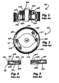
Figures 2-5 illustrate a prior art backspin retarder according to Canadian patent application2,311,036 . More particularly, -
Fig. 2 is a cross-sectional view of the centrifugal backspin retarder; -
Fig. 3 is a plan view according toFig, 2 ; -
Fig. 4 is a partial cross-sectional view according toFig. 2 in an engaged position; and -
Fig. 5 is a partial cross-sectional view according toFig. 2 in a disengaged position; and -
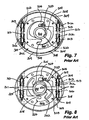
Figures 6 - 8 illustrate a prior art backspin retarder according toUS patent 6,079,489 . More particularly, -
Fig. 6 is a longitudinal cross-sectional view illustrating the prior art backspin retarder; -
Fig. 7 is a cross-sectional view according toFig. 6 , the retarder in an inactive or disabled position; and -
Fig. 8 is a cross-sectional view according toFig. 6 , the retarder in an active or braking position; -
Figure 9 is a cross sectional side view of an embodiment of the invention; -
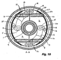
Figure 10 is top sectional view along section lines A-A according toFig. 9 and in an embodiment of the invention, the upper hub flange removed and the cam engagement slots illustrated in dotted lines to show the cam follower extending axially from the brake shoes in a non-rotating position; -
Figure 11 is a plan view according toFig. 9 illustrated in a disengaged, disabled position; -
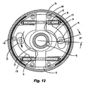
Figure 12 is a plan view according toFig. 9 in an engaged position braking; -
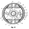
Figure 13 is a plan view according toFig. 9 and in an embodiment of the invention, an outer cam engaging surface being discontinuous, the brake shoes illustrated in a disengaged, disabled position; -
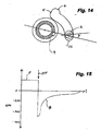
Figure 14 is a partial plan view according to an embodiment of the invention illustrating an angle between the cam follower and the shaft permitting increased brake multiplier effects; -
Figure 15 is a graphical representation illustrating a desired dissipation of energy from a rod string; -
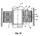
Figure 16 is a cross sectional side view along section lines B-B of an embodiment of the invention wherein the hub has a central flange; -
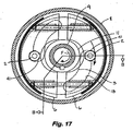
Figure 17 is a plan view according toFig. 16 ; -
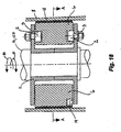
Figure 18 is a cross sectional side view of an embodiment of the invention wherein the cam surfaces are formed in the brake shoes and the cam followers extend from the hub for engagement therewith; -
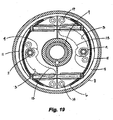
Figure 19 is a top sectional view according toFig. 18 ; and -
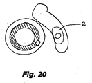
Figure 20 is a partial plan view according to an embodiment of the invention illustrating a profiled cam follower. - As shown in
Figs. 9-20 , embodiments of the invention provide improvements to prior art centrifugal braking systems. In one embodiment the backspin retarder or braking system 1 comprises acam follower 2 and at least acam surface 3 for actuatingbrake shoes 6 to an engaged braking position. The cam surface can have apocket 4 formed at a radiallyinward end 5 of thecam surface 3 for centrifugally engaging thecam follower 2 therein for maintaining the brake shoes in a disengaged position during normal operation and further, for preventing premature actuation of the braking system 1, such as during a rapid deceleration while still rotating in a forward direction (F). Thus,brake shoes 6 housed within the brake system 1 are permitted to move radially outward to an outward disengaged position under normal forward rotation F at operating speeds wherein thebrake shoes 6 do not engage a braking lining 7 with thehousing 8. For the purposes of illustration, a forward direction F is clockwise when viewed in plan, such asFig. 10 . - Preferably, the
cam follower 2 further comprisesanti-friction members 26, such as rolling friction bearings. - Further, as shown in
Figs. 12 and14 , thecam follower 2 is movable along at least thecam surface 3 for engaging thebrake shoes 6 in an engaged or braking position in a backspin direction B, such that a high brake multiplier effect is permitted before self locking occurs. An angle σ defined by a line drawn through a center of adrive shaft 9 and a point of contact 10 of thecam follower 2 with the innercam engagement surface 3, and a line drawn between the point of contact 10 and the center of the rollingcam follower 2 is less than 90°. In an embodiment of the invention the angle σ is about 15°. - While the following disclosure is primarily directed toward application of a centrifugal braking system for a wellhead drive and particularly to prevent backspin therein, embodiments of the invention may be applied to other applications, including but not limited to a centrifugal clutch, a centrifugal brake, a one-way engagement system, an engagement system for a dutch or brake, and other general applications where it might be applied by one skilled in the art.
-
Fig.1 illustrates a known typical progressive cavity pump (PCP)installation 101. Theinstallation 101 includes a progressing cavity pump wellhead drive 102, a prime mover, in this case anelectric motor 103, a belt andsheave drive system 104, all of which are mounted on a blow out preventor (BOP) 105 with an integral flow tee, generally known as a BOP/flow tee. The BOP/flow tee is mounted on awellhead 106. The wellhead drive 102 supports and drives adrive shaft 107, generally known as a "polished rod". Thepolished rod 107 is supported and rotated by means of a polished rod damp 108, which engages anoutput shaft 109 of the wellhead drive 102 by means of milled slots (not shown) in both parts. Thepolished rod 107 drives arod string 110, which in turn, drives a rotor, 111, inside a stator, 112. The rotor and stator 111,112 together are called the progressive cavity pump (PCP). Theelectric motor 103 is typically controlled from acontrol panel 113, which typically uses an on-off switch or alternatively, a variable frequency drive (VFD). Thestator 112 of thePCP 101 is connected to theproduction tubing 115 which extends into a wellbore. Casing 116 is cemented into the wellbore drilled in theformation 117, thecasing having perforations 118 which fluidly connect the wellbore, with the producingformation 117. The distance between a top of thewellhead 106 and fluid inside anannulus 119 between theproduction tubing 115 and thecasing 118 is called the fluid level. - In operation, the wellhead drive 102 rotates in a forward direction until the
prime mover 103 shut down. Torque applied to therod string 110 causes therod string 110 to store elastic energy in the form of strain energy in therod string 110. Additional energy is stored in the form of potential energy in the produced fluid due to the difference between a fluid height at the wellhead drive 102 and the fluid level in theannulus 119 between theproduction tubing 115 and thecasing 116. As soon as theprime mover 103 is shut down, there is no longer torque applied by the wellhead drive 102 in the forward direction. However, rod torque due to strain energy in therod string 110 causes therod string 110 and the wellhead drive 102 to quickly slow down and then rotate in a reverse or backspin direction. Further, as the fluid level equalizes between theannulus 119 and the inside of thetubing string 115, the fluid drives thepump rotor 11 in reverse and additional energy is imparted into therod string 110. Generally a backspin brake is built into the wellhead drive 102 to retard the backspin speed and absorb and dissipate the energy. The present invention is directed toward a braking system built which is particularly suited for use in the wellhead drive 102 of such a PCP installation. - Applicant has previously provided centrifugal braking solutions as shown in Canadian patent application
2,311,036, filed June 9, 2000 and shown herein atFigs. 2-5 . The prior artcentrifugal brake assembly 201 is comprised of adriving hub 202 and an alternately drivenhub 203. The drivinghub 202 is non-rotatably connected to theinput shaft 204. The drivenhub 203 is mounted for alternating free or driven rotation on the input shaft by anupper roller bearing 205 and a lowerthrust bearing assembly 206. - One end of each of a pair of brake shoes 207 are pivotally connected to the driven hub by pivot pins 208. A pin 209 on the other end of each of one brake shoe is connected to an adjacent pivot 210 of the other brake shoe by a
helical tension spring 211 so as to bias the brake shoes 207 radialy inwardly toward respective unlocked positions.Brake linings 212 are secured to the outer arcuate sides of the brake shoes 207 for frictional engagement with theinner surface 213 of adrive head housing 214. - One end of each brake shoe 207 is fixed to the driven
hub 203 by means of one of the pivot pins 208. The other end of each brake shoe 207 is free to move inwardly. The driving and driven hubs 202,203 are formed with respective grooves 215,216 in adjacent surfaces 217,218 for receivingdrive balls 219, of which only one is shown. Thegroove 215 in thedriving hub 202 is formed with a ramp or sloped surface 220 which terminates in aball chamber 221 in which thedrive ball 219 is located when thedrive shaft 204 rotates in a forward direction. Centrifugal force holds thedrive ball 219 radially outward and upward in theball chamber 221 so there is no ball motion or contact with the drivenhub 203 while rotation of the drivinghub 202 is rotating in the forward direction (Fig. 5 ). When thedrive shaft 204 rotates in a reverse direction (Fig. 4 ), thedrive ball 219 moves downward to a position in which it engages and locks both hubs 202,203 in together and the drivinghub 202 rotationally drives the drivenhub 203. - When the drive head starts to turn, the
drive ball 219 rests on the drivenhub 203 and thedrive ball 219 rides up the ramp 220. As the speed increases, thedrive ball 219 jumps slightly above the ramp 220 and is thrown up into theball chamber 221, where it is held by centrifugal force. When the electric motor turning the drive head is shut off, the drive head stops and thedrive ball 219 drops into thegroove 216 in the drivenhub 203. The spherical surface of the drivinghub 202 wedges thedrive ball 219 against the spherical surface of the drivenhub 203 thus starting the brake shoes 207 turning. - The reverse ramp of the driving
hub 202 serves an important function associated with the centrifugal brake. Thecentrifugal brake 201 has no friction against thehousing 214 until thebrake 201 turns fast enough to overcome the brake retraction springs 211. If the drivinghub 202 generates impact against the drivenhub 203 during engagement, the drivenhub 203 can accelerate away from the drivinghub 202. If the drivinghub 202 is turning fast enough, thedrive ball 219 will rise up into theball chamber 221 and stay there. By adding a reverse ramp, thedrive ball 219 cannot rise up during impact and since the ramp is relatively long, it allows the drivinghub 202 to catch up to the drivenhub 203 and keep thedrive ball 219 down where it can wedge between the driving and driven hubs 202,203. - Further, as shown in
Figs. 6-8 , and as extracted from Applicant's issued patentUS 6,079,489 , acentrifugal brake mechanism 300 acts directly on abrake housing 301. The prior art embodiment provides abackspin retarder 302 having two or more weightedmovable brake members 303 which are biased toward an inner inactive or disabled position, and which, during forward rotation of the drive shaft, are retained in the inner position and which, during reverse rotation of the drive shaft, are permitted to move radially outwardly under the influence of centrifugal force towards and in engagement withhousing 301, which serves as a stationary brake member. In addition, during reverse rotation, means are provided for urging the movable brake members into more intimate contact with the stationary brake member.Retarder 302 is seen to be comprised of a pair of opposed, movable brake members orbrake shoes 303, a brake actuator, generally designated byreference numeral 304, and astationary brake member 305, which in this embodiment, is the inner surface of thehousing 301. - The prior
art brake members 303 are axially supported by anannular support plate 308 mounted on bearingspacer 307. Thesupport plate 306 is preferably made of a bearing material to prevent galling of the brake shoes and serves as a rotatable bearing for the bearingspacer 307. The function of theshoe support plate 306 is to support theshoes 303 such that they do not vertically rest on thebrake actuator 304 so that, in turn, the inertia of theshoes 303 will tend to hold theshoes 303 in position while theactuator 304 rotates from the forward, disengaged direction to the reverse, engaged direction. Thebrake shoes 303 are generally semi-circular in shape and having abrake lining 308 affixed to their respective outer circular faces 309 for engagement with the inner surface of thehousing 302. - The prior
art brake shoes 303 are radially movable with respect to the axis ofshaft 310 between an inner, retracted position shown inFig. 7 and an outer braking position shown inFig. 8 . The generally planar,inner edges 311 of the brakes shoes 303 abut one another in the retracted position to limit the degree of travel, balance theshoes 303 during forward rotation and reduce oil-circulation in this non-braking position. Thebrake shoes 303 are biased towards the inner, retracted position by compression springs 312. To that end, eachbrake shoe 303 is formed withholes 313 which open into inner edges 314 and which parallel the direction of movement of thebrake shoes 303. Theholes 313 include a reduceddiameter portion 315 defining anannular shoulder 316. Theholes 313 are aligned as shown to receive aspring retaining rod 317. Thesprings 312 are telescopically mounted on the opposite ends of therod 317 with their inner ends bearing againstshoulder 316 and their outer ends bearing against awasher 318 and jam nuts 319. In the absence of centrifugal force sufficient to overcome the force of thesprings 312, thesprings 312 will urge thebrake shoes 303 towards their inner, retracted positions shown inFig. 7 .Brake actuator 304 has two primary roles. The first is to positively retain thebrake shoes 303 in their retracted positions during forward rotation of thedrive shaft 310 which, inFigs. 7 and 8 , is in the clockwise direction. The second role of theactuator 304 is to urge thebrake shoes 303 into more intimate contact with thestationary brake member 305 during reverse rotation of theshaft 310 by applying an additional radial outward force against thebrake shoes 303. - The
prior art actuator 304 is formed with acylindrical hub 321 having akeyway 322 for receiving a key 323 formed in theshaft 310. Thus, theactuator 304 rotates with theshaft 310. Theactuator 304 is further formed with a pair of opposed, latchingfingers 324, one finger associated with eachbrake shoe 303. The latchingfingers 324 are bifurcated to receive aportion 325 of reduced thickness of thebrake shoes 303 which define latchingfinger cavities 327 andprojection 328. Thecavities 327 receive the end of a latchingfinger 324 for
interlocking theactuator 304 andbrake shoes 303 during forward rotation. In addition, the latchingfingers 324 are each formed with acam surface 329 on the side thereof remote from the axis of theshaft 310. When theshaft 310 rotates in a counter-clockwise backwards direction, the cam surfaces 329 act upon planar surfaces 331 of thebrake shoes 303 and thereby urges thebrake shoes 303 radially apart towards and into engagement with thestationary brake member 305. Finally, for resetting theshoes 303, the underside of the tips of the latchingfingers 324 are formed with achamfer 332 which engage the tips ofprojections 328 and guide the tips of the fingers intocavities 327 when theshaft 310 is restarted in a forward direction so as to ensure that an interlock is achieved. In operation, when theshaft 310 is rotated in a forward direction, the tips of the latchingfingers 324enter cavities 327 and thereby not only prevent reverse rotation of thebrake shoes 303, but retain theshoes 303 in their radially inner, disabled positions and cause theshoes 303 to rotate with theactuator 304 and theshaft 310. If, for any reason, theshaft 310 is caused to rotate in reverse, theactuator 304 will rotate in a counter-clockwise direction with respect to thebrake shoes 303 and disengage theshoes 303. This will free thebrake shoes 303 to move radially outwardly under centrifugal force towards and into engagement with thestationary brake surface 305. Further, the cam surfaces 329 apply a radial outward force to surfaces 331 of thebrake shoes 303 in addition to the centrifugal force. Thecams 329 press radially outward while applying tangential (torque) loading to theshoes 303. The radial component of the cam force puts more pressure on thebrake shoes 303 and thereby provides more torque than a device which depends only on centrifugal force. Thebrake retarder 301 provides a brake disengagement mechanism, rather than a brake engagement mechanism, so that thebrake 300 is deactivated while operating in the forward direction. This means there is no brake engaging device which could fail to engage and, thus, the brake reliability is enhanced. Thebrake 300 is activated automatically as soon as theshaft 310 begins to rotate in reverse, subject only to the spring force of thesprings 312. As with the previous embodiment, thesprings 312 will resist braking until a predetermined safe shaft speed. Unfortunately, Applicant'sprior art retarder 301 is vulnerable to sudden changes in the angular momentum of theactuator 304 and can prematurely actuate. - As show in
Figs, 9-17 , embodiments of the present centrifugal backspin retarder or braking system 1 comprise a cam arrangement, more particularly in this embodiment, eachcam follower 2 extends axially outward from thebrake shoe 6 to engage acam surface 3 formed in abrake hub 11. The cam arrangement acts between thehub 11 and thebrake shoes 6 for actuating thebrake shoes 6 between the disengaged and engaged positions. As previously described, thecam follower 2 preferably comprises anti-friction members, such as rollingelements 26, typically roller bearings. Due to the rollingelements 26, the friction coefficient is very low and due to the angle σ as described above and shown inFig. 16 , much higher brake multiplier effects can be achieved without locking up. A limiting factor of the braking is the strength of the connection between thecam follower 2 and thebrake shoe 6 since a radial force is substantially higher than a tangential braking force due to geometry. A brake multiplier effect of 3.5 or higher can be achieved without locking up the braking system 1 and with application of safe loads on thecam follower 2. In embodiments of the invention the brake multiplier effect ranges from about 3.5 to about 5. Embodiments of the invention make it possible to provide much greater braking force within the same brake drum diameter and length and permit manufacture of much smaller systems, lowering the weight and cost of the wellhead drive and making the drive easier to install. Preferably, the two ormore cam followers 2 are substantially circular. Alternately, as shown inFig. 20 , the two ormore cam followers 2 may be profiled, such as ovoid or kidney shaped. The profiled follower can pivot. - An embodiment of the invention is shown in
Figs. 9-12 . The backspin retarder 1 comprises thebrake hub 11 having two or morecam engagement slots 12 formed therein and distributed circumferentially thereabout, each cam engagement slot further comprising thecam surface 3 and anouter guiding surface 13 for directing thebrake shoes 6 between an engaged position (Fig. 12 ) for braking when rotated backwards B, such as under backspin, a disengaged position (Fig. 10 ) at rest, and an outward disengaged position (Fig. 11 ) when rotated in a forward direction F at operating speeds for preventing premature engagement. - Each of two or
more cam followers 2 comprises a rolling anti-friction bearing or rolling element and extends axially outward from each of thebrake shoes 6 for engaging eachcam engagement slot 12. The two ormore cam followers 2 permit a higher multiplier of centrifugal effect to provide more torque which enables the use of a smaller brake drum diameter as desired, than would be possible with the prior art. Thebrake shoes 6 are supported axially in thebrake hub 11 by antifriction means 14, such as rolling friction bearings or ball transfers, to ensure engagement even under very low acceleration conditions which may occur after the use of variable frequency drive (VFD) braking. Other anti-friction surfaces could be employed. - More particularly, and having reference to
Fig. 9 , the brake 1 comprises the housing orgear case 8 having the mainrotatable shaft 9 extending therethrough. Thebrake hub 11 is supported for co-rotation with themain shaft 9 and thebrake shoes 6 are supported on thebrake hub 11. Theshaft 9 may be a generic shaft in ahousing 8 that requires a clutch or brake arrangement or may be thehollow shaft 9 supporting thepolished rod 107, such as shown InFig. 1 . - With reference to
Figs. 9-12 , twobrake shoes hub 11. Optionally,additional brake shoes 6, such as three or four (not shown), may be used being circumferentially distributed about thehub 11. Thehub 11 supports upper and a lowerradial flanges 15,16.Brake shoes flanges 15,16. The upper and lowerradial flanges 15,16 can incorporate the two or morecam engagement slots 12. Preferably the two or morecam engagement slots 12 are mirrored axially in the upper andlower flanges 15,16. - Each
brake shoe 6 further comprises a brake shoe body 17 incorporatingcam followers cam engagement slots radial flanges 15, 16 respectively. Eachbrake shoe 6 has a brake pad or lining 18 which engages thehousing 8 when the brake 1 is in the engaged braking position. Thebrake shoes brake hub 11 by the rollingfriction bearings 14 positioned between theshoes radial flange 16. - Having reference to
Fig. 10 , thebrake shoes cam followers inward cam surface 3 of thecam engagement slot 12. The brake shoes are biased to the disengaged position by biasingmeans 19, such as conventional springs, which are connected thereto bytie bolts 20 extending throughtie bolt slots 21 and secured withwashers 22 and lock nuts 23. Little or no centrifugal forces are present. - The
cam engagement slot 12 comprises the radiallyinward end 5 and a radiallyoutward end 24. - In operation, as first shown and discussed for
Fig. 10 , when theshaft 9 is rotated slowly in a forward direction, thebrake shoes cam followers cam follower 2 being positioned adjacent thecam surface 3 of theslot 12. - As shown in
Fig. 11 , as the rotation increases to normal operating revolutions per minute (rpm), thebrake shoes pocket 4 is formed at the radialinward end 5 of eachcam engagement slot 12 and extends radially outward therefrom for engaging thecam follower 2 and eachbrake shoe 6 in an outward disengaged position. Eachbrake shoe 6 andcorresponding cam followers cam follower 2 engages eachpocket 4. Thebrake shoes pocket 4 arrests further outward movement of thebrake shoes brake lining 18 andhousing 8 while permitting thebrake shoes hub 11 and theshaft 9 In the forward direction F. Further, thepocket 4 forms alip 25 which acts to retain thecam follower 2 in thepocket 4 in instances of abrupt deceleration and changes in angular momentum, which are essentially equivalent to a weak "backspin", which would otherwise, as in the case with the prior art devices, cause eachcam follower 2 to move along thecam surface 3 and permit thebrake shoes housing 8. The height of thelip 25 is preferably less than a radius of thecam follower 2 to enable thecam follower 2 to readily actuate during backwards rotation. - As shown in
Fig. 12 , when theshaft 9 is slowed, stopped and then is caused to rotate backwards, such as when a PCP is turned off and the rod string is permitted to controllably release stored energy, thehub 11 co-rotates with the shaft in a counter-clockwise, backwards direction B with respect to thebrake shoes hub 11 transitions from forward F to backwards B rotation, eachcam follower 2 is biased to disengage from eachpocket 4 and enter eachslot 12. During the backspin, centrifugal force drives thebrake shoes cam followers cam surface 3 of thecam engagement slots 12. Backwards rotation B of thehub 11 andslot 12, drives thecam followers 2 to move toward the radiallyoutward end 24 of theslot 12, forcing thebrake shoes brake lining 18 with thehousing 8. Thereafter, thecam engagement slots 12 continue to drive thecam followers brake shoes 6 and lining 18 into engagement with thehousing 8 proportional to the centrifugal force. Due to the angle σ of thecam follower 2 relative to theshaft 9, brake multiplier effects in the order of about 3.5 to about 5 are applied without locking up of the brake system 1 and permitting desired dissipation of the stored energy in the rod string orshaft 9. Theouter guiding surface 13 can aid in proper alignment of thecam follower 2 with thecam surface 3 and return to thepocket 4 as the braking system moves from the engaged braking position to the rest position or disabled position. This may be of particular importance if the PCP is turned off and then turned on again before the shaft and hub have stopped rotating and stored energy has been dissipated. - Having reference to
Fig. 13 , and in an embodiment of the invention, the outer guidingsurface 13 is a discontinuous surface comprising aramp 30 formed adjacent thepocket 4 for aiding in re-engagement of thecam follower 2 with thecam surface 3 and thepocket 4. In this embodiment theshaft 9 must be permitted to come to a stop before restarting rotation In the forward direction F to prevent improper engagement of thecam follower 2 with theramp 30, which may prevent engagement of thecam follower 2 with thepocket 4. Failure to properly engage thecam follower 2 with the pocket results in an inability of thebrake shoes - Having reference to
Figs. 16 and17 , and in an embodiment of the invention, thehub 11 is formed having acentral flange 40 rather than upper andlower flanges 15, 16. In this embodiment, thebrake shoes 6 are supported around thecentral flange 40. Acam engagement slot 12 is formed in thecentral flange 40 and acam follower 2 is supported in thecam engagement slot 12, such as by afastener 41, which extends between upper and lower brake shoe surfaces 42,43. Thebrake shoes central flange 40 by anti-friction means 14, such as rolling anti-friction bearings. - Having reference to
Fig. 15 , in normal pumping operation, thehub 11 can rotate at typical speeds of between 50 and 200 rpm. As shown, when the pump is turned off, the forward rotation F quickly reverses to a backwards rotation B as the energy of the sucker rods is released. The centrifugal force restrains the backspin to about 500-700 rpm and diminishes as the energy is dissipated. Further, as the hydraulic head of fluid in the production tubing diminishes, the backwards rotation B diminishes also to 0 rpm. - As one of skill In the art will appreciate, and as shown in
Figs. 18 and19 , thecam surface 3 orcam engagement slot 12 can be formed in thebrake shoes cam followers 2 can extend from thehub 11 for engagement therewith. In order to actuate thebrake shoes 6 between the disengaged and engaged position thepocket 4 is formed at the radiallyoutward end 24 ofslot 12 and thepocket 4 extends radially inwardly.
Claims (16)
- A brake system (1) for retarding backspin comprising:a main rotatable shaft (9) extending axially through a brake housing (8);a hub (11) supported for co-rotation by the shaft (9) and rotatable concentrically in the brake housing (8);two or more brake shoes (6) distributed circumferentially about the hub (11), each brake shoe (6) movable radially between a biased, radially inward disengaged position, the brake shoes (6) retained thereat when the shaft (9) rotates in a forward direction, and an engaged position in braking engagement with the brake housing (8), when the shaft (9) rotates in a backwards direction;a cam arrangement (2,12) acting between the two or more brake shoes (6) and the hub (11) comprising:two or more arcuate cam surfaces (3) extending circumferentially between a radially inward end (5) and a radially outward end (24);and two or more cam followers (2), each cam follower (2) operatively engaging each cam surface (3) for actuating the brake shoes (6) between the disengaged position in the forward direction and the engaged position in the backward direction
characterized by:a radially extending pocket (4) formed in each of the two or more arcuate cam surfaces (3) wherein each brake shoe (6) is centrifugally retained in the disengaged position within the radially extending pocket (4). - The brake system (1) of claim 1 wherein when the shaft (9) transitions between the forward direction and the backward direction, the brake shoes (6) bias inwardly and each cam follower (2) engages each cam surface (3) at the disengaged position.
- The brake system (1) of claim 1 or 2 wherein the two or more cam surfaces (3) are formed on the hub (11) and the two or more cam followers (2) extend axially outwardly from the two or more brake shoes (6).
- The brake system (1) of claim 1, 2 or 3 further comprising two or more cam slots (12) comprising the two or more cam surfaces (3) and two or more substantially parallel guiding surfaces (13).
- The brake system of claim 4 wherein each substantially parallel guiding surface (13) is discontinuous and further comprises:a ramp (30) positioned adjacent the radially extending pocket (4) for guiding each cam follower (2) to the disengaged position.
- The brake system (1) of any one of claims 1-5 wherein each cam follower (2) further comprises anti-friction members (26), each cam follower (2) and each cam surface (3) forming a cam angle sufficient to provide a brake multiplier greater than 3.5.
- The brake system (1) of any one of claims 1 to 6 wherein the brake hub (11) further comprises:a central tubular conduit through which the main driven rotatable shaft (9) extends; anda hub flange (40) extending radially outward from the central tubular conduit for supporting the brake shoes (6) thereon, wherein the cam arrangement (2,12) acts between the brake shoes (6) and the hub flange (40).
- The brake system (1) of any one of claims 1 to 6 wherein the hub (11) further comprises upper (15) and lower (16) hub flanges, the two or more circumferentially distributed brake shoes (6) being supported there between, wherein the two or more cam surfaces (3) are circumferentially distributed about each of the upper and lower hub flanges (15,16); and
the two or more cam followers (2) extend axially from a top and a bottom surface (42,43) of each of the circumferentially distributed brake shoes (6) for engaging the two or more cam surfaces (2). - The brake system (1) of claim 8 wherein the radially extending pocket (4) is a radially outwardly extending pocket (4) formed at the radially inward end (5) of each cam surface (3).
- The brake system (1) of claim 9 wherein each radially outwardly extending pocket (4) forms a lip (25) for retaining each cam follower (2) therein.
- The brake system (1) of any one of claims 1 to 6 wherein the hub (11) further comprises upper and lower hub flanges (15,16), the two or more circumferentially distributed brake shoes (6) being supported there between, wherein the two or more cam surfaces (3) are circumferentially distributed about each of the two or more circumferentially distributed brake shoes (6);
the radially extending pocket is a radially inwardly extending pocket (4) formed at the radially outward end (24) of each cam surface (3); and
the two or more cam followers (2) extend axially from the upper and lower hub flanges (15,16) for engaging the cam surfaces (3). - The brake system (1) of any one of claims 1 to 11 wherein the circumferentially distributed brake shoes are axially supported on the hub by anti-friction means.
- The brake system (1) of any one of claims 1 to 12 wherein the two or more cam followers (2) further comprise anti-friction members (26) for engaging the cam surface (3).
- A method for retarding backspin in a brake system (1) having a main rotatable shaft (9) extending axially through a brake housing (8), a hub (11) supported for co-rotation by the shaft (9) and rotatable concentrically in the brake housing (8) and two or more brake shoes (6) distributed circumferentially about the hub (11), the method comprising:biasing the brake shoes (6) inwardly to the hub (11);rotating the hub (11) in a forward direction to centrifugally overcome the biasing and actuate the brake shoes (6) to an outward disengaged position;centrifugally retaining the brake shoes (6) at a radially extending pocket (4) in the outward disengaged position during rotation in the forward direction;slowing rotation of the hub (11) in the forward direction to transition to rotation in a backward direction causing biasing of the brake shoes (6) inwardly from the pocket (4);rotating the hub (11) in the backward direction; andactuating the brake shoes (6) to the engaged position by camming the brake shoes (6) outwardly to engage the housing (8) during the rotation in the backward direction.
- The method of claim 14 wherein the camming further comprises driving a cam follower (2), operatively connected to the brake shoes (6), circumferentially and radially outwardly to the engaged position in the backward direction.
- The method of claim 14 further comprising guiding the cam follower (2) circumferentially and radially to the disengaged position in the forward direction.
Applications Claiming Priority (2)
| Application Number | Priority Date | Filing Date | Title |
|---|---|---|---|
| CA002530782A CA2530782A1 (en) | 2005-12-14 | 2005-12-14 | Cam actuated centrifugal brake for wellhead drives |
| PCT/CA2006/002044 WO2007068118A1 (en) | 2005-12-14 | 2006-12-14 | Cam-actuated centrifugal brake for preventing backspin |
Publications (3)
| Publication Number | Publication Date |
|---|---|
| EP1969246A1 EP1969246A1 (en) | 2008-09-17 |
| EP1969246A4 EP1969246A4 (en) | 2009-09-09 |
| EP1969246B1 true EP1969246B1 (en) | 2012-01-25 |
Family
ID=38162377
Family Applications (1)
| Application Number | Title | Priority Date | Filing Date |
|---|---|---|---|
| EP06840471A Active EP1969246B1 (en) | 2005-12-14 | 2006-12-14 | Cam-actuated centrifugal brake for preventing backspin |
Country Status (7)
| Country | Link |
|---|---|
| US (1) | US9027717B2 (en) |
| EP (1) | EP1969246B1 (en) |
| AT (1) | ATE543020T1 (en) |
| AU (1) | AU2006324285B2 (en) |
| CA (1) | CA2530782A1 (en) |
| EA (1) | EA014039B1 (en) |
| WO (1) | WO2007068118A1 (en) |
Families Citing this family (23)
| Publication number | Priority date | Publication date | Assignee | Title |
|---|---|---|---|---|
| BRPI0605236A (en) * | 2006-12-06 | 2008-07-22 | Weatherford Ind E Com Ltda | remote braking system |
| BRPI0605759A (en) * | 2006-12-15 | 2008-08-12 | Weatherford Ind E Com Ltda | auxiliary brake for drive heads for progressive cavity pumps |
| US8662186B2 (en) | 2011-03-15 | 2014-03-04 | Weatherford/Lamb, Inc. | Downhole backspin retarder for progressive cavity pump |
| CN102562886B (en) * | 2012-01-20 | 2014-12-17 | 望安辉 | Safety brake device of oil pumping unit |
| CN102865227B (en) * | 2012-10-16 | 2014-12-10 | 北京世通华奥油田化学技术有限公司 | Automatic braking force regulating device for screw oil pump |
| EP2725253A3 (en) * | 2012-10-26 | 2017-11-01 | Kudu International Inc. | Centrifugal backspin brake |
| US9506545B2 (en) | 2013-03-15 | 2016-11-29 | John W. Klovstadt | Continuously variable transmission having a periodic displacement waveform with a constant velocity portion |
| FR3012184B1 (en) * | 2013-10-17 | 2015-12-11 | Clyde Union S A S | CENTRIFUGAL MOTOR PUMP FOR PRIMARY CIRCUIT FOR SMALL OR MODULAR NUCLEAR REACTOR MEANS. |
| US20150308218A1 (en) * | 2014-04-28 | 2015-10-29 | Baker Hughes Incorporated | Extrusion gap reduction device and method for reducing an extrusion gap |
| US9441683B2 (en) * | 2014-06-17 | 2016-09-13 | Yen-Hong Wong | Hydraulic auxiliary brake device of motor used for oil production |
| US9568053B2 (en) * | 2014-08-19 | 2017-02-14 | Brightling Equipment Ltd. | Method and apparatus for limiting rotation of a drive shaft in a reverse direction |
| US10981760B2 (en) | 2014-10-07 | 2021-04-20 | Skysaver Rescue Ltd. | Centrifugal brake mechanism |
| IL235049A (en) * | 2014-10-07 | 2017-05-29 | Skysaver Rescue Ltd | Centrifugal brake |
| DE202015000702U1 (en) * | 2015-01-30 | 2016-05-04 | Solo Kleinmotoren Gmbh | Moment-controlled braking device for driven tools |
| MX2019004477A (en) * | 2016-10-17 | 2019-10-09 | Risun Oilflow Solutions Inc | Sealing/locking rod safety clamp and ram system. |
| US11018610B2 (en) | 2017-01-27 | 2021-05-25 | Franklin Electric Co., Inc. | Motor drive system and method |
| CA2967606C (en) | 2017-05-18 | 2023-05-09 | Peter Neufeld | Seal housing and related apparatuses and methods of use |
| US10208816B2 (en) | 2017-05-23 | 2019-02-19 | Teco-Westinghouse Motor Company | Anti-reverse rotation apparatuses, rotors for use therein, and related methods |
| CN109114130A (en) * | 2018-08-09 | 2019-01-01 | 宁波华表机械制造有限公司 | A kind of drum brake formula bidirectional automatic clutch |
| RU2693118C1 (en) * | 2018-11-28 | 2019-07-01 | Общество С Ограниченной Ответственностью "Оклэс Технолоджиз" | Device for prevention of turbine rotation |
| US11598382B2 (en) | 2019-07-12 | 2023-03-07 | Pella Corporation | Adaptive centrifugal brake assemblies |
| CA3230462A1 (en) * | 2021-09-03 | 2023-03-09 | Zheng Ye | Auto-engageable coupling for preventing transmission of reverse rotation to esp motors |
| CN117386742A (en) * | 2023-11-22 | 2024-01-12 | 中国石油天然气集团有限公司 | Damping device for rotating shaft |
Family Cites Families (23)
| Publication number | Priority date | Publication date | Assignee | Title |
|---|---|---|---|---|
| US1749624A (en) * | 1928-02-13 | 1930-03-04 | Jonas W Batson | Brake mechanism |
| US1908228A (en) * | 1931-04-30 | 1933-05-09 | Dotson Leroy | Automotive brake |
| US2072852A (en) * | 1935-01-10 | 1937-03-09 | Twin Disc Clutch Co | Clutch |
| US2268605A (en) * | 1939-09-01 | 1942-01-06 | Mattersdorf Gustav | Friction brake |
| US2547864A (en) * | 1948-06-11 | 1951-04-03 | Whizzer Motor Company | Coaster brake |
| US3432013A (en) * | 1966-07-05 | 1969-03-11 | Shimano Industrial Co | Rear hub with built-in three stage speed change mechanism for a bicycle |
| US3485109A (en) * | 1968-06-24 | 1969-12-23 | Laurel E Dunlap | Backlash brake for gear drive |
| US4144853A (en) * | 1972-04-28 | 1979-03-20 | Nissan Motor Company, Limited | Ignition timing control change-over system |
| US4134481A (en) * | 1974-12-09 | 1979-01-16 | Calderazzo Franklin J | Back-pedal brake operator and braking system for multi-speed bicycles |
| US4144953A (en) * | 1977-05-09 | 1979-03-20 | Loffland Brothers Company | Rotary drive disc brake for drawworks |
| US4797075A (en) * | 1987-04-09 | 1989-01-10 | Hughes Tool Company | Overspeed protective gear box for a well pump |
| US5027930A (en) * | 1989-01-23 | 1991-07-02 | Hess-Reed Partners | Coaster brake assembly |
| US4981200A (en) * | 1989-08-25 | 1991-01-01 | Eaton Corporation | Brake having anchor bearing on immovable spider |
| CA2074013A1 (en) | 1992-07-16 | 1994-01-17 | Robert A. R. Mills | Brake assembly for rotating rod |
| JP3638309B2 (en) * | 1994-06-23 | 2005-04-13 | 株式会社シマノ | Bicycle hub brake |
| US5551510A (en) * | 1995-03-08 | 1996-09-03 | Kudu Industries Inc. | Safety coupling for rotary down hole pump |
| GB2299849A (en) | 1995-04-10 | 1996-10-16 | Mono Pumps Ltd | Downhole pump drive head assembly with hydrodynamic retarder |
| US5673773A (en) * | 1996-01-16 | 1997-10-07 | Valisum Industries Ltd. | Structure of a drum brake for bicycles |
| US6079489A (en) * | 1998-05-12 | 2000-06-27 | Weatherford Holding U.S., Inc. | Centrifugal backspin retarder and drivehead for use therewith |
| JP2001159434A (en) * | 1999-12-01 | 2001-06-12 | Wakayama Nainenki Co Ltd | Emergency braking device |
| US6607465B1 (en) * | 2000-03-10 | 2003-08-19 | Shimano, Inc. | Bicycle hub transmission with a guiding member for a sun gear |
| US6290028B1 (en) * | 2000-05-09 | 2001-09-18 | Liu Jen-Chih | Bike brake |
| CA2311036A1 (en) | 2000-06-09 | 2001-12-09 | Oil Lift Technology Inc. | Pump drive head with leak-free stuffing box, centrifugal brake and polish rod locking clamp |
-
2005
- 2005-12-14 CA CA002530782A patent/CA2530782A1/en not_active Abandoned
-
2006
- 2006-12-14 US US12/095,984 patent/US9027717B2/en active Active
- 2006-12-14 AU AU2006324285A patent/AU2006324285B2/en active Active
- 2006-12-14 AT AT06840471T patent/ATE543020T1/en active
- 2006-12-14 EA EA200870035A patent/EA014039B1/en not_active IP Right Cessation
- 2006-12-14 EP EP06840471A patent/EP1969246B1/en active Active
- 2006-12-14 WO PCT/CA2006/002044 patent/WO2007068118A1/en not_active Ceased
Also Published As
| Publication number | Publication date |
|---|---|
| AU2006324285A1 (en) | 2007-06-21 |
| EA200870035A1 (en) | 2008-10-30 |
| ATE543020T1 (en) | 2012-02-15 |
| US9027717B2 (en) | 2015-05-12 |
| WO2007068118A1 (en) | 2007-06-21 |
| EP1969246A4 (en) | 2009-09-09 |
| CA2530782A1 (en) | 2007-06-14 |
| AU2006324285B2 (en) | 2011-09-08 |
| US20080296011A1 (en) | 2008-12-04 |
| EA014039B1 (en) | 2010-08-30 |
| EP1969246A1 (en) | 2008-09-17 |
Similar Documents
| Publication | Publication Date | Title |
|---|---|---|
| US9027717B2 (en) | Cam-actuated centrifugal brake for preventing backspin | |
| US6079489A (en) | Centrifugal backspin retarder and drivehead for use therewith | |
| US9334908B2 (en) | Centrifugal backspin brake | |
| US11994003B2 (en) | Fallback prevention valve apparatus, system and method | |
| US6039115A (en) | Safety coupling for rotary pump | |
| AU2012201318B2 (en) | Downhole backspin retarder for progressive cavity pump | |
| US9322238B2 (en) | Polish rod locking clamp | |
| CA2710783C (en) | Pump drive head with stuffing box | |
| US4299296A (en) | In-hole motor drill with bit clutch | |
| US20150376950A1 (en) | Downhole tool using a locking clutch | |
| GB2410760A (en) | Downhole motor with locking mechanism to engage surface drive | |
| CA2571209C (en) | Cam actuated centrifugal brake for preventing backspin | |
| US20150083541A1 (en) | Anti-stall mechanism | |
| AU2012355817B2 (en) | Circumferential cams for mechanical case running tool | |
| US6135740A (en) | Pump drive head backspin retarder | |
| US6564911B2 (en) | Braking assembly | |
| CA2859817C (en) | Method and apparatus for limiting rotation of a drive shaft in a reverse direction | |
| MX2008007311A (en) | Cam-actuated centrifugal brake for preventing backspin | |
| RU2352752C1 (en) | Mechanical anchor | |
| CN117386742A (en) | Damping device for rotating shaft |
Legal Events
| Date | Code | Title | Description |
|---|---|---|---|
| PUAI | Public reference made under article 153(3) epc to a published international application that has entered the european phase |
Free format text: ORIGINAL CODE: 0009012 |
|
| 17P | Request for examination filed |
Effective date: 20080714 |
|
| AK | Designated contracting states |
Kind code of ref document: A1 Designated state(s): AT BE BG CH CY CZ DE DK EE ES FI FR GB GR HU IE IS IT LI LT LU LV MC NL PL PT RO SE SI SK TR |
|
| A4 | Supplementary search report drawn up and despatched |
Effective date: 20090811 |
|
| 17Q | First examination report despatched |
Effective date: 20090904 |
|
| GRAP | Despatch of communication of intention to grant a patent |
Free format text: ORIGINAL CODE: EPIDOSNIGR1 |
|
| GRAS | Grant fee paid |
Free format text: ORIGINAL CODE: EPIDOSNIGR3 |
|
| GRAA | (expected) grant |
Free format text: ORIGINAL CODE: 0009210 |
|
| RAP1 | Party data changed (applicant data changed or rights of an application transferred) |
Owner name: OIL LIFT TECHNOLOGY INC. |
|
| AK | Designated contracting states |
Kind code of ref document: B1 Designated state(s): AT BE BG CH CY CZ DE DK EE ES FI FR GB GR HU IE IS IT LI LT LU LV MC NL PL PT RO SE SI SK TR |
|
| DAX | Request for extension of the european patent (deleted) | ||
| REG | Reference to a national code |
Ref country code: GB Ref legal event code: FG4D |
|
| REG | Reference to a national code |
Ref country code: CH Ref legal event code: EP |
|
| REG | Reference to a national code |
Ref country code: AT Ref legal event code: REF Ref document number: 543020 Country of ref document: AT Kind code of ref document: T Effective date: 20120215 |
|
| REG | Reference to a national code |
Ref country code: IE Ref legal event code: FG4D |
|
| REG | Reference to a national code |
Ref country code: DE Ref legal event code: R096 Ref document number: 602006027373 Country of ref document: DE Effective date: 20120322 |
|
| REG | Reference to a national code |
Ref country code: RO Ref legal event code: EPE |
|
| REG | Reference to a national code |
Ref country code: NL Ref legal event code: T3 |
|
| LTIE | Lt: invalidation of european patent or patent extension |
Effective date: 20120125 |
|
| PG25 | Lapsed in a contracting state [announced via postgrant information from national office to epo] |
Ref country code: LT Free format text: LAPSE BECAUSE OF FAILURE TO SUBMIT A TRANSLATION OF THE DESCRIPTION OR TO PAY THE FEE WITHIN THE PRESCRIBED TIME-LIMIT Effective date: 20120125 Ref country code: IS Free format text: LAPSE BECAUSE OF FAILURE TO SUBMIT A TRANSLATION OF THE DESCRIPTION OR TO PAY THE FEE WITHIN THE PRESCRIBED TIME-LIMIT Effective date: 20120525 Ref country code: BE Free format text: LAPSE BECAUSE OF FAILURE TO SUBMIT A TRANSLATION OF THE DESCRIPTION OR TO PAY THE FEE WITHIN THE PRESCRIBED TIME-LIMIT Effective date: 20120125 Ref country code: BG Free format text: LAPSE BECAUSE OF FAILURE TO SUBMIT A TRANSLATION OF THE DESCRIPTION OR TO PAY THE FEE WITHIN THE PRESCRIBED TIME-LIMIT Effective date: 20120425 |
|
| PG25 | Lapsed in a contracting state [announced via postgrant information from national office to epo] |
Ref country code: PT Free format text: LAPSE BECAUSE OF FAILURE TO SUBMIT A TRANSLATION OF THE DESCRIPTION OR TO PAY THE FEE WITHIN THE PRESCRIBED TIME-LIMIT Effective date: 20120525 Ref country code: PL Free format text: LAPSE BECAUSE OF FAILURE TO SUBMIT A TRANSLATION OF THE DESCRIPTION OR TO PAY THE FEE WITHIN THE PRESCRIBED TIME-LIMIT Effective date: 20120125 Ref country code: GR Free format text: LAPSE BECAUSE OF FAILURE TO SUBMIT A TRANSLATION OF THE DESCRIPTION OR TO PAY THE FEE WITHIN THE PRESCRIBED TIME-LIMIT Effective date: 20120426 Ref country code: FI Free format text: LAPSE BECAUSE OF FAILURE TO SUBMIT A TRANSLATION OF THE DESCRIPTION OR TO PAY THE FEE WITHIN THE PRESCRIBED TIME-LIMIT Effective date: 20120125 Ref country code: LV Free format text: LAPSE BECAUSE OF FAILURE TO SUBMIT A TRANSLATION OF THE DESCRIPTION OR TO PAY THE FEE WITHIN THE PRESCRIBED TIME-LIMIT Effective date: 20120125 |
|
| REG | Reference to a national code |
Ref country code: AT Ref legal event code: MK05 Ref document number: 543020 Country of ref document: AT Kind code of ref document: T Effective date: 20120125 |
|
| PG25 | Lapsed in a contracting state [announced via postgrant information from national office to epo] |
Ref country code: CY Free format text: LAPSE BECAUSE OF FAILURE TO SUBMIT A TRANSLATION OF THE DESCRIPTION OR TO PAY THE FEE WITHIN THE PRESCRIBED TIME-LIMIT Effective date: 20120125 |
|
| PG25 | Lapsed in a contracting state [announced via postgrant information from national office to epo] |
Ref country code: CZ Free format text: LAPSE BECAUSE OF FAILURE TO SUBMIT A TRANSLATION OF THE DESCRIPTION OR TO PAY THE FEE WITHIN THE PRESCRIBED TIME-LIMIT Effective date: 20120125 Ref country code: DK Free format text: LAPSE BECAUSE OF FAILURE TO SUBMIT A TRANSLATION OF THE DESCRIPTION OR TO PAY THE FEE WITHIN THE PRESCRIBED TIME-LIMIT Effective date: 20120125 Ref country code: SI Free format text: LAPSE BECAUSE OF FAILURE TO SUBMIT A TRANSLATION OF THE DESCRIPTION OR TO PAY THE FEE WITHIN THE PRESCRIBED TIME-LIMIT Effective date: 20120125 Ref country code: SE Free format text: LAPSE BECAUSE OF FAILURE TO SUBMIT A TRANSLATION OF THE DESCRIPTION OR TO PAY THE FEE WITHIN THE PRESCRIBED TIME-LIMIT Effective date: 20120125 Ref country code: EE Free format text: LAPSE BECAUSE OF FAILURE TO SUBMIT A TRANSLATION OF THE DESCRIPTION OR TO PAY THE FEE WITHIN THE PRESCRIBED TIME-LIMIT Effective date: 20120125 |
|
| PG25 | Lapsed in a contracting state [announced via postgrant information from national office to epo] |
Ref country code: SK Free format text: LAPSE BECAUSE OF FAILURE TO SUBMIT A TRANSLATION OF THE DESCRIPTION OR TO PAY THE FEE WITHIN THE PRESCRIBED TIME-LIMIT Effective date: 20120125 |
|
| PLBE | No opposition filed within time limit |
Free format text: ORIGINAL CODE: 0009261 |
|
| STAA | Information on the status of an ep patent application or granted ep patent |
Free format text: STATUS: NO OPPOSITION FILED WITHIN TIME LIMIT |
|
| 26N | No opposition filed |
Effective date: 20121026 |
|
| PG25 | Lapsed in a contracting state [announced via postgrant information from national office to epo] |
Ref country code: AT Free format text: LAPSE BECAUSE OF FAILURE TO SUBMIT A TRANSLATION OF THE DESCRIPTION OR TO PAY THE FEE WITHIN THE PRESCRIBED TIME-LIMIT Effective date: 20120125 |
|
| REG | Reference to a national code |
Ref country code: DE Ref legal event code: R097 Ref document number: 602006027373 Country of ref document: DE Effective date: 20121026 |
|
| PGFP | Annual fee paid to national office [announced via postgrant information from national office to epo] |
Ref country code: IT Payment date: 20121221 Year of fee payment: 7 |
|
| PG25 | Lapsed in a contracting state [announced via postgrant information from national office to epo] |
Ref country code: ES Free format text: LAPSE BECAUSE OF FAILURE TO SUBMIT A TRANSLATION OF THE DESCRIPTION OR TO PAY THE FEE WITHIN THE PRESCRIBED TIME-LIMIT Effective date: 20120506 |
|
| PG25 | Lapsed in a contracting state [announced via postgrant information from national office to epo] |
Ref country code: MC Free format text: LAPSE BECAUSE OF NON-PAYMENT OF DUE FEES Effective date: 20121231 |
|
| REG | Reference to a national code |
Ref country code: CH Ref legal event code: PL |
|
| REG | Reference to a national code |
Ref country code: IE Ref legal event code: MM4A |
|
| PG25 | Lapsed in a contracting state [announced via postgrant information from national office to epo] |
Ref country code: LI Free format text: LAPSE BECAUSE OF NON-PAYMENT OF DUE FEES Effective date: 20121231 Ref country code: IE Free format text: LAPSE BECAUSE OF NON-PAYMENT OF DUE FEES Effective date: 20121214 Ref country code: CH Free format text: LAPSE BECAUSE OF NON-PAYMENT OF DUE FEES Effective date: 20121231 |
|
| PGFP | Annual fee paid to national office [announced via postgrant information from national office to epo] |
Ref country code: GB Payment date: 20131211 Year of fee payment: 8 |
|
| PGFP | Annual fee paid to national office [announced via postgrant information from national office to epo] |
Ref country code: NL Payment date: 20131219 Year of fee payment: 8 Ref country code: TR Payment date: 20131126 Year of fee payment: 8 |
|
| PG25 | Lapsed in a contracting state [announced via postgrant information from national office to epo] |
Ref country code: LU Free format text: LAPSE BECAUSE OF NON-PAYMENT OF DUE FEES Effective date: 20121214 |
|
| PG25 | Lapsed in a contracting state [announced via postgrant information from national office to epo] |
Ref country code: HU Free format text: LAPSE BECAUSE OF FAILURE TO SUBMIT A TRANSLATION OF THE DESCRIPTION OR TO PAY THE FEE WITHIN THE PRESCRIBED TIME-LIMIT Effective date: 20061214 |
|
| REG | Reference to a national code |
Ref country code: NL Ref legal event code: V1 Effective date: 20150701 |
|
| REG | Reference to a national code |
Ref country code: NL Ref legal event code: V1 Effective date: 20150701 |
|
| GBPC | Gb: european patent ceased through non-payment of renewal fee |
Effective date: 20141214 |
|
| PG25 | Lapsed in a contracting state [announced via postgrant information from national office to epo] |
Ref country code: IT Free format text: LAPSE BECAUSE OF NON-PAYMENT OF DUE FEES Effective date: 20131231 |
|
| PG25 | Lapsed in a contracting state [announced via postgrant information from national office to epo] |
Ref country code: NL Free format text: LAPSE BECAUSE OF NON-PAYMENT OF DUE FEES Effective date: 20150701 |
|
| PG25 | Lapsed in a contracting state [announced via postgrant information from national office to epo] |
Ref country code: GB Free format text: LAPSE BECAUSE OF NON-PAYMENT OF DUE FEES Effective date: 20141214 |
|
| REG | Reference to a national code |
Ref country code: FR Ref legal event code: PLFP Year of fee payment: 10 |
|
| PG25 | Lapsed in a contracting state [announced via postgrant information from national office to epo] |
Ref country code: IT Free format text: LAPSE BECAUSE OF NON-PAYMENT OF DUE FEES Effective date: 20131214 |
|
| REG | Reference to a national code |
Ref country code: FR Ref legal event code: PLFP Year of fee payment: 11 |
|
| PG25 | Lapsed in a contracting state [announced via postgrant information from national office to epo] |
Ref country code: TR Free format text: LAPSE BECAUSE OF NON-PAYMENT OF DUE FEES Effective date: 20141214 |
|
| REG | Reference to a national code |
Ref country code: FR Ref legal event code: PLFP Year of fee payment: 12 |
|
| P01 | Opt-out of the competence of the unified patent court (upc) registered |
Effective date: 20230529 |
|
| PGFP | Annual fee paid to national office [announced via postgrant information from national office to epo] |
Ref country code: DE Payment date: 20250930 Year of fee payment: 20 |
|
| PGFP | Annual fee paid to national office [announced via postgrant information from national office to epo] |
Ref country code: FR Payment date: 20251008 Year of fee payment: 20 |
|
| PGFP | Annual fee paid to national office [announced via postgrant information from national office to epo] |
Ref country code: RO Payment date: 20251113 Year of fee payment: 20 |