EP1968495B1 - Drehbares interspinöses abstandselement - Google Patents
Drehbares interspinöses abstandselement Download PDFInfo
- Publication number
- EP1968495B1 EP1968495B1 EP06847679.5A EP06847679A EP1968495B1 EP 1968495 B1 EP1968495 B1 EP 1968495B1 EP 06847679 A EP06847679 A EP 06847679A EP 1968495 B1 EP1968495 B1 EP 1968495B1
- Authority
- EP
- European Patent Office
- Prior art keywords
- implant
- shaped member
- distal
- arm
- concave
- Prior art date
- Legal status (The legal status is an assumption and is not a legal conclusion. Google has not performed a legal analysis and makes no representation as to the accuracy of the status listed.)
- Active
Links
Images






Classifications
-
- A—HUMAN NECESSITIES
- A61—MEDICAL OR VETERINARY SCIENCE; HYGIENE
- A61B—DIAGNOSIS; SURGERY; IDENTIFICATION
- A61B17/00—Surgical instruments, devices or methods
- A61B17/56—Surgical instruments or methods for treatment of bones or joints; Devices specially adapted therefor
- A61B17/58—Surgical instruments or methods for treatment of bones or joints; Devices specially adapted therefor for osteosynthesis, e.g. bone plates, screws or setting implements
- A61B17/68—Internal fixation devices, including fasteners and spinal fixators, even if a part thereof projects from the skin
- A61B17/70—Spinal positioners or stabilisers, e.g. stabilisers comprising fluid filler in an implant
- A61B17/7062—Devices acting on, attached to, or simulating the effect of, vertebral processes, vertebral facets or ribs ; Tools for such devices
- A61B17/7065—Devices with changeable shape, e.g. collapsible or having retractable arms to aid implantation; Tools therefor
-
- Y—GENERAL TAGGING OF NEW TECHNOLOGICAL DEVELOPMENTS; GENERAL TAGGING OF CROSS-SECTIONAL TECHNOLOGIES SPANNING OVER SEVERAL SECTIONS OF THE IPC; TECHNICAL SUBJECTS COVERED BY FORMER USPC CROSS-REFERENCE ART COLLECTIONS [XRACs] AND DIGESTS
- Y10—TECHNICAL SUBJECTS COVERED BY FORMER USPC
- Y10S—TECHNICAL SUBJECTS COVERED BY FORMER USPC CROSS-REFERENCE ART COLLECTIONS [XRACs] AND DIGESTS
- Y10S606/00—Surgery
- Y10S606/902—Cortical plate specifically adapted for a particular bone
Definitions
- the posterior portion of the annulus fibrosis or folding of the ligamentum flavum may further compress and extend into the spinal canal.
- This condition called “spinal stenosis”, narrows the spinal canal and causes impingement of tissue upon the spinal cord, thereby producing pain.
- US Patent No. 6,068,630 discloses a spinal distraction implant that alleviates pain associated with spinal stenosis by expanding the volume in the spinal canal or neural foramen.
- Zucherman discloses a plurality of implants having a body portion and lateral wings. The body portion is adapted to seat between the adjacent spinous processes, while the wings are adapted to prevent lateral movement of the body portion, thereby holding it in place between the adjacent spinous processes.
- the designs disclosed in FIGS. 15, 80 and 84 of Zuchermann comprise central body having an integral wing.
- the Zuchermann device achieves spinal distraction, it nonetheless possesses some limitations.
- the Zuchermann central bodies have at least one integral wing, the clinician may encounter difficulty in sizing the central body independently of delivering the lateral wings.
- the expansive geometry of the disclosed devices may not lend itself to minimally invasive surgical techniques seeking to conserve muscle mass and soft tissue in the regions adjacent the spinous processes.
- US Patent No. 5,645,599 attempts to relieve spinal stenosis by essentially inserting a flexible horseshoe-shaped device between the adjacent spinous processes.
- the Samani device desirably provides a self-limiting flexibility, it nonetheless suffers from some inadequacies.
- the Samani device does not provide for natural physiologic rotational movement, nor for post-operative adjustment.
- the Samani device discloses the insertion of a bearing cushion, and the adhesive bonding of the bearing cushion to the horseshoe element. However, it is believed that mere adhesive bonding of these elements would cause the cushion to be prone to migration.
- US patent publication no. 2005/0261768 discloses a method of providing an interspinous spacer between adjacent spinous processes includes: (a) providing a spacer that is configurable to a collapsed configuration and to an expanded configuration, where the collapsed configuration presents an implantation profile that is at least 10% smaller than the corresponding profile when the spacer is in its expanded configuration; (b) causing the spacer to assume its collapsed configuration; (c) introducing the spacer into a medical patient while the spacer is in its collapsed configuration; and (d) allowing the spacer to assume its expanded configuration while positioned between adjacent spinous processes in a medical patient.
- US patent no. 6,619, 089 discloses a spinal implant for promoting fusion of adjacent vertebrae and restoration of normal disc height.
- the spinal implant includes an upper and lower surface adapted to engage cancellous bone tissue in the vertebral bodies.
- the spinal implant also includes at least two opposing bearing surfaces adapted to bear against cortical bone tissue in the endplates of adjacent vertebrae. This invention also provides an instrumentation to prepare the intervertebral space to receive the spinal implant and techniques for treating patents in need of corrective spinal surgery.
- the present invention relates to an inter spinous implant as claimed.
- the present disclosure relates to an expandable interspinous spacer that can be laterally inserted between adjacent spinous processes in an initial state, and then one portion of the device is pivotally rotated relative to a second portion of the device to provide firm securement to the adjacent spinous processes.
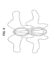
- the spacer comprises two S-shaped members that can pivot about a pair of central elements. Because the S-shaped members are oriented in opposite directions, the spacer has a narrow distal portion in its initial state that allows for its minimally invasive insertion between the adjacent spinous processes. Once this distal portion is positioned substantially on the distal side of the interspinous space, the S-shaped members are rotated past each other in opposite directions about the central element to a final state. As the S-shaped members rotate, the spacer pulls itself into the interspinous space, thereby positioning the central element within the interspinous space. Once in this final position, the two bodies are locked together.
- an interspinous implant for insertion between adjacent spinous processes comprising:
- interspinous refers to the volume located between two adjacent spinous processes of adjacent vertebrae.
- anterior andposterior are used as they are normally used in spinal anatomy. Accordingly, the “anterior” portion of the interspinous device is that portion rests relatively close to the spinal cord, while the “posterior” portion of the interspinous device is that portion rests relatively close to the skin on the patient's back.
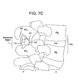
- an anatomic "functional spinal unit” or FSU comprising an upper vertebrae having an upper vertebral body VB U and an upper spinous process SP U , a lower vertebra having a lower vertebral body VB L having a lower spinous process SP L .
- the vertebral bodies lie in the anterior A portion of the FSU, while the spinous processes lie in the posterior portion P of the FSU.
- Disposed between the vertebral bodies is a disc space "disc”.
- Disposed between the spinous process is an "interspinous region”.
- an interspinous implant for insertion between adjacent spinous processes.
- the implant in its initial state comprises:
- the proximal concave arm of the first S-shaped member opposes the proximal concave arm of the second S-shaped member, while similarly the distal concave arm the first S-shaped member opposes the distal concave arm of the second S-shaped member.
- the distal arms of the spacer are inserted between adjacent spinous processes so that these arms will become positioned substantially on the distal (left) side of the interspinous space, while the central element is positioned on the proximal (right) side of the interspinous space.
- an interspinous implant 50 for insertion between adjacent spinous processes The implant is in its initial state and comprises:
- the central element 73 of the second S-shaped member is an independent component, and the distal and proximal arms of the second S-shaped member have throughbores that accommodate the central element.
- an interspinous implant 50 for insertion between adjacent spinous processes The implant is in its final state and comprises:
- FIGS. 6A and 6B The advantage of the design of FIGS. 6A and 6B is that, in its final state, the upper arms lie in the same plane and the lower arms lie in the same plane. That is, the distal concave arm of the first S-shaped member lies in a first plane and the proximal concave arm of the second S-shaped member lies in the first plane. Also, the proximal concave arm of the first S-shaped member lies in a second plane and the distal concave arm of the second S-shaped member lies in the second plane.
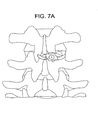
- FIGS. 7A-C there is provided a posterior view of an interspinous implant 101 being inserted between adjacent spinous processes.
- the implant comprises:
- the proximal concave arm of the first S-shaped member opposes the proximal concave arm of the second S-shaped member, while similarly the distal concave arm the first S-shaped member opposes the distal concave arm of the second S-shaped member.
- the distal arms of the spacer are partially inserted between adjacent spinous processes so that these arms are positioned partially on the distal (left) side of the interspinous space, while the central element is positioned on the proximal (right) side of the interspinous space.
- central element 113 contains concave bearing surfaces 153 and 155 for securing the implant to the upper and lower spinous processes.
- the extension of the concave arm in the anterior-posterior direction provides a holding feature 123 that allows for better securement of the device to the spinous process against which it bears.
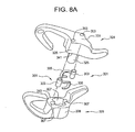
- a first S-shaped member 324 has a projection 325 extending from an inner face 341 of the central element 326 thereof and a second S-shaped member 329 has a corresponding groove 327 extending into the inner face 343 of the central element 328 thereof.
- the projection fits into the groove and may articulate in the groove to allow relative pivoting movement of the arms.
- the implant has a locking element.
- the locking element comprises a pin having a leaf spring.
- the device has a pair of locking elements.
- Each locking element 301 comprises a pin 303 having a leaf spring 305 extending therefrom. This locking element is received in the corresponding cavities 307 in each of the central elements.
- Central element 326 also has cavities 351 corresponding to the pins.
- the pins 303 with leaf springs initially sit completely in cavities 307 in central element 328.
- the cavities of the two central elements become aligned and the pin seated in the cavity 307 pops up to become partially seated in the opposing cavity on central element 326. This locks the implants in its final position.
- the leaf spring pins can be released by inserting a two-pronged key (not shown) in holes 353 on the outside face 331 of the first S-shaped member 324, and holding down the internal leaf spring pins while turning the key.
- the concave arms of the present invention are substantially U-shaped. In some embodiments, the concave arms of the present invention are substantially V-shaped.
- the central portion of the device is angled so that its anterior portion has a thickness that is greater than its posterior portion. This provides a desired angulation to the device.
- each central element has an anterior portion having a thickness and a posterior portion having a thickness, and the thickness of each anterior portion is greater than the thickness of each posterior portion.
- the implant of the present invention is used posteriorly in conjunction with a motion disc inserted within the disc space of the anterior portion of the spinal column.
- the implant of the present invention is used in conjunction with a motion disc having a large range of motion ("ROM").
- ROM large range of motion
- Various motion discs are described by Stefee et al. in U.S. Pat. No. 5,071,437 ; Gill et al. in U.S. Pat. No. 6,113,637 ; Bryan et al. in U.S. Pat. No. 6,001,130 ; Hedman et al. in U.S. Pat. No. 4,759,769 ; Ray in U.S. Pat. No.
- kits for providing therapy to a functional spinal unit comprising an upper vertebrae having an upper spinous process, a lower vertebrae having a lower spinous process, and a disc space therebetween , the kit comprising:
Landscapes
- Health & Medical Sciences (AREA)
- Orthopedic Medicine & Surgery (AREA)
- Life Sciences & Earth Sciences (AREA)
- Neurology (AREA)
- Surgery (AREA)
- Heart & Thoracic Surgery (AREA)
- Engineering & Computer Science (AREA)
- Biomedical Technology (AREA)
- Nuclear Medicine, Radiotherapy & Molecular Imaging (AREA)
- Medical Informatics (AREA)
- Molecular Biology (AREA)
- Animal Behavior & Ethology (AREA)
- General Health & Medical Sciences (AREA)
- Public Health (AREA)
- Veterinary Medicine (AREA)
- Prostheses (AREA)
Claims (13)
- Interspinöses Implantat (101) zur Einführung zwischen benachbarten Dornfortsätzen, wobei das Implantat Folgendes umfasst:a) ein erstes S-förmiges Glied (111; 324) mit einem zentralen Element (113; 326), einem distalen konkaven Arm (117) mit einem am zentralen Element befestigten proximalen Ende (119) und einem proximalen konkaven Arm (123) mit einem am zentralen Element befestigten distalen Ende (125), worin die konkaven Arme voneinander weg weisen, undb) ein zweites S-förmiges Glied (131; 329) mit einem zentralen Element (133; 328), einem distalen konkaven Arm (137) mit einem am zentralen Element befestigten proximalen Ende (139) und einem proximalen konkaven Arm (143) mit einem am zentralen Element befestigten distalen Ende (145), worin die konkaven Arme voneinander weg weisen,
worin die zentralen Elemente der ersten und zweiten Glieder schwenkbar verbunden sind, und gekennzeichnet durch
ein Paar von Arretierungselementen (301), wobei jedes Arretierungselement einen Stift (303) mit einer sich von ihm weg erstreckenden Blattfeder (305) umfasst, worin jedes Arretierungselement in einem entsprechenden Hohlraum (307) in jedem der zentralen Elemente aufgenommen ist. - Implantat nach Anspruch 1, worin der proximale konkave Arm des ersten S-förmigen Glieds in einem Anfangszustand dem proximalen konkaven Arm des zweiten S-förmigen Glieds gegenüberliegt.
- Implantat nach Anspruch 1, worin der distale konkave Arm des ersten S-förmigen Glieds in einem Anfangszustand dem distalen konkaven Arm des zweiten S-förmigen Glieds gegenüberliegt.
- Implantat nach Anspruch 1, worin der distale konkave Arm des ersten S-förmigen Glieds in einem Endzustand dem proximalen konkaven Arm des zweiten S-förmigen Glieds gegenüberliegt.
- Implantat nach Anspruch 1, worin der distale konkave Arm des zweiten S-förmigen Glieds in einem Endzustand dem proximalen konkaven Arm des ersten S-förmigen Glieds gegenüberliegt.
- Implantat nach Anspruch 1, worin zumindest eines der zentralen Elemente eine Oberseite (153) aufweist, die auf einem oberen Dornfortsatz in einem expandierten Zustand anliegen kann.
- Implantat nach Anspruch 1, worin zumindest eines der zentralen Elemente eine Unterseite (155) aufweist, die auf einem unteren Dornfortsatz in einem expandierten Zustand anliegen kann.
- Implantat nach Anspruch 1, worin das Arretierungselement freisetzbar ist.
- Implantat nach Anspruch 1, worin der distale konkave Arm des S-förmigen Glieds in einer ersten Ebene liegt und der distale konkave Arm des zweiten S-förmigen Glieds in einer zweiten unterschiedlichen Ebene liegt.
- Implantat nach Anspruch 1, worin zumindest ein Arm ein Haltemerkmal (123) aufweist.
- Implantat nach Anspruch 1, worin zumindest ein zentrales Element einen vorderen Abschnitt mit einer Dicke und einen hinteren Abschnitt mit einer Dicke aufweist, und worin die Dicke des vorderen Abschnitts größer ist als die Dicke des hinteren Abschnitts.
- Implantat nach Anspruch 1, worin der distale konkave Arm des ersten S-förmigen Glieds in einer ersten Ebene liegt und der proximale konkave Arm des zweiten S-förmigen Glieds in der ersten Ebene liegt.
- Implantat nach Anspruch 1, worin die distalen konkaven Arme beim Schwenken einander passieren können.
Applications Claiming Priority (2)
| Application Number | Priority Date | Filing Date | Title |
|---|---|---|---|
| US11/315,660 US7585313B2 (en) | 2005-12-22 | 2005-12-22 | Rotatable interspinous spacer |
| PCT/US2006/048021 WO2007075470A2 (en) | 2005-12-22 | 2006-12-18 | Rotatable interspinous spacer |
Publications (3)
| Publication Number | Publication Date |
|---|---|
| EP1968495A2 EP1968495A2 (de) | 2008-09-17 |
| EP1968495A4 EP1968495A4 (de) | 2012-03-07 |
| EP1968495B1 true EP1968495B1 (de) | 2013-05-08 |
Family
ID=38218480
Family Applications (1)
| Application Number | Title | Priority Date | Filing Date |
|---|---|---|---|
| EP06847679.5A Active EP1968495B1 (de) | 2005-12-22 | 2006-12-18 | Drehbares interspinöses abstandselement |
Country Status (4)
| Country | Link |
|---|---|
| US (1) | US7585313B2 (de) |
| EP (1) | EP1968495B1 (de) |
| AU (1) | AU2006332002A1 (de) |
| WO (1) | WO2007075470A2 (de) |
Families Citing this family (110)
| Publication number | Priority date | Publication date | Assignee | Title |
|---|---|---|---|---|
| US8409282B2 (en) | 2004-10-20 | 2013-04-02 | Vertiflex, Inc. | Systems and methods for posterior dynamic stabilization of the spine |
| US8277488B2 (en) | 2004-10-20 | 2012-10-02 | Vertiflex, Inc. | Interspinous spacer |
| US8945183B2 (en) | 2004-10-20 | 2015-02-03 | Vertiflex, Inc. | Interspinous process spacer instrument system with deployment indicator |
| US8425559B2 (en) | 2004-10-20 | 2013-04-23 | Vertiflex, Inc. | Systems and methods for posterior dynamic stabilization of the spine |
| US8167944B2 (en) | 2004-10-20 | 2012-05-01 | The Board Of Trustees Of The Leland Stanford Junior University | Systems and methods for posterior dynamic stabilization of the spine |
| US9161783B2 (en) | 2004-10-20 | 2015-10-20 | Vertiflex, Inc. | Interspinous spacer |
| US8123782B2 (en) | 2004-10-20 | 2012-02-28 | Vertiflex, Inc. | Interspinous spacer |
| US8273108B2 (en) | 2004-10-20 | 2012-09-25 | Vertiflex, Inc. | Interspinous spacer |
| US7763074B2 (en) | 2004-10-20 | 2010-07-27 | The Board Of Trustees Of The Leland Stanford Junior University | Systems and methods for posterior dynamic stabilization of the spine |
| US8317864B2 (en) | 2004-10-20 | 2012-11-27 | The Board Of Trustees Of The Leland Stanford Junior University | Systems and methods for posterior dynamic stabilization of the spine |
| US8123807B2 (en) | 2004-10-20 | 2012-02-28 | Vertiflex, Inc. | Systems and methods for posterior dynamic stabilization of the spine |
| US9119680B2 (en) | 2004-10-20 | 2015-09-01 | Vertiflex, Inc. | Interspinous spacer |
| US8613747B2 (en) | 2004-10-20 | 2013-12-24 | Vertiflex, Inc. | Spacer insertion instrument |
| US8128662B2 (en) | 2004-10-20 | 2012-03-06 | Vertiflex, Inc. | Minimally invasive tooling for delivery of interspinous spacer |
| US9023084B2 (en) | 2004-10-20 | 2015-05-05 | The Board Of Trustees Of The Leland Stanford Junior University | Systems and methods for stabilizing the motion or adjusting the position of the spine |
| US8152837B2 (en) | 2004-10-20 | 2012-04-10 | The Board Of Trustees Of The Leland Stanford Junior University | Systems and methods for posterior dynamic stabilization of the spine |
| US8012207B2 (en) | 2004-10-20 | 2011-09-06 | Vertiflex, Inc. | Systems and methods for posterior dynamic stabilization of the spine |
| US9055981B2 (en) | 2004-10-25 | 2015-06-16 | Lanx, Inc. | Spinal implants and methods |
| US8241330B2 (en) | 2007-01-11 | 2012-08-14 | Lanx, Inc. | Spinous process implants and associated methods |
| US8172855B2 (en) | 2004-11-24 | 2012-05-08 | Abdou M S | Devices and methods for inter-vertebral orthopedic device placement |
| EP2219538B1 (de) | 2004-12-06 | 2022-07-06 | Vertiflex, Inc. | Instrument zum einsetzen von abstandsstücken |
| US9675385B2 (en) | 2005-04-12 | 2017-06-13 | Nathan C. Moskowitz | Spinous process staple with interdigitating-interlocking hemi-spacers for adjacent spinous process separation and distraction |
| FR2888744B1 (fr) * | 2005-07-21 | 2007-08-24 | Charles Khalife | Dispositif inter epineux rotatoire |
| US8430911B2 (en) * | 2005-12-14 | 2013-04-30 | Spinefrontier Inc | Spinous process fixation implant |
| US7828847B2 (en) * | 2006-02-15 | 2010-11-09 | Samy Abdou | Devices and methods for inter-vertebral orthopedic device placement |
| US8361116B2 (en) | 2006-03-24 | 2013-01-29 | U.S. Spine, Inc. | Non-pedicle based interspinous spacer |
| GB0605960D0 (en) * | 2006-03-24 | 2006-05-03 | Galley Geoffrey H | Expandable spinal prosthesis |
| US7985246B2 (en) * | 2006-03-31 | 2011-07-26 | Warsaw Orthopedic, Inc. | Methods and instruments for delivering interspinous process spacers |
| US8303660B1 (en) | 2006-04-22 | 2012-11-06 | Samy Abdou | Inter-vertebral disc prosthesis with variable rotational stop and methods of use |
| WO2007134113A2 (en) * | 2006-05-09 | 2007-11-22 | Raymedica, Llc | Systems and methods for stabilizing a functional spinal unit |
| EP2032086A4 (de) * | 2006-05-26 | 2013-01-16 | Samy M Abdou | Bandscheibenbewegungsvorrichtungen und anwendungsverfahren |
| US20080039843A1 (en) | 2006-08-11 | 2008-02-14 | Abdou M S | Spinal motion preservation devices and methods of use |
| US8845726B2 (en) | 2006-10-18 | 2014-09-30 | Vertiflex, Inc. | Dilator |
| US8105382B2 (en) | 2006-12-07 | 2012-01-31 | Interventional Spine, Inc. | Intervertebral implant |
| EP2101691A4 (de) | 2006-12-11 | 2013-08-07 | Samy M Abdou | Dynamische wirbelsäulen-stabilisierungssysteme und anwendungsverfahren |
| US9265532B2 (en) | 2007-01-11 | 2016-02-23 | Lanx, Inc. | Interspinous implants and methods |
| ES2968634T3 (es) * | 2007-02-06 | 2024-05-13 | Pioneer Surgical Tech Inc | Dispositivos de implante intervertebral |
| WO2008124802A2 (en) * | 2007-04-10 | 2008-10-16 | Medicinelodge, Inc. | Interspinous process spacers |
| EP2155121B1 (de) | 2007-04-16 | 2015-06-17 | Vertiflex, Inc. | Interspinöses abstandsglied |
| US9381047B2 (en) | 2007-05-09 | 2016-07-05 | Ebi, Llc | Interspinous implant |
| US9173686B2 (en) * | 2007-05-09 | 2015-11-03 | Ebi, Llc | Interspinous implant |
| US8070779B2 (en) * | 2007-06-04 | 2011-12-06 | K2M, Inc. | Percutaneous interspinous process device and method |
| US8900307B2 (en) | 2007-06-26 | 2014-12-02 | DePuy Synthes Products, LLC | Highly lordosed fusion cage |
| DE102007052799A1 (de) * | 2007-11-02 | 2009-05-07 | Taurus Gmbh & Co.Kg. | Implantat |
| US9232968B2 (en) | 2007-12-19 | 2016-01-12 | DePuy Synthes Products, Inc. | Polymeric pedicle rods and methods of manufacturing |
| CA2711955C (en) | 2008-01-15 | 2016-05-17 | Vertiflex, Inc. | Interspinous spacer |
| AU2009205896A1 (en) | 2008-01-17 | 2009-07-23 | Synthes Gmbh | An expandable intervertebral implant and associated method of manufacturing the same |
| US8313512B2 (en) * | 2008-03-26 | 2012-11-20 | Depuy Spine, Inc. | S-shaped interspinous process spacer having tight access offset hooks |
| BRPI0910325A8 (pt) | 2008-04-05 | 2019-01-29 | Synthes Gmbh | implante intervertebral expansível |
| DE102008032685B4 (de) * | 2008-07-04 | 2016-06-23 | Aesculap Ag | Implantat zur gegenseitigen Abstützung der Dornfortsätze von Wirbelkörpern |
| EP2430995B1 (de) * | 2008-08-08 | 2016-03-30 | Alphatec Spine, Inc. | Wirbelfortsatzvorrichtung |
| TW201023814A (en) * | 2008-12-30 | 2010-07-01 | Ind Tech Res Inst | Spinal dynamic stabilization device |
| US8641734B2 (en) | 2009-02-13 | 2014-02-04 | DePuy Synthes Products, LLC | Dual spring posterior dynamic stabilization device with elongation limiting elastomers |
| US8945184B2 (en) * | 2009-03-13 | 2015-02-03 | Spinal Simplicity Llc. | Interspinous process implant and fusion cage spacer |
| US9526620B2 (en) | 2009-03-30 | 2016-12-27 | DePuy Synthes Products, Inc. | Zero profile spinal fusion cage |
| EP2413825A4 (de) | 2009-03-31 | 2013-12-11 | Lanx Inc | Dornfortsatzimplantate und zugehörige verfahren |
| US20120150309A1 (en) * | 2009-04-29 | 2012-06-14 | Roelof Marissen | Hinge structure |
| US9320543B2 (en) | 2009-06-25 | 2016-04-26 | DePuy Synthes Products, Inc. | Posterior dynamic stabilization device having a mobile anchor |
| US8764806B2 (en) | 2009-12-07 | 2014-07-01 | Samy Abdou | Devices and methods for minimally invasive spinal stabilization and instrumentation |
| US9393129B2 (en) | 2009-12-10 | 2016-07-19 | DePuy Synthes Products, Inc. | Bellows-like expandable interbody fusion cage |
| EP2512357B1 (de) | 2009-12-15 | 2016-07-13 | Vertiflex, Inc. | Wirbelsäulenabstandsstück für gebärmutter- und andere wirbel sowie entsprechende systeme |
| US8262697B2 (en) | 2010-01-14 | 2012-09-11 | X-Spine Systems, Inc. | Modular interspinous fixation system and method |
| DE102010000231A1 (de) | 2010-01-27 | 2011-07-28 | Aesculap AG, 78532 | Implantat zur gegenseitigen Abstützung der Dornfortsätze benachbarter Wirbelkörper sowie chirurgisches System |
| DE102010000230A1 (de) | 2010-01-27 | 2011-07-28 | Aesculap AG, 78532 | Chirurgisches Instrumentarium |
| US8388656B2 (en) * | 2010-02-04 | 2013-03-05 | Ebi, Llc | Interspinous spacer with deployable members and related method |
| US9445844B2 (en) * | 2010-03-24 | 2016-09-20 | DePuy Synthes Products, Inc. | Composite material posterior dynamic stabilization spring rod |
| US9072549B2 (en) * | 2010-06-16 | 2015-07-07 | Life Spine, Inc. | Spinal clips for interspinous decompression |
| US9763678B2 (en) | 2010-06-24 | 2017-09-19 | DePuy Synthes Products, Inc. | Multi-segment lateral cage adapted to flex substantially in the coronal plane |
| US8979860B2 (en) | 2010-06-24 | 2015-03-17 | DePuy Synthes Products. LLC | Enhanced cage insertion device |
| AU2011271465B2 (en) | 2010-06-29 | 2015-03-19 | Synthes Gmbh | Distractible intervertebral implant |
| US9402732B2 (en) | 2010-10-11 | 2016-08-02 | DePuy Synthes Products, Inc. | Expandable interspinous process spacer implant |
| US8512408B2 (en) | 2010-12-17 | 2013-08-20 | Warsaw Orthopedic, Inc. | Flexiable spinal implant |
| US8496689B2 (en) | 2011-02-23 | 2013-07-30 | Farzad Massoudi | Spinal implant device with fusion cage and fixation plates and method of implanting |
| US8425560B2 (en) | 2011-03-09 | 2013-04-23 | Farzad Massoudi | Spinal implant device with fixation plates and lag screws and method of implanting |
| US20120323276A1 (en) * | 2011-06-17 | 2012-12-20 | Bryan Okamoto | Expandable interspinous device |
| US9149306B2 (en) | 2011-06-21 | 2015-10-06 | Seaspine, Inc. | Spinous process device |
| US8845728B1 (en) | 2011-09-23 | 2014-09-30 | Samy Abdou | Spinal fixation devices and methods of use |
| US11812923B2 (en) | 2011-10-07 | 2023-11-14 | Alan Villavicencio | Spinal fixation device |
| US9119683B2 (en) | 2012-01-18 | 2015-09-01 | Warsaw Orthopedic, Inc. | Interspinous implant with overlapping arms |
| US10188434B2 (en) * | 2012-02-17 | 2019-01-29 | The University Of Toledo | Hybrid multifunctional posterior interspinous fusion device |
| US20130226240A1 (en) | 2012-02-22 | 2013-08-29 | Samy Abdou | Spinous process fixation devices and methods of use |
| EP2846717B1 (de) | 2012-05-11 | 2016-08-24 | Aesculap AG | Implantat zur stabilisierung von dornfortsätzen |
| US9198767B2 (en) | 2012-08-28 | 2015-12-01 | Samy Abdou | Devices and methods for spinal stabilization and instrumentation |
| US9320617B2 (en) | 2012-10-22 | 2016-04-26 | Cogent Spine, LLC | Devices and methods for spinal stabilization and instrumentation |
| US9717601B2 (en) | 2013-02-28 | 2017-08-01 | DePuy Synthes Products, Inc. | Expandable intervertebral implant, system, kit and method |
| US9522070B2 (en) | 2013-03-07 | 2016-12-20 | Interventional Spine, Inc. | Intervertebral implant |
| US9675303B2 (en) | 2013-03-15 | 2017-06-13 | Vertiflex, Inc. | Visualization systems, instruments and methods of using the same in spinal decompression procedures |
| MX374986B (es) * | 2013-06-14 | 2025-03-06 | Spinal Simplicity Llc | Implante de proceso interespinoso que tiene brazos de acoplamiento accionados por pasador. |
| EP3139848A4 (de) | 2014-05-07 | 2018-06-13 | Vertiflex, Inc. | Spinalnervdekomprimierungssysteme, dilatationssysteme und verfahren zur verwendung davon |
| US9987052B2 (en) | 2015-02-24 | 2018-06-05 | X-Spine Systems, Inc. | Modular interspinous fixation system with threaded component |
| US11426290B2 (en) | 2015-03-06 | 2022-08-30 | DePuy Synthes Products, Inc. | Expandable intervertebral implant, system, kit and method |
| US10857003B1 (en) | 2015-10-14 | 2020-12-08 | Samy Abdou | Devices and methods for vertebral stabilization |
| CN109640889B (zh) | 2016-06-28 | 2021-07-30 | Eit 新兴移植技术股份有限公司 | 可扩张的角度可调节式关节运动椎间保持架 |
| JP6995789B2 (ja) | 2016-06-28 | 2022-01-17 | イーアイティー・エマージング・インプラント・テクノロジーズ・ゲーエムベーハー | 拡張可能かつ角度調節可能な椎間ケージ |
| US10973648B1 (en) | 2016-10-25 | 2021-04-13 | Samy Abdou | Devices and methods for vertebral bone realignment |
| US10744000B1 (en) | 2016-10-25 | 2020-08-18 | Samy Abdou | Devices and methods for vertebral bone realignment |
| US10398563B2 (en) | 2017-05-08 | 2019-09-03 | Medos International Sarl | Expandable cage |
| US11344424B2 (en) | 2017-06-14 | 2022-05-31 | Medos International Sarl | Expandable intervertebral implant and related methods |
| EP3678602A4 (de) | 2017-09-08 | 2021-10-06 | Pioneer Surgical Technology, Inc. | Bandscheibenimplantate, instrumente und verfahren |
| USD907771S1 (en) | 2017-10-09 | 2021-01-12 | Pioneer Surgical Technology, Inc. | Intervertebral implant |
| US11179248B2 (en) | 2018-10-02 | 2021-11-23 | Samy Abdou | Devices and methods for spinal implantation |
| US11446156B2 (en) | 2018-10-25 | 2022-09-20 | Medos International Sarl | Expandable intervertebral implant, inserter instrument, and related methods |
| US11426286B2 (en) | 2020-03-06 | 2022-08-30 | Eit Emerging Implant Technologies Gmbh | Expandable intervertebral implant |
| US11850160B2 (en) | 2021-03-26 | 2023-12-26 | Medos International Sarl | Expandable lordotic intervertebral fusion cage |
| US11752009B2 (en) | 2021-04-06 | 2023-09-12 | Medos International Sarl | Expandable intervertebral fusion cage |
| EP4426216B1 (de) | 2022-02-15 | 2025-06-04 | Boston Scientific Neuromodulation Corporation | Interspinöse abstandsvorrichtung und systeme mit der interspinösen abstandsvorrichtung |
| US12090064B2 (en) | 2022-03-01 | 2024-09-17 | Medos International Sarl | Stabilization members for expandable intervertebral implants, and related systems and methods |
| US12133664B2 (en) | 2022-12-13 | 2024-11-05 | Spinal Simplicity, Llc | Medical implant |
| US12433646B2 (en) | 2023-02-21 | 2025-10-07 | Boston Scientific Neuromodulation Corporation | Interspinous spacer with actuator locking arrangements and methods and systems |
| US12390340B2 (en) | 2023-03-15 | 2025-08-19 | Boston Scientific Neuromodulation Corporation | Interspinous spacer with a range of deployment positions and methods and systems |
Family Cites Families (21)
| Publication number | Priority date | Publication date | Assignee | Title |
|---|---|---|---|---|
| CA1283501C (en) * | 1987-02-12 | 1991-04-30 | Thomas P. Hedman | Artificial spinal disc |
| CA1318469C (en) * | 1989-02-15 | 1993-06-01 | Acromed Corporation | Artificial disc |
| DE4208116C2 (de) * | 1992-03-13 | 1995-08-03 | Link Waldemar Gmbh Co | Bandscheibenendoprothese |
| FR2722980B1 (fr) * | 1994-07-26 | 1996-09-27 | Samani Jacques | Implant vertebral inter-epineux |
| US5527312A (en) * | 1994-08-19 | 1996-06-18 | Salut, Ltd. | Facet screw anchor |
| US5824093A (en) * | 1994-10-17 | 1998-10-20 | Raymedica, Inc. | Prosthetic spinal disc nucleus |
| US5674296A (en) * | 1994-11-14 | 1997-10-07 | Spinal Dynamics Corporation | Human spinal disc prosthesis |
| US6068630A (en) * | 1997-01-02 | 2000-05-30 | St. Francis Medical Technologies, Inc. | Spine distraction implant |
| US7959652B2 (en) * | 2005-04-18 | 2011-06-14 | Kyphon Sarl | Interspinous process implant having deployable wings and method of implantation |
| FR2767675B1 (fr) * | 1997-08-26 | 1999-12-03 | Materiel Orthopedique En Abreg | Implant intersomatique et ancillaire de preparation adapte pour permettre sa pose |
| US5824094A (en) * | 1997-10-17 | 1998-10-20 | Acromed Corporation | Spinal disc |
| US6113637A (en) * | 1998-10-22 | 2000-09-05 | Sofamor Danek Holdings, Inc. | Artificial intervertebral joint permitting translational and rotational motion |
| EP2204144B1 (de) * | 1999-10-22 | 2013-04-03 | Gmedelaware 2 LLC | Facettenarthroplastiegeräte und Verfahren |
| TW411838U (en) * | 1999-12-10 | 2000-11-11 | Ye Jung Chiuan | Fastening hook for spine and reposition device for fastening spine |
| BR0209501B1 (pt) | 2001-05-11 | 2011-02-08 | aparelho e método para a formação de corrugações em tubos. | |
| WO2003015645A1 (de) * | 2001-08-20 | 2003-02-27 | Synthes Ag Chur | Interspinale prothese |
| US7585316B2 (en) * | 2004-05-21 | 2009-09-08 | Warsaw Orthopedic, Inc. | Interspinous spacer |
| ITPD20050231A1 (it) * | 2005-07-28 | 2007-01-29 | 2B1 Srl | Apparato per il trattamento neurochirurgico-ortopedico di patologie della colonna vertebrale umana |
| US7753938B2 (en) * | 2005-08-05 | 2010-07-13 | Synthes Usa, Llc | Apparatus for treating spinal stenosis |
| US7985246B2 (en) * | 2006-03-31 | 2011-07-26 | Warsaw Orthopedic, Inc. | Methods and instruments for delivering interspinous process spacers |
| WO2008013960A2 (en) * | 2006-07-27 | 2008-01-31 | Abdou Samy M | Devices and methods for the minimally invasive treatment of spinal stenosis |
-
2005
- 2005-12-22 US US11/315,660 patent/US7585313B2/en active Active
-
2006
- 2006-12-18 AU AU2006332002A patent/AU2006332002A1/en not_active Abandoned
- 2006-12-18 EP EP06847679.5A patent/EP1968495B1/de active Active
- 2006-12-18 WO PCT/US2006/048021 patent/WO2007075470A2/en not_active Ceased
Also Published As
| Publication number | Publication date |
|---|---|
| US7585313B2 (en) | 2009-09-08 |
| US20070161992A1 (en) | 2007-07-12 |
| AU2006332002A1 (en) | 2007-07-05 |
| WO2007075470A2 (en) | 2007-07-05 |
| EP1968495A2 (de) | 2008-09-17 |
| WO2007075470A3 (en) | 2009-01-22 |
| EP1968495A4 (de) | 2012-03-07 |
Similar Documents
| Publication | Publication Date | Title |
|---|---|---|
| US7585313B2 (en) | Rotatable interspinous spacer | |
| EP1725191B1 (de) | Abstandshalter für die Dornfortsätze | |
| US10512489B2 (en) | Dynamized interspinal implant | |
| US8252026B2 (en) | Spinal implant for facet joint | |
| US8652174B2 (en) | Expandable interspinous process spacer | |
| US9320549B2 (en) | Spinal fixation plates | |
| US7887589B2 (en) | Minimally invasive spinal disc stabilizer and insertion tool | |
| US20160331411A1 (en) | Dynamic Fixation Device and Method of Use | |
| EP2446843B1 (de) | Interspinöse Abstandsglied-anordnung | |
| US8267970B2 (en) | Laminar hook spring |
Legal Events
| Date | Code | Title | Description |
|---|---|---|---|
| PUAI | Public reference made under article 153(3) epc to a published international application that has entered the european phase |
Free format text: ORIGINAL CODE: 0009012 |
|
| 17P | Request for examination filed |
Effective date: 20080722 |
|
| AK | Designated contracting states |
Kind code of ref document: A2 Designated state(s): AT BE BG CH CY CZ DE DK EE ES FI FR GB GR HU IE IS IT LI LT LU LV MC NL PL PT RO SE SI SK TR |
|
| AX | Request for extension of the european patent |
Extension state: AL BA HR MK RS |
|
| R17D | Deferred search report published (corrected) |
Effective date: 20090122 |
|
| RIC1 | Information provided on ipc code assigned before grant |
Ipc: A61B 17/70 20060101AFI20090312BHEP |
|
| REG | Reference to a national code |
Ref country code: DE Ref legal event code: R079 Ref document number: 602006036229 Country of ref document: DE Free format text: PREVIOUS MAIN CLASS: A61F0002300000 Ipc: A61B0017700000 |
|
| A4 | Supplementary search report drawn up and despatched |
Effective date: 20120203 |
|
| RIC1 | Information provided on ipc code assigned before grant |
Ipc: A61B 17/70 20060101AFI20120130BHEP |
|
| DAX | Request for extension of the european patent (deleted) | ||
| GRAP | Despatch of communication of intention to grant a patent |
Free format text: ORIGINAL CODE: EPIDOSNIGR1 |
|
| GRAS | Grant fee paid |
Free format text: ORIGINAL CODE: EPIDOSNIGR3 |
|
| GRAA | (expected) grant |
Free format text: ORIGINAL CODE: 0009210 |
|
| AK | Designated contracting states |
Kind code of ref document: B1 Designated state(s): AT BE BG CH CY CZ DE DK EE ES FI FR GB GR HU IE IS IT LI LT LU LV MC NL PL PT RO SE SI SK TR |
|
| REG | Reference to a national code |
Ref country code: GB Ref legal event code: FG4D |
|
| REG | Reference to a national code |
Ref country code: CH Ref legal event code: NV Representative=s name: E. BLUM AND CO. AG PATENT- UND MARKENANWAELTE , CH Ref country code: CH Ref legal event code: EP Ref country code: AT Ref legal event code: REF Ref document number: 610675 Country of ref document: AT Kind code of ref document: T Effective date: 20130515 |
|
| REG | Reference to a national code |
Ref country code: IE Ref legal event code: FG4D |
|
| REG | Reference to a national code |
Ref country code: DE Ref legal event code: R096 Ref document number: 602006036229 Country of ref document: DE Effective date: 20130704 |
|
| REG | Reference to a national code |
Ref country code: AT Ref legal event code: MK05 Ref document number: 610675 Country of ref document: AT Kind code of ref document: T Effective date: 20130508 |
|
| REG | Reference to a national code |
Ref country code: LT Ref legal event code: MG4D |
|
| REG | Reference to a national code |
Ref country code: NL Ref legal event code: VDEP Effective date: 20130508 |
|
| PG25 | Lapsed in a contracting state [announced via postgrant information from national office to epo] |
Ref country code: LT Free format text: LAPSE BECAUSE OF FAILURE TO SUBMIT A TRANSLATION OF THE DESCRIPTION OR TO PAY THE FEE WITHIN THE PRESCRIBED TIME-LIMIT Effective date: 20130508 Ref country code: SI Free format text: LAPSE BECAUSE OF FAILURE TO SUBMIT A TRANSLATION OF THE DESCRIPTION OR TO PAY THE FEE WITHIN THE PRESCRIBED TIME-LIMIT Effective date: 20130508 Ref country code: GR Free format text: LAPSE BECAUSE OF FAILURE TO SUBMIT A TRANSLATION OF THE DESCRIPTION OR TO PAY THE FEE WITHIN THE PRESCRIBED TIME-LIMIT Effective date: 20130809 Ref country code: AT Free format text: LAPSE BECAUSE OF FAILURE TO SUBMIT A TRANSLATION OF THE DESCRIPTION OR TO PAY THE FEE WITHIN THE PRESCRIBED TIME-LIMIT Effective date: 20130508 Ref country code: FI Free format text: LAPSE BECAUSE OF FAILURE TO SUBMIT A TRANSLATION OF THE DESCRIPTION OR TO PAY THE FEE WITHIN THE PRESCRIBED TIME-LIMIT Effective date: 20130508 Ref country code: IS Free format text: LAPSE BECAUSE OF FAILURE TO SUBMIT A TRANSLATION OF THE DESCRIPTION OR TO PAY THE FEE WITHIN THE PRESCRIBED TIME-LIMIT Effective date: 20130908 Ref country code: SE Free format text: LAPSE BECAUSE OF FAILURE TO SUBMIT A TRANSLATION OF THE DESCRIPTION OR TO PAY THE FEE WITHIN THE PRESCRIBED TIME-LIMIT Effective date: 20130508 Ref country code: PT Free format text: LAPSE BECAUSE OF FAILURE TO SUBMIT A TRANSLATION OF THE DESCRIPTION OR TO PAY THE FEE WITHIN THE PRESCRIBED TIME-LIMIT Effective date: 20130909 Ref country code: ES Free format text: LAPSE BECAUSE OF FAILURE TO SUBMIT A TRANSLATION OF THE DESCRIPTION OR TO PAY THE FEE WITHIN THE PRESCRIBED TIME-LIMIT Effective date: 20130819 |
|
| PG25 | Lapsed in a contracting state [announced via postgrant information from national office to epo] |
Ref country code: CY Free format text: LAPSE BECAUSE OF FAILURE TO SUBMIT A TRANSLATION OF THE DESCRIPTION OR TO PAY THE FEE WITHIN THE PRESCRIBED TIME-LIMIT Effective date: 20130508 Ref country code: PL Free format text: LAPSE BECAUSE OF FAILURE TO SUBMIT A TRANSLATION OF THE DESCRIPTION OR TO PAY THE FEE WITHIN THE PRESCRIBED TIME-LIMIT Effective date: 20130508 Ref country code: BG Free format text: LAPSE BECAUSE OF FAILURE TO SUBMIT A TRANSLATION OF THE DESCRIPTION OR TO PAY THE FEE WITHIN THE PRESCRIBED TIME-LIMIT Effective date: 20130808 |
|
| PG25 | Lapsed in a contracting state [announced via postgrant information from national office to epo] |
Ref country code: LV Free format text: LAPSE BECAUSE OF FAILURE TO SUBMIT A TRANSLATION OF THE DESCRIPTION OR TO PAY THE FEE WITHIN THE PRESCRIBED TIME-LIMIT Effective date: 20130508 |
|
| PG25 | Lapsed in a contracting state [announced via postgrant information from national office to epo] |
Ref country code: CZ Free format text: LAPSE BECAUSE OF FAILURE TO SUBMIT A TRANSLATION OF THE DESCRIPTION OR TO PAY THE FEE WITHIN THE PRESCRIBED TIME-LIMIT Effective date: 20130508 Ref country code: BE Free format text: LAPSE BECAUSE OF FAILURE TO SUBMIT A TRANSLATION OF THE DESCRIPTION OR TO PAY THE FEE WITHIN THE PRESCRIBED TIME-LIMIT Effective date: 20130508 Ref country code: SK Free format text: LAPSE BECAUSE OF FAILURE TO SUBMIT A TRANSLATION OF THE DESCRIPTION OR TO PAY THE FEE WITHIN THE PRESCRIBED TIME-LIMIT Effective date: 20130508 Ref country code: DK Free format text: LAPSE BECAUSE OF FAILURE TO SUBMIT A TRANSLATION OF THE DESCRIPTION OR TO PAY THE FEE WITHIN THE PRESCRIBED TIME-LIMIT Effective date: 20130508 Ref country code: EE Free format text: LAPSE BECAUSE OF FAILURE TO SUBMIT A TRANSLATION OF THE DESCRIPTION OR TO PAY THE FEE WITHIN THE PRESCRIBED TIME-LIMIT Effective date: 20130508 |
|
| PG25 | Lapsed in a contracting state [announced via postgrant information from national office to epo] |
Ref country code: NL Free format text: LAPSE BECAUSE OF FAILURE TO SUBMIT A TRANSLATION OF THE DESCRIPTION OR TO PAY THE FEE WITHIN THE PRESCRIBED TIME-LIMIT Effective date: 20130508 Ref country code: RO Free format text: LAPSE BECAUSE OF FAILURE TO SUBMIT A TRANSLATION OF THE DESCRIPTION OR TO PAY THE FEE WITHIN THE PRESCRIBED TIME-LIMIT Effective date: 20130508 |
|
| PLBE | No opposition filed within time limit |
Free format text: ORIGINAL CODE: 0009261 |
|
| STAA | Information on the status of an ep patent application or granted ep patent |
Free format text: STATUS: NO OPPOSITION FILED WITHIN TIME LIMIT |
|
| 26N | No opposition filed |
Effective date: 20140211 |
|
| REG | Reference to a national code |
Ref country code: DE Ref legal event code: R097 Ref document number: 602006036229 Country of ref document: DE Effective date: 20140211 |
|
| PG25 | Lapsed in a contracting state [announced via postgrant information from national office to epo] |
Ref country code: LU Free format text: LAPSE BECAUSE OF FAILURE TO SUBMIT A TRANSLATION OF THE DESCRIPTION OR TO PAY THE FEE WITHIN THE PRESCRIBED TIME-LIMIT Effective date: 20131218 Ref country code: MC Free format text: LAPSE BECAUSE OF FAILURE TO SUBMIT A TRANSLATION OF THE DESCRIPTION OR TO PAY THE FEE WITHIN THE PRESCRIBED TIME-LIMIT Effective date: 20130508 |
|
| REG | Reference to a national code |
Ref country code: IE Ref legal event code: MM4A |
|
| PG25 | Lapsed in a contracting state [announced via postgrant information from national office to epo] |
Ref country code: IE Free format text: LAPSE BECAUSE OF NON-PAYMENT OF DUE FEES Effective date: 20131218 |
|
| PG25 | Lapsed in a contracting state [announced via postgrant information from national office to epo] |
Ref country code: TR Free format text: LAPSE BECAUSE OF FAILURE TO SUBMIT A TRANSLATION OF THE DESCRIPTION OR TO PAY THE FEE WITHIN THE PRESCRIBED TIME-LIMIT Effective date: 20130508 |
|
| PG25 | Lapsed in a contracting state [announced via postgrant information from national office to epo] |
Ref country code: HU Free format text: LAPSE BECAUSE OF FAILURE TO SUBMIT A TRANSLATION OF THE DESCRIPTION OR TO PAY THE FEE WITHIN THE PRESCRIBED TIME-LIMIT; INVALID AB INITIO Effective date: 20061218 |
|
| REG | Reference to a national code |
Ref country code: FR Ref legal event code: PLFP Year of fee payment: 11 |
|
| REG | Reference to a national code |
Ref country code: FR Ref legal event code: PLFP Year of fee payment: 12 |
|
| PGFP | Annual fee paid to national office [announced via postgrant information from national office to epo] |
Ref country code: IT Payment date: 20221111 Year of fee payment: 17 Ref country code: FR Payment date: 20221110 Year of fee payment: 17 Ref country code: DE Payment date: 20220622 Year of fee payment: 17 |
|
| PGFP | Annual fee paid to national office [announced via postgrant information from national office to epo] |
Ref country code: CH Payment date: 20240102 Year of fee payment: 18 |
|
| REG | Reference to a national code |
Ref country code: DE Ref legal event code: R119 Ref document number: 602006036229 Country of ref document: DE |
|
| PG25 | Lapsed in a contracting state [announced via postgrant information from national office to epo] |
Ref country code: DE Free format text: LAPSE BECAUSE OF NON-PAYMENT OF DUE FEES Effective date: 20240702 |
|
| PG25 | Lapsed in a contracting state [announced via postgrant information from national office to epo] |
Ref country code: FR Free format text: LAPSE BECAUSE OF NON-PAYMENT OF DUE FEES Effective date: 20231231 |
|
| PG25 | Lapsed in a contracting state [announced via postgrant information from national office to epo] |
Ref country code: FR Free format text: LAPSE BECAUSE OF NON-PAYMENT OF DUE FEES Effective date: 20231231 Ref country code: DE Free format text: LAPSE BECAUSE OF NON-PAYMENT OF DUE FEES Effective date: 20240702 |
|
| PGFP | Annual fee paid to national office [announced via postgrant information from national office to epo] |
Ref country code: GB Payment date: 20241031 Year of fee payment: 19 |
|
| REG | Reference to a national code |
Ref country code: CH Ref legal event code: PL |
|
| PG25 | Lapsed in a contracting state [announced via postgrant information from national office to epo] |
Ref country code: IT Free format text: LAPSE BECAUSE OF NON-PAYMENT OF DUE FEES Effective date: 20231218 |
|
| PG25 | Lapsed in a contracting state [announced via postgrant information from national office to epo] |
Ref country code: CH Free format text: LAPSE BECAUSE OF NON-PAYMENT OF DUE FEES Effective date: 20241231 |