EP1968212B1 - Multiplexierung der Frequenzen einer Aufwärtsverbindung - Google Patents
Multiplexierung der Frequenzen einer Aufwärtsverbindung Download PDFInfo
- Publication number
- EP1968212B1 EP1968212B1 EP08300124A EP08300124A EP1968212B1 EP 1968212 B1 EP1968212 B1 EP 1968212B1 EP 08300124 A EP08300124 A EP 08300124A EP 08300124 A EP08300124 A EP 08300124A EP 1968212 B1 EP1968212 B1 EP 1968212B1
- Authority
- EP
- European Patent Office
- Prior art keywords
- uplink
- service area
- filters
- multiplexer
- satellite
- Prior art date
- Legal status (The legal status is an assumption and is not a legal conclusion. Google has not performed a legal analysis and makes no representation as to the accuracy of the status listed.)
- Not-in-force
Links
- 230000003321 amplification Effects 0.000 claims abstract description 10
- 238000003199 nucleic acid amplification method Methods 0.000 claims abstract description 10
- 238000001228 spectrum Methods 0.000 claims description 24
- 238000004891 communication Methods 0.000 claims description 9
- 238000010586 diagram Methods 0.000 description 12
- 230000015556 catabolic process Effects 0.000 description 4
- 238000006731 degradation reaction Methods 0.000 description 4
- 230000006978 adaptation Effects 0.000 description 1
- 238000003491 array Methods 0.000 description 1
- 239000002131 composite material Substances 0.000 description 1
- 230000007423 decrease Effects 0.000 description 1
- 238000005516 engineering process Methods 0.000 description 1
- 238000001914 filtration Methods 0.000 description 1
- 230000002452 interceptive effect Effects 0.000 description 1
- 230000007246 mechanism Effects 0.000 description 1
- 238000000034 method Methods 0.000 description 1
- 238000005204 segregation Methods 0.000 description 1
Images

Classifications
-
- H—ELECTRICITY
- H04—ELECTRIC COMMUNICATION TECHNIQUE
- H04B—TRANSMISSION
- H04B7/00—Radio transmission systems, i.e. using radiation field
- H04B7/14—Relay systems
- H04B7/15—Active relay systems
- H04B7/185—Space-based or airborne stations; Stations for satellite systems
- H04B7/1851—Systems using a satellite or space-based relay
- H04B7/18515—Transmission equipment in satellites or space-based relays
Definitions
- the invention relates to a satellite transponder for two or more uplink service areas and a satellite communication system comprising such a transponder.
- the present invention relates to a satellite-borne transponder for two or more uplink service areas and a satellite communication system comprising such a satellite-borne transponder, even if sometimes it is written "satellite transponder” or "transponder” only.
- each transponder is associated with a single uplink service area and a single downlink service area.
- the disadvantage of such a scheme is that if traffic exists from two or more service areas to a given service area, several transponders are required for connectivity purposes, even if the total required capacity is compatible with that of a single transponder. This does not represent efficient or optimal use of the satellite resources, in terms of Radio Frequency resources (bandwidth) and power resources.
- a conventional architecture associating a transponder with multiple service areas degrades the figure of merit (also called G/T) which, in the present case, is the relationship between the gain G of the antenna and the noise temperature T over the uplink service areas.
- G/T figure of merit
- the object of the present invention is to satisfy the connectivity requirements while maintaining efficient and optimal use of satellite resources, particularly of the high power section of the payload and the bandwidth occupancy, with no degradation of the satellite figure of merit over the uplink service areas.
- a further object of the invention is to allow the increase of the uplink service area while maintaining the G/T performance.
- the present invention solves this problem by means of a specific setup or combination of conventional equipment: a satellite-borne transponder for two or more uplink service areas, comprising two or more uplink antennae, one low noise amplifier and one converter for each uplink antenna, one or more input filters, one or more amplification chains including a channel amplifier and a high power amplifier, and an output filter and a downlink antenna for an associated downlink service area.
- the satellite-borne transponder comprises means for associating one or more of the two or more uplink antennae to an uplink service area, the precise number being determined by a preset Figure of Merit over each associated uplink service area, the transponder further comprising at least one input multiplexer including at least as many passband filters as reception chains including an uplink antenna and a subsequent low noise amplifier and a converter are linked to that input multiplexer, each one of the filters having a passband adjusted to an associated uplink service area and one or several stopbands associated to the others service areas.
- the invention makes use of passive components and does not increase significantly the power consumption and the dissipation on-board the satellite with respect to a conventional payload.
- the invention requires adaptation in the input section, but does not imply any significant development since it can be implemented using conventional equipment.
- the satellite transponder offers thus the possibility to multiplex signals uplinked from different service areas into a single transponder using a simple technique, with no degradation of the figure of merit over each uplink service area.
- the invention allows the system to be extended with different combinations of filters at the input multiplexer so that the passband associated to each uplink service area can be adjusted to fit varying commercial and marketing requirements throughout the satellite lifetime.
- the system can also be employed to segment a given uplink service area into several sub areas, each sub area benefiting from an increased antenna gain and thus a better figure of merit G/T.
- the G/T can be adjusted to the actual needs of different parts of a given area, at no detriment to the power and frequency resources.
- satellites include two subsystems, the platform and the payload.
- the platform supports the payload with the functions to constitute the structure including the development mechanisms for the antennae and solar arrays, the on board control system to ensure satellite autonomy, the electrical power system, the telecommand, telemetry and data handling system, the thermal control system and the attitude and orbital control system including the propulsion subsystem.
- the payload is defined by the mission, which within the scope of this document shall be in general a communications mission.
- a communications payload consists of a number of transponders the functional block diagram of which is given in Figure 1 .
- a transponder comprises an uplink antenna 1 with its associated service area, a low noise amplifier (LNA) 2, a converter 3, an input filter or demultiplexer 4, an amplification chain 5 including a channel amplifier 6 and a high power amplifier (HPA) 7, an output filter or multiplexer 8 and a downlink antenna 9 with its associated downlink service area.
- LNA low noise amplifier
- HPA high power amplifier
- FIG. 2 shows a payload architecture to which the invention is specifically applicable.
- the system shown employs two uplink service areas with their associated uplink antennae 1a and 1b.
- Two uplink service areas is only an example and the principle can be extended indefinitely.
- the low noise amplifiers 2 and converters 3 are shared between several transponders (three transponders for each service area in this example).
- the input filter or demultiplexer 4 splits the input into the three transponder channels in this example, with bandwidth dedicated to each channel and each is processed by an amplification chain 5 which typically includes the channel amplifier 6 and the high power amplifier (HPA) 7.
- the amplified signals are then fed to the output filters 8 of an output multiplexer (OMUX) and a downlink antenna 9.
- OFUX output multiplexer
- the uplink service area through the uplink antenna 1a is common to one set of transponders (three in this example) while the uplink service area through the uplink antenna 1b is common to the other set of three transponders.
- the downlink service area is common to all the transponders.
- the high power amplifier (HPA) 7 represents an important resource that is heavy and consumes most of the DC power in the payload. It is consequently a dimensioning factor of the satellite. It is important to use these resources efficiently. This is the object of the present invention. If small amounts of traffic exist from each uplink service area, this scheme necessitates two transponders even if the capacity of one transponder suffices.
- the functional block diagram for the configuration supporting connectivity with the uplink service areas (two in the given example) is shown in Figure 3 . It will be observed that two amplification chains must be employed even if the total capacity may be compatible with that of one amplification chain.
- the present invention eliminates this disadvantage so that the number of required operational high power amplifiers is determined by the total capacity required rather than by the total capacity required and the connectivity requirements.
- Figure 4 shows the proposed functional diagram for a transponder that is capable of receiving signals from several service areas (two in this example), multiplexing the signals in the frequency domain to present a multiplexed signal to the amplification chain.
- the input section up to the converter i.e. the reception chains including respectively the uplink antennae 1a or 1b, the corresponding low noise amplifier (LNA) 2 and converter 3, is identical to the conventional case shown in Figure 3 .
- LNA low noise amplifier
- only one amplification chain 5 and one output filter is employed instead of as many as the number of associated uplink service areas. This is a considerable advantage as already explained.
- the input multiplexer could be a power combiner where the power from all uplink service areas is added.
- the signal orthogonality is assured operationally where part of the spectrum is assigned to one service area and another part of the spectrum is assigned to the other uplink service area(s).
- the problem in this case is twofold:
- Power addition implies addition of the spectra from all uplink service areas.
- the signal orthogonality is assured by the operational segregation of signals so that by barring operational errors, mutual interference is avoided.
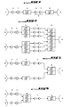
- Figures 5, 6 and 7 show the proposed functional diagram for a transponder that is capable of receiving signals from several service areas (two in this example), transmitting signals from either one of the two uplink service areas, or from both service areas, and for distributing those signals on the downlink side according to varying actual needs, by means of the invention.
- This functional diagram enables the advantages brought by the input multiplexer 10, while maintaining the possibility to allocate the full available bandwidth and power to either one of the two uplink service areas. This is additional flexibility in case the satellite designer does not know a priori whether one of the two uplink service areas might require the full resources.
- filters 4a and 4b have identical bandwidth characteristics; the spectrum associated to the passband of filters 4a and 4b corresponds to the envelope of the spectra associated to the passband covered by multiplexer 10.
- switches 11a and 11b at the input of filters 4a and 4b and multiplexer 10 are configured such that the transmitted signals are coming only from antenna 1a. The whole available spectrum and power are thus allocated to the service area corresponding to antenna 1a.
- switches 11a and 11b at the input of filters 4a and 4b and multiplexer 10 are configured such that the transmitted signals are coming only from antenna 1b. The whole available spectrum and power are thus allocated to the service area corresponding to antenna 1b.
- switches 11a and 11b at the input of filters 4a and 4b and multiplexer 10 are configured such that the transmitted signals are coming from both antenna 1a and antenna 1b, and combined through multiplexer 10.
- the spectrum and power are thus allocated to the service area corresponding to antenna 1b. Part of the spectrum is assigned to that service area associated to antenna 1a and another part of the spectrum is assigned to the other uplink service area associated to antenna 1a.
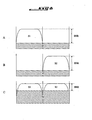
- Power addition also implies addition of the noise from all uplinks so that the uplink signal to noise ratio is reduced.
- G/T of each service area is similar, power combination of two service areas would degrade the G/T by typically 3 dB.
- A represents the spectrum of the signal from one service area
- B from the other
- C represents the spectrum after power addition of both signals.
- the uplink signal components are represented by S1 and S2, the noise by N and the signal to noise ratio as SNR. Note that the SNR in C is lower than the SNR in A and B.
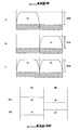
- the invention employs frequency multiplexing using filters, thus the name Uplink Frequency Multiplexing. This is shown in Figure 9 and Figure 10 .
- the spectrum SA assigned to one service area A corresponds to the passband pb of input filter FA, utilised with service area A while the spectrum SB assigned to the other service area B, corresponds to the stopband sb of the same input filter FA.
- Input filter FB for service area B is similarly specified. This scheme eliminates both disadvantages given above.
- the SNR in C is of the same order as the SNR in A and B.
Landscapes
- Engineering & Computer Science (AREA)
- Physics & Mathematics (AREA)
- Astronomy & Astrophysics (AREA)
- Aviation & Aerospace Engineering (AREA)
- General Physics & Mathematics (AREA)
- Computer Networks & Wireless Communication (AREA)
- Signal Processing (AREA)
- Radio Relay Systems (AREA)
- Noise Elimination (AREA)
Claims (5)
- Satellitengestützter Transponder für zwei oder mehrere Aufwärts-Versorgungsbereiche, umfassend zwei oder mehrere Empfangsketten (1a, 1b, 2, 3), die jeweils eine Aufwärtsantenne (1a, 1b), einen rauscharmen Verstärker (2) und einen Umformer (3), zwei oder mehrere Eingangsfilter (4), mindestens einen Eingangsmultiplexer (10), der mindestens ebenso viele Durchlassbereichfilter wie Empfangsketten aufweist, eine Verstärkungskette (5), die einen Kanalverstärker (6) und einen Hochleistungsverstärker (7) umfasst, und ein nachfolgendes Ausgangsfilter (8) und eine Abwärtsantenne (9) für einen verknüpften Abwärts-Versorgungsbereich, umfassen,
dadurch gekennzeichnet, dass er Mittel (11, 12) umfasst, um eine oder mehrere der zwei oder mehreren Empfangsketten (1a, 1b, 2, 3) jeweils mit einem entsprechenden Filter (4) oder mit dem Multiplexer (10) und entsprechend das Filter (4) oder den Multiplexer (10) mit der Verstärkungskette (5) zu verknüpfen, und dass jeder der Durchlassbereichfilter des Multiplexers (10) einen Durchlassbereich, der auf einen verknüpften Aufwärts-Versorgungsbereich eingestellt ist, und einen oder mehrere Sperrbereiche, die mit den anderen Aufwärts-Versorgungsbereichen verknüpft sind, aufweist. - Satellitengestützter Transponder nach Anspruch 1, dadurch gekennzeichnet, dass das Spektrum des Eingangsmultiplexers (10) mindestens in ebenso viele Teilspektren unterteilt ist wie Aufwärtsantennen (z.B. 1a, 1b) mit dem Multiplexer (10) verbunden sind, wobei die zusammengesetzten Durchlassbereiche aller Filter zusammen dem Spektrum des Eingangsmultiplexers (10) entsprechen, wobei dieser Eingangsmultiplexer an einen Hochleistungsverstärker (7) angeschlossen ist.
- Satellitengestützter Transponder nach Anspruch 1 oder 2, dadurch gekennzeichnet, dass er ebenso viele Eingangsfilter (4) und ebenso viele Schalter (11 und 12) wie Empfangsketten (1a, 1b, 2, 3) umfasst.
- Satellitengestützter Transponder nach einem der Ansprüche 1 bis 3, dadurch gekennzeichnet, dass die Filter (4) für jeden Aufwärts-Versorgungsbereich identische Bandbreitenkennzeichen aufweisen; wobei das mit dem Durchlassbereich der Filter (4a, 4b) verknüpfte Spektrum der Hüllkurve der Spektren entspricht, die mit dem Durchlassbereich verknüpft sind, der von dem Multiplexer (10) abgedeckt wird.
- Satelliten-Kommunikationssystem für zwei oder mehrere Aufwärts-Versorgungsbereiche, dadurch gekennzeichnet, dass es einen satellitengestützten Transponder nach einem der Ansprüche 1 bis 4 umfasst.
Priority Applications (1)
| Application Number | Priority Date | Filing Date | Title |
|---|---|---|---|
| EP08300124A EP1968212B1 (de) | 2007-02-28 | 2008-02-28 | Multiplexierung der Frequenzen einer Aufwärtsverbindung |
Applications Claiming Priority (2)
| Application Number | Priority Date | Filing Date | Title |
|---|---|---|---|
| EP07290256A EP1965511A1 (de) | 2007-02-28 | 2007-02-28 | Multiplexierung der Aufwärtsfrequenzen |
| EP08300124A EP1968212B1 (de) | 2007-02-28 | 2008-02-28 | Multiplexierung der Frequenzen einer Aufwärtsverbindung |
Publications (3)
| Publication Number | Publication Date |
|---|---|
| EP1968212A2 EP1968212A2 (de) | 2008-09-10 |
| EP1968212A3 EP1968212A3 (de) | 2008-10-01 |
| EP1968212B1 true EP1968212B1 (de) | 2010-06-02 |
Family
ID=38024333
Family Applications (2)
| Application Number | Title | Priority Date | Filing Date |
|---|---|---|---|
| EP07290256A Withdrawn EP1965511A1 (de) | 2007-02-28 | 2007-02-28 | Multiplexierung der Aufwärtsfrequenzen |
| EP08300124A Not-in-force EP1968212B1 (de) | 2007-02-28 | 2008-02-28 | Multiplexierung der Frequenzen einer Aufwärtsverbindung |
Family Applications Before (1)
| Application Number | Title | Priority Date | Filing Date |
|---|---|---|---|
| EP07290256A Withdrawn EP1965511A1 (de) | 2007-02-28 | 2007-02-28 | Multiplexierung der Aufwärtsfrequenzen |
Country Status (5)
| Country | Link |
|---|---|
| US (1) | US7869802B2 (de) |
| EP (2) | EP1965511A1 (de) |
| AT (1) | ATE470278T1 (de) |
| DE (1) | DE602008001390D1 (de) |
| ES (1) | ES2346937T3 (de) |
Families Citing this family (3)
| Publication number | Priority date | Publication date | Assignee | Title |
|---|---|---|---|---|
| US8660482B2 (en) * | 2010-10-14 | 2014-02-25 | Space Systems/Loral, Llc | Broadband satellite with dual frequency conversion and bandwidth aggregation |
| EP2629433A1 (de) * | 2012-02-16 | 2013-08-21 | Astrium Limited | Signalumwandlung in Kommunikationssatelliten |
| US9026043B2 (en) | 2012-04-16 | 2015-05-05 | Hughes Network Systems, Llc | System architecture for high density satellite capacity footprint with flexible antenna signal routing capabilities |
Family Cites Families (6)
| Publication number | Priority date | Publication date | Assignee | Title |
|---|---|---|---|---|
| US4931802A (en) * | 1988-03-11 | 1990-06-05 | Communications Satellite Corporation | Multiple spot-beam systems for satellite communications |
| GB8819501D0 (en) * | 1988-08-17 | 1988-09-21 | British Aerospace | Spacecraft payload |
| US6173155B1 (en) * | 1997-10-17 | 2001-01-09 | Hughes Electronics Corporation | Method and apparatus for spacecraft amplification of multi-channel signals |
| FR2783377A1 (fr) * | 1998-09-14 | 2000-03-17 | Loral Space Systems Inc | Systeme de communications par satellite ameliore utilisant des multiplexeurs d'entree hf depuis une pluralite de faisceaux ponctuels vers un recepteur |
| US6571081B1 (en) * | 1999-05-04 | 2003-05-27 | Hughes Electronics Corporation | Hybridized space/ground beam forming |
| US6606055B2 (en) * | 2000-12-06 | 2003-08-12 | Harris Corporation | Phased array communication system providing airborne crosslink and satellite communication receive capability |
-
2007
- 2007-02-28 EP EP07290256A patent/EP1965511A1/de not_active Withdrawn
-
2008
- 2008-02-28 ES ES08300124T patent/ES2346937T3/es active Active
- 2008-02-28 DE DE602008001390T patent/DE602008001390D1/de active Active
- 2008-02-28 US US12/039,169 patent/US7869802B2/en not_active Expired - Fee Related
- 2008-02-28 AT AT08300124T patent/ATE470278T1/de not_active IP Right Cessation
- 2008-02-28 EP EP08300124A patent/EP1968212B1/de not_active Not-in-force
Also Published As
| Publication number | Publication date |
|---|---|
| US7869802B2 (en) | 2011-01-11 |
| ATE470278T1 (de) | 2010-06-15 |
| EP1968212A2 (de) | 2008-09-10 |
| US20080207118A1 (en) | 2008-08-28 |
| EP1968212A3 (de) | 2008-10-01 |
| ES2346937T3 (es) | 2010-10-21 |
| EP1965511A1 (de) | 2008-09-03 |
| DE602008001390D1 (de) | 2010-07-15 |
Similar Documents
| Publication | Publication Date | Title |
|---|---|---|
| US10454567B2 (en) | Multi-beam satellite communication system | |
| US10404354B2 (en) | Methods and systems for improving spectrum utilization for satellite communications | |
| US6175719B1 (en) | Multi-spot-beam satellite system with broadcast and surge capacity capability | |
| EP2442460B1 (de) | Flexible Abdeckungsbereiche für Rückwärtsverbindungssignale in einem Spotbeam-Satellitenkommunikationssystem | |
| CA2514959C (en) | Systems and methods for digital processing of satellite communications data | |
| US9252869B2 (en) | Satellite telecommunications system for providing star traffic and mesh traffic | |
| CA2157209C (en) | Repeaters for multibeam satellites | |
| CA2250427C (en) | Method and system for reducing multipath fading in bent-pipe satellite communications systems | |
| EP1328073A2 (de) | Ausführung einer Zwischenfrequenz-Transpondernutzlast | |
| US5033108A (en) | Signal repeater using shared amplification with selectable input/output connections | |
| EP0788246A2 (de) | Auf einen geosynchronen Satelliten zentrierte Kommunikationsanordnung | |
| US9979466B2 (en) | Reverse wireless broadband system | |
| US7869802B2 (en) | Uplink frequency multiplexing system | |
| EP1439641B1 (de) | Gerät und Verfahren zum Betrieb eines bidirektionalen Transponders | |
| US8340573B2 (en) | Payload system for satellites | |
| CA2883278C (en) | Methods and systems for improving spectrum utilization for satellite communications | |
| EP0760561B1 (de) | Satelliten-Zwischenverstärker zur Funkkeulen-Umschaltung von Kanälen und Teilkanälen | |
| JP2001196992A (ja) | 衛星通信システム | |
| US7280523B2 (en) | Signal processing apparatus and method, and communication system utilizing same |
Legal Events
| Date | Code | Title | Description |
|---|---|---|---|
| PUAI | Public reference made under article 153(3) epc to a published international application that has entered the european phase |
Free format text: ORIGINAL CODE: 0009012 |
|
| PUAL | Search report despatched |
Free format text: ORIGINAL CODE: 0009013 |
|
| AK | Designated contracting states |
Kind code of ref document: A2 Designated state(s): AT BE BG CH CY CZ DE DK EE ES FI FR GB GR HR HU IE IS IT LI LT LU LV MC MT NL NO PL PT RO SE SI SK TR |
|
| AX | Request for extension of the european patent |
Extension state: AL BA MK RS |
|
| AK | Designated contracting states |
Kind code of ref document: A3 Designated state(s): AT BE BG CH CY CZ DE DK EE ES FI FR GB GR HR HU IE IS IT LI LT LU LV MC MT NL NO PL PT RO SE SI SK TR |
|
| AX | Request for extension of the european patent |
Extension state: AL BA MK RS |
|
| RIN1 | Information on inventor provided before grant (corrected) |
Inventor name: FENECH, HECTOR Inventor name: LANCE, EMMANUEL |
|
| 17P | Request for examination filed |
Effective date: 20090304 |
|
| 17Q | First examination report despatched |
Effective date: 20090504 |
|
| AKX | Designation fees paid |
Designated state(s): AT BE BG CH CY CZ DE DK EE ES FI FR GB GR HR HU IE IS IT LI LT LU LV MC MT NL NO PL PT RO SE SI SK TR |
|
| GRAP | Despatch of communication of intention to grant a patent |
Free format text: ORIGINAL CODE: EPIDOSNIGR1 |
|
| GRAS | Grant fee paid |
Free format text: ORIGINAL CODE: EPIDOSNIGR3 |
|
| GRAA | (expected) grant |
Free format text: ORIGINAL CODE: 0009210 |
|
| AK | Designated contracting states |
Kind code of ref document: B1 Designated state(s): AT BE BG CH CY CZ DE DK EE ES FI FR GB GR HR HU IE IS IT LI LT LU LV MC MT NL NO PL PT RO SE SI SK TR |
|
| REG | Reference to a national code |
Ref country code: GB Ref legal event code: FG4D |
|
| REG | Reference to a national code |
Ref country code: CH Ref legal event code: EP |
|
| REG | Reference to a national code |
Ref country code: IE Ref legal event code: FG4D |
|
| REF | Corresponds to: |
Ref document number: 602008001390 Country of ref document: DE Date of ref document: 20100715 Kind code of ref document: P |
|
| REG | Reference to a national code |
Ref country code: NL Ref legal event code: T3 |
|
| REG | Reference to a national code |
Ref country code: SE Ref legal event code: TRGR |
|
| REG | Reference to a national code |
Ref country code: ES Ref legal event code: FG2A Ref document number: 2346937 Country of ref document: ES Kind code of ref document: T3 |
|
| PG25 | Lapsed in a contracting state [announced via postgrant information from national office to epo] |
Ref country code: LT Free format text: LAPSE BECAUSE OF FAILURE TO SUBMIT A TRANSLATION OF THE DESCRIPTION OR TO PAY THE FEE WITHIN THE PRESCRIBED TIME-LIMIT Effective date: 20100602 |
|
| REG | Reference to a national code |
Ref country code: NO Ref legal event code: T2 Effective date: 20100602 |
|
| LTIE | Lt: invalidation of european patent or patent extension |
Effective date: 20100602 |
|
| PG25 | Lapsed in a contracting state [announced via postgrant information from national office to epo] |
Ref country code: AT Free format text: LAPSE BECAUSE OF FAILURE TO SUBMIT A TRANSLATION OF THE DESCRIPTION OR TO PAY THE FEE WITHIN THE PRESCRIBED TIME-LIMIT Effective date: 20100602 Ref country code: SI Free format text: LAPSE BECAUSE OF FAILURE TO SUBMIT A TRANSLATION OF THE DESCRIPTION OR TO PAY THE FEE WITHIN THE PRESCRIBED TIME-LIMIT Effective date: 20100602 Ref country code: LV Free format text: LAPSE BECAUSE OF FAILURE TO SUBMIT A TRANSLATION OF THE DESCRIPTION OR TO PAY THE FEE WITHIN THE PRESCRIBED TIME-LIMIT Effective date: 20100602 Ref country code: HR Free format text: LAPSE BECAUSE OF FAILURE TO SUBMIT A TRANSLATION OF THE DESCRIPTION OR TO PAY THE FEE WITHIN THE PRESCRIBED TIME-LIMIT Effective date: 20100602 Ref country code: FI Free format text: LAPSE BECAUSE OF FAILURE TO SUBMIT A TRANSLATION OF THE DESCRIPTION OR TO PAY THE FEE WITHIN THE PRESCRIBED TIME-LIMIT Effective date: 20100602 |
|
| PG25 | Lapsed in a contracting state [announced via postgrant information from national office to epo] |
Ref country code: PL Free format text: LAPSE BECAUSE OF FAILURE TO SUBMIT A TRANSLATION OF THE DESCRIPTION OR TO PAY THE FEE WITHIN THE PRESCRIBED TIME-LIMIT Effective date: 20100602 Ref country code: CY Free format text: LAPSE BECAUSE OF FAILURE TO SUBMIT A TRANSLATION OF THE DESCRIPTION OR TO PAY THE FEE WITHIN THE PRESCRIBED TIME-LIMIT Effective date: 20100602 |
|
| PG25 | Lapsed in a contracting state [announced via postgrant information from national office to epo] |
Ref country code: EE Free format text: LAPSE BECAUSE OF FAILURE TO SUBMIT A TRANSLATION OF THE DESCRIPTION OR TO PAY THE FEE WITHIN THE PRESCRIBED TIME-LIMIT Effective date: 20100602 |
|
| PG25 | Lapsed in a contracting state [announced via postgrant information from national office to epo] |
Ref country code: RO Free format text: LAPSE BECAUSE OF FAILURE TO SUBMIT A TRANSLATION OF THE DESCRIPTION OR TO PAY THE FEE WITHIN THE PRESCRIBED TIME-LIMIT Effective date: 20100602 Ref country code: SK Free format text: LAPSE BECAUSE OF FAILURE TO SUBMIT A TRANSLATION OF THE DESCRIPTION OR TO PAY THE FEE WITHIN THE PRESCRIBED TIME-LIMIT Effective date: 20100602 Ref country code: CZ Free format text: LAPSE BECAUSE OF FAILURE TO SUBMIT A TRANSLATION OF THE DESCRIPTION OR TO PAY THE FEE WITHIN THE PRESCRIBED TIME-LIMIT Effective date: 20100602 Ref country code: IS Free format text: LAPSE BECAUSE OF FAILURE TO SUBMIT A TRANSLATION OF THE DESCRIPTION OR TO PAY THE FEE WITHIN THE PRESCRIBED TIME-LIMIT Effective date: 20101002 |
|
| PLBE | No opposition filed within time limit |
Free format text: ORIGINAL CODE: 0009261 |
|
| STAA | Information on the status of an ep patent application or granted ep patent |
Free format text: STATUS: NO OPPOSITION FILED WITHIN TIME LIMIT |
|
| PG25 | Lapsed in a contracting state [announced via postgrant information from national office to epo] |
Ref country code: DK Free format text: LAPSE BECAUSE OF FAILURE TO SUBMIT A TRANSLATION OF THE DESCRIPTION OR TO PAY THE FEE WITHIN THE PRESCRIBED TIME-LIMIT Effective date: 20100602 |
|
| 26N | No opposition filed |
Effective date: 20110303 |
|
| PG25 | Lapsed in a contracting state [announced via postgrant information from national office to epo] |
Ref country code: GR Free format text: LAPSE BECAUSE OF FAILURE TO SUBMIT A TRANSLATION OF THE DESCRIPTION OR TO PAY THE FEE WITHIN THE PRESCRIBED TIME-LIMIT Effective date: 20100903 |
|
| REG | Reference to a national code |
Ref country code: DE Ref legal event code: R097 Ref document number: 602008001390 Country of ref document: DE Effective date: 20110302 |
|
| PG25 | Lapsed in a contracting state [announced via postgrant information from national office to epo] |
Ref country code: MC Free format text: LAPSE BECAUSE OF NON-PAYMENT OF DUE FEES Effective date: 20110228 |
|
| REG | Reference to a national code |
Ref country code: IE Ref legal event code: MM4A |
|
| PG25 | Lapsed in a contracting state [announced via postgrant information from national office to epo] |
Ref country code: MT Free format text: LAPSE BECAUSE OF FAILURE TO SUBMIT A TRANSLATION OF THE DESCRIPTION OR TO PAY THE FEE WITHIN THE PRESCRIBED TIME-LIMIT Effective date: 20100602 |
|
| PG25 | Lapsed in a contracting state [announced via postgrant information from national office to epo] |
Ref country code: IE Free format text: LAPSE BECAUSE OF NON-PAYMENT OF DUE FEES Effective date: 20110228 |
|
| REG | Reference to a national code |
Ref country code: CH Ref legal event code: PL |
|
| PG25 | Lapsed in a contracting state [announced via postgrant information from national office to epo] |
Ref country code: LI Free format text: LAPSE BECAUSE OF NON-PAYMENT OF DUE FEES Effective date: 20120229 Ref country code: CH Free format text: LAPSE BECAUSE OF NON-PAYMENT OF DUE FEES Effective date: 20120229 |
|
| PG25 | Lapsed in a contracting state [announced via postgrant information from national office to epo] |
Ref country code: LU Free format text: LAPSE BECAUSE OF NON-PAYMENT OF DUE FEES Effective date: 20110228 |
|
| PG25 | Lapsed in a contracting state [announced via postgrant information from national office to epo] |
Ref country code: PT Free format text: LAPSE BECAUSE OF NON-PAYMENT OF DUE FEES Effective date: 20100602 |
|
| PG25 | Lapsed in a contracting state [announced via postgrant information from national office to epo] |
Ref country code: BG Free format text: LAPSE BECAUSE OF FAILURE TO SUBMIT A TRANSLATION OF THE DESCRIPTION OR TO PAY THE FEE WITHIN THE PRESCRIBED TIME-LIMIT Effective date: 20100902 Ref country code: TR Free format text: LAPSE BECAUSE OF FAILURE TO SUBMIT A TRANSLATION OF THE DESCRIPTION OR TO PAY THE FEE WITHIN THE PRESCRIBED TIME-LIMIT Effective date: 20100602 |
|
| PG25 | Lapsed in a contracting state [announced via postgrant information from national office to epo] |
Ref country code: HU Free format text: LAPSE BECAUSE OF FAILURE TO SUBMIT A TRANSLATION OF THE DESCRIPTION OR TO PAY THE FEE WITHIN THE PRESCRIBED TIME-LIMIT Effective date: 20100602 |
|
| REG | Reference to a national code |
Ref country code: FR Ref legal event code: PLFP Year of fee payment: 8 |
|
| REG | Reference to a national code |
Ref country code: FR Ref legal event code: PLFP Year of fee payment: 9 |
|
| REG | Reference to a national code |
Ref country code: FR Ref legal event code: PLFP Year of fee payment: 10 |
|
| PGFP | Annual fee paid to national office [announced via postgrant information from national office to epo] |
Ref country code: NL Payment date: 20170123 Year of fee payment: 10 |
|
| PGFP | Annual fee paid to national office [announced via postgrant information from national office to epo] |
Ref country code: FR Payment date: 20170124 Year of fee payment: 10 Ref country code: SE Payment date: 20170124 Year of fee payment: 10 Ref country code: DE Payment date: 20170119 Year of fee payment: 10 Ref country code: NO Payment date: 20170124 Year of fee payment: 10 |
|
| PGFP | Annual fee paid to national office [announced via postgrant information from national office to epo] |
Ref country code: GB Payment date: 20170124 Year of fee payment: 10 Ref country code: BE Payment date: 20170119 Year of fee payment: 10 |
|
| PGFP | Annual fee paid to national office [announced via postgrant information from national office to epo] |
Ref country code: IT Payment date: 20170120 Year of fee payment: 10 Ref country code: ES Payment date: 20170123 Year of fee payment: 10 |
|
| REG | Reference to a national code |
Ref country code: DE Ref legal event code: R119 Ref document number: 602008001390 Country of ref document: DE |
|
| REG | Reference to a national code |
Ref country code: NO Ref legal event code: MMEP |
|
| REG | Reference to a national code |
Ref country code: NL Ref legal event code: MM Effective date: 20180301 |
|
| GBPC | Gb: european patent ceased through non-payment of renewal fee |
Effective date: 20180228 |
|
| PG25 | Lapsed in a contracting state [announced via postgrant information from national office to epo] |
Ref country code: SE Free format text: LAPSE BECAUSE OF NON-PAYMENT OF DUE FEES Effective date: 20180301 Ref country code: NO Free format text: LAPSE BECAUSE OF NON-PAYMENT OF DUE FEES Effective date: 20180228 |
|
| REG | Reference to a national code |
Ref country code: BE Ref legal event code: MM Effective date: 20180228 |
|
| REG | Reference to a national code |
Ref country code: FR Ref legal event code: ST Effective date: 20181031 |
|
| PG25 | Lapsed in a contracting state [announced via postgrant information from national office to epo] |
Ref country code: NL Free format text: LAPSE BECAUSE OF NON-PAYMENT OF DUE FEES Effective date: 20180301 |
|
| PG25 | Lapsed in a contracting state [announced via postgrant information from national office to epo] |
Ref country code: DE Free format text: LAPSE BECAUSE OF NON-PAYMENT OF DUE FEES Effective date: 20180901 |
|
| PG25 | Lapsed in a contracting state [announced via postgrant information from national office to epo] |
Ref country code: GB Free format text: LAPSE BECAUSE OF NON-PAYMENT OF DUE FEES Effective date: 20180228 Ref country code: BE Free format text: LAPSE BECAUSE OF NON-PAYMENT OF DUE FEES Effective date: 20180228 Ref country code: IT Free format text: LAPSE BECAUSE OF NON-PAYMENT OF DUE FEES Effective date: 20180228 Ref country code: FR Free format text: LAPSE BECAUSE OF NON-PAYMENT OF DUE FEES Effective date: 20180228 |
|
| REG | Reference to a national code |
Ref country code: ES Ref legal event code: FD2A Effective date: 20190801 |
|
| PG25 | Lapsed in a contracting state [announced via postgrant information from national office to epo] |
Ref country code: ES Free format text: LAPSE BECAUSE OF NON-PAYMENT OF DUE FEES Effective date: 20180228 |