EP1968201A1 - Predistortion with asymmetric usage of available bandwidth - Google Patents
Predistortion with asymmetric usage of available bandwidth Download PDFInfo
- Publication number
- EP1968201A1 EP1968201A1 EP07290309A EP07290309A EP1968201A1 EP 1968201 A1 EP1968201 A1 EP 1968201A1 EP 07290309 A EP07290309 A EP 07290309A EP 07290309 A EP07290309 A EP 07290309A EP 1968201 A1 EP1968201 A1 EP 1968201A1
- Authority
- EP
- European Patent Office
- Prior art keywords
- signal
- predistortion
- intermodulation distortion
- window
- radio frequency
- Prior art date
- Legal status (The legal status is an assumption and is not a legal conclusion. Google has not performed a legal analysis and makes no representation as to the accuracy of the status listed.)
- Withdrawn
Links
Images


Classifications
-
- H—ELECTRICITY
- H04—ELECTRIC COMMUNICATION TECHNIQUE
- H04B—TRANSMISSION
- H04B1/00—Details of transmission systems, not covered by a single one of groups H04B3/00 - H04B13/00; Details of transmission systems not characterised by the medium used for transmission
- H04B1/02—Transmitters
- H04B1/04—Circuits
- H04B1/0475—Circuits with means for limiting noise, interference or distortion
-
- H—ELECTRICITY
- H03—ELECTRONIC CIRCUITRY
- H03F—AMPLIFIERS
- H03F1/00—Details of amplifiers with only discharge tubes, only semiconductor devices or only unspecified devices as amplifying elements
- H03F1/32—Modifications of amplifiers to reduce non-linear distortion
- H03F1/3241—Modifications of amplifiers to reduce non-linear distortion using predistortion circuits
-
- H—ELECTRICITY
- H04—ELECTRIC COMMUNICATION TECHNIQUE
- H04B—TRANSMISSION
- H04B1/00—Details of transmission systems, not covered by a single one of groups H04B3/00 - H04B13/00; Details of transmission systems not characterised by the medium used for transmission
- H04B1/02—Transmitters
- H04B1/04—Circuits
- H04B2001/0408—Circuits with power amplifiers
- H04B2001/0425—Circuits with power amplifiers with linearisation using predistortion
Definitions
- the invention relates to a method for performing predistortion of a radio frequency signal, a power amplifier for amplifying a wanted signal comprising means for predistortion of a radio frequency signal, a mobile telecommunications system comprising an amplifier comprising means for predistortion with asymmetric usage, a mobile phone comprising a power amplifier comprising means for predistortion with asymmetric usage of available bandwidth and a computer program product comprising executable instructions for performing predistortion with asymmetric usage of available bandwidth.
- the disadvantage of operating a power amplifier near to saturation is that due to the amplifier non-linearity a resultant amplified signal comprises besides the amplified wanted signal intermodulation distortion signals located at frequencies above and at frequencies below the desired wanted output signal.
- Intermodulation distortion is highly undesirable, because it causes interference, cross talk and other effects which need to be suppressed in order to comply with requirements regarding transmitted signals in for example mobile communication systems.
- intermodulation distortion can be reduced by different power amplifier linearization methods which can be classified mainly as feedback, feed forward and predistortion.
- predistortion is known to be a complicated linearization method applicable in telecommunication base stations, where extremely high linearity is required, it has been shown that with a careful design it is also applicable in handsets resulting in significant linearity improvement.
- the concept of the predistortion technique is to insert a non-linear module between the input signal and the power amplifier.
- the non-linear module generates intermodulation distortion products, that are in anti phase with the intermodular distortion products produced by the power amplifier, reducing out of band emissions.
- the predistortion circuit inversely models the amplifier's gain and phase characteristics and, when combined with the amplifier, produces an overall system that is more linear. Therewith, out of band emissions generated by the amplifier can be drastically reduced.
- US 5,877,653 discloses a linear power amplifier and method for removing the intermodulation distortion with a predistortion system and a feed forward system.
- US 6,757,338 discloses a predistortion linearizer for predistorting a radio frequency signal.
- the present invention provides a method for performing predistortion of a radio frequency signal, said radio frequency signal comprising a wanted signal and a first and a second intermodulation distortion signal sideband, comprising the steps of defining a predistortion window, positioning said predistortion window asymmetrically around said radio frequency signal and predistorting said radio frequency signal within the positioned predistortion window.
- the predistortion window is preferably positioned including the wanted signal and a first intermodulation distortion signal.
- the method for performing predistortion of a radio frequency signal allows to use predistortion circuits with a considerably smaller bandwidth, since predistortion is not applied anymore to the full bandwidth of the amplified signal.
- predistortion is exclusively performed on one side above or below the centre frequency of the wanted signal, which allows to even suppress spectral intermodulation components of third, fifth and higher order.
- a limited predistortion bandwidth leads, due to lower technical demands on respective components, to considerable cost savings.
- the method for performing predistortion of a radio frequency signal further comprises determining predistortion parameters to be applied to the second intermodulation distortion signal, whereby said determination is based on analysis of the first intermodulation distortion signal.
- Correlation of the spectral components of one side of the wanted signal can be described mathematically due to known physical effects. Thereby, by focusing on one side of the disturbing spectrum only, physical information for predistortion of both sides of disturbing spectrum can be obtained. Therefore, a limited detection bandwidth can be used to achieve a better spectral predistortion achievement for a high bandwidth on both frequency sides of the desired output signal.
- the position of the predistortion window is determined based on spectral output signal requirements of the intermodulation distortion signal sidebands. Since the spectral output signal requirements can be different for frequencies above and below the desired output signal, this allows to perform highly effective predistortion on the side of the spectrum with the higher spectral output signal requirements, whereas for the opposite side with lower spectral output signal requirements mathematical methods can be applied to predistort intermodulation signals on said side.
- the invention in another aspect, relates to a power amplifier for amplifying a wanted signal, the power amplifier comprising input means for receiving the wanted signal, output means for providing an amplified output signal, the output signal comprising an amplified wanted signal and a first and a second intermodulation distortion signal, means for defining a predistortion window, means for positioning said predistortion window asymmetrically around the amplified wanted signal and means for predistorting the amplified wanted signal within the positioned predistortion window.
- the power amplifier further comprises means for determining predistortion parameters to be applied to the second intermodulation distortion signal, whereby the determination is based on analysis of the first intermodulation distortion signal.
- the invention in another aspect relates to a mobile telecommunication system comprising a power amplifier according to the invention.
- the invention in another aspect relates to a mobile telecommunications base station comprising power amplifier according to the invention.
- the base station is a GSM, UMTS, WiMAX or LTE base station.
- the invention in another aspect relates to a mobile phone comprising a power amplifier according to the invention.
- the invention in another aspect relates to a computer program product comprising executable instructions for performing the method for performing predistortion of a radio frequency signal.
- Fig. 1 is a block diagram of an embodiment of a power amplifier 104 comprising predistortion means according to the invention.
- a wanted signal 102 which is generated by for example a base station or a mobile phone 100 is inputted to the amplifier unit 104 with means of an interface 106.
- the width of a predistortion window is set.
- the means 110 for positioning the predistortion window are used to position the predistortion window asymmetrically around said radio frequency signal.
- the predistortion window is preferably positioned including the wanted signal and a first intermodulation distortion signal which is output by the power amplifier 116.
- Means 112 which are adapted for signal predistortion are used to predistort the signal within the asymmetrically positioned predistortion window.
- the predistorted signal is amplified by the power amplifier 116 and transmitted to an antenna 120 using an interface 118.
- the amplified signal output by the power amplifier 116 also comprises a second intermodulation distortion signal, whereby the first and the second intermodulation distortion signals are located symmetrically at frequencies below and above the desired output signal.
- the spectral components of one side, either above or below the desired signal are correlated to the spectral components of the other side, for example due to physical effects which can be described using mathematical methods. Therefore, the means 114 are adapted for calculating predistortion parameters based on the intermodulation distortion signal on one frequency side of the desired output signal.
- the calculated parameters are used to additionally predistort the signal to be inputted to the power amplifier 116. Therewith, any non-linearity the amplifier might possess is cancelled. This way, the power amplifier can be operated effectively near saturation where it is highly non-linear but extremely efficient.
- Memory effects can for example develop due to modulation signals with different bandwidth which may generate a modulation signal dependent amplification behavior of the amplifier 116.
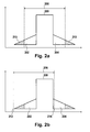
- Figs. 2a to 2d show schematics illustrating the signal predistortion method according to the invention.
- fig. 2a shows a state of the art predistortion technique.
- a wanted radio frequency signal 200, as well as a first intermodulation distortion signal 202 at a frequency below the wanted signal and a second intermodulation distortion signal 204 above the desired wanted signal 200 are generated by amplification of a radio frequency signal by means of a power amplifier.
- Predistortion is applied on the combined signal comprising the wanted signal 200 and the intermodulation distortion signals 202 and 204.
- predistortion can only be incompletely performed within a spectrally limited window of a bandwidth 206.
- said predistortion window 206 is applied asymmetrically to the output signal of the power amplifier.
- the predistortion window 206 is positioned including the wanted signal 200 and the complete first intermodulation distortion signal 202.
- the low frequency side 212 of the predistortion window 206 also covers higher order (3 rd , 5 th , 7 th ) intermodulation distortion signals.
- the high frequency side 214 of the predistortion window 206 only covers a rather limited part of the second intermodulation distortion signal 204.
- the reasons for preferably positioning the predistortion window 206 asymmetrically on the low frequency side of the wanted signal 200 could be for example special spectral output signal requirements of the intermodulation distortion signal sidebands, which have higher demands on the low frequency side of an output signal compared to the high frequency side of an output signal.
- Fig. 2c shows the signal which has been predistorted within the predistortion window 206.
- the amplitude of the first intermodulation distortion signal 202 is drastically reduced.
- Such amplitude reduction can for example be performed by either negative feedback of the distorted signal or by separating distortion components of the amplifier output and feeding the distortion components forward to cancel the distortion in the amplified output signal.
- predistortion can be realized in two different ways, namely analogue or digital implementation.
- Analogue predistortion can be realized by creating the required non-linearities cancelling effects of the power amplifier using analogue components.
- the system is realized with digital components.
- Analogue predistortion can be implemented at RF, IF or baseband, whereas typically digital predistortion is implemented at the baseband.
- predistortion parameters are determined based on analysis of the first intermodulation distortion signal. Therewith, by only analyzing the first intermodulation distortion signal 202, the second intermodulation distortion signal 204 can be predistorted by applying said parameters.
- Fig. 2d shows the power amplifier output after combined predistortion of the first intermodulation distortion signal 202 and the second intermodulation distortion signal 204, whereby the predistortion parameters for the second intermodulation distortion signal 204 were calculated based on analysis of the first intermodulation distortion signal 202.
- the predistortion window 206 is positioned asymmetrically around the wanted signal 200 including mainly the first intermodulation distortion signal 202 and the wanted signal 200, a full suppression of said intermodulation distortion signals can be obtained.
- Fig. 3 shows a flowchart illustrating a method for performing the predistortion method according to the invention.
- a predistortion window is defined. Definition of the predistortion window thereby comprises defining the width of said predistortion window.
- the predistortion window is positioned asymmetrically around the wanted signal. Thereby the predistortion window is preferably positioned including the wanted signal and the first intermodulation distortion signal, whereby the position of the predistortion window is determined based on spectral output signal requirements of the intermodulation distortion signal sidebands.
- step 304 based on analysis of the signal comprised within the predistortion window, the signal is predistorted. However, since this only comprises predistortion of the first intermodulation distortion signal, additional predistortion parameters are calculated in step 306, whereby said parameters are indicative of the spectral characteristics of the second intermodulation distortion signal not covered by the predistortion window. Based on said calculated parameters, the signal is predistorted in step 308. Typically, steps 304 and 308 are performed in one combined predistortion step.
- Fig. 4 shows a block diagram illustrating an embodiment of a predistortion unit 700 and an amplifier unit 704.
- the predistortion unit 700 predistorts the digital input signal 702 in order to compensate the non-linear properties of the amplifier unit 704.
- the input signal 702 comprises in phase and quadrature signals.
- a digital analogue converter used to transform digital signals into analogue signals.
- a frequency translator 706 is used to translate the input signals to their transmit radio frequency.
- the radio frequency signal is then input into a power amplifier 708.
- the amplifier unit 704, which comprises the power amplifier 708, further comprises a coupler 710.
- the coupler 710 is used for coupling out a small portion of the transmit radio frequency signal for the purpose of analysis by the predistortion unit 700.
- the coupled out signal is fed into a mixer 714, which translates the transmit frequency into an intermediate frequency.
- the predistortion bandwidth is thereby located within the intermediate frequency bandwith.
- the mixer 714 as well as the means for signal filtering and amplification of the signal at intermediate frequency are comprised within a feedback path 718.
- the signal Before transmission of the signal from the feedback path 718 to the predistortion unit 700, the signal is sampled with an analogue digital converter and converted into digital in phase and quadrature signals. Thereby, the properties of the analogue digital converter are essential for the choice of the predistortion bandwidth.
- the predistortion unit 700 comprises means for defining and positioning the predistortion window, as well as means for determining predistortion parameters to be applied to a second intermodulation distortion signal. Said determination is based on analysis of a first intermodulation distortion signal, whereby the radio frequency signal fed into the predistortion unit 700 with means of the feedback path 718 comprises both, a wanted signal and the first and second intermodulation distortion signals.
- the amplifier unit 704 further comprises an isolator 712, which can also be adapted as a circulator.
- the isolator 712 is located at the output of the amplifier 708.
- the purpose of the isolator 712 is the maintenance of a constant impedance level which is essential for protection of final stage transistors (not shown here) from signals being reflected from for example defect cables to the antenna 716.
Abstract
- defining a predistortion window,
- positioning said predistortion window asymmetrically around said radio frequency signal,
- predistorting said radio frequency signal within the positioned predistortion window.
Description
- The invention relates to a method for performing predistortion of a radio frequency signal, a power amplifier for amplifying a wanted signal comprising means for predistortion of a radio frequency signal, a mobile telecommunications system comprising an amplifier comprising means for predistortion with asymmetric usage, a mobile phone comprising a power amplifier comprising means for predistortion with asymmetric usage of available bandwidth and a computer program product comprising executable instructions for performing predistortion with asymmetric usage of available bandwidth.
- Active linearization has become an important technology in modern communication systems. In new generation mobile communication systems where spectrum efficient linear modulation formats are used, power amplifier linearity is a key requirement. Typically, power amplifiers are operated near to saturation where they are highly efficient but extremely non-linear.
- Therefore, the disadvantage of operating a power amplifier near to saturation is that due to the amplifier non-linearity a resultant amplified signal comprises besides the amplified wanted signal intermodulation distortion signals located at frequencies above and at frequencies below the desired wanted output signal. Intermodulation distortion is highly undesirable, because it causes interference, cross talk and other effects which need to be suppressed in order to comply with requirements regarding transmitted signals in for example mobile communication systems.
- Generally, intermodulation distortion can be reduced by different power amplifier linearization methods which can be classified mainly as feedback, feed forward and predistortion. Even though, predistortion is known to be a complicated linearization method applicable in telecommunication base stations, where extremely high linearity is required, it has been shown that with a careful design it is also applicable in handsets resulting in significant linearity improvement.
- The concept of the predistortion technique is to insert a non-linear module between the input signal and the power amplifier. The non-linear module generates intermodulation distortion products, that are in anti phase with the intermodular distortion products produced by the power amplifier, reducing out of band emissions. This means, that the input signal is expanded prior to a power amplifier in such a way, that the non-linearities generated by the power amplifier are compensated. The predistortion circuit inversely models the amplifier's gain and phase characteristics and, when combined with the amplifier, produces an overall system that is more linear. Therewith, out of band emissions generated by the amplifier can be drastically reduced.
- There are known methods for performing predistortion to improve the linearity of radio transmitter power amplifiers. For example
US 5,877,653 discloses a linear power amplifier and method for removing the intermodulation distortion with a predistortion system and a feed forward system.US 6,757,338 discloses a predistortion linearizer for predistorting a radio frequency signal. - However, such predistortion techniques typically apply predistortion to a rather large signal bandwidth comprising both, the wanted signal and the intermodulation signals at frequencies below and above the desired output signal. This has the disadvantage, that high bandwidth predistortion circuits are required, which is rather cost intensive. Also, operation of such high-bandwidth circuits is rather power consuming. Another disadvantage is, that due to the still limited bandwidth of such highly sophisticated predistortion circuits it is rather impossible to predistort an amplified signal regarding its whole broad frequency bandwidth.
- The present invention provides a method for performing predistortion of a radio frequency signal, said radio frequency signal comprising a wanted signal and a first and a second intermodulation distortion signal sideband, comprising the steps of defining a predistortion window, positioning said predistortion window asymmetrically around said radio frequency signal and predistorting said radio frequency signal within the positioned predistortion window. Thereby, the predistortion window is preferably positioned including the wanted signal and a first intermodulation distortion signal.
- The method for performing predistortion of a radio frequency signal according to the invention allows to use predistortion circuits with a considerably smaller bandwidth, since predistortion is not applied anymore to the full bandwidth of the amplified signal. In contrary, predistortion is exclusively performed on one side above or below the centre frequency of the wanted signal, which allows to even suppress spectral intermodulation components of third, fifth and higher order. Further, a limited predistortion bandwidth leads, due to lower technical demands on respective components, to considerable cost savings.
- In an embodiment of the invention, the method for performing predistortion of a radio frequency signal further comprises determining predistortion parameters to be applied to the second intermodulation distortion signal, whereby said determination is based on analysis of the first intermodulation distortion signal. This has the advantage, that upon knowledge of only the first intermodulation distortion signal, a respective second intermodulation distortion signal can be theoretically calculated and predistortion can be applied to both, the first and to second intermodulation distortion signals.
- Correlation of the spectral components of one side of the wanted signal can be described mathematically due to known physical effects. Thereby, by focusing on one side of the disturbing spectrum only, physical information for predistortion of both sides of disturbing spectrum can be obtained. Therefore, a limited detection bandwidth can be used to achieve a better spectral predistortion achievement for a high bandwidth on both frequency sides of the desired output signal.
- In accordance with an embodiment of the invention, the position of the predistortion window is determined based on spectral output signal requirements of the intermodulation distortion signal sidebands. Since the spectral output signal requirements can be different for frequencies above and below the desired output signal, this allows to perform highly effective predistortion on the side of the spectrum with the higher spectral output signal requirements, whereas for the opposite side with lower spectral output signal requirements mathematical methods can be applied to predistort intermodulation signals on said side.
- In another aspect, the invention relates to a power amplifier for amplifying a wanted signal, the power amplifier comprising input means for receiving the wanted signal, output means for providing an amplified output signal, the output signal comprising an amplified wanted signal and a first and a second intermodulation distortion signal, means for defining a predistortion window, means for positioning said predistortion window asymmetrically around the amplified wanted signal and means for predistorting the amplified wanted signal within the positioned predistortion window.
- In accordance with an embodiment of the invention, the power amplifier further comprises means for determining predistortion parameters to be applied to the second intermodulation distortion signal, whereby the determination is based on analysis of the first intermodulation distortion signal.
- In another aspect the invention relates to a mobile telecommunication system comprising a power amplifier according to the invention.
- In another aspect the invention relates to a mobile telecommunications base station comprising power amplifier according to the invention.
- In accordance with an embodiment of the invention, the base station is a GSM, UMTS, WiMAX or LTE base station.
- In another aspect the invention relates to a mobile phone comprising a power amplifier according to the invention.
- In another aspect the invention relates to a computer program product comprising executable instructions for performing the method for performing predistortion of a radio frequency signal.
- In the following preferred embodiments of the invention are described in greater detail by way of example only making reference to the drawings in which:
- Figure 1
- is a block diagram of an embodiment of power amplifier comprising predistortion means,
- Figure 2a-2d
- show a schematic illustrating the signal predistortion method according to the invention,
- Figure 3
- shows a flowchart illustrating a method for performing the predistortion method according to the invention,
- Figure 4
- shows a block diagram illustrating an embodiment of a predistortion unit and a power amplifier.
-
Fig. 1 is a block diagram of an embodiment of apower amplifier 104 comprising predistortion means according to the invention. A wantedsignal 102, which is generated by for example a base station or amobile phone 100 is inputted to theamplifier unit 104 with means of aninterface 106. Using means for defining apredistortion window 108, the width of a predistortion window is set. Themeans 110 for positioning the predistortion window are used to position the predistortion window asymmetrically around said radio frequency signal. Thereby the predistortion window is preferably positioned including the wanted signal and a first intermodulation distortion signal which is output by thepower amplifier 116. -
Means 112 which are adapted for signal predistortion are used to predistort the signal within the asymmetrically positioned predistortion window. The predistorted signal is amplified by thepower amplifier 116 and transmitted to anantenna 120 using aninterface 118. - Typically, the amplified signal output by the
power amplifier 116 also comprises a second intermodulation distortion signal, whereby the first and the second intermodulation distortion signals are located symmetrically at frequencies below and above the desired output signal. The spectral components of one side, either above or below the desired signal are correlated to the spectral components of the other side, for example due to physical effects which can be described using mathematical methods. Therefore, the means 114 are adapted for calculating predistortion parameters based on the intermodulation distortion signal on one frequency side of the desired output signal. - The calculated parameters are used to additionally predistort the signal to be inputted to the
power amplifier 116. Therewith, any non-linearity the amplifier might possess is cancelled. This way, the power amplifier can be operated effectively near saturation where it is highly non-linear but extremely efficient. - Depending on the accuracy of mathematical modeling of the development of intermodulation distortion signals, even memory effects can be cancelled. Memory effects can for example develop due to modulation signals with different bandwidth which may generate a modulation signal dependent amplification behavior of the
amplifier 116. -
Figs. 2a to 2d show schematics illustrating the signal predistortion method according to the invention. Thereby,fig. 2a shows a state of the art predistortion technique. A wantedradio frequency signal 200, as well as a firstintermodulation distortion signal 202 at a frequency below the wanted signal and a secondintermodulation distortion signal 204 above the desired wantedsignal 200 are generated by amplification of a radio frequency signal by means of a power amplifier. Predistortion is applied on the combined signal comprising the wantedsignal 200 and the intermodulation distortion signals 202 and 204. Thereby, predistortion can only be incompletely performed within a spectrally limited window of abandwidth 206. - In
fig. 2b saidpredistortion window 206 is applied asymmetrically to the output signal of the power amplifier. Thereby, thepredistortion window 206 is positioned including the wantedsignal 200 and the complete firstintermodulation distortion signal 202. Thereby, thelow frequency side 212 of thepredistortion window 206 also covers higher order (3rd, 5th, 7th) intermodulation distortion signals. In contrary, thehigh frequency side 214 of thepredistortion window 206 only covers a rather limited part of the secondintermodulation distortion signal 204. - The reasons for preferably positioning the
predistortion window 206 asymmetrically on the low frequency side of the wantedsignal 200 could be for example special spectral output signal requirements of the intermodulation distortion signal sidebands, which have higher demands on the low frequency side of an output signal compared to the high frequency side of an output signal. -
Fig. 2c shows the signal which has been predistorted within thepredistortion window 206. The amplitude of the firstintermodulation distortion signal 202 is drastically reduced. Such amplitude reduction can for example be performed by either negative feedback of the distorted signal or by separating distortion components of the amplifier output and feeding the distortion components forward to cancel the distortion in the amplified output signal. Also, predistortion can be realized in two different ways, namely analogue or digital implementation. Analogue predistortion can be realized by creating the required non-linearities cancelling effects of the power amplifier using analogue components. For digital predistortion, the system is realized with digital components. Analogue predistortion can be implemented at RF, IF or baseband, whereas typically digital predistortion is implemented at the baseband. - In order to additionally perform predistortion in order to compensate the second intermodulation distortion signal, predistortion parameters are determined based on analysis of the first intermodulation distortion signal. Therewith, by only analyzing the first
intermodulation distortion signal 202, the secondintermodulation distortion signal 204 can be predistorted by applying said parameters. -
Fig. 2d shows the power amplifier output after combined predistortion of the firstintermodulation distortion signal 202 and the secondintermodulation distortion signal 204, whereby the predistortion parameters for the secondintermodulation distortion signal 204 were calculated based on analysis of the firstintermodulation distortion signal 202. Even though, thepredistortion window 206 is positioned asymmetrically around the wantedsignal 200 including mainly the firstintermodulation distortion signal 202 and the wantedsignal 200, a full suppression of said intermodulation distortion signals can be obtained. -
Fig. 3 shows a flowchart illustrating a method for performing the predistortion method according to the invention. Instep 300, a predistortion window is defined. Definition of the predistortion window thereby comprises defining the width of said predistortion window. Instep 302 the predistortion window is positioned asymmetrically around the wanted signal. Thereby the predistortion window is preferably positioned including the wanted signal and the first intermodulation distortion signal, whereby the position of the predistortion window is determined based on spectral output signal requirements of the intermodulation distortion signal sidebands. - In
step 304, based on analysis of the signal comprised within the predistortion window, the signal is predistorted. However, since this only comprises predistortion of the first intermodulation distortion signal, additional predistortion parameters are calculated instep 306, whereby said parameters are indicative of the spectral characteristics of the second intermodulation distortion signal not covered by the predistortion window. Based on said calculated parameters, the signal is predistorted instep 308. Typically, steps 304 and 308 are performed in one combined predistortion step. -
Fig. 4 shows a block diagram illustrating an embodiment of apredistortion unit 700 and anamplifier unit 704. Thepredistortion unit 700 predistorts thedigital input signal 702 in order to compensate the non-linear properties of theamplifier unit 704. Thereby theinput signal 702 comprises in phase and quadrature signals. Not shown here is a digital analogue converter used to transform digital signals into analogue signals. A frequency translator 706 is used to translate the input signals to their transmit radio frequency. - The radio frequency signal is then input into a
power amplifier 708. Theamplifier unit 704, which comprises thepower amplifier 708, further comprises acoupler 710. Thecoupler 710 is used for coupling out a small portion of the transmit radio frequency signal for the purpose of analysis by thepredistortion unit 700. The coupled out signal is fed into amixer 714, which translates the transmit frequency into an intermediate frequency. The predistortion bandwidth is thereby located within the intermediate frequency bandwith. - Not shown here are means for signal filtering and amplification, which are applied to the signal translated to the intermediate frequency. The
mixer 714, as well as the means for signal filtering and amplification of the signal at intermediate frequency are comprised within afeedback path 718. Before transmission of the signal from thefeedback path 718 to thepredistortion unit 700, the signal is sampled with an analogue digital converter and converted into digital in phase and quadrature signals. Thereby, the properties of the analogue digital converter are essential for the choice of the predistortion bandwidth. - The
predistortion unit 700 comprises means for defining and positioning the predistortion window, as well as means for determining predistortion parameters to be applied to a second intermodulation distortion signal. Said determination is based on analysis of a first intermodulation distortion signal, whereby the radio frequency signal fed into thepredistortion unit 700 with means of thefeedback path 718 comprises both, a wanted signal and the first and second intermodulation distortion signals. - The
amplifier unit 704 further comprises anisolator 712, which can also be adapted as a circulator. Theisolator 712 is located at the output of theamplifier 708. The purpose of theisolator 712 is the maintenance of a constant impedance level which is essential for protection of final stage transistors (not shown here) from signals being reflected from for example defect cables to theantenna 716. -
- 100
- signal generation unit
- 102
- wanted signal
- 104
- amplifier unit
- 106
- RF-input
- 108
- means for defining predistortion window
- 110
- means for positioning predistortion window
- 112
- signal predistortion
- 114
- means for calculating predistortion parameters
- 116
- power amplifier
- 118
- RF-output
- 120
- antenna
- 200
- wanted RF signal
- 202
- first intermodulation signal
- 204
- second intermodulation signal
- 206
- predistortion window width
- 210
- intermodulation signal
- 212
- position
- 214
- position
- 700
- predistortion block
- 702
- input signal
- 704
- power amplifier block
- 706
- frequency translator
- 708
- power amplifier
- 710
- coupler
- 712
- isolator
- 714
- mixer
- 716
- antenna
- 718
- feedback path
Claims (11)
- A method for performing predistortion of a radio frequency signal, said radio frequency signal comprising a wanted signal (200) and a first (202) and a second (204) intermodulation distortion signal sideband, comprising:- positioning predefined predistortion window (206) asymmetrically around said radio frequency signal,- predistorting said radio frequency signal within the positioned predistortion window (206).
- The method for performing predistortion of a radio frequency signal of claim 1, wherein the predistortion window (206) is positioned including the wanted signal (200) and the first intermodulation distortion signal (202).
- The method for performing predistortion of a radio frequency signal of claim 2, further comprising determining predistortion parameters to be applied to the second intermodulation distortion signal (204), said determination being based on analysis of the first intermodulation distortion signal (202).
- The method for performing predistortion of a radio frequency signal of claim 1, wherein the position of the predistortion window (206) is determined based on spectral output signal requirements of the intermodulation distortion signal sidebands (202; 204).
- A power amplifier (104) for amplifying a wanted signal (102), comprising:- input means (106) for receiving the wanted signal (102),- output means (118) for providing an amplified output signal, the output signal comprising an amplified wanted signal (200) and a first (202) and a second (204) intermodulation distortion signal,- means (108) for defining a predistortion window (206),- means (110) for positioning said predistortion window (206) asymmetrically around the amplified wanted signal (200),- means (112) for predistorting the amplified wanted signal (200) within the positioned predistortion window (206).
- The power amplifier (104) of claim 5, further comprising means (114) for determining predistortion parameters to be applied to the second intermodulation distortion signal (204), said determination being based on analysis of the first intermodulation distortion signal (202).
- A mobile telecommunications system comprising a power amplifier (104) as claimed in claim 5.
- A mobile telecommunications base station comprising a power amplifier (104) as claimed in claim 5.
- The mobile telecommunications base station of claim 8, wherein the base station is a GSM, UMTS, WiMAX or LTE base station.
- A mobile phone comprising a power amplifier (104) as claimed in claim 5.
- A computer program product comprising executable instructions for performing a method as claimed in claims 1 to 4.
Priority Applications (4)
| Application Number | Priority Date | Filing Date | Title |
|---|---|---|---|
| EP07290309A EP1968201A1 (en) | 2007-03-09 | 2007-03-09 | Predistortion with asymmetric usage of available bandwidth |
| PCT/EP2008/050571 WO2008110396A1 (en) | 2007-03-09 | 2008-01-18 | Predistortion with asymmetric usage of available bandwidth |
| CNA2008100814502A CN101262205A (en) | 2007-03-09 | 2008-02-22 | Predistortion with asymmetric usage of available bandwidth |
| US12/043,114 US20080218262A1 (en) | 2007-03-09 | 2008-03-05 | Predistortion with asymmetric usage of available bandwidth |
Applications Claiming Priority (1)
| Application Number | Priority Date | Filing Date | Title |
|---|---|---|---|
| EP07290309A EP1968201A1 (en) | 2007-03-09 | 2007-03-09 | Predistortion with asymmetric usage of available bandwidth |
Publications (1)
| Publication Number | Publication Date |
|---|---|
| EP1968201A1 true EP1968201A1 (en) | 2008-09-10 |
Family
ID=38439230
Family Applications (1)
| Application Number | Title | Priority Date | Filing Date |
|---|---|---|---|
| EP07290309A Withdrawn EP1968201A1 (en) | 2007-03-09 | 2007-03-09 | Predistortion with asymmetric usage of available bandwidth |
Country Status (4)
| Country | Link |
|---|---|
| US (1) | US20080218262A1 (en) |
| EP (1) | EP1968201A1 (en) |
| CN (1) | CN101262205A (en) |
| WO (1) | WO2008110396A1 (en) |
Cited By (2)
| Publication number | Priority date | Publication date | Assignee | Title |
|---|---|---|---|---|
| EP2698958A2 (en) * | 2011-04-18 | 2014-02-19 | Huawei Technologies Co., Ltd. | Digital analog predistortion processing apparatus, signal transmission system and signal transmission method |
| WO2015183147A1 (en) * | 2014-05-27 | 2015-12-03 | Telefonaktiebolaget L M Ericsson (Publ) | Method and radio node for controlling radio transmission |
Families Citing this family (9)
| Publication number | Priority date | Publication date | Assignee | Title |
|---|---|---|---|---|
| US20100271123A1 (en) * | 2009-04-27 | 2010-10-28 | Qualcomm Incorporated | Adaptive digital predistortion of complex modulated waveform using localized peak feedback from the output of a power amplifier |
| US8737526B2 (en) | 2010-06-30 | 2014-05-27 | Qualcomm Incorporated | Predistortion of complex modulated waveform |
| US8964821B2 (en) | 2011-10-14 | 2015-02-24 | Qualcomm Incorporated | Shared feedback for adaptive transmitter pre-distortion |
| US20140362949A1 (en) * | 2013-06-11 | 2014-12-11 | Analog Devices Technology | Reduced bandwidth digital predistortion |
| US9729361B2 (en) | 2014-09-02 | 2017-08-08 | Alcatel-Lucent Usa Inc. | Fractional delay estimation for digital vector processing using vector transforms |
| JP6386339B2 (en) * | 2014-10-28 | 2018-09-05 | パナソニック株式会社 | Distortion compensation power amplifier |
| US10146739B2 (en) | 2015-02-27 | 2018-12-04 | Alcatel Lucent | Vector signal alignment for digital vector processing using vector transforms |
| US9660675B2 (en) | 2015-10-13 | 2017-05-23 | Analog Devices Global | Digital predistortion and uptilt and cable communication |
| US10320340B1 (en) | 2018-01-11 | 2019-06-11 | Analog Devices Global Unlimited Company | Frequency-shaped digital predistortion |
Citations (1)
| Publication number | Priority date | Publication date | Assignee | Title |
|---|---|---|---|---|
| EP1434299A1 (en) * | 2002-12-09 | 2004-06-30 | Com Dev Limited | Microwave filter with adaptive predistortion |
Family Cites Families (7)
| Publication number | Priority date | Publication date | Assignee | Title |
|---|---|---|---|---|
| RU2142670C1 (en) * | 1995-11-16 | 1999-12-10 | Самсунг Электроникс Ко., Лтд. | Device for linear power amplification |
| US6078216A (en) * | 1998-03-31 | 2000-06-20 | Spectrian Corporation | Aliased wide band performance monitor for adjusting predistortion and vector modulator control parameters of RF amplifier |
| KR100342783B1 (en) * | 2000-05-24 | 2002-07-02 | 정명식 | Predistortion linearizer |
| KR100398664B1 (en) * | 2001-02-21 | 2003-09-19 | 주식회사 쏠리테크 | Device for Linearizing Power Amplifier with Predistortion in IF Band |
| US6975167B2 (en) * | 2003-07-03 | 2005-12-13 | Icefyre Semiconductor Corporation | Adaptive predistortion for a transmit system with gain, phase and delay adjustments |
| US7577211B2 (en) * | 2004-03-01 | 2009-08-18 | Powerwave Technologies, Inc. | Digital predistortion system and method for linearizing an RF power amplifier with nonlinear gain characteristics and memory effects |
| US7590190B2 (en) * | 2004-11-10 | 2009-09-15 | Powerwave Technologies, Inc. | System and method for forward path gain control in a digital predistortion linearized transmitter |
-
2007
- 2007-03-09 EP EP07290309A patent/EP1968201A1/en not_active Withdrawn
-
2008
- 2008-01-18 WO PCT/EP2008/050571 patent/WO2008110396A1/en active Application Filing
- 2008-02-22 CN CNA2008100814502A patent/CN101262205A/en active Pending
- 2008-03-05 US US12/043,114 patent/US20080218262A1/en not_active Abandoned
Patent Citations (1)
| Publication number | Priority date | Publication date | Assignee | Title |
|---|---|---|---|---|
| EP1434299A1 (en) * | 2002-12-09 | 2004-06-30 | Com Dev Limited | Microwave filter with adaptive predistortion |
Cited By (5)
| Publication number | Priority date | Publication date | Assignee | Title |
|---|---|---|---|---|
| EP2698958A2 (en) * | 2011-04-18 | 2014-02-19 | Huawei Technologies Co., Ltd. | Digital analog predistortion processing apparatus, signal transmission system and signal transmission method |
| EP2698958A4 (en) * | 2011-04-18 | 2014-05-14 | Huawei Tech Co Ltd | Digital analog predistortion processing apparatus, signal transmission system and signal transmission method |
| WO2015183147A1 (en) * | 2014-05-27 | 2015-12-03 | Telefonaktiebolaget L M Ericsson (Publ) | Method and radio node for controlling radio transmission |
| RU2664393C2 (en) * | 2014-05-27 | 2018-08-17 | Телефонактиеболагет Лм Эрикссон (Пабл) | Method and radio node for controlling radio transmissions |
| US10103775B2 (en) | 2014-05-27 | 2018-10-16 | Telefonaktiebolaget L M Ericsson (Publ) | Method and radio node for controlling radio transmission |
Also Published As
| Publication number | Publication date |
|---|---|
| CN101262205A (en) | 2008-09-10 |
| WO2008110396A1 (en) | 2008-09-18 |
| US20080218262A1 (en) | 2008-09-11 |
Similar Documents
| Publication | Publication Date | Title |
|---|---|---|
| EP1968201A1 (en) | Predistortion with asymmetric usage of available bandwidth | |
| EP2430748B1 (en) | Pre-distortion for a radio frequency power amplifier | |
| CA2821892C (en) | Systems and methods for digital predistortion in a dual band transmitter | |
| US10075324B2 (en) | Predistortion processing apparatus and method | |
| US20110235748A1 (en) | Active antenna array having analogue transmitter linearisation and a method for predistortion of radio signals | |
| JP2008258713A (en) | Power amplifying device | |
| JP2006237925A (en) | Radio transmission amplification device | |
| US8792583B2 (en) | Linearization in the presence of phase variations | |
| Jaraut et al. | Harmonically related concurrent tri-band behavioral modeling and digital predistortion | |
| US20090219088A1 (en) | Apparatus and method for correcting non-linear distortion based on characteristic modeling of high power amplifier | |
| EP2752995B1 (en) | Modeling transmitter and/or transmit observation receiver frequency response and utilization thereof | |
| EP2161841B1 (en) | Predistortion of a radio frequency signal | |
| US7834688B2 (en) | Linearised power amplifier | |
| JP2000261252A (en) | Distortion compensation power amplification circuit | |
| US20150155837A1 (en) | Amplifier, transmitter, and amplification method | |
| Marsalek et al. | Evaluation of digital predistortion using the USRP N200 software defined radio transceiver | |
| JP5593609B2 (en) | Distortion compensation circuit, distortion compensation method, and communication apparatus | |
| Jaraut et al. | 2D curtailed harmonic memory polynomial for reduced complexity in concurrent dual‐band modelling and digital predistortion with the second band at harmonic frequency | |
| KR100583424B1 (en) | Digital linearization apparatus of power amplifier in optical repeater | |
| KR100511296B1 (en) | A low noise amplifier with exclude harmonics for linearity | |
| KR100964335B1 (en) | Method for linearizing digital predistortion of power amplifier | |
| Berland et al. | Adaptive gain and delay mismatch cancellation for LINC transmitter | |
| KR101232815B1 (en) | Pre-distortion apparatus and method for self local oscillator coupling effect in transmitters | |
| KR20100021024A (en) | A transmitter in digital rf system and a linearization method of transmitter in digital rf system | |
| KR20040023130A (en) | Apparatus for compensating predistortion of signal automatically |
Legal Events
| Date | Code | Title | Description |
|---|---|---|---|
| PUAI | Public reference made under article 153(3) epc to a published international application that has entered the european phase |
Free format text: ORIGINAL CODE: 0009012 |
|
| 17P | Request for examination filed |
Effective date: 20070924 |
|
| AK | Designated contracting states |
Kind code of ref document: A1 Designated state(s): AT BE BG CH CY CZ DE DK EE ES FI FR GB GR HU IE IS IT LI LT LU LV MC MT NL PL PT RO SE SI SK TR |
|
| AX | Request for extension of the european patent |
Extension state: AL BA HR MK RS |
|
| AKX | Designation fees paid |
Designated state(s): AT BE BG CH CY CZ DE DK EE ES FI FR GB GR HU IE IS IT LI LT LU LV MC MT NL PL PT RO SE SI SK TR |
|
| 17Q | First examination report despatched |
Effective date: 20100311 |
|
| STAA | Information on the status of an ep patent application or granted ep patent |
Free format text: STATUS: THE APPLICATION IS DEEMED TO BE WITHDRAWN |
|
| 18D | Application deemed to be withdrawn |
Effective date: 20100722 |