EP1968166A2 - Verbindungsstück zwischen Kabelkanälen und Schaltschränken - Google Patents
Verbindungsstück zwischen Kabelkanälen und Schaltschränken Download PDFInfo
- Publication number
- EP1968166A2 EP1968166A2 EP08151056A EP08151056A EP1968166A2 EP 1968166 A2 EP1968166 A2 EP 1968166A2 EP 08151056 A EP08151056 A EP 08151056A EP 08151056 A EP08151056 A EP 08151056A EP 1968166 A2 EP1968166 A2 EP 1968166A2
- Authority
- EP
- European Patent Office
- Prior art keywords
- duct
- base
- junction fitting
- section
- fitting according
- Prior art date
- Legal status (The legal status is an assumption and is not a legal conclusion. Google has not performed a legal analysis and makes no representation as to the accuracy of the status listed.)
- Withdrawn
Links
Images


Classifications
-
- H—ELECTRICITY
- H02—GENERATION; CONVERSION OR DISTRIBUTION OF ELECTRIC POWER
- H02G—INSTALLATION OF ELECTRIC CABLES OR LINES, OR OF COMBINED OPTICAL AND ELECTRIC CABLES OR LINES
- H02G3/00—Installations of electric cables or lines or protective tubing therefor in or on buildings, equivalent structures or vehicles
- H02G3/02—Details
- H02G3/06—Joints for connecting lengths of protective tubing or channels, to each other or to casings, e.g. to distribution boxes; Ensuring electrical continuity in the joint
- H02G3/0608—Joints for connecting non cylindrical conduits, e.g. channels
Definitions
- the present invention relates in general to industrial electrical ducting for the distribution of electrical lines in environments, and in particular to junction fittings between cable-trunkings and electrical cabinets.
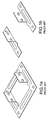
- Figs. 1a and 1b The most elementary known solutions, shown in Figs. 1a and 1b , involve simple flanges for attachment to a cabinet provided with orthogonal connecting tabs adapted to enable coupling with a cable-holder duct or tray member. These may take the form of full frames, in which case they are dedicated to a particular duct section ( Fig. 1a ), or may be formed by pairs of separate lateral members which can be adapted to duct sections of different width ( Fig. 1b ).
- a further drawback lies in the high number of articles that need to be available to allow for the connection of ducts of different sections (height, width).
- the company Tehalit uses a junction solution formed by a box-shaped body of prismatic shape, of modular type.
- the junction includes a pair of supports which may be applied to a wall or to the cabinet and are adapted to engage with a front cover panel, a pair of lateral closure caps and possibly a base cover.
- the cover panel has to be cut to size as a function of the width of the cabinet on which it is to be disposed, and the cable ducts are engaged on a surface of the panel at the location of openings obtained by cutting and removal of a portion of this surface.
- the cover panel comprises a series of pre-cut lines in positions corresponding to the possible heights of available ducts.
- this solution functions only in a wall support configuration of the duct and entails problems as regards the coupling between the duct and cabinet since no mechanical connection is provided, solely a closing up of the parts, making it impossible to ensure a high level of IP protection against external agents.
- the front cover panel is made from plastics material in order to provide an easier configuration by means of the removal of pre-cut sectors of its surface, a continuous electrical path cannot be ensured between conducting surfaces when metal ducts are being connected.
- the object of the present invention is to provide a universal solution for a junction between cable-trunkings and electrical cabinets which can be adapted to a range of ducts of different sections and allows for their fastening on any type of electrical cabinet.
- this object is achieved by means of a junction fitting having the characteristic features set out in claim 1.
- the present invention further relates to a kit for a junction fitting between a cable-trunking and an electrical cabinet, as claimed.
- the present invention is based on the principle of providing a modular junction fitting having a universal structure which includes a pair of lateral profiled sections in the form of uprights, provided with duct connection means, which may be connected together by means of a pair of closure panels, respectively a front panel and a base panel, and which forms, in its assembled configuration, a frustopyramidal box-shaped body open at top and bottom, whose cross-sectional area increases progressively from the duct connection section to the cabinet coupling section.
- a single version of the lateral profiled sections is provided, which is adapted to any type of duct among a plurality of available ducts of different height, and a universal panel module is provided which can be configured by an installer in order to achieve a front closure panel and a base closure panel which are both adapted to the height and possibly the width of the duct in question.
- this universal structure enables the assembly of a fitting for a junction between various types of duct (different in height and width, i.e. in section) and a cabinet, i.e. a junction fitting having a configuration adapted to one of a plurality of possible dimension classes of the cable-trunking and to the relative electrical cabinet for which it is intended.
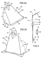
- a currently preferred embodiment of a universal structure for a junction fitting is shown in its elements in Figs. 2a, 2b and 3 , and in a partially assembled configuration in Figs. 4a to 4c .
- a pair of lateral upright profiled sections 10a, 10b is shown in a perspective view from different angles in Figs. 2a and 2b .
- They comprise a respective base wall 12a, 12b which is substantially vertical, a respective lateral wall 14a, 14b which is inclined and a respective front wall 16a, 16b which is also inclined; overall, they form a general frustopyramidal shape which extends between an upper section adapted to be connected to an end section of a cable duct and a second lower section adapted to be coupled to a wall of an electrical cabinet.
- the base wall is at right angles to the base sections via which coupling to the duct and the cabinet takes place, and ideally forms a prolongation of the base wall of the duct, as a result of which it is adapted to abut on a bearing support structure, such as a wall of the premises in which the ducting is laid, used to support the duct.
- the lateral and front walls are inclined with respect to the base sections as a result of which the cross-sectional area of each profiled section increases progressively from the duct connection section to the cabinet coupling section. The purpose of this is to offer a kind of inducement for the cables as regards access to the cabinet, thereby avoiding the drawback of small radii of curvature of the cables.
- the profiled sections 10a, 10b each have a plurality of duct connection tabs, extending at right angles to the upper duct connection section, shown respectively by 20a and 20b.
- there are three tabs enabling coupling with ducts of three different heights. Two of these tabs are provided with connection slots 22 and one is blind.
- the tabs are joined to a lateral wall of the profiled section via a weakened connection edge 24 or, as an alternative, via connection appendices which enable their selective removal.
- the profiled sections comprise, for each wall, a respective flange 26a, 26b each bearing a hole 28 for connection to a wall of the cabinet by means of known fastening means, for instance retaining screws.
- the front and base walls also comprise respective pairs of notches 32, 36 forming housings for the detachable connection of closure panels of the fitting.
- Fig. 3 is a lateral view of a universal closure panel module 40 of the fitting. It comprises two walls, respectively a base wall 40a and a lateral wall 40b, joined to form an obtuse or, in other variants, a right-angled dihedron. Transverse incisions 42', 42", 42'" are provided along the walls and at the connection edge and form lines weakening the panel in order to facilitate its breakage for configuring a front closure panel 50 and a base closure panel 52 as a function of the height of the duct to which the fitting is to be connected.
- the closure panels 50 and 52 may be obtained from a pair of universal modules 40, but, in an alternative variant, provision is made for a single common closure panel module 40, substantially similar to that shown in Fig. 3 , in which the lateral wall 40b is further prolonged in order to include a base panel portion from which the front panel portion is separated via a further transverse weakening incision.
- the lateral wall 40b further comprises hooking teeth formation 54, for instance (see the enlarged area), pairs of transverse ribs 56 projecting from the surface of the panel which define undercut portions 58 adapted to be received in a sliding or snap-locking manner and stably held by positive coupling between the pairs of notches 32, 36 of the front and base walls of the lateral profiled sections.
- This hooking solution assures that the closure panels 50, 52 can be removed to enable any cabling operation of the cabinet which may prove necessary after installation has taken place.
- Figs. 4a, 4b and 4c show the junction fitting of the invention in a partially assembled configuration, in which one of the two lateral profiled sections has been omitted solely to make the drawing clear, and coupled with three different types of cable duct whose heights differ (shown here without a cover).
- Fig. 4a shows the junction fitting in a coupled condition with a cable duct C1 of lower height, for instance a duct of a height of 50 mm provided with a single connection slot 60 in proximity of the end section of each lateral wall.
- the front closure panel 50 is formed by a first module 40 comprising the integral base wall 40a and the lateral wall 40b, and the base closure panel 52 is formed by a second module 40 configured by removal of the base wall and the upper section of the lateral wall along the incision line 42"'.
- Fig. 4b shows the junction fitting in a coupled condition with a cable duct C2 of medium height, for instance a duct of a height of 75 mm provided with two connection slots 60 aligned transversely in proximity of the end section of each lateral wall.
- the front closure panel 50 is formed by a first module 40 from which a portion is removed from the base wall 40a along the weakening line 42', and the base closure panel 52 is formed by a second module 40 configured by removal of the base wall and the upper section of the lateral wall along the incision line 42"'.
- Fig. 4c shows the junction fitting in a coupled condition with a cable duct C3 of greater height, for instance a duct of a height of 100 mm provided with three connection slots 60 in proximity of the end section of each lateral wall.
- the front closure panel 50 is formed by a first module 40 comprising only the integral lateral wall 40b, which may be obtained by removal of the base wall 40a along the weakening line 42", and the base closure panel 52 is formed by a second module 40 configured by removal of the base wall and the upper section of the lateral wall along the incision line 42"'.
- a dedicated fitting may be provided from a universal structure and the duct may be connected thereto via connection means which engage with the congruent slots such that the duct is always flush with the base wall of the fitting, enabling both components to abut on a bearing support structure, for instance a wall of the premises in which the ducting is laid.
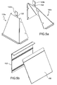
- Fig. 5a is a perspective view of a pair of lateral profiled sections 110a, 110b of a universal structure for a junction fitting according to a second embodiment of the invention
- Fig. 5b shows a front closure panel 150 and a base closure panel 152 adapted to be coupled to the lateral profiled sections 110a and 110b .
- lateral profiled sections 110a, 110b each comprise a single tab 120a, 120b provided with a slot 122.
- the front and base closure panels 150 and 152 may also be obtained from a universal (or common) closure panel module (not shown) which in this particular case comprises a base wall and a lateral wall forming the surfaces of a right-angled dihedron.
- Figs. 6a, 6b and 6c are perspective views of the junction fitting formed by the combination of the parts of Figs. 5a and 5b , fully or partially assembled, and coupled with a cable duct C of medium height (75 mm in the example) and with an electrical cabinet.
- the duct C may be disposed in a forward or a retracted position as a function of the arrangement of its connection slots 160 in order to obtain its superimposition with respect to the slots 122.
- Figs. 7a and 7b are perspective views from different angles of a junction fitting according to a third embodiment of the invention.
- the lateral profiled sections 210a, 210b comprise, in place of the tabs, a pair of opposing flange formations 220a and 220b of substantially triangular shape which extend in a direction orthogonal to the upper duct connection section and are provided with a plurality of longitudinally aligned connection slots 222 arranged to be engaged by duct connection means.
- Each flange formation also comprises a respective shaped surface portion 270a, 270b forming a groove facing the exterior of the profiled section, of a shape and extension corresponding to that of an edge portion of the duct shaped by drawing and adapted to receive a folded edge portion of a cover of the duct (not shown), so as to enable the engagement in a sliding or snap-locking manner of the edge of the duct on the pair of flanges 220a, 220b and its stable retention by positive coupling.
- the front closure panel 250 and the base closure panel 252 comprise, in addition to the transverse weakening incisions (not shown), possible longitudinal incisions, shown by reference numeral 280, which form weakening lines of the panel in order to facilitate its breakage with a view to its further configuration as a function of the width of the duct to which the fitting is to be connected.
- Figs. 8a, 8b and 8c are perspective views of the junction fitting, partially assembled, coupled with three different types of cable duct C1, C2 and C3 of different heights.
- the duct is keyed on the flanges and coupled thereto by sliding of its shaped edge portion with respect to the shaped surface portion 270a, 270b of the flanges.
- the duct is disposed on the flanges at a base section with variable depth as a function of the height of the duct, ensuring, in any case, that relative connection slots 222 and 260 are superimposed on one another.
- the closure panels 250 and 252 are thus configured as a function of the depth to which the duct is disposed on the flanges, by selective removal of portions along respective transverse weakening lines.
- the duct may be disposed in a forward or retracted position with respect to the base wall of the fitting, and therefore to a bearing support structure, for instance a wall of the premises in which the ducting is laid, as a function of its height.
- a further embodiment is possible, as shown in Figs. 9a and 9b , in which the flanges 320a and 320b have a plurality of parallel shaped surface portions 370a, 370b, each adapted to receive a shaped edge portion of the duct, as a function of its height.
- the lateral profiled sections are preferably made from metal material to ensure a solid and robust mechanical connection as well as electrical continuity with metal ducts.
- the front and base closure panels are preferably made from plastics material for greater ease of construction of the respective formations for connection to the profiled sections (by moulding) and to ensure a greater ease of configuration during cutting as well as flexibility of installation.
- duct connection flanges or tabs do not have a support function in any of the embodiments as the duct is generally supported by appropriate brackets.
- the solution as described makes it possible to obtain the same level of IP protection characteristic of the duct, without any deterioration.
- the fitting enables known cable gland devices to be secured on the cabinet.
Landscapes
- Engineering & Computer Science (AREA)
- Architecture (AREA)
- Civil Engineering (AREA)
- Structural Engineering (AREA)
- Casings For Electric Apparatus (AREA)
- Installation Of Indoor Wiring (AREA)
- Patch Boards (AREA)
Applications Claiming Priority (1)
| Application Number | Priority Date | Filing Date | Title |
|---|---|---|---|
| ITTO20070086 ITTO20070086A1 (it) | 2007-02-06 | 2007-02-06 | Accessorio di raccordo tra canali portacavi e quadri di comando |
Publications (2)
| Publication Number | Publication Date |
|---|---|
| EP1968166A2 true EP1968166A2 (de) | 2008-09-10 |
| EP1968166A3 EP1968166A3 (de) | 2011-04-20 |
Family
ID=39636964
Family Applications (1)
| Application Number | Title | Priority Date | Filing Date |
|---|---|---|---|
| EP08151056A Withdrawn EP1968166A3 (de) | 2007-02-06 | 2008-02-05 | Verbindungsstück zwischen Kabelkanälen und Schaltschränken |
Country Status (2)
| Country | Link |
|---|---|
| EP (1) | EP1968166A3 (de) |
| IT (1) | ITTO20070086A1 (de) |
Family Cites Families (1)
| Publication number | Priority date | Publication date | Assignee | Title |
|---|---|---|---|---|
| CH672563A5 (de) * | 1986-11-17 | 1989-11-30 | Ulrich Gantenbein |
-
2007
- 2007-02-06 IT ITTO20070086 patent/ITTO20070086A1/it unknown
-
2008
- 2008-02-05 EP EP08151056A patent/EP1968166A3/de not_active Withdrawn
Also Published As
| Publication number | Publication date |
|---|---|
| EP1968166A3 (de) | 2011-04-20 |
| ITTO20070086A1 (it) | 2008-08-07 |
Similar Documents
| Publication | Publication Date | Title |
|---|---|---|
| US20230034501A1 (en) | Interchangeable Modular Outlet Cover | |
| ES2754505T3 (es) | Grupo de construcción de suelo para un bastidor de un armario de distribución | |
| US8350154B1 (en) | Universal wall plate mount | |
| US9496689B2 (en) | Frame profile for a rack of a switchgear cabinet, and fastening clip for the frame profile | |
| WO2012101287A2 (en) | An assembly | |
| US5853098A (en) | Repositioning backplate for an electrical outlet box | |
| EP1968166A2 (de) | Verbindungsstück zwischen Kabelkanälen und Schaltschränken | |
| US20220372753A1 (en) | Folded ceiling baffle | |
| GB2467443A (en) | Cable tray bridge for joining trays or ducts | |
| US11646556B2 (en) | Raceway system | |
| US20130299208A1 (en) | Electrical Box With Convertible Component | |
| EP0399595A1 (de) | Mittels Verbindungsteilen zusammengebauter Schrank für elektrische Installationen | |
| DE102007006055B4 (de) | Schaltpult | |
| JP3180324U (ja) | 組立式個室 | |
| KR102684919B1 (ko) | 케이블덕트가 장착된 자동기계제어반 | |
| US20050056758A1 (en) | Base for a control box | |
| EP4117128A1 (de) | Konfigurierbares knick- oder abzweigungszubehör für ein kabelkanalsystem | |
| EP0198983B1 (de) | Paneel für eine Rasterdecke | |
| RU2485653C2 (ru) | Устройство для монтажа электрического блока в канале для прокладки электрических кабелей или проводов и электрический узел, содержащий электрический блок и такое устройство | |
| EP1420494B1 (de) | Elektrische Gerätadapter für oberflächige Einrichtungen | |
| FI86928C (fi) | Taeckplatta foer en kombination av eldosor | |
| EP3498129A1 (de) | Einrichtungsgegenstand mit integrierter kabelbaumanordnung | |
| EP1492974B1 (de) | Stützvorrichtung für technologisches system für wände | |
| US20250246889A1 (en) | Low voltage plate | |
| EP0860922B1 (de) | Kanalverbindung |
Legal Events
| Date | Code | Title | Description |
|---|---|---|---|
| PUAI | Public reference made under article 153(3) epc to a published international application that has entered the european phase |
Free format text: ORIGINAL CODE: 0009012 |
|
| AK | Designated contracting states |
Kind code of ref document: A2 Designated state(s): AT BE BG CH CY CZ DE DK EE ES FI FR GB GR HR HU IE IS IT LI LT LU LV MC MT NL NO PL PT RO SE SI SK TR |
|
| AX | Request for extension of the european patent |
Extension state: AL BA MK RS |
|
| PUAL | Search report despatched |
Free format text: ORIGINAL CODE: 0009013 |
|
| AK | Designated contracting states |
Kind code of ref document: A3 Designated state(s): AT BE BG CH CY CZ DE DK EE ES FI FR GB GR HR HU IE IS IT LI LT LU LV MC MT NL NO PL PT RO SE SI SK TR |
|
| AX | Request for extension of the european patent |
Extension state: AL BA MK RS |
|
| AKY | No designation fees paid | ||
| REG | Reference to a national code |
Ref country code: DE Ref legal event code: R108 |
|
| REG | Reference to a national code |
Ref country code: DE Ref legal event code: R108 Effective date: 20111228 |
|
| STAA | Information on the status of an ep patent application or granted ep patent |
Free format text: STATUS: THE APPLICATION IS DEEMED TO BE WITHDRAWN |
|
| 18D | Application deemed to be withdrawn |
Effective date: 20111021 |