EP1967759A1 - Safety device for joining and tightening filiform elements in general, including a high-strength mechanism which is guided along the entire course thereof - Google Patents
Safety device for joining and tightening filiform elements in general, including a high-strength mechanism which is guided along the entire course thereof Download PDFInfo
- Publication number
- EP1967759A1 EP1967759A1 EP06841744A EP06841744A EP1967759A1 EP 1967759 A1 EP1967759 A1 EP 1967759A1 EP 06841744 A EP06841744 A EP 06841744A EP 06841744 A EP06841744 A EP 06841744A EP 1967759 A1 EP1967759 A1 EP 1967759A1
- Authority
- EP
- European Patent Office
- Prior art keywords
- elements
- filiform
- general
- tensor
- inclined surface
- Prior art date
- Legal status (The legal status is an assumption and is not a legal conclusion. Google has not performed a legal analysis and makes no representation as to the accuracy of the status listed.)
- Granted
Links
Images


Classifications
-
- F—MECHANICAL ENGINEERING; LIGHTING; HEATING; WEAPONS; BLASTING
- F16—ENGINEERING ELEMENTS AND UNITS; GENERAL MEASURES FOR PRODUCING AND MAINTAINING EFFECTIVE FUNCTIONING OF MACHINES OR INSTALLATIONS; THERMAL INSULATION IN GENERAL
- F16G—BELTS, CABLES, OR ROPES, PREDOMINANTLY USED FOR DRIVING PURPOSES; CHAINS; FITTINGS PREDOMINANTLY USED THEREFOR
- F16G11/00—Means for fastening cables or ropes to one another or to other objects; Caps or sleeves for fixing on cables or ropes
- F16G11/10—Quick-acting fastenings; Clamps holding in one direction only
- F16G11/105—Clamps holding in one direction only
- F16G11/106—Clamps holding in one direction only using a toothed surface
-
- F—MECHANICAL ENGINEERING; LIGHTING; HEATING; WEAPONS; BLASTING
- F16—ENGINEERING ELEMENTS AND UNITS; GENERAL MEASURES FOR PRODUCING AND MAINTAINING EFFECTIVE FUNCTIONING OF MACHINES OR INSTALLATIONS; THERMAL INSULATION IN GENERAL
- F16G—BELTS, CABLES, OR ROPES, PREDOMINANTLY USED FOR DRIVING PURPOSES; CHAINS; FITTINGS PREDOMINANTLY USED THEREFOR
- F16G11/00—Means for fastening cables or ropes to one another or to other objects; Caps or sleeves for fixing on cables or ropes
- F16G11/04—Means for fastening cables or ropes to one another or to other objects; Caps or sleeves for fixing on cables or ropes with wedging action, e.g. friction clamps
-
- F—MECHANICAL ENGINEERING; LIGHTING; HEATING; WEAPONS; BLASTING
- F16—ENGINEERING ELEMENTS AND UNITS; GENERAL MEASURES FOR PRODUCING AND MAINTAINING EFFECTIVE FUNCTIONING OF MACHINES OR INSTALLATIONS; THERMAL INSULATION IN GENERAL
- F16G—BELTS, CABLES, OR ROPES, PREDOMINANTLY USED FOR DRIVING PURPOSES; CHAINS; FITTINGS PREDOMINANTLY USED THEREFOR
- F16G11/00—Means for fastening cables or ropes to one another or to other objects; Caps or sleeves for fixing on cables or ropes
- F16G11/10—Quick-acting fastenings; Clamps holding in one direction only
Definitions
- This invention has applications in the industry devoted to the manufacture of auxiliary elements for wire or filiform bodies tightening in general.
- This invention adds a new guiding component for the mobile elements of the blocking mechanism, which allows a smoother operation of said mechanism, avoiding any possibility of jamming; in this new configuration, mobile wedge elements push filiform elements away from each other, allowing a greater separation between them to facilitate their tightening; the wedge element of the blocking mechanism can incorporate any compound that allows achieving a greater hardness or resistance in these elements so as to allow their use with heavier loads.
- the tensor for filiform elements in general that is proposed by the invention is configured as an obvious novelty within its specific application field.
- the tensor for filiform elements in general is formed by a solid body and two covers, the assembly having two longitudinal through perforations, or channel-like holes, suited so as to receive two ends of a filiform element, wire, or any other element that is applied in a similar manner;
- the solid body is obtained directly by casting or injection molding and it has orifices for the incorporation of covers on the sides; the components that block the ends of the filiform element or wire are located inside the cavity of the body.
- These blocking components are formed by a mobile, wedge-like element that acts directly against the element to be blocked configured as the filiform body or wire, using a compression spring, and that allows the movement of the end of the filiform body or wire along one direction of the channel, but preventing this element to move in the opposite direction; the filiform element or wire being thus fixed to the body in a restricted and immovable way within the passing channel.
- the cover (5) has an extension (11) whose lower edge is parallel to the inclined surface (8) of the inner cavity (9) of the body (3), forming with this inclined surface a perfectly guided path throughout its length, with a wedge (6) and a spring (7) that pushes the wedge (6) directly over the surface of the cable, filiform element or wire (2), which will be retained with no possibility of movement at all on the direction opposite to that in which it is introduced; the wire goes through the channels (10) that are configured after the introduction of the cover (5) in the side hole or opening (9) of the body (3).
- the invention presents the application elements, such as the dented wheel (6) implemented with its support spring (7), located on the inclined surface (8) of the side opening (9) of the body (3), a cover (5) with an extension for the proper guidance of the dented wheel (6) throughout its path and which is introduced through one of the side openings (9) of the body (3) and remains inside it, the cable, wire, or filiform element being thus hanging inside it and immobilized by the action of the wedge (6) and the spring (7) that acts on it.
- the application elements such as the dented wheel (6) implemented with its support spring (7), located on the inclined surface (8) of the side opening (9) of the body (3), a cover (5) with an extension for the proper guidance of the dented wheel (6) throughout its path and which is introduced through one of the side openings (9) of the body (3) and remains inside it, the cable, wire, or filiform element being thus hanging inside it and immobilized by the action of the wedge (6) and the spring (7) that acts on it.
Landscapes
- Engineering & Computer Science (AREA)
- General Engineering & Computer Science (AREA)
- Mechanical Engineering (AREA)
- Details Of Connecting Devices For Male And Female Coupling (AREA)
- Installation Of Indoor Wiring (AREA)
- Invalid Beds And Related Equipment (AREA)
- Emergency Lowering Means (AREA)
Abstract
Description
- This descriptive summary refers to an Invention Patent application corresponding to a safety device to join and tighten filiform elements in general, in addition to its use for tightening wire lines, which is designed as a monoblock body.
- It is a system that can be used to connect and/or tighten wires or similar materials, guided with posts, fences, antennas, etc., and avoid that wires be twisted, bent by any means, or soldered.
- This invention has applications in the industry devoted to the manufacture of auxiliary elements for wire or filiform bodies tightening in general.
- The applicant is aware of the existence of tensors that can be used specially for tightening cables, wires, and filiform elements in general. This invention adds a new guiding component for the mobile elements of the blocking mechanism, which allows a smoother operation of said mechanism, avoiding any possibility of jamming; in this new configuration, mobile wedge elements push filiform elements away from each other, allowing a greater separation between them to facilitate their tightening; the wedge element of the blocking mechanism can incorporate any compound that allows achieving a greater hardness or resistance in these elements so as to allow their use with heavier loads.
- The tensor for filiform elements in general that is proposed by the invention is configured as an obvious novelty within its specific application field.
- Specifically, the tensor for filiform elements in general is formed by a solid body and two covers, the assembly having two longitudinal through perforations, or channel-like holes, suited so as to receive two ends of a filiform element, wire, or any other element that is applied in a similar manner; the solid body is obtained directly by casting or injection molding and it has orifices for the incorporation of covers on the sides; the components that block the ends of the filiform element or wire are located inside the cavity of the body.
- These blocking components are formed by a mobile, wedge-like element that acts directly against the element to be blocked configured as the filiform body or wire, using a compression spring, and that allows the movement of the end of the filiform body or wire along one direction of the channel, but preventing this element to move in the opposite direction; the filiform element or wire being thus fixed to the body in a restricted and immovable way within the passing channel.
- As a complement to the description herein included, and in order to help better understand the characteristics of the invention, two pages of descriptive but not limiting diagrams have been attached to this descriptive summary as an integral part of it, showing the following:
-
Figure 1 represents a perspective view of the assembly described by this invention, corresponding to a tensor for filiform elements in general, where the ends of the filiform element or wire that are joined and tightened within the object can be seen. -
Figure 2 represents a perspective view of the assembly described by this invention, corresponding to a tensor for filiform elements in general, with one of the covers introduced in the body and the other cover outside the body; the components that block the filiform element, composed of a spring and a dented roll as mobile wedge element, are also represented; the covers are located inside the body, which has orifices suited for their placement on the inside, this cavity also hosting the blocking components that form the retaining mechanism. -
Figure 3 represents a perspective view of the assembly described by this invention, corresponding to a tensor for filiform elements in general, where the side opening of the body for introducing the cover and the blocking components can be seen. -
Figure 4 , represents a section perspective view of the assembly described by this invention, corresponding to a tensor for filiform elements in general, where the covers and their corresponding blocking components that form the retaining mechanism, which will be added to the body, can be seen. -
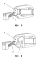
Figure 5 shows a front view of the invention represented in the previous figures fully mounted with its covers and the corresponding blocking components that form the retaining mechanism. -
Figure 6 shows a front view of the invention represented in the previous figures, with the ends of the cables or filiform elements to be joined. - These figures allow seeing how the tensor (1) of filiform elements in general (2) is formed by a body (3) that can present an orifice (4) in the center of its larger sides, has covers (5) that close the assembly and prevent the mechanisms that block filiform elements or wires to go out; these mechanisms are formed by a retaining element which in this case is a dented, wedge-like wheel (6) implemented by a spring (7); the dented wheel (6) rests on an inclined surface (8) of the inner cavity (9) of the body (3); this inclined surface forms an acute angle with the upper, adjacent side of the body cavity with respect to the inclined surface.
- The cover (5) has an extension (11) whose lower edge is parallel to the inclined surface (8) of the inner cavity (9) of the body (3), forming with this inclined surface a perfectly guided path throughout its length, with a wedge (6) and a spring (7) that pushes the wedge (6) directly over the surface of the cable, filiform element or wire (2), which will be retained with no possibility of movement at all on the direction opposite to that in which it is introduced; the wire goes through the channels (10) that are configured after the introduction of the cover (5) in the side hole or opening (9) of the body (3).
- The invention presents the application elements, such as the dented wheel (6) implemented with its support spring (7), located on the inclined surface (8) of the side opening (9) of the body (3), a cover (5) with an extension for the proper guidance of the dented wheel (6) throughout its path and which is introduced through one of the side openings (9) of the body (3) and remains inside it, the cable, wire, or filiform element being thus hanging inside it and immobilized by the action of the wedge (6) and the spring (7) that acts on it.
Claims (6)
- Connector and tensor of filiform elements in general that are devised to be used to join, fix, and tighten ends of filiform elements, wires or cables (2), which can be located between two rigid elements, such as posts, fences, etc., and that prevent wires or similar elements from being twisted, bent by any means or soldered, characterized for being composed of a monoblock body (3) with inner cavities (9) that have inclined surfaces (8) in the same general direction and one adjacent upper side forming an acute angle with respect to the inclined surface; inside these cavities the wire retaining mechanisms (6) and (7) and the covers (5) that close the assembly, are placed.
- Connector and tensor of filiform elements in general in accordance to claim 1 above, where the covers (5) close the assembly and prevent the mechanisms that retain the filiform element or wire from going out; these mechanisms are formed by a retaining element shaped like a wedge or dented wheel (6) that rests on the inclined surface (8) of the inner cavities (9) of the body (3), a spring (7) that rests on the inner hole of the cover (5) and that pushes the dented wheel (6) directly over the surface of the filiform element (2), which will be retained by wedging between the roller and the upper, adjacent side of the cavity (9), with no possibility of movement at all on the direction opposite to that in which it is introduced; the filiform element (2) goes through the channels (10) of the body (3); the configuration of these channels is completed after the introduction of the cover (5) in the side hole or opening (9) of the body (3).
- Connector and tensor of filiform elements in general in accordance to the previous claims, characterized because the dented roller (6) and the spring (7) are perfectly guided throughout their path by means of two long extensions (11) of the cover (5) so that, after their introduction inside the inner cavity (9) of the body (3), the lower border of these extensions runs parallel to the inclined surface (8) of the cavity (9) through the entire length of the cavity, which creates a path between the mentioned lower border of the extensions (11) and the inclined surface (8) that guides the dented wheel (6) and the spring (7) throughout their path, which prevents the displacement of the dented wheel and the spring outside their trajectory, throughout their path, thus facilitating the movement of the roller which follows reliably the inclined surface of the inner cavity (9), thus preventing possible roller jams.
- Connector and tensor of filiform elements in general in accordance to the previous claims, characterized because the mobile wedge elements (6) push filiform elements (2) in such a way that they tend to separate from each other, thus creating a greater space between them to facilitate their tightening.
- Connector and tensor of filiform elements in general in accordance to the previous claims, characterized because the wedge elements can be made of any material in accordance to the state of the art that provides them with high-resistance and hardness, including both metallic and ceramic materials that present such characteristics.
- Connector and tensor of filiform elements in general, in accordance to the previous claims, characterized because the geometry of the body (3) and the cover (5) can have different shapes so as to make both elements lighter, and be molded through casting or injection.
Applications Claiming Priority (2)
| Application Number | Priority Date | Filing Date | Title |
|---|---|---|---|
| ES200503120A ES2284365B2 (en) | 2005-12-20 | 2005-12-20 | SECURITY DEVICE TO JOIN AND TENSIFY FILIFORM ELEMENTS IN GENERAL, WITH HIGH RESISTANCE MECHANISM GUIDED THROUGHOUT THEIR TOUR. |
| PCT/ES2006/000692 WO2007071804A1 (en) | 2005-12-20 | 2006-12-18 | Safety device for joining and tightening filiform elements in general, including a high-strength mechanism which is guided along the entire course thereof |
Publications (3)
| Publication Number | Publication Date |
|---|---|
| EP1967759A1 true EP1967759A1 (en) | 2008-09-10 |
| EP1967759A4 EP1967759A4 (en) | 2010-08-25 |
| EP1967759B1 EP1967759B1 (en) | 2013-05-22 |
Family
ID=38188299
Family Applications (1)
| Application Number | Title | Priority Date | Filing Date |
|---|---|---|---|
| EP06841744.3A Active EP1967759B1 (en) | 2005-12-20 | 2006-12-18 | Safety device for joining and tightening filiform elements in general, including a high-strength mechanism which is guided along the entire course thereof |
Country Status (4)
| Country | Link |
|---|---|
| EP (1) | EP1967759B1 (en) |
| ES (1) | ES2284365B2 (en) |
| PT (1) | PT1967759E (en) |
| WO (1) | WO2007071804A1 (en) |
Cited By (6)
| Publication number | Priority date | Publication date | Assignee | Title |
|---|---|---|---|---|
| EP2213905A1 (en) * | 2009-01-28 | 2010-08-04 | Thomas & Betts International, Inc. | Cable gripping device |
| US8001660B2 (en) | 2007-10-31 | 2011-08-23 | Thomas & Betts International, Inc | Cable gripping device |
| EP2447569A3 (en) * | 2010-11-01 | 2012-12-05 | Thomas & Betts International, Inc. | Cable gripping device |
| WO2013116429A1 (en) * | 2012-02-03 | 2013-08-08 | E.J. Brooks Company | Tamper evident security seal |
| EP2687732A4 (en) * | 2011-03-15 | 2015-07-08 | Pracer Perfiladores S L L | Retention element for tensioned cables |
| US10913576B2 (en) | 2016-12-02 | 2021-02-09 | E.J. Brooks Company | Tamper evident locking device |
Families Citing this family (1)
| Publication number | Priority date | Publication date | Assignee | Title |
|---|---|---|---|---|
| ES2677104B1 (en) | 2016-12-28 | 2019-05-14 | Shiny Works S L | WIRE FINISHING DEVICE |
Family Cites Families (7)
| Publication number | Priority date | Publication date | Assignee | Title |
|---|---|---|---|---|
| US1139595A (en) * | 1914-02-24 | 1915-05-18 | Fred Starr | Clutch-clamp. |
| GB2210517B (en) * | 1987-09-26 | 1992-02-05 | Estate Wire Ltd | Connector for wires etc |
| IL113579A (en) * | 1994-05-05 | 1999-01-26 | Gripple Ltd | Connector for wires |
| JPH09151996A (en) * | 1995-11-29 | 1997-06-10 | Hitachi Metals Ltd | Fixture |
| GB2378213B (en) * | 2001-08-01 | 2004-01-14 | Gripple Ltd | Wire or like connectors/tensioners |
| US20030115723A1 (en) * | 2001-12-20 | 2003-06-26 | Shuey Alan B. | Releasable cable grip |
| ES1052858Y (en) * | 2002-09-20 | 2003-06-01 | Shiny Works S L | TERMINAL TENSIONER OF FILIFORM ELEMENTS IN GENERAL. |
-
2005
- 2005-12-20 ES ES200503120A patent/ES2284365B2/en not_active Expired - Fee Related
-
2006
- 2006-12-18 EP EP06841744.3A patent/EP1967759B1/en active Active
- 2006-12-18 PT PT68417443T patent/PT1967759E/en unknown
- 2006-12-18 WO PCT/ES2006/000692 patent/WO2007071804A1/en not_active Ceased
Cited By (12)
| Publication number | Priority date | Publication date | Assignee | Title |
|---|---|---|---|---|
| US8001660B2 (en) | 2007-10-31 | 2011-08-23 | Thomas & Betts International, Inc | Cable gripping device |
| US8578566B2 (en) | 2007-10-31 | 2013-11-12 | Thomas & Betts International, Inc. | Cable gripping device |
| EP2213905A1 (en) * | 2009-01-28 | 2010-08-04 | Thomas & Betts International, Inc. | Cable gripping device |
| EP2447569A3 (en) * | 2010-11-01 | 2012-12-05 | Thomas & Betts International, Inc. | Cable gripping device |
| EP2687732A4 (en) * | 2011-03-15 | 2015-07-08 | Pracer Perfiladores S L L | Retention element for tensioned cables |
| WO2013116429A1 (en) * | 2012-02-03 | 2013-08-08 | E.J. Brooks Company | Tamper evident security seal |
| GB2514279A (en) * | 2012-02-03 | 2014-11-19 | Brooks Co E J | Tamper evident security seal |
| CN104508323A (en) * | 2012-02-03 | 2015-04-08 | E.J.布鲁克斯公司 | Tamper evident security seal |
| US9558682B2 (en) | 2012-02-03 | 2017-01-31 | E.J. Brooks Company | Tamper evident security seal |
| CN104508323B (en) * | 2012-02-03 | 2017-03-08 | E.J.布鲁克斯公司 | Show the safety seal that seals off |
| GB2514279B (en) * | 2012-02-03 | 2018-05-23 | Brooks Co E J | Tamper evident security seal |
| US10913576B2 (en) | 2016-12-02 | 2021-02-09 | E.J. Brooks Company | Tamper evident locking device |
Also Published As
| Publication number | Publication date |
|---|---|
| PT1967759E (en) | 2013-08-28 |
| ES2284365A1 (en) | 2007-11-01 |
| EP1967759A4 (en) | 2010-08-25 |
| EP1967759B1 (en) | 2013-05-22 |
| WO2007071804A1 (en) | 2007-06-28 |
| ES2284365B2 (en) | 2008-09-16 |
Similar Documents
| Publication | Publication Date | Title |
|---|---|---|
| EP3129676B1 (en) | Improved gripping device | |
| US7603751B2 (en) | Displacement lock MLT | |
| US5147145A (en) | Connector for wires | |
| US7060893B1 (en) | Raceway construction for cables and pipes, including an antislipping cover | |
| US4313243A (en) | Sliding wedge cable clamp | |
| DE1942476A1 (en) | Self-locking cable strap | |
| EP1967759B1 (en) | Safety device for joining and tightening filiform elements in general, including a high-strength mechanism which is guided along the entire course thereof | |
| CN109219365B (en) | cord buckle | |
| EP3279116A1 (en) | Conveyor chain | |
| DE102015221450B4 (en) | Fastening device with a retaining bracket to which an equipment element can be temporarily fixed by means of a fixing device | |
| US6122804A (en) | Metal cable tie | |
| US9695908B2 (en) | Clamping assembly | |
| CZ47094A3 (en) | Feeding electric connector | |
| US828765A (en) | Rope-holder. | |
| EP1039632A2 (en) | Electric noise absorber and method of connection to a cable | |
| DE102006033800A1 (en) | Cable fastening device, has pair of opposite recesses provided in front side open cable groove for making cable connector to fasten cable that is inserted in groove, where groove has extension in axial direction over base | |
| JP4847760B2 (en) | Rope brake device | |
| CN111094080B (en) | Bolt with cover plate | |
| ITMI20131543A1 (en) | SNAP HOOK WITH CLIMBING LEVER | |
| DE1241174B (en) | Closure buckle | |
| WO2024157199A1 (en) | Clamping device with flexible exit barrier | |
| CN107387662B (en) | Holding device | |
| EP1255339B1 (en) | Boltless wedge clamp | |
| DE102004027902B4 (en) | Push contact for a battery connection has a contact pin for making contact with a counter contact, a flexible tightening element, a guiding device and a contact spring | |
| US7122749B2 (en) | Locking device |
Legal Events
| Date | Code | Title | Description |
|---|---|---|---|
| PUAI | Public reference made under article 153(3) epc to a published international application that has entered the european phase |
Free format text: ORIGINAL CODE: 0009012 |
|
| 17P | Request for examination filed |
Effective date: 20080618 |
|
| AK | Designated contracting states |
Kind code of ref document: A1 Designated state(s): AT BE BG CH CY CZ DE DK EE ES FI FR GB GR HU IE IS IT LI LT LU LV MC NL PL PT RO SE SI SK TR |
|
| A4 | Supplementary search report drawn up and despatched |
Effective date: 20100728 |
|
| PUAJ | Public notification under rule 129 epc |
Free format text: ORIGINAL CODE: 0009425 |
|
| 32PN | Public notification |
Free format text: COMMUNICATION PURSUANT TO RULE 70(2) AND 70A(2) EPC (EPO FORM 1224 DATED 10/09/2010) |
|
| RIC1 | Information provided on ipc code assigned before grant |
Ipc: F16G 11/10 20060101ALI20110706BHEP Ipc: F16G 11/04 20060101AFI20110706BHEP |
|
| 17Q | First examination report despatched |
Effective date: 20110809 |
|
| DAX | Request for extension of the european patent (deleted) | ||
| GRAP | Despatch of communication of intention to grant a patent |
Free format text: ORIGINAL CODE: EPIDOSNIGR1 |
|
| GRAS | Grant fee paid |
Free format text: ORIGINAL CODE: EPIDOSNIGR3 |
|
| GRAA | (expected) grant |
Free format text: ORIGINAL CODE: 0009210 |
|
| AK | Designated contracting states |
Kind code of ref document: B1 Designated state(s): AT BE BG CH CY CZ DE DK EE ES FI FR GB GR HU IE IS IT LI LT LU LV MC NL PL PT RO SE SI SK TR |
|
| REG | Reference to a national code |
Ref country code: GB Ref legal event code: FG4D |
|
| REG | Reference to a national code |
Ref country code: CH Ref legal event code: EP |
|
| REG | Reference to a national code |
Ref country code: AT Ref legal event code: REF Ref document number: 613398 Country of ref document: AT Kind code of ref document: T Effective date: 20130615 |
|
| REG | Reference to a national code |
Ref country code: IE Ref legal event code: FG4D |
|
| REG | Reference to a national code |
Ref country code: DE Ref legal event code: R096 Ref document number: 602006036504 Country of ref document: DE Effective date: 20130718 |
|
| REG | Reference to a national code |
Ref country code: PT Ref legal event code: SC4A Free format text: AVAILABILITY OF NATIONAL TRANSLATION Effective date: 20130819 |
|
| REG | Reference to a national code |
Ref country code: AT Ref legal event code: MK05 Ref document number: 613398 Country of ref document: AT Kind code of ref document: T Effective date: 20130522 |
|
| REG | Reference to a national code |
Ref country code: LT Ref legal event code: MG4D |
|
| PG25 | Lapsed in a contracting state [announced via postgrant information from national office to epo] |
Ref country code: GR Free format text: LAPSE BECAUSE OF FAILURE TO SUBMIT A TRANSLATION OF THE DESCRIPTION OR TO PAY THE FEE WITHIN THE PRESCRIBED TIME-LIMIT Effective date: 20130823 Ref country code: FI Free format text: LAPSE BECAUSE OF FAILURE TO SUBMIT A TRANSLATION OF THE DESCRIPTION OR TO PAY THE FEE WITHIN THE PRESCRIBED TIME-LIMIT Effective date: 20130522 Ref country code: SI Free format text: LAPSE BECAUSE OF FAILURE TO SUBMIT A TRANSLATION OF THE DESCRIPTION OR TO PAY THE FEE WITHIN THE PRESCRIBED TIME-LIMIT Effective date: 20130522 Ref country code: IS Free format text: LAPSE BECAUSE OF FAILURE TO SUBMIT A TRANSLATION OF THE DESCRIPTION OR TO PAY THE FEE WITHIN THE PRESCRIBED TIME-LIMIT Effective date: 20130922 Ref country code: LT Free format text: LAPSE BECAUSE OF FAILURE TO SUBMIT A TRANSLATION OF THE DESCRIPTION OR TO PAY THE FEE WITHIN THE PRESCRIBED TIME-LIMIT Effective date: 20130522 Ref country code: ES Free format text: LAPSE BECAUSE OF FAILURE TO SUBMIT A TRANSLATION OF THE DESCRIPTION OR TO PAY THE FEE WITHIN THE PRESCRIBED TIME-LIMIT Effective date: 20130902 Ref country code: AT Free format text: LAPSE BECAUSE OF FAILURE TO SUBMIT A TRANSLATION OF THE DESCRIPTION OR TO PAY THE FEE WITHIN THE PRESCRIBED TIME-LIMIT Effective date: 20130522 Ref country code: SE Free format text: LAPSE BECAUSE OF FAILURE TO SUBMIT A TRANSLATION OF THE DESCRIPTION OR TO PAY THE FEE WITHIN THE PRESCRIBED TIME-LIMIT Effective date: 20130522 |
|
| REG | Reference to a national code |
Ref country code: NL Ref legal event code: VDEP Effective date: 20130522 |
|
| PG25 | Lapsed in a contracting state [announced via postgrant information from national office to epo] |
Ref country code: BG Free format text: LAPSE BECAUSE OF FAILURE TO SUBMIT A TRANSLATION OF THE DESCRIPTION OR TO PAY THE FEE WITHIN THE PRESCRIBED TIME-LIMIT Effective date: 20130822 Ref country code: PL Free format text: LAPSE BECAUSE OF FAILURE TO SUBMIT A TRANSLATION OF THE DESCRIPTION OR TO PAY THE FEE WITHIN THE PRESCRIBED TIME-LIMIT Effective date: 20130522 |
|
| PG25 | Lapsed in a contracting state [announced via postgrant information from national office to epo] |
Ref country code: LV Free format text: LAPSE BECAUSE OF FAILURE TO SUBMIT A TRANSLATION OF THE DESCRIPTION OR TO PAY THE FEE WITHIN THE PRESCRIBED TIME-LIMIT Effective date: 20130522 |
|
| PG25 | Lapsed in a contracting state [announced via postgrant information from national office to epo] |
Ref country code: DK Free format text: LAPSE BECAUSE OF FAILURE TO SUBMIT A TRANSLATION OF THE DESCRIPTION OR TO PAY THE FEE WITHIN THE PRESCRIBED TIME-LIMIT Effective date: 20130522 Ref country code: SK Free format text: LAPSE BECAUSE OF FAILURE TO SUBMIT A TRANSLATION OF THE DESCRIPTION OR TO PAY THE FEE WITHIN THE PRESCRIBED TIME-LIMIT Effective date: 20130522 Ref country code: EE Free format text: LAPSE BECAUSE OF FAILURE TO SUBMIT A TRANSLATION OF THE DESCRIPTION OR TO PAY THE FEE WITHIN THE PRESCRIBED TIME-LIMIT Effective date: 20130522 Ref country code: BE Free format text: LAPSE BECAUSE OF FAILURE TO SUBMIT A TRANSLATION OF THE DESCRIPTION OR TO PAY THE FEE WITHIN THE PRESCRIBED TIME-LIMIT Effective date: 20130522 Ref country code: CZ Free format text: LAPSE BECAUSE OF FAILURE TO SUBMIT A TRANSLATION OF THE DESCRIPTION OR TO PAY THE FEE WITHIN THE PRESCRIBED TIME-LIMIT Effective date: 20130522 |
|
| PG25 | Lapsed in a contracting state [announced via postgrant information from national office to epo] |
Ref country code: NL Free format text: LAPSE BECAUSE OF FAILURE TO SUBMIT A TRANSLATION OF THE DESCRIPTION OR TO PAY THE FEE WITHIN THE PRESCRIBED TIME-LIMIT Effective date: 20130522 Ref country code: RO Free format text: LAPSE BECAUSE OF FAILURE TO SUBMIT A TRANSLATION OF THE DESCRIPTION OR TO PAY THE FEE WITHIN THE PRESCRIBED TIME-LIMIT Effective date: 20130522 |
|
| PLBE | No opposition filed within time limit |
Free format text: ORIGINAL CODE: 0009261 |
|
| STAA | Information on the status of an ep patent application or granted ep patent |
Free format text: STATUS: NO OPPOSITION FILED WITHIN TIME LIMIT |
|
| 26N | No opposition filed |
Effective date: 20140225 |
|
| REG | Reference to a national code |
Ref country code: DE Ref legal event code: R097 Ref document number: 602006036504 Country of ref document: DE Effective date: 20140225 |
|
| REG | Reference to a national code |
Ref country code: DE Ref legal event code: R119 Ref document number: 602006036504 Country of ref document: DE |
|
| REG | Reference to a national code |
Ref country code: CH Ref legal event code: PL |
|
| PG25 | Lapsed in a contracting state [announced via postgrant information from national office to epo] |
Ref country code: MC Free format text: LAPSE BECAUSE OF FAILURE TO SUBMIT A TRANSLATION OF THE DESCRIPTION OR TO PAY THE FEE WITHIN THE PRESCRIBED TIME-LIMIT Effective date: 20130522 Ref country code: LU Free format text: LAPSE BECAUSE OF FAILURE TO SUBMIT A TRANSLATION OF THE DESCRIPTION OR TO PAY THE FEE WITHIN THE PRESCRIBED TIME-LIMIT Effective date: 20131218 |
|
| REG | Reference to a national code |
Ref country code: IE Ref legal event code: MM4A |
|
| REG | Reference to a national code |
Ref country code: DE Ref legal event code: R119 Ref document number: 602006036504 Country of ref document: DE Effective date: 20140701 |
|
| PG25 | Lapsed in a contracting state [announced via postgrant information from national office to epo] |
Ref country code: IE Free format text: LAPSE BECAUSE OF NON-PAYMENT OF DUE FEES Effective date: 20131218 Ref country code: DE Free format text: LAPSE BECAUSE OF NON-PAYMENT OF DUE FEES Effective date: 20140701 Ref country code: CH Free format text: LAPSE BECAUSE OF NON-PAYMENT OF DUE FEES Effective date: 20131231 Ref country code: LI Free format text: LAPSE BECAUSE OF NON-PAYMENT OF DUE FEES Effective date: 20131231 |
|
| PG25 | Lapsed in a contracting state [announced via postgrant information from national office to epo] |
Ref country code: TR Free format text: LAPSE BECAUSE OF FAILURE TO SUBMIT A TRANSLATION OF THE DESCRIPTION OR TO PAY THE FEE WITHIN THE PRESCRIBED TIME-LIMIT Effective date: 20130522 Ref country code: CY Free format text: LAPSE BECAUSE OF FAILURE TO SUBMIT A TRANSLATION OF THE DESCRIPTION OR TO PAY THE FEE WITHIN THE PRESCRIBED TIME-LIMIT Effective date: 20130522 |
|
| PG25 | Lapsed in a contracting state [announced via postgrant information from national office to epo] |
Ref country code: HU Free format text: LAPSE BECAUSE OF FAILURE TO SUBMIT A TRANSLATION OF THE DESCRIPTION OR TO PAY THE FEE WITHIN THE PRESCRIBED TIME-LIMIT; INVALID AB INITIO Effective date: 20061218 |
|
| REG | Reference to a national code |
Ref country code: FR Ref legal event code: PLFP Year of fee payment: 11 |
|
| REG | Reference to a national code |
Ref country code: FR Ref legal event code: PLFP Year of fee payment: 12 |
|
| PGFP | Annual fee paid to national office [announced via postgrant information from national office to epo] |
Ref country code: PT Payment date: 20251124 Year of fee payment: 20 |
|
| PGFP | Annual fee paid to national office [announced via postgrant information from national office to epo] |
Ref country code: GB Payment date: 20251126 Year of fee payment: 20 |
|
| PGFP | Annual fee paid to national office [announced via postgrant information from national office to epo] |
Ref country code: IT Payment date: 20251125 Year of fee payment: 20 |
|
| PGFP | Annual fee paid to national office [announced via postgrant information from national office to epo] |
Ref country code: FR Payment date: 20251222 Year of fee payment: 20 |