EP1967751A2 - Dispositif de transmission destiné à la transmission d'un couple - Google Patents
Dispositif de transmission destiné à la transmission d'un couple Download PDFInfo
- Publication number
- EP1967751A2 EP1967751A2 EP08101754A EP08101754A EP1967751A2 EP 1967751 A2 EP1967751 A2 EP 1967751A2 EP 08101754 A EP08101754 A EP 08101754A EP 08101754 A EP08101754 A EP 08101754A EP 1967751 A2 EP1967751 A2 EP 1967751A2
- Authority
- EP
- European Patent Office
- Prior art keywords
- spindle nut
- transmission device
- spindle
- magnets
- shaft
- Prior art date
- Legal status (The legal status is an assumption and is not a legal conclusion. Google has not performed a legal analysis and makes no representation as to the accuracy of the status listed.)
- Granted
Links
Images


Classifications
-
- F—MECHANICAL ENGINEERING; LIGHTING; HEATING; WEAPONS; BLASTING
- F16—ENGINEERING ELEMENTS AND UNITS; GENERAL MEASURES FOR PRODUCING AND MAINTAINING EFFECTIVE FUNCTIONING OF MACHINES OR INSTALLATIONS; THERMAL INSULATION IN GENERAL
- F16D—COUPLINGS FOR TRANSMITTING ROTATION; CLUTCHES; BRAKES
- F16D43/00—Automatic clutches
- F16D43/02—Automatic clutches actuated entirely mechanically
- F16D43/26—Automatic clutches actuated entirely mechanically acting at definite angular position or disengaging after consecutive definite number of rotations
-
- F—MECHANICAL ENGINEERING; LIGHTING; HEATING; WEAPONS; BLASTING
- F16—ENGINEERING ELEMENTS AND UNITS; GENERAL MEASURES FOR PRODUCING AND MAINTAINING EFFECTIVE FUNCTIONING OF MACHINES OR INSTALLATIONS; THERMAL INSULATION IN GENERAL
- F16D—COUPLINGS FOR TRANSMITTING ROTATION; CLUTCHES; BRAKES
- F16D41/00—Freewheels or freewheel clutches
- F16D41/22—Freewheels or freewheel clutches with clutching ring or disc axially shifted as a result of lost motion between actuating members
-
- F—MECHANICAL ENGINEERING; LIGHTING; HEATING; WEAPONS; BLASTING
- F16—ENGINEERING ELEMENTS AND UNITS; GENERAL MEASURES FOR PRODUCING AND MAINTAINING EFFECTIVE FUNCTIONING OF MACHINES OR INSTALLATIONS; THERMAL INSULATION IN GENERAL
- F16D—COUPLINGS FOR TRANSMITTING ROTATION; CLUTCHES; BRAKES
- F16D2300/00—Special features for couplings or clutches
- F16D2300/18—Sensors; Details or arrangements thereof
Definitions
- the present invention relates to a mechanical transmission device for the elastic transmission of a torque.
- a transmission device In order to transfer a torque or a load from a drive shaft to an output shaft, a transmission device, such as e.g. used a clutch.
- a transmission device such as e.g. used a clutch.
- the transmitting elements are made of metal (e.g., spring steel), rubber, or other linear elastic members, such as rubber. pneumatic cylinders or the like.
- electromechanical actuators with a soft-start function are known in which a gradual increase in the transmitted torque to the output shaft is achieved by means of a specific current or voltage profile, which is applied to the exciting motor.
- this has the disadvantage of higher production and operating costs due to the additional necessary controls.
- electrical control is susceptible to interference and in certain environments (for example, due to lack of electromagnetic compatibility) not desirable.
- the idea underlying the invention is to make the interaction between the spindle nut and damping device so that a change of torque on the drive shaft is first converted into a translational movement of the spindle nut on the spindle shaft section, which with increasing attenuation of the translational movement gradually a change in the torque of the output shaft pulls.
- an elastic transmission of torque is realized with definable game.
- the elastic transmission of torques and thus a soft-start with gradual load transfer achieved solely by mechanical means, so that no complex electrical control is necessary.
- the individual elements eg field strength of Magnet, thread pitch of the spindle, length of the spindle shaft section, etc.
- drive shaft and "output shaft” are merely illustrative, but the power flow within the device is not limited to one direction.
- the device according to the invention can be bidirectional; Thus, operating states and types may also be present in which a force or a torque is transmitted from the output shaft to the drive shaft.
- the damping device has at least two magnets which are each arranged at one end of the spindle shaft section.
- the magnets may be formed, for example, as a ring magnet, which are arranged coaxially to the spindle shaft portion.
- the magnets may for example be designed as electromagnets.
- the game or the hysteresis of the device can be set dynamically and adapted to the current operating conditions.
- the magnets may also be designed as permanent magnets, for example as neodymium magnets or samarium-cobalt magnets.
- the spindle nut has two ring magnets, which are each arranged opposite the coaxial with the spindle shaft portion magnets, wherein like poles of the ring magnet of the spindle nut and the magnets of the damping device are arranged opposite each other, so that the spindle nut is held in the unloaded state in the middle of the spindle shaft section.
- a stop may be provided in each case, which limits the translational movement of the spindle nut.
- the damping device has two spiral springs, which are each arranged between the spindle nut and the ends of the spindle shaft section.
- the damping device has two rubber elements, which are each arranged between the spindle nut and the ends of the spindle shaft section. These two rubber elements may be toroidal and coaxially disposed about the spindle shaft portion.
- the spindle nut is typically translationally movable in relation to the output element.
- a transmission device can be realized in which the drive shaft and the output shaft are not translational but only rotationally movable relative to each other.
- the output element has a cylinder sleeve which is rotatably coupled to the spindle nut and is rigidly connected to the output shaft.
- the spindle nut may be connected to the cylinder sleeve, for example by means of a splined connection.
- the spindle nut rotatably but translatorily movable coupled to the output shaft.
- the spindle nut is rigidly connected to the output member.
- a transmission device can be realized in which the output shaft is moved in a change of the transmitted torque together with the spindle nut in the axial direction.
- the drive shaft and the output shaft are arranged on different axes of rotation.
- a transmission device can be realized, which can be flexibly integrated into existing drive solutions.
- the drive shaft can be mounted for example via ball bearings in the damping device or in the attacks.
- two Hall sensors are provided, which are arranged along and outside the spindle shaft portion, and which each output a position signal, which depends on the position of the spindle nut.
- a torque sensor By additionally providing an evaluation device, which generates a torque signal based on the position signals output by the Hall sensors, which depends on the transmitted torque, a torque sensor can furthermore be realized. It is exploited that the position of the spindle nut on the spindle shaft portion depends on the transmitted torque.
- FIGS. 1 and 2 the structure of a transmission device according to the invention for transmitting a torque described.
- FIG. 1 is a schematic sectional view of an exemplary arrangement of such a transfer device.
- a drive shaft 1 has a spindle shaft section 4, on which a spindle nut 5 is translationally movable.
- the translational movement of the spindle nut 5 is limited by two stops 2 and 7, which are arranged at the two ends of the spindle shaft portion 4.
- the spindle shaft portion 4 may be formed as a screw and the spindle nut 5 have on its inner circumference a corresponding thread, so that a rotational movement of the drive shaft 1 can first be converted into a translational movement of the spindle nut 5.
- the spindle shaft portion 4, the spindle nut 5 and the two stops 2 and 7 are surrounded by a cylinder sleeve 9, the rotatably connected to an output shaft 10 is connected.
- the cylinder sleeve 9 and the output shaft 10 together form an output element.
- the stops 2 and 7 are each mounted with a ball bearing 11 in the cylinder sleeve 9.
- the spindle nut 5 is rotatably coupled via its outer circumference with the cylinder sleeve 9, while it is arranged to be translationally movable on the spindle shaft section 4.
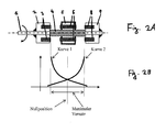
- Fig. 2A shows a part of the arrangement in Fig. 1 , in particular the drive shaft 1 and the spindle nut 5 arranged thereon, and the stops 2 and 7 arranged laterally to the spindle nut 5.
- the ring magnets 3, 6 and 8 are each magnetized in the axial direction.
- the poles of the ring magnet 6 of the spindle nut 5 are each arranged opposite to similar poles of the ring magnets 3 and 8 of the stops 2 and 7.
- the order of the poles of the ring magnet in stop 2, spindle nut 5 and stop 7 is thus for example NS SN NS or SN NS SN.
- the spindle nut 5 has only one ring magnet 6, but may also be provided with two ring magnets.
- Fig. 3A schematically shows the rotational speed (angular velocity) of the drive shaft 1 in an exemplary start-up operation.
- Fig. 3B shows the rotational speed (angular velocity) of the output shaft 10 in this startup process.
- the drive shaft 1 and the output shaft 10 are at rest and the spindle nut 5 is in the zero position.
- This condition corresponds to phase A (in Fig. 3B ).
- the spindle nut 5 on the spindle shaft portion 4 translationally (for example, to the right) moves.
- the spindle nut 5 and consequently the rotationally coupled output shaft 10 do not yet rotate.
- the spindle nut 5 moves translationally relative to the surrounding cylindrical sleeve 9.
- This phase B corresponds to a delay and thus thus a characteristic of the transmission game.
- phase D a stationary state is reached, in which the force acting on the spindle nut 5 spring force of the ring magnet is in equilibrium with the propelling force of the spindle shaft.
- the spindle nut 5 is in this state so not in the zero position but at a torque-dependent position between the zero position and one of the stops 2 and 7. Furthermore, in this state, the spindle nut 5 transmits the entire torque from the drive shaft 1 to the rotationally with the spindle nut 5 coupled output shaft 10th
- Fig. 4 shows the rotation angle of the drive shaft 1 (curve 3) and the output shaft 10 (curve 4) in a typical start-up operation.
- the spring action of the ring magnet is particularly clear. After a quick turn of the drive shaft 1, this is braked to a standstill and slightly springs back (local maximum in curve 3), while the output shaft 10 starts gently.
- phase D If, in the stationary state (phase D), the drive shaft 1 brakes abruptly or the sense of rotation of the drive shaft 1 jerkily reversed, then the output shaft 10 follows this torque change with delay and in a damped by the spring action. Thus, a hysteresis-transmitted transmission of the torque from the drive shaft 1 to the output shaft 10 is achieved.
- the ring magnets may be formed, for example, as permanent magnets, e.g. as neodymium magnets or samarium cobalt magnets.
- the ring magnets 3 and 8 it is also possible, in particular for the ring magnets 3 and 8 to use electromagnets which are controlled by a control device (not shown in detail). The strength of the magnetic field is thus externally controllable. This has the advantage that the game or the hysteresis can be adjusted dynamically and adapted to the operating conditions.
- the two magnets 3 and 8 can also be set to different strengths, whereby certain hysteresis profiles can be realized and for a direction of rotation a lesser game than for the other can be set. In addition, oscillations can be avoided by the dynamic control of the electromagnet.
- magnets have been cited as examples of a damping device, but it is also possible to use rubber elements, coil springs or other spring elements instead of magnets as a damping device, as illustrated by the following examples.
- Fig. 5 shows a perspective sectional view of a first specific embodiment of the arrangement schematically described above.
- the spindle nut 5 is movably disposed on the spindle shaft portion 4 of the drive shaft 1.
- a ring magnet 6 is provided in each case.
- the drive shaft 1 is mounted with ball bearings 11 in a housing which comprises the cylinder sleeve 9 and a cover flange 13 attached thereto.
- the drive-side ball bearing 11 is fastened to a bearing receptacle 14 in the cover flange.
- the output-side ball bearing 11 is fastened with a bearing receptacle 15 in the cylinder sleeve 9.
- the stopper 2 In the drive-side end of the cylinder sleeve 9, the stopper 2 is provided, which serves as a magnetic receptacle for the ring magnet 3 arranged therein.
- the stop 7 In the output side end of the cylinder sleeve, the stop 7 is provided, which serves as a magnetic receptacle for the ring magnet 8 arranged therein.
- Fig. 5 are north and south pole of the ring magnets 3, 6 and 8 indicated by a division of the magnets. In fact, however, the ring magnets 3, 6 and 8 are integrally formed and north and south pole are not visible from the outside.
- the spindle nut 5 On the inner circumference of the cylinder sleeve 9, wedge elements 16 are preferably formed, which engage in corresponding wedge elements 17 on the outer circumference of the spindle nut 5.
- the spindle nut 5 is translationally movable and at the same time rotatably engaged with the cylinder sleeve 9. It is thus realized a simple linear guide of the spindle nut 5 by means of planar surfaces.
- the cylinder sleeve 9 is rotatably connected to the output shaft 10 and, as in in Fig. 5 illustrated example, be integrally formed with her.
- an elastic coupling is provided which enables a hysteresis-based transmission of torques.
- the game provided by fixed selection of the above parameters is permanently definable.
- this embodiment is the simple integration into existing drive trains due to the identical axis of rotation of drive shaft 1 and output shaft 10. Furthermore, this embodiment has a compact design.
- Fig. 6 shows a perspective sectional view of a second concrete embodiment of the arrangement schematically described above.
- Fig. 6 are the same or functionally identical elements as in Fig. 1 and 5 denoted by the same reference numerals and will not be explained in detail. The explanations of these elements in relation to Fig. 1 and 5 apply analogously for the in Fig. 6 shown elements.
- the spindle nut 5 is not translationally movable relative to the output shaft 10, but is also connected translationally fixed thereto.
- the spindle nut 5 is fixedly connected to a connecting flange 19 by a plurality of (for example three) guide rods 18, which flange is flanged to the output shaft 10 in a rotationally fixed manner.
- the spindle nut 5 is rigid with one end of the guide rods 18 and the connecting flange 19 is rigidly connected to the other end of the guide rods 18.
- the spindle nut 5 is rotatably mounted in the cylinder sleeve 9 by means of a sliding bearing.
- the cylinder sleeve 9 On the side facing the drive shaft 1, the cylinder sleeve 9 has a cylinder bottom, in which a recess is provided into which the bearing receptacle 15 is fitted. In the bearing seat 15, the ball bearing 11 is received.
- On the output shaft 10 side facing the cylinder sleeve 9 is completed with a Abdeckflansch 13 which is rotatably mounted in the cylinder sleeve 9 by means of a sliding bearing.
- the cover flange 13 has a plurality of through holes 13a, 13b, through which the guide rods 18 are passed.
- the cover flange 13 is mounted in the cylinder sleeve 9 in such a way that it is rotatable in the cylinder sleeve 9, but not translationally movable.
- the torque is transmitted from the spindle nut 5 via the guide rods 18 on the cover 13.
- the cover flange 13 thus always rotates at the same angular speed as the spindle nut 5, the spindle nut 5 being translationally movable in relation to the cover flange 13.
- the connecting flange 19 transmits both the translational and the rotational movement of the spindle nut 5 to the output shaft 10.
- the output shaft 10 is thus moved in a change of the torque of the drive shaft 1 together with the spindle nut 5 in the axial direction, wherein the length this axial displacement depends on the transmitted torque.
- Other aspects of the present embodiment, particularly the hysteresis behavior at start-up and stop, are substantially as described in the first embodiment.
- This configuration allows in particular to achieve a torque-dependent axial displacement of the output shaft. Moreover, this embodiment also achieves the effects of the first embodiment, e.g. the ability to provide a flexible coupling with adjustable play and hysteresis.
- Fig. 7 shows a perspective sectional view of a third specific embodiment of the arrangement described above schematically.
- Fig. 7 are the same or functionally identical elements as in Fig. 1 . 5 and 6 denoted by the same reference numerals and will not be explained in detail. The explanations of these elements in relation to Fig. 1 . 5 and 6 apply analogously for the in Fig. 7 shown elements.
- the torque from the spindle nut 5 is given to the output shaft 10 via the guide rods 18 guided through the cover flange 13 and the connection flange 19.
- the guide rods are not fixedly connected to the connecting flange 19 in this third embodiment, but (for example, with a linear sliding bearing) are slidably mounted in the connecting flange 19, so that the translational movement of the spindle nut 5 is not passed to the connection flange 19 and the output shaft 10.
- the guide rods 18 are designed substantially longer than in the second embodiment and extend when the spindle nut 5 is arranged in the zero position beyond the connecting flange 19 to a translational movement of the spindle nut 5 in both directions from the zero position enable.
- this embodiment is the same as that of the first embodiment, and the aforementioned effects of the first embodiment are also achieved here.
- this third embodiment is more expensive to manufacture than the first embodiment, since a plurality of parallel surfaces must be generated, but it can be designed without play by adjusting the bearings and biasing the spindle nut. In contrast, it is achieved over the first embodiment that the number of Friction points is lower than in the third embodiment, and there are fewer load cases that can lead to jamming.
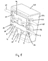
- Fig. 8 shows a perspective sectional view of a fourth specific embodiment of the arrangement described above schematically.
- Fig. 8 are the same or functionally identical elements as in Fig. 1 and 5 denoted by the same reference numerals and will not be explained in detail. The explanations of these elements in relation to Fig. 1 and 5 apply analogously for the in Fig. 8 shown elements.
- the fourth embodiment in Fig. 8 Characterized mainly by the fact that the drive shaft 1 and the output shaft 10 are not arranged coaxially to each other, but on different axes of rotation.
- the drive shaft 1 and the output shaft 10 are mounted with ball bearings 11 and 21 in a housing 22.
- the housing is closed with a housing cover 23.
- the drive shaft 1 is merely led out of the one housing side, whereas the output shaft 10 is led out of both sides of the housing. This leads to the fact that the rotational power can be used on the output side on both sides of the housing or by two gear trains.
- the drive shaft 1 and the output shaft 10 are arranged parallel to each other.
- the output shaft 10 has a gear formed as a wide gear portion 24 and that substantially with a length corresponding to the spindle shaft portion 4.
- the spindle nut 5 is in this case not provided with wedge elements 17 as in the first embodiment, but with a toothing 25 (shown here only schematically) and thus designed as a spur gear.
- a toothing 25 shown here only schematically
- power transmission by means of wedge elements is also possible.
- the toothing 25 of the spindle nut 5 engages in the teeth of the gear portion 24 and thus transmits a torque from the spindle nut 5 to the output shaft 10. Again, so are the spindle nut 5 and the output shaft 10 rotationally engaged with each other.
- the spindle nut 5 is translational movable to the output shaft 10.
- the ring magnets 3 and 8 are mounted on the bearing receivers 14 and 15, and serve in this embodiment as stops.
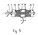
- Fig. 9 shows a schematic sectional view of part of a fifth embodiment of the arrangement schematically described above.
- the representation in Fig. 9 corresponds to the illustration in Fig. 2 and shows the fifth embodiment without the cylinder sleeve and thus fixedly connected output shaft.
- Fig. 9 are the same or functionally identical elements as in Fig. 1 and 2 denoted by the same reference numerals and will not be explained in detail. The explanations of these elements in relation to Fig. 1 and 2 apply analogously for the in Fig. 9 shown elements.
- the fifth embodiment differs from the previously described embodiments mainly in that as damping elements two coil springs 30, 31 are provided, which are arranged on the two sides of the spindle nut 5 or spindle shaft section 4 about the drive shaft 1 and the spindle shaft section 4.
- the coil spring 30 is connected at its one end to the stopper 2 and connected at its other end to one side of a thrust bearing 32, which may be formed, for example, as an axial ball bearing or the like.
- the other side of the thrust bearing 32 is fixedly connected to the spindle nut 5.
- the coil spring 31 is connected at one end to the stopper 7 and at the other End connected to one side of a thrust bearing 33.
- the other side of the thrust bearing 33 is fixedly connected to the spindle nut 5.
- the spindle nut 5 acts from each of the two coil springs 30 and 31, a spring force on the spindle nut 5, which cancel these two spring forces in the zero position. If the spindle nut 5 is deflected from the zero position, then one of the coil springs is further compressed while the other approaches its relaxed state, so that a total of a spring force acts on the spindle nut 5 in the direction of the zero position.
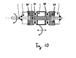
- Fig. 10 shows a schematic sectional view of a portion of a sixth embodiment of the arrangement schematically described above.
- the representation in Fig. 10 corresponds to the illustration in Fig. 2 and shows the sixth embodiment without the cylinder sleeve and thus fixedly connected output shaft.
- Fig. 10 are the same or functionally identical elements as in Fig. 1 and 2 denoted by the same reference numerals and are not explained in detail. The explanations of these elements in relation to Fig. 1 and 2 apply analogously for the in Fig. 10 shown elements.
- the sixth embodiment differs from the embodiments described so far mainly in that there are provided as damping elements, two donut-shaped rubber elements 35, 36 which are arranged on the two sides of the spindle nut 5 about the spindle shaft section 4.
- the rubber element 35 is attached at its one end to the stopper 2 and connected at its other end to one side of a thrust bearing 37, which may be formed, for example, as an axial ball bearing or the like.
- the other side of the thrust bearing 37 is fixedly connected to the spindle nut 5.
- the rubber member 35 is attached at its one end to the stopper 7 and connected at its other end to one side of a thrust bearing 38.
- the other side of the thrust bearing 38 is fixedly connected to the spindle nut 5.
- the rubber elements 35, 36 are elastically deformable and exert spring forces on the spindle nut 5 (similar to the coil springs of the fifth embodiment).
- the operation of this embodiment corresponds to that described for the first embodiment, with the difference that the forces acting on the spindle nut 5 damping forces are provided here by the rubber elements 35 and 36.
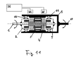
- Fig. 11 shows a schematic sectional view of a seventh embodiment of the present invention.
- two Hall sensors 25 are arranged along the cylinder sleeve 9, which are connected on the output side to an evaluation circuit 26. Other Aspects of this embodiment are as described for example for the first embodiment.
- the two Hall sensors 25 are each arranged centrally between the zero position and the stops 2 and 7 respectively.
- the cylinder sleeve 9 is made of a non-ferromagnetic material, e.g. Brass or plastic. For this reason, the magnetic flux emanating from the magnets 3, 6 and 8 can penetrate the cylinder sleeve 9 and reach the Hall sensors 25.
- the magnetic flux emitted by the magnets 3, 6 and 8 depends on the position of the spindle nut 5 on the spindle shaft section 4.
- the Hall sensors 25 each generate an output signal which depends on the magnetic field and thus on the position of the spindle nut 5.
- the evaluation unit 26 compares these two output signals and in turn generates a signal indicating the position of the spindle nut 5.
- this arrangement can thus be used advantageously as a torque sensor.
- the information thus obtained about the position of the spindle nut 5 can also be used to control the arrangement.
- a control device controllable electromagnets for the magnets 3 and 8 in the stops 2 and 7 respectively can be used by means of a control device controllable electromagnets for the magnets 3 and 8 in the stops 2 and 7 respectively.
- a control can be set up which detects the position of the spindle nut 5 and its change by means of the Hall sensors 25 and the evaluation device 26.
- the strength of the magnetic field of the electromagnets can then be controlled, for example, as a function of the position of the spindle nut 5 and / or the change in this position.
- defined hysteresis curves as well as playing characteristics can be achieved, or also to avoid oscillations. It is also possible to determine the position of the spindle nut 5 with only one Hall sensor 25.
- the spindle nut and the output shaft can also be coupled to one another via a magnetic bearing.
- Such a configuration has the advantage that the resulting frictional forces are very low.
- the transmission device according to the invention can advantageously be integrated into a series of kinematic systems.
- a drive element for example a motor
- a load to be driven to the output shaft.
- the transmission device can be advantageously integrated in transmissions (for example in planetary gears), whereby the elastic properties (play, hysteresis) can be adapted to the transmission parameters. It can be exploited that many gearboxes have an open architecture based on the modular principle.
- the transmission device according to the invention can avoid mechanical stresses at standstill.
- the elements of the kinematic chain are subject to structural stresses after the excitation is set to zero.
- these (residual) voltages can not only be reduced but completely eliminated.
- electromechanical actuators the spindle nut can be moved back to the zero position, resulting in a discharge and Lifting the tension leads.
- a voltage reduction is made possible by a non-self-locking spindle.
- Another field of application are bidirectional actuators in which the drive shaft and the output shaft can be exchanged or reversed.
- An example of this is an actuator to open a door.
- a motor can be provided on one side (for example on the drive shaft), but the door can also be moved manually in the other direction.
- elasticity and hysteresis properties are required, which can be provided by the present transmission device.
Landscapes
- Engineering & Computer Science (AREA)
- General Engineering & Computer Science (AREA)
- Mechanical Engineering (AREA)
- Transmission Devices (AREA)
- Manipulator (AREA)
- Power Steering Mechanism (AREA)
- Eye Examination Apparatus (AREA)
Applications Claiming Priority (1)
| Application Number | Priority Date | Filing Date | Title |
|---|---|---|---|
| DE102007008492A DE102007008492A1 (de) | 2007-02-21 | 2007-02-21 | Übertragungsvorrichtung zur Übertragung eines Drehmoments |
Publications (3)
| Publication Number | Publication Date |
|---|---|
| EP1967751A2 true EP1967751A2 (fr) | 2008-09-10 |
| EP1967751A3 EP1967751A3 (fr) | 2008-10-01 |
| EP1967751B1 EP1967751B1 (fr) | 2009-10-28 |
Family
ID=39637709
Family Applications (1)
| Application Number | Title | Priority Date | Filing Date |
|---|---|---|---|
| EP08101754A Not-in-force EP1967751B1 (fr) | 2007-02-21 | 2008-02-19 | Dispositif de transmission destiné à la transmission d'un couple |
Country Status (3)
| Country | Link |
|---|---|
| EP (1) | EP1967751B1 (fr) |
| AT (1) | ATE447118T1 (fr) |
| DE (2) | DE102007008492A1 (fr) |
Cited By (3)
| Publication number | Priority date | Publication date | Assignee | Title |
|---|---|---|---|---|
| CN102345687A (zh) * | 2010-07-22 | 2012-02-08 | 杨泰和 | 通过初始限转矩滑动阻尼致动的离合器 |
| CN105156505A (zh) * | 2015-09-28 | 2015-12-16 | 中国矿业大学 | 一种小型滑块式低速离合器 |
| CN109404504A (zh) * | 2017-08-17 | 2019-03-01 | 罗伯特·博世有限公司 | 具有平行布置和连接的丝杠的线性运动装置 |
Families Citing this family (2)
| Publication number | Priority date | Publication date | Assignee | Title |
|---|---|---|---|---|
| DE102011010153B4 (de) * | 2011-02-02 | 2012-11-08 | Voith Patent Gmbh | Hydrodynamische Komponente |
| DE102018213445A1 (de) * | 2018-08-09 | 2020-02-13 | Lucas Automotive Gmbh | Fahrzeugeinrichtung mit einer Spindel/Mutter-Anordnung und mit einer Verdrehsicherung sowie Verfahren zum Montieren einer Verdrehsicherung für ein Herstellen einer solchen Fahrzeugeinrichtung |
Family Cites Families (8)
| Publication number | Priority date | Publication date | Assignee | Title |
|---|---|---|---|---|
| GB136275A (en) * | 1918-12-14 | 1919-12-15 | Samuel Griffin | Automatic Adjustment of Friction Clutches. |
| GB430967A (en) * | 1934-12-27 | 1935-06-27 | Edward Vincer Haslam | Torque thrust power transmission |
| US4143747A (en) * | 1977-09-02 | 1979-03-13 | Langieri Jr Michael | Coaster brake |
| DE4019482A1 (de) * | 1990-06-19 | 1992-01-09 | Diehl Gmbh & Co | Ruderstelleinrichtung |
| ES2112706B1 (es) * | 1994-05-06 | 1998-10-16 | Centralair Sa | Actuador integral. |
| DE29521602U1 (de) * | 1995-06-03 | 1997-10-16 | Beikirch Industrieelektronik GmbH, 32429 Minden | Elektrischer Schub-Zug-Spindelantrieb |
| FR2757585B1 (fr) * | 1996-12-19 | 1999-03-19 | Waligora Julien | Limiteur mecanique de force pour verin electrique lineaire a vis |
| DE10102685B4 (de) * | 2001-01-22 | 2004-04-08 | Fico Cables, S.A., Rubi | Betätigungsmechanismus mit Kraftsensor für eine Bremse |
-
2007
- 2007-02-21 DE DE102007008492A patent/DE102007008492A1/de not_active Withdrawn
-
2008
- 2008-02-19 DE DE502008000158T patent/DE502008000158D1/de active Active
- 2008-02-19 EP EP08101754A patent/EP1967751B1/fr not_active Not-in-force
- 2008-02-19 AT AT08101754T patent/ATE447118T1/de active
Cited By (5)
| Publication number | Priority date | Publication date | Assignee | Title |
|---|---|---|---|---|
| CN102345687A (zh) * | 2010-07-22 | 2012-02-08 | 杨泰和 | 通过初始限转矩滑动阻尼致动的离合器 |
| EP2410194A3 (fr) * | 2010-07-22 | 2012-07-04 | Tai-Her Yang | Embrayage actionné par un amortissement coulissant limiteur de couple initial |
| CN102345687B (zh) * | 2010-07-22 | 2016-06-15 | 杨泰和 | 通过初始限转矩滑动阻尼致动的离合器 |
| CN105156505A (zh) * | 2015-09-28 | 2015-12-16 | 中国矿业大学 | 一种小型滑块式低速离合器 |
| CN109404504A (zh) * | 2017-08-17 | 2019-03-01 | 罗伯特·博世有限公司 | 具有平行布置和连接的丝杠的线性运动装置 |
Also Published As
| Publication number | Publication date |
|---|---|
| ATE447118T1 (de) | 2009-11-15 |
| EP1967751A3 (fr) | 2008-10-01 |
| DE102007008492A1 (de) | 2008-08-28 |
| EP1967751B1 (fr) | 2009-10-28 |
| DE502008000158D1 (de) | 2009-12-10 |
Similar Documents
| Publication | Publication Date | Title |
|---|---|---|
| EP2457754B1 (fr) | Actionneur de suspension | |
| EP2736150A2 (fr) | Entraînement linéaire | |
| WO2017080548A1 (fr) | Actionneur | |
| DE102015217164B4 (de) | Baugruppe mit einer Reibeinrichtung | |
| EP0981696B1 (fr) | Transmission a roue dentee excentrique | |
| DE102005012938A1 (de) | Getriebe-Antriebseinheit mit einer Lastdrehmomentsperre | |
| WO2009109241A1 (fr) | Dispositif d'actionnement pour les éléments de commande d'un embrayage | |
| EP1967751B1 (fr) | Dispositif de transmission destiné à la transmission d'un couple | |
| DE102010056068A1 (de) | Planetengetriebe, Planet und Planetenrad für ein Planetengetriebe, Handantriebseinrichtung und Antrieb mit einem Planetengetriebe | |
| CH705654A2 (de) | Kraftübertragungseinheit mit zwei magnetorheologischen Kupplungen für einen elektromotorisch betriebenen Antrieb. | |
| EP2553199A1 (fr) | Procede pour commander un systeme d'entrainement d'un element de reglage d'un vehicule automobile et systeme d'entrainement correspondant | |
| DE102006042100B3 (de) | Antriebseinrichtung | |
| DE102006033981A1 (de) | Von einem Antrieb antreibbarer Spindelantrieb für ein bewegbares Bauteil | |
| EP4459149B1 (fr) | Embrayage électromagnétique et procédé de fermeture et d'ouverture d'un embrayage électromagnétique | |
| EP1816368B1 (fr) | Embrayage à ressort hélicoidal | |
| DE102016214774B4 (de) | Drehantriebseinrichtung mit lastabhängiger Bremse | |
| EP1898122B1 (fr) | Dispositif de réglage destiné au réglage linéaire d'un actionneur | |
| DE102012022449A1 (de) | Verstellantrieb | |
| DE102006042477A1 (de) | Elektromotorischer Aktuator zur Auslenkung eines Kraftfahrzeugteils | |
| EP4377588B1 (fr) | Entraînement linéaire à deux étages de réduction | |
| DE102014218091B3 (de) | Kupplungsaktor und Kupplungsaggregat | |
| EP3830438B1 (fr) | Dispositif de stockage | |
| EP1224403A1 (fr) | Double embrayage dote d'un electroaimant | |
| DE102010018210A1 (de) | Vorrichtung zur Verstellung der Drehwinkellage einer Welle | |
| DE10115151A1 (de) | Elektrischer Stellantrieb für ein Kraftfahrzeug |
Legal Events
| Date | Code | Title | Description |
|---|---|---|---|
| PUAI | Public reference made under article 153(3) epc to a published international application that has entered the european phase |
Free format text: ORIGINAL CODE: 0009012 |
|
| PUAL | Search report despatched |
Free format text: ORIGINAL CODE: 0009013 |
|
| AK | Designated contracting states |
Kind code of ref document: A2 Designated state(s): AT BE BG CH CY CZ DE DK EE ES FI FR GB GR HR HU IE IS IT LI LT LU LV MC MT NL NO PL PT RO SE SI SK TR |
|
| AX | Request for extension of the european patent |
Extension state: AL BA MK RS |
|
| AK | Designated contracting states |
Kind code of ref document: A3 Designated state(s): AT BE BG CH CY CZ DE DK EE ES FI FR GB GR HR HU IE IS IT LI LT LU LV MC MT NL NO PL PT RO SE SI SK TR |
|
| AX | Request for extension of the european patent |
Extension state: AL BA MK RS |
|
| GRAP | Despatch of communication of intention to grant a patent |
Free format text: ORIGINAL CODE: EPIDOSNIGR1 |
|
| 17P | Request for examination filed |
Effective date: 20090401 |
|
| AKX | Designation fees paid |
Designated state(s): AT BE BG CH CY CZ DE DK EE ES FI FR GB GR HR HU IE IS IT LI LT LU LV MC MT NL NO PL PT RO SE SI SK TR |
|
| GRAS | Grant fee paid |
Free format text: ORIGINAL CODE: EPIDOSNIGR3 |
|
| GRAA | (expected) grant |
Free format text: ORIGINAL CODE: 0009210 |
|
| AK | Designated contracting states |
Kind code of ref document: B1 Designated state(s): AT BE BG CH CY CZ DE DK EE ES FI FR GB GR HR HU IE IS IT LI LT LU LV MC MT NL NO PL PT RO SE SI SK TR |
|
| REG | Reference to a national code |
Ref country code: GB Ref legal event code: FG4D Free format text: NOT ENGLISH |
|
| REG | Reference to a national code |
Ref country code: CH Ref legal event code: EP |
|
| REG | Reference to a national code |
Ref country code: IE Ref legal event code: FG4D |
|
| REF | Corresponds to: |
Ref document number: 502008000158 Country of ref document: DE Date of ref document: 20091210 Kind code of ref document: P |
|
| LTIE | Lt: invalidation of european patent or patent extension |
Effective date: 20091028 |
|
| NLV1 | Nl: lapsed or annulled due to failure to fulfill the requirements of art. 29p and 29m of the patents act | ||
| PG25 | Lapsed in a contracting state [announced via postgrant information from national office to epo] |
Ref country code: ES Free format text: LAPSE BECAUSE OF FAILURE TO SUBMIT A TRANSLATION OF THE DESCRIPTION OR TO PAY THE FEE WITHIN THE PRESCRIBED TIME-LIMIT Effective date: 20100208 Ref country code: IS Free format text: LAPSE BECAUSE OF FAILURE TO SUBMIT A TRANSLATION OF THE DESCRIPTION OR TO PAY THE FEE WITHIN THE PRESCRIBED TIME-LIMIT Effective date: 20100228 Ref country code: LT Free format text: LAPSE BECAUSE OF FAILURE TO SUBMIT A TRANSLATION OF THE DESCRIPTION OR TO PAY THE FEE WITHIN THE PRESCRIBED TIME-LIMIT Effective date: 20091028 Ref country code: SE Free format text: LAPSE BECAUSE OF FAILURE TO SUBMIT A TRANSLATION OF THE DESCRIPTION OR TO PAY THE FEE WITHIN THE PRESCRIBED TIME-LIMIT Effective date: 20091028 Ref country code: FI Free format text: LAPSE BECAUSE OF FAILURE TO SUBMIT A TRANSLATION OF THE DESCRIPTION OR TO PAY THE FEE WITHIN THE PRESCRIBED TIME-LIMIT Effective date: 20091028 Ref country code: NO Free format text: LAPSE BECAUSE OF FAILURE TO SUBMIT A TRANSLATION OF THE DESCRIPTION OR TO PAY THE FEE WITHIN THE PRESCRIBED TIME-LIMIT Effective date: 20100128 |
|
| REG | Reference to a national code |
Ref country code: IE Ref legal event code: FD4D |
|
| PG25 | Lapsed in a contracting state [announced via postgrant information from national office to epo] |
Ref country code: HR Free format text: LAPSE BECAUSE OF FAILURE TO SUBMIT A TRANSLATION OF THE DESCRIPTION OR TO PAY THE FEE WITHIN THE PRESCRIBED TIME-LIMIT Effective date: 20091028 Ref country code: PL Free format text: LAPSE BECAUSE OF FAILURE TO SUBMIT A TRANSLATION OF THE DESCRIPTION OR TO PAY THE FEE WITHIN THE PRESCRIBED TIME-LIMIT Effective date: 20091028 Ref country code: LV Free format text: LAPSE BECAUSE OF FAILURE TO SUBMIT A TRANSLATION OF THE DESCRIPTION OR TO PAY THE FEE WITHIN THE PRESCRIBED TIME-LIMIT Effective date: 20091028 Ref country code: CY Free format text: LAPSE BECAUSE OF FAILURE TO SUBMIT A TRANSLATION OF THE DESCRIPTION OR TO PAY THE FEE WITHIN THE PRESCRIBED TIME-LIMIT Effective date: 20091028 Ref country code: SI Free format text: LAPSE BECAUSE OF FAILURE TO SUBMIT A TRANSLATION OF THE DESCRIPTION OR TO PAY THE FEE WITHIN THE PRESCRIBED TIME-LIMIT Effective date: 20091028 |
|
| PGFP | Annual fee paid to national office [announced via postgrant information from national office to epo] |
Ref country code: FR Payment date: 20100311 Year of fee payment: 3 |
|
| PG25 | Lapsed in a contracting state [announced via postgrant information from national office to epo] |
Ref country code: BG Free format text: LAPSE BECAUSE OF FAILURE TO SUBMIT A TRANSLATION OF THE DESCRIPTION OR TO PAY THE FEE WITHIN THE PRESCRIBED TIME-LIMIT Effective date: 20100128 Ref country code: IE Free format text: LAPSE BECAUSE OF FAILURE TO SUBMIT A TRANSLATION OF THE DESCRIPTION OR TO PAY THE FEE WITHIN THE PRESCRIBED TIME-LIMIT Effective date: 20091028 Ref country code: RO Free format text: LAPSE BECAUSE OF FAILURE TO SUBMIT A TRANSLATION OF THE DESCRIPTION OR TO PAY THE FEE WITHIN THE PRESCRIBED TIME-LIMIT Effective date: 20091028 Ref country code: DK Free format text: LAPSE BECAUSE OF FAILURE TO SUBMIT A TRANSLATION OF THE DESCRIPTION OR TO PAY THE FEE WITHIN THE PRESCRIBED TIME-LIMIT Effective date: 20091028 Ref country code: EE Free format text: LAPSE BECAUSE OF FAILURE TO SUBMIT A TRANSLATION OF THE DESCRIPTION OR TO PAY THE FEE WITHIN THE PRESCRIBED TIME-LIMIT Effective date: 20091028 |
|
| BERE | Be: lapsed |
Owner name: KIRCHNER ELEKTROTECHNIK G.M.B.H. Effective date: 20100228 |
|
| PG25 | Lapsed in a contracting state [announced via postgrant information from national office to epo] |
Ref country code: SK Free format text: LAPSE BECAUSE OF FAILURE TO SUBMIT A TRANSLATION OF THE DESCRIPTION OR TO PAY THE FEE WITHIN THE PRESCRIBED TIME-LIMIT Effective date: 20091028 Ref country code: CZ Free format text: LAPSE BECAUSE OF FAILURE TO SUBMIT A TRANSLATION OF THE DESCRIPTION OR TO PAY THE FEE WITHIN THE PRESCRIBED TIME-LIMIT Effective date: 20091028 |
|
| PLBE | No opposition filed within time limit |
Free format text: ORIGINAL CODE: 0009261 |
|
| STAA | Information on the status of an ep patent application or granted ep patent |
Free format text: STATUS: NO OPPOSITION FILED WITHIN TIME LIMIT |
|
| 26N | No opposition filed |
Effective date: 20100729 |
|
| PG25 | Lapsed in a contracting state [announced via postgrant information from national office to epo] |
Ref country code: MC Free format text: LAPSE BECAUSE OF NON-PAYMENT OF DUE FEES Effective date: 20100301 Ref country code: GR Free format text: LAPSE BECAUSE OF FAILURE TO SUBMIT A TRANSLATION OF THE DESCRIPTION OR TO PAY THE FEE WITHIN THE PRESCRIBED TIME-LIMIT Effective date: 20100129 |
|
| PG25 | Lapsed in a contracting state [announced via postgrant information from national office to epo] |
Ref country code: BE Free format text: LAPSE BECAUSE OF NON-PAYMENT OF DUE FEES Effective date: 20100228 |
|
| PG25 | Lapsed in a contracting state [announced via postgrant information from national office to epo] |
Ref country code: IT Free format text: LAPSE BECAUSE OF FAILURE TO SUBMIT A TRANSLATION OF THE DESCRIPTION OR TO PAY THE FEE WITHIN THE PRESCRIBED TIME-LIMIT Effective date: 20091028 |
|
| PG25 | Lapsed in a contracting state [announced via postgrant information from national office to epo] |
Ref country code: MT Free format text: LAPSE BECAUSE OF FAILURE TO SUBMIT A TRANSLATION OF THE DESCRIPTION OR TO PAY THE FEE WITHIN THE PRESCRIBED TIME-LIMIT Effective date: 20091028 |
|
| PGFP | Annual fee paid to national office [announced via postgrant information from national office to epo] |
Ref country code: DE Payment date: 20110224 Year of fee payment: 4 |
|
| REG | Reference to a national code |
Ref country code: FR Ref legal event code: ST Effective date: 20111102 |
|
| PG25 | Lapsed in a contracting state [announced via postgrant information from national office to epo] |
Ref country code: FR Free format text: LAPSE BECAUSE OF NON-PAYMENT OF DUE FEES Effective date: 20110228 |
|
| PG25 | Lapsed in a contracting state [announced via postgrant information from national office to epo] |
Ref country code: LU Free format text: LAPSE BECAUSE OF NON-PAYMENT OF DUE FEES Effective date: 20100219 Ref country code: HU Free format text: LAPSE BECAUSE OF FAILURE TO SUBMIT A TRANSLATION OF THE DESCRIPTION OR TO PAY THE FEE WITHIN THE PRESCRIBED TIME-LIMIT Effective date: 20100429 Ref country code: NL Free format text: LAPSE BECAUSE OF FAILURE TO SUBMIT A TRANSLATION OF THE DESCRIPTION OR TO PAY THE FEE WITHIN THE PRESCRIBED TIME-LIMIT Effective date: 20091028 Ref country code: PT Free format text: LAPSE BECAUSE OF FAILURE TO SUBMIT A TRANSLATION OF THE DESCRIPTION OR TO PAY THE FEE WITHIN THE PRESCRIBED TIME-LIMIT Effective date: 20100328 |
|
| REG | Reference to a national code |
Ref country code: CH Ref legal event code: PL |
|
| GBPC | Gb: european patent ceased through non-payment of renewal fee |
Effective date: 20120219 |
|
| PG25 | Lapsed in a contracting state [announced via postgrant information from national office to epo] |
Ref country code: CH Free format text: LAPSE BECAUSE OF NON-PAYMENT OF DUE FEES Effective date: 20120229 Ref country code: LI Free format text: LAPSE BECAUSE OF NON-PAYMENT OF DUE FEES Effective date: 20120229 Ref country code: TR Free format text: LAPSE BECAUSE OF FAILURE TO SUBMIT A TRANSLATION OF THE DESCRIPTION OR TO PAY THE FEE WITHIN THE PRESCRIBED TIME-LIMIT Effective date: 20091028 |
|
| REG | Reference to a national code |
Ref country code: DE Ref legal event code: R119 Ref document number: 502008000158 Country of ref document: DE Effective date: 20120901 |
|
| PG25 | Lapsed in a contracting state [announced via postgrant information from national office to epo] |
Ref country code: GB Free format text: LAPSE BECAUSE OF NON-PAYMENT OF DUE FEES Effective date: 20120219 |
|
| PG25 | Lapsed in a contracting state [announced via postgrant information from national office to epo] |
Ref country code: DE Free format text: LAPSE BECAUSE OF NON-PAYMENT OF DUE FEES Effective date: 20120901 |
|
| REG | Reference to a national code |
Ref country code: AT Ref legal event code: MM01 Ref document number: 447118 Country of ref document: AT Kind code of ref document: T Effective date: 20130219 |
|
| PG25 | Lapsed in a contracting state [announced via postgrant information from national office to epo] |
Ref country code: AT Free format text: LAPSE BECAUSE OF NON-PAYMENT OF DUE FEES Effective date: 20130219 |