EP1967636A1 - Household clothes washing machine with integrated drum spider - Google Patents
Household clothes washing machine with integrated drum spider Download PDFInfo
- Publication number
- EP1967636A1 EP1967636A1 EP07103650A EP07103650A EP1967636A1 EP 1967636 A1 EP1967636 A1 EP 1967636A1 EP 07103650 A EP07103650 A EP 07103650A EP 07103650 A EP07103650 A EP 07103650A EP 1967636 A1 EP1967636 A1 EP 1967636A1
- Authority
- EP
- European Patent Office
- Prior art keywords
- shaft
- hollow shaft
- pulley
- washing machine
- clothes washing
- Prior art date
- Legal status (The legal status is an assumption and is not a legal conclusion. Google has not performed a legal analysis and makes no representation as to the accuracy of the status listed.)
- Granted
Links
- 241000239290 Araneae Species 0.000 title claims abstract description 18
- 238000005406 washing Methods 0.000 title claims abstract description 17
- 229910045601 alloy Inorganic materials 0.000 claims abstract description 18
- 239000000956 alloy Substances 0.000 claims abstract description 18
- 230000008878 coupling Effects 0.000 claims description 21
- 238000010168 coupling process Methods 0.000 claims description 21
- 238000005859 coupling reaction Methods 0.000 claims description 21
- 238000005304 joining Methods 0.000 claims description 2
- 239000007787 solid Substances 0.000 abstract 1
- 238000004512 die casting Methods 0.000 description 9
- 238000000034 method Methods 0.000 description 6
- 230000008569 process Effects 0.000 description 6
- 238000003754 machining Methods 0.000 description 4
- 238000004519 manufacturing process Methods 0.000 description 4
- 230000001965 increasing effect Effects 0.000 description 3
- 239000000463 material Substances 0.000 description 3
- 238000010276 construction Methods 0.000 description 2
- 230000006872 improvement Effects 0.000 description 2
- 230000009467 reduction Effects 0.000 description 2
- 229910000831 Steel Inorganic materials 0.000 description 1
- 230000009471 action Effects 0.000 description 1
- 239000004411 aluminium Substances 0.000 description 1
- 229910052782 aluminium Inorganic materials 0.000 description 1
- XAGFODPZIPBFFR-UHFFFAOYSA-N aluminium Chemical compound [Al] XAGFODPZIPBFFR-UHFFFAOYSA-N 0.000 description 1
- 238000004873 anchoring Methods 0.000 description 1
- 238000005452 bending Methods 0.000 description 1
- 238000006243 chemical reaction Methods 0.000 description 1
- 230000002860 competitive effect Effects 0.000 description 1
- 238000006073 displacement reaction Methods 0.000 description 1
- 230000000694 effects Effects 0.000 description 1
- 230000008030 elimination Effects 0.000 description 1
- 238000003379 elimination reaction Methods 0.000 description 1
- 230000002708 enhancing effect Effects 0.000 description 1
- 230000002349 favourable effect Effects 0.000 description 1
- 229910001092 metal group alloy Inorganic materials 0.000 description 1
- 230000001151 other effect Effects 0.000 description 1
- 239000010959 steel Substances 0.000 description 1
Images




Classifications
-
- D—TEXTILES; PAPER
- D06—TREATMENT OF TEXTILES OR THE LIKE; LAUNDERING; FLEXIBLE MATERIALS NOT OTHERWISE PROVIDED FOR
- D06F—LAUNDERING, DRYING, IRONING, PRESSING OR FOLDING TEXTILE ARTICLES
- D06F37/00—Details specific to washing machines covered by groups D06F21/00 - D06F25/00
- D06F37/20—Mountings, e.g. resilient mountings, for the rotary receptacle, motor, tub or casing; Preventing or damping vibrations
-
- D—TEXTILES; PAPER
- D06—TREATMENT OF TEXTILES OR THE LIKE; LAUNDERING; FLEXIBLE MATERIALS NOT OTHERWISE PROVIDED FOR
- D06F—LAUNDERING, DRYING, IRONING, PRESSING OR FOLDING TEXTILE ARTICLES
- D06F37/00—Details specific to washing machines covered by groups D06F21/00 - D06F25/00
- D06F37/02—Rotary receptacles, e.g. drums
- D06F37/04—Rotary receptacles, e.g. drums adapted for rotation or oscillation about a horizontal or inclined axis
-
- D—TEXTILES; PAPER
- D06—TREATMENT OF TEXTILES OR THE LIKE; LAUNDERING; FLEXIBLE MATERIALS NOT OTHERWISE PROVIDED FOR
- D06F—LAUNDERING, DRYING, IRONING, PRESSING OR FOLDING TEXTILE ARTICLES
- D06F37/00—Details specific to washing machines covered by groups D06F21/00 - D06F25/00
- D06F37/30—Driving arrangements
Definitions
- the present invention refers to an improved kind of household clothes washing machine, both of the front-loading and the top-loading kind, however of the so-called horizontal-axis or inclined-axis type, which is provided with a rotating drum and a related spider member that is particularly advantageous as far as manufacturing simplicity and related costs are concerned.
- Such drum 1 is accommodated in a generally water-tightly sealed tub 4 that is provided in a vertical face thereof with an aperture 5, through which said rotating shaft 3 is able to extend from the outside towards said spider member 2 of the rotating drum accommodated thereinside.
- the same aperture 5 is lined with an appropriate cylindrical bush member 6, or "lining tube” as it is generally referred to in the art, which in other words is a cylindrical, internally hollow member that is applied to the cylindrical inner surface of said aperture so as to line it.
- a couple of bearings 7 are applied inside said bushing properly spaced from each other and sized so as to be able to support said rotating shaft 3.
- attaching the rotating drum on to the head of the driving shaft thereof is done by means of a die-casting process, involving the use of a metal alloy that prevailingly contains aluminium, wherein both the spider member 2 of the drum 1 and the attachment thereof on to the head of the driving shaft are produced and provided in a single die-casting operation, in which said head of the shaft is appropriately inserted in the same die-casting cavity to such purpose.
- the same head of the shaft is subject to further machining in view of providing an outward-open annular groove thereon, wherein such groove is intended for being filled by the same die-cast alloy so that, by solidly engaging the head of the shaft, the alloy filling said groove is effective in ensuring said two parts to become definitively and firmly secured to each other.
- a household-type clothes washing machine comprises a rotating shaft 1, into which the clothes to be washed are placed, and which is supported by a spider 2 adapted to support said rotating drum as firmly joined thereto, wherein said spider is rotatably driven by a driving or rotating shaft 3 that is firmly joined thereto and adapted to drive it to rotate jointly therewith; the clothes washing machine further comprises a washing tub 4 that in a conventional manner contains both the drum and the spider associated thereto, as well as part of said shaft 3 that extends into said tub by passing through an aperture 5 provided in a vertical wall of said tub.
- said driving shaft is provided in the form of an internally hollows tube 10, in which the inner cavity 20 is preferably cylindrical, so that the terminal head portion 11 thereof features a double engagement surface, i.e. an inner engagement surface 12 and an outer one 13, both of them cylindrical.
- the drum is submitted to a usual die-casting process to inglobate, i.e. incorporate in the middle portion thereof not only said outer surface 13 of the terminal head portion 11 of the shaft, but also enable the die-casting alloy - by flowing into said inner cavity 20 - to cover the inner cylindrical surface 12 thereof, thereby inglobating, i.e. incorporating even this surface.
- the above-described inventive solution is also effective in enabling a particularly favourable embodiment of the coupling to be achieved.
- said terminal, internally hollow head portion 11 is in turn provided with two preferably cylindrical through-channels 21 and 22 extending thereacross, which join the inner surface 12 with the outer surface 13 of the same head portion.
- this solution practically enables the alloy flowing into said inner cavity 20 to also flow into and enter said two through-channels 21 and 22, so as to ultimately allowing the two flows of die-cast alloy from the outside and the inside of the hollow shaft to flow into each other, thereby joining together.
- the above-described solution enables the alloy to close in on said terminal head portion 11 - during the die-casting process - by also forming a couple of closed-loop configurations, or rings, of alloy extending from the inner cavity of the head portion to the outer surface thereof, as represented by the closed-loop flow-paths indicated at H and K, respectively, in Figure 2 .
- the "closed-loop", i.e. ring-like configuration taken by the die-cast alloy on the head portion of the shaft, as well as thereinside, is such as to enable the portion of die-cast alloy located inside said through-channels 21 and 22 to naturally adhere to and engage the respective walls; this circumstance - as anyone skilled in the art may be able to most readily appreciate - improves the coupling strength to a quite significant extent both under conditions of axial-type stresses and in particular - what is far more important - under conditions of continuous rotational stresses as they occur during the use of the machine.
- the ringshaped surface portion 30 of said inner terminal head 11 facing the interior of the drum is provided with two or more furrow-like recesses 31 and 32 that are open axially, i.e. towards the outer zone thereof exposed to the die-cast alloy.
- these furrows 31 and 32 will of course be filled with alloy that, by setting thereinside, is effective in further increasing - and again to a quite significant extent - the strength, i.e. the capability of withstanding the continuous rotational stresses imparted thereto.
- a shaft formed in the shape of an internally hollow tube 10, and therefore provided with an inner longitudinal through-cavity 20, allows further for a number of advantageous variants concerning mainly the way in which the pulley used to transmit motion to the driving shaft of the drum is coupled to the same shaft.
- the middle zone of the pulley 40 is provided with an aperture 41 that is arranged so as to lie coaxially with the axis X of said inner cavity 20, and is provided - on the face thereof facing the drum - with an internally hollow crown-like relief 42 surrounding said aperture 41.
- a different embodiment is based on providing the middle portion of said pulley 40 with a cylindrical protrusion 81 oriented towards the hollow shaft 10 and adapted to engage the inner surface of said through-cavity 20 by the mutual meshing of corresponding threads 82.
- a plurality of furrow-like recesses 85 in the outer abutment portion 84 of the hollow shaft 10 there are provided a plurality of furrow-like recesses 85, while a corresponding plurality of appendices, i.e. projections 86 are provided on the inner surface of said pulley 40 in a position so as to lie externally relative to said cylindrical protrusion 81.
- Said projections are positioned and distributed so as to be able to fit in or correspond to respective ones of said recesses 85.
- said projections have a base of a limited height and thickness.
- said cylindrical protrusion 81 is screwed into said hollow shaft 10, as this is shown in Figure 8C ; as the pulley keeps being screwed in, said projections 86 first come into contact with and move along by rubbing against said outer abutment portion, and then get distorted so as to fit into respective ones of said recesses 85, as this is shown in Figure 8E .
- the pulley is firmly and securely joined to the shaft in an effective manner, since said projections, and the pulley as well, are made of a rather “soft” material, whereas said recesses 85 are of course made of steel.
- a different embodiment is based on providing the middle portion of said pulley 40 with a cylindrical protrusion 51 oriented towards the hollow shaft 10 and adapted to engage the inner surface of said through-cavity 20 by the mutual meshing of corresponding threads 52.
- an appropriate bore 53 extending parallel to said axis X, but radially displaced relative thereto.
- a corresponding bore 55 In the outer abutment portion 54 of the hollow shaft 10 there is provided a corresponding bore 55, while a corresponding peg 56 adapted to engage both said bores 53 and 55 is provided separately.
- the pulley 40 shall first be screwed in to mesh with the threads 52; said peg 56 shall then be inserted in said bores 53 and 55, which must of course be correctly aligned with each other to such purpose, whereupon the same peg 56 is finally locked with the help of locking means as they are largely known as such in the art.
- an improved embodiment as compared with the above-described one is based on providing said peg so as it does not extend parallel to the axis X, but is rather inserted under a definite inclination "i" relative.
- a corresponding bore 64 which is capable of being aligned with the above-cited bore 63, while a corresponding peg 66 adapted to engage both said bores 63 and 64 is provided separately.
- the result obtained with this embodiment turns out as being more advantageous, since the inclined peg is capable of ensuring its locking action in a twofold direction, i.e. not only in view of preventing any possible rotation of the pulley relative to the ho0llow shaft 10, but also in view of preventing the same pulley from possibly slipping off the shaft axially.
- the corresponding end portion 72 of the hollow shaft 10 is configured so as to extend axially, as well, and the coupling parts are so sized as to enable said end portion 72 of the hollow shaft 10 to smoothly fit into and precisely couple with said inner annular surface 71 of the central bore 70 in the pulley 40.
- the pulley can be effectively locked onto said hollow shaft 10 against both rotational and axial displacements relative thereto by simply clinching, i.e. riveting down the innerly hollow end portion 72, thereby widening it out so as to create an outwardly projecting lip 73 that moves into abutting against said annular surface 71 and presses in a radial direction thereupon.
Landscapes
- Engineering & Computer Science (AREA)
- Textile Engineering (AREA)
- Main Body Construction Of Washing Machines And Laundry Dryers (AREA)
- Treatment Of Fiber Materials (AREA)
- Accessory Of Washing/Drying Machine, Commercial Washing/Drying Machine, Other Washing/Drying Machine (AREA)
Abstract
The inner terminal head of the hollow shaft is provided with at least one through-aperture establishing a passage from the outside to the inner cavity of said hollow shaft, whereas a part of the solid portion of die-cast alloy closes into a closed-loop configuration between the inner surface of the shaft cavity (20) and the corresponding outer surface thereof by passing through said at least one through-aperture.
Description
- The present invention refers to an improved kind of household clothes washing machine, both of the front-loading and the top-loading kind, however of the so-called horizontal-axis or inclined-axis type, which is provided with a rotating drum and a related spider member that is particularly advantageous as far as manufacturing simplicity and related costs are concerned.
- With particular reference to
Figure 1 , household-type clothes washing machines are widely known in the art, in which the washload is placed in a rotating horizontal-axis drum 1 that is supported by arelated spider member 2; such spider member is in turn attached to the head of a horizontal rotatingshaft 3 in a manner that is generally known as such in the art. -
Such drum 1 is accommodated in a generally water-tightly sealedtub 4 that is provided in a vertical face thereof with anaperture 5, through which said rotatingshaft 3 is able to extend from the outside towards saidspider member 2 of the rotating drum accommodated thereinside. - For said
shaft 3 to be able to be more tightly and conveniently fitted and housed in saidaperture 5 of the tub, thesame aperture 5 is lined with an appropriatecylindrical bush member 6, or "lining tube" as it is generally referred to in the art, which in other words is a cylindrical, internally hollow member that is applied to the cylindrical inner surface of said aperture so as to line it. - Usually, a couple of
bearings 7 are applied inside said bushing properly spaced from each other and sized so as to be able to support said rotatingshaft 3. - As largely known in the art, in the kind of construction as described above, attaching the rotating drum on to the head of the driving shaft thereof is done by means of a die-casting process, involving the use of a metal alloy that prevailingly contains aluminium, wherein both the
spider member 2 of thedrum 1 and the attachment thereof on to the head of the driving shaft are produced and provided in a single die-casting operation, in which said head of the shaft is appropriately inserted in the same die-casting cavity to such purpose. - This kind of construction, while quite simple and functionally effective, has however a number of major drawbacks, i.e.:
- a first drawback derives from the fact that the driving shaft of the drum is largely known to be subject to flexural, i.e. bending stresses, while only the outermost portions thereof undergo tensile or compressive stresses; the internal, i.e. intermediate cylindrical portion of the same shaft does not take part in the actual working of the shaft itself to any significant extent, so that its presence has practically no other effect, but uselessly increasing the inertia of the overall load acting upon the same shaft, while a penalty has of course to be paid due to the costs of the material used to make said intermediate cylindrical portion of the shaft to no practical effect whatsoever;
- a second drawback is due to the fact that such kind of manufacturing process is rather expensive and demanding: in fact, prior to its being inserted in the die-casting cavity, the head of the shaft must undergo appropriate machining in view of providing a plurality of reedings, i.e. knurls on the outer cylindrical surface thereof, which are intended to serve as an anchoring and solidarizing, i.e. cohesion elements for the alloy due to inglobate said head, so as to avoid any risk for such head and the drum to eventually be able to slip and rotate relative to each other.
- In addition, in view of also avoiding the risk that such two bodies, i.e. the head and the drum, may separate longitudinally from each other, the same head of the shaft is subject to further machining in view of providing an outward-open annular groove thereon, wherein such groove is intended for being filled by the same die-cast alloy so that, by solidly engaging the head of the shaft, the alloy filling said groove is effective in ensuring said two parts to become definitively and firmly secured to each other.
- In other words, the currently used prior-art solution is practically neither an optimum one from a purely technical point of view, nor an adequate, i.e. satisfactory one from the point of view of the overall manufacturing costs involved, also in the light of the fact that, in such highly competitive production environment as the home appliance industry certainly is, costs should of course be reduced to the lowest possible level, while possibly upgrading the overall performance qualities of the appliances.
- It would therefore be desirable, and it is actually a main purpose of the present invention, to provide a clothes washing machine provided with a rotating clothes-holding drum and a related driving shaft, in which use is made of simple, reliable, safe and low-cost means for coupling the drum to the shaft.
- According to the present invention, this and further aims, as will become apparent from the following disclosure, are reached in a clothes washing machine of a particular kind, which is provided with a rotating drum housed thereinside, a drum driving shaft and related coupling means incorporating the features as defined and recited in the appended claims.
- Advantages and features of the present invention will anyway be more readily understood from the description that is given below by way of nonlimiting example with reference to the accompanying drawings, in which:
-
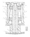
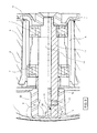
Figure 2 is a cross-sectional view through the axis "X" of the shaft and the spider of the drum according to a first embodiment of the present invention; -
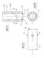
Figure 3 is a median-sectional view through the axis "X" of the head portion of the shaft shown inFigure 2 , as viewed orthogonally thereto; -
Figure 4 is a cross-sectional view orthogonally to the axis "X" of the head portion of the shaft shown inFigure 3 , as viewed according the section plane A-A inFigure 3 ; -
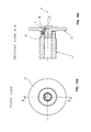
Figure 5 is a planar outer view of the head portion of the shaft shown inFigures 3 and 4 , as viewed from a plane extending parallel to the axis "X"; -
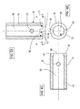
Figure 6A is a similar view as the one appearing inFigure 3 of the head portion of the shaft shown inFigure 5 , in a second embodiment of the present invention; -
Figure 6B is an outer view of the head portion of the shaft shown inFigure 6A , as viewed from the section plane B-B inFigure 6A ; -
Figure 6C is a planar outer view of the head portion of the shaft shown inFigure 6A and 6B , as viewed from a plane extending parallel to the axis "X"; -
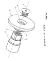
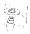
Figure 7A is an exploded perspective view of the shaft-to-pulley coupling in a third embodiment of the present invention; -
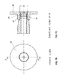
Figure 7B is a front outer view of the shaft shown inFigure 7A ; -
Figure 7C is a cross-sectional view of the shaft according to section plane A-A inFigure 7B ; -
Figure 8A is an exploded perspective view of the shaft-to-pulley coupling in a fourth embodiment of the present invention; -
Figure 8B is a front outer view of the shaft shown inFigure 8A ; -
Figure 8C is a cross-sectional view of the shaft according to section plane A-A inFigure 8B ; -
Figure 8D is a cross-sectional view of the shaft according to section plane B-B inFigure 8C ; -
Figure 8E is a cross-sectional view of the shaft according to section plane C-C inFigure 8D ; -
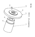
Figure 9A is an exploded perspective view of the shaft-to-pulley coupling in a fifth embodiment of the present invention; -
Figure 9B is a front outer view of the shaft shown inFigure 9A ; -
Figure 9C is a cross-sectional view of the shaft according to section plane A-A inFigure 9B ; -
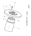
Figure 10A is an exploded perspective view of the shaft-to-pulley coupling in a sixth embodiment of the present invention; -
Figure 10B is a front outer view of the shaft shown inFigure 10A ; -
Figure 10C is a cross-sectional view of the shaft according to section plane A-A inFigure 10B ; -
Figure 11A is an exploded perspective view of the shaft-to-pulley coupling in a seventh embodiment of the present invention; -
Figure 11B is a front outer view of the shaft shown inFigure 11A ; -
Figure 11C is a cross-sectional view of the shaft according to section plane A-A inFigure 11B . - With reference to
Figure 1 , a household-type clothes washing machine according to the prior art comprises arotating shaft 1, into which the clothes to be washed are placed, and which is supported by aspider 2 adapted to support said rotating drum as firmly joined thereto, wherein said spider is rotatably driven by a driving or rotatingshaft 3 that is firmly joined thereto and adapted to drive it to rotate jointly therewith; the clothes washing machine further comprises awashing tub 4 that in a conventional manner contains both the drum and the spider associated thereto, as well as part of saidshaft 3 that extends into said tub by passing through anaperture 5 provided in a vertical wall of said tub. - In a few words, this therefore is what substantially happens and is done in the prior art in general.
- Now, according to the present invention, and with particular reference to
Figures 2 to 4 , said driving shaft is provided in the form of an internallyhollows tube 10, in which theinner cavity 20 is preferably cylindrical, so that theterminal head portion 11 thereof features a double engagement surface, i.e. aninner engagement surface 12 and an outer one 13, both of them cylindrical. - Thus, for the desired shaft-to-drum coupling to be made, the drum is submitted to a usual die-casting process to inglobate, i.e. incorporate in the middle portion thereof not only said
outer surface 13 of theterminal head portion 11 of the shaft, but also enable the die-casting alloy - by flowing into said inner cavity 20 - to cover the innercylindrical surface 12 thereof, thereby inglobating, i.e. incorporating even this surface. - Having both
such surfaces - What is achieved is therefore a general improvement due to both a reduction in the amount of material used and in the overall moment of inertia, and a reduction in processing costs due to the elimination of any machining requirement for providing said knurls.
- On the other hand, the above-described inventive solution is also effective in enabling a particularly favourable embodiment of the coupling to be achieved.
- In fact, referring again to
Figures 2 to 4 , said terminal, internallyhollow head portion 11 is in turn provided with two preferably cylindrical through-channels inner surface 12 with theouter surface 13 of the same head portion. - During the die-casting process which the drum is subjected to, and which inglobates also said
terminal head portion 11, this solution practically enables the alloy flowing into saidinner cavity 20 to also flow into and enter said two through-channels - As a result, the above-described solution enables the alloy to close in on said terminal head portion 11 - during the die-casting process - by also forming a couple of closed-loop configurations, or rings, of alloy extending from the inner cavity of the head portion to the outer surface thereof, as represented by the closed-loop flow-paths indicated at H and K, respectively, in
Figure 2 . - It may then be readily appreciated that the "closed-loop", i.e. ring-like configuration taken by the die-cast alloy on the head portion of the shaft, as well as thereinside, is such as to enable the portion of die-cast alloy located inside said through-
channels - The advantageous nature of this solution may be still further enhanced by a further improvement; with reference to
Figures 6A to 6C , theringshaped surface portion 30 of said innerterminal head 11 facing the interior of the drum is provided with two or more furrow-like recesses - During the die-casting process, also these
furrows - The provision of a shaft formed in the shape of an internally
hollow tube 10, and therefore provided with an inner longitudinal through-cavity 20, allows further for a number of advantageous variants concerning mainly the way in which the pulley used to transmit motion to the driving shaft of the drum is coupled to the same shaft. - With reference to the illustrations in
Figures 7A to 7C , the middle zone of thepulley 40 is provided with anaperture 41 that is arranged so as to lie coaxially with the axis X of saidinner cavity 20, and is provided - on the face thereof facing the drum - with an internally hollow crown-like relief 42 surrounding saidaperture 41. In this connection, it should specially be noticed that: - said crown-
like relief 42 is internally shaped to an angled contour, e.g. having a square cross-section (orthogonal to the axis X), - and the
outer end portion 43 of saidhollow shaft 10 has a contour extending outwardly in a radial direction, which is fully similar to said crown-like relief 42, so that the latter is capable of engaging the same hollow shaft in a stable and precise manner. - Finally, such coupling is further secured in a firm manner by means of an
appropriate bolt 44 that is applied, i.e. screwed tightly into saidaperture 41, wherein the threaded outer surface thereof meshes with the corresponding threadedinner surface 45 of the inner through-cavity 20 of thehollow shaft 10. - With reference now to
Figures 8A to 8E , a different embodiment is based on providing the middle portion of saidpulley 40 with acylindrical protrusion 81 oriented towards thehollow shaft 10 and adapted to engage the inner surface of said through-cavity 20 by the mutual meshing ofcorresponding threads 82. - For such coupling to be firmly and definitively stabilized, in the
outer abutment portion 84 of thehollow shaft 10 there are provided a plurality of furrow-like recesses 85, while a corresponding plurality of appendices, i.e.projections 86 are provided on the inner surface of saidpulley 40 in a position so as to lie externally relative to saidcylindrical protrusion 81. - Said projections are positioned and distributed so as to be able to fit in or correspond to respective ones of said
recesses 85. - Furthermore, for reasons that shall be explained in greater detail below, said projections have a base of a limited height and thickness.
- For the
pulley 20 to be coupled to thehollow shaft 10, saidcylindrical protrusion 81 is screwed into saidhollow shaft 10, as this is shown inFigure 8C ; as the pulley keeps being screwed in, saidprojections 86 first come into contact with and move along by rubbing against said outer abutment portion, and then get distorted so as to fit into respective ones of saidrecesses 85, as this is shown inFigure 8E . - Owing to this, as well as the elastic reaction taking place between said projections and the corresponding recesses, the pulley is firmly and securely joined to the shaft in an effective manner, since said projections, and the pulley as well, are made of a rather "soft" material, whereas said
recesses 85 are of course made of steel. - In practice, said projections tend to "clog up" inside the respective recesses in a definitive and effective manner, considering also the fact that the pulley is already screwed in tightly against the
hollow shaft 10. - With reference now to
Figures 9A to 9C , a different embodiment is based on providing the middle portion of saidpulley 40 with acylindrical protrusion 51 oriented towards thehollow shaft 10 and adapted to engage the inner surface of said through-cavity 20 by the mutual meshing ofcorresponding threads 52. - For such coupling to be firmly and definitively stabilized, in the outer surface of the
pulley 40 there is provided anappropriate bore 53 extending parallel to said axis X, but radially displaced relative thereto. - In the
outer abutment portion 54 of thehollow shaft 10 there is provided acorresponding bore 55, while acorresponding peg 56 adapted to engage both saidbores - For the coupling to be completed, the
pulley 40, and thus saidprotrusion 51, shall first be screwed in to mesh with thethreads 52; saidpeg 56 shall then be inserted in said bores 53 and 55, which must of course be correctly aligned with each other to such purpose, whereupon thesame peg 56 is finally locked with the help of locking means as they are largely known as such in the art. - With reference now to
Figures 10A to 10C , an improved embodiment as compared with the above-described one is based on providing said peg so as it does not extend parallel to the axis X, but is rather inserted under a definite inclination "i" relative. - In this case, therefore, in which - whenever possible and considering that this will certainly not arouse any confusion whatsoever - the same reference numerals are used as in the previously discussed embodiment to indicate the various parts involved, for such coupling to be firmly and definitively stabilized, in the outer surface of the
pulley 40 there is provided anappropriate bore 63 extending no longer parallel to, but rather slanting at an angle "i" relative to said axis X, anyway still radially displaced relative thereto. - In the
outer abutment portion 54 of thehollow shaft 10 there is provided acorresponding bore 64, which is capable of being aligned with the above-citedbore 63, while acorresponding peg 66 adapted to engage both saidbores - The coupling itself is of course completed in the same way as described in connection with the previously considered embodiment; even in this case, in fact, the shaft and the pulley are screwed together.
- However, the result obtained with this embodiment turns out as being more advantageous, since the inclined peg is capable of ensuring its locking action in a twofold direction, i.e. not only in view of preventing any possible rotation of the pulley relative to the
ho0llow shaft 10, but also in view of preventing the same pulley from possibly slipping off the shaft axially. - With reference now to
Figures 11A to 11C , a different embodiment yet is based on providing saidpulley 40 with acentral bore 70, in which the innerannular surface 71 thereof preferably extends axially. - The
corresponding end portion 72 of thehollow shaft 10 is configured so as to extend axially, as well, and the coupling parts are so sized as to enable saidend portion 72 of thehollow shaft 10 to smoothly fit into and precisely couple with said innerannular surface 71 of thecentral bore 70 in thepulley 40. - Upon completing such coupling, the pulley can be effectively locked onto said
hollow shaft 10 against both rotational and axial displacements relative thereto by simply clinching, i.e. riveting down the innerlyhollow end portion 72, thereby widening it out so as to create an outwardly projectinglip 73 that moves into abutting against saidannular surface 71 and presses in a radial direction thereupon. - Owing to such simple operation, which may be limited to a sole clinching or heading process to be carried out with the use of such means as widely known as such in the art, a shaft-to-pulley coupling of a certainly safe, reliable, low-cost and easily done kind.
Claims (8)
- Household clothes washing machine comprising:- a rotating drum (1) for holding the washload,- a spider member (2) integrally supporting said rotating drum,- a rotating or driving shaft integrally joined to said spider member and adapted to transmit a rotational motion thereto,- a tub (4) adapted to accommodate said rotating drum and the spider member (2) integrally associated thereto, and provided with an aperture (5) for the driving shaft to be able to pass therethrough,characterized in that said rotating or driving shaft is provided with a terminal head (11) made in the form of an internally hollow tube (10), the inner, preferably cylindrical cavity (20) of which is provided with an inner surface (12), wherein said spider member (12) of the rotating drum is made of a die-cast alloy provided so as to inglobate both said inner surface (12) and the outer surface (13) of said terminal head (11).
- Household clothes washing machine according to claim 1, characterized in that said inner terminal head (11) of said hollow shaft (10) is provided with at least one through-channel (21, 22) establishing a connection between the outer surface thereof and said inner cavity (20), wherein the part of said die-cast alloy that inglobates forms a closed loop (H, K) joining said inner cavity (20) and the corresponding outer surface thereof by passing through said at least one of said through-channels (21, 22).
- Household clothes washing machine according to claim 1 or 2, characterized in that the portion (30) of said inner terminal head (11) of said hollow shaft (10) facing the interior of the drum is provided with at least one axially open groove-like recess (31, 32), which is filled with said die-cast alloy inglobating said inner terminal head (11) of said shaft.
- Household clothes washing machine according to any of the preceding claims, characterized in that the middle zone of the pulley (40) is provided with an aperture (41) that is arranged so as to lie coaxially with the axis (X) of said hollow shaft (10), and is further provided with an internally hollow crown-like relief (42) that surrounds said aperture (41) and is internally shaped to show a non-cylindrical contour, and in that the outer end portion (43) of said hollow shaft (10) is in turn shaped to show a non-cylindrical contour adapted to fit into said crown-like relief (42) and couple therewith, and in that there are provided locking means, preferably in the form of a bolt (44) adapted to be screwed in from outside so as to pass through said aperture (41) and finally engaging corresponding threads (45) provided on the inner surface of said through-cavity (20).
- Household clothes washing machine according to any of the claims 1 to 3, characterized in that said pulley (40) is provided with a cylindrical protrusion (81) oriented towards the hollow shaft (10), and in that in the outer abutment portion (84) of said hollow shaft (10) there are provided a plurality of furrow-like recesses (85), wherein a corresponding plurality of projections (86) are provided on the surface of said pulley (40) oriented towards the hollow shaft, in a position so as to lie externally relative to said cylindrical protrusion (81), said projections being adapted to fit in and deformably couple with respective ones of said recesses (85).
- Household clothes washing machine according to any of the claims 1 to 3, characterized in that the middle portion of said pulley (40) is provided with a cylindrical protrusion (51) oriented towards said hollow shaft (10) and adapted to engage the inner surface of said through-cavity (20) by the mutual meshing of corresponding threads (52), and in that in the outer surface of the pulley (40) there is provided an appropriate bore (53) extending parallel to said axis (X), but radially displaced relative thereto, and in that in the outer abutment portion (54) of said hollow shaft (10) there is provided a corresponding bore (55), wherein a corresponding peg (56) is adapted to simultaneously engage both said bores (53, 55).
- Household clothes washing machine according to any of the claims 1 to 3, characterized in that the middle portion of said pulley (40) is provided with a cylindrical protrusion (51) oriented towards said hollow shaft (10) and adapted to engage the inner surface of said through-cavity (20) by the mutual meshing of corresponding threads (52), and in that in the outer surface of the pulley (40) there is provided an appropriate bore (63) extending with an inclination at a positive angle (i) relative to said axis (X), and in that in the outer abutment portion (54) of said hollow shaft (10) there is provided a corresponding bore (64), wherein a corresponding peg (56) is adapted to simultaneously engage both said bores (63, 64).
- Household clothes washing machine according to any of the claims 1 to 3, characterized in that said pulley (40) is provided with a central bore (70), in which the inner annular surface (71) thereof is adapted to smoothly fit into and precisely couple with the corresponding outer cylindrical end portion (72) of said hollow shaft (10) through an axial movement, and in that, upon completing such coupling, said outer cylindrical end portion (72) is simply headed or riveted down so as to create an outwardly projecting lip (73) that moves into abutting against said annular surface (71).
Priority Applications (6)
| Application Number | Priority Date | Filing Date | Title |
|---|---|---|---|
| EP07103650A EP1967636B1 (en) | 2007-03-07 | 2007-03-07 | Household clothes washing machine with integrated drum spider |
| PL07103650T PL1967636T3 (en) | 2007-03-07 | 2007-03-07 | Household clothes washing machine with integrated drum spider |
| ES07103650T ES2343975T3 (en) | 2007-03-07 | 2007-03-07 | DOMESTIC WASHER EQUIPPED WITH AN INTEGRATED DRUM CROSSING. |
| DE602007006153T DE602007006153D1 (en) | 2007-03-07 | 2007-03-07 | Household washing machine with integrated drum nozzle |
| AT07103650T ATE466126T1 (en) | 2007-03-07 | 2007-03-07 | HOUSEHOLD WASHING MACHINE WITH INTEGRATED DRUM SOCKET |
| PCT/EP2008/001615 WO2008107124A1 (en) | 2007-03-07 | 2008-02-29 | Household clothes washing machine with integrated drum spider |
Applications Claiming Priority (1)
| Application Number | Priority Date | Filing Date | Title |
|---|---|---|---|
| EP07103650A EP1967636B1 (en) | 2007-03-07 | 2007-03-07 | Household clothes washing machine with integrated drum spider |
Publications (2)
| Publication Number | Publication Date |
|---|---|
| EP1967636A1 true EP1967636A1 (en) | 2008-09-10 |
| EP1967636B1 EP1967636B1 (en) | 2010-04-28 |
Family
ID=38372487
Family Applications (1)
| Application Number | Title | Priority Date | Filing Date |
|---|---|---|---|
| EP07103650A Not-in-force EP1967636B1 (en) | 2007-03-07 | 2007-03-07 | Household clothes washing machine with integrated drum spider |
Country Status (6)
| Country | Link |
|---|---|
| EP (1) | EP1967636B1 (en) |
| AT (1) | ATE466126T1 (en) |
| DE (1) | DE602007006153D1 (en) |
| ES (1) | ES2343975T3 (en) |
| PL (1) | PL1967636T3 (en) |
| WO (1) | WO2008107124A1 (en) |
Cited By (4)
| Publication number | Priority date | Publication date | Assignee | Title |
|---|---|---|---|---|
| EP2412863A1 (en) * | 2010-07-30 | 2012-02-01 | Candy S.p.A. | Tank-basket group for a washing machine, washer dryer or dryer |
| WO2013062315A1 (en) | 2011-10-24 | 2013-05-02 | Lg Electronics Inc. | Washing machine |
| WO2016016114A1 (en) * | 2014-07-30 | 2016-02-04 | BSH Hausgeräte GmbH | Domestic laundry treating machine with a washing drum driven by an electric motor and mounting method |
| US9605370B2 (en) | 2012-10-09 | 2017-03-28 | Lg Electronics Inc. | Washing machine having dual-drum and assembly method thereof |
Families Citing this family (1)
| Publication number | Priority date | Publication date | Assignee | Title |
|---|---|---|---|---|
| US9512551B2 (en) | 2011-10-24 | 2016-12-06 | Lg Electronics Inc. | Washing machine to produce three-dimensional motion |
Citations (5)
| Publication number | Priority date | Publication date | Assignee | Title |
|---|---|---|---|---|
| US2533722A (en) * | 1943-07-14 | 1950-12-12 | J G De Remer Res Corp | Balancing centrifugal drying and washing machine |
| GB877430A (en) * | 1957-10-17 | 1961-09-13 | Hoover Ltd | Improvements relating to washing machines |
| GB972278A (en) * | 1960-05-12 | 1964-10-14 | Hoover Ltd | Improvements relating to washing and spin-drying machines |
| GB1157963A (en) * | 1965-07-17 | 1969-07-09 | Philips Nv | Improvements in Washing Machines and Spin-Drying Machines |
| US4468938A (en) * | 1983-09-12 | 1984-09-04 | General Electric Company | Tubless washing machine |
-
2007
- 2007-03-07 PL PL07103650T patent/PL1967636T3/en unknown
- 2007-03-07 ES ES07103650T patent/ES2343975T3/en active Active
- 2007-03-07 EP EP07103650A patent/EP1967636B1/en not_active Not-in-force
- 2007-03-07 AT AT07103650T patent/ATE466126T1/en not_active IP Right Cessation
- 2007-03-07 DE DE602007006153T patent/DE602007006153D1/en active Active
-
2008
- 2008-02-29 WO PCT/EP2008/001615 patent/WO2008107124A1/en not_active Ceased
Patent Citations (5)
| Publication number | Priority date | Publication date | Assignee | Title |
|---|---|---|---|---|
| US2533722A (en) * | 1943-07-14 | 1950-12-12 | J G De Remer Res Corp | Balancing centrifugal drying and washing machine |
| GB877430A (en) * | 1957-10-17 | 1961-09-13 | Hoover Ltd | Improvements relating to washing machines |
| GB972278A (en) * | 1960-05-12 | 1964-10-14 | Hoover Ltd | Improvements relating to washing and spin-drying machines |
| GB1157963A (en) * | 1965-07-17 | 1969-07-09 | Philips Nv | Improvements in Washing Machines and Spin-Drying Machines |
| US4468938A (en) * | 1983-09-12 | 1984-09-04 | General Electric Company | Tubless washing machine |
Cited By (5)
| Publication number | Priority date | Publication date | Assignee | Title |
|---|---|---|---|---|
| EP2412863A1 (en) * | 2010-07-30 | 2012-02-01 | Candy S.p.A. | Tank-basket group for a washing machine, washer dryer or dryer |
| WO2013062315A1 (en) | 2011-10-24 | 2013-05-02 | Lg Electronics Inc. | Washing machine |
| EP2771506A4 (en) * | 2011-10-24 | 2015-07-15 | Lg Electronics Inc | Washing machine |
| US9605370B2 (en) | 2012-10-09 | 2017-03-28 | Lg Electronics Inc. | Washing machine having dual-drum and assembly method thereof |
| WO2016016114A1 (en) * | 2014-07-30 | 2016-02-04 | BSH Hausgeräte GmbH | Domestic laundry treating machine with a washing drum driven by an electric motor and mounting method |
Also Published As
| Publication number | Publication date |
|---|---|
| PL1967636T3 (en) | 2010-09-30 |
| ES2343975T3 (en) | 2010-08-13 |
| WO2008107124A1 (en) | 2008-09-12 |
| ATE466126T1 (en) | 2010-05-15 |
| DE602007006153D1 (en) | 2010-06-10 |
| EP1967636B1 (en) | 2010-04-28 |
Similar Documents
| Publication | Publication Date | Title |
|---|---|---|
| EP1967636B1 (en) | Household clothes washing machine with integrated drum spider | |
| US8490376B2 (en) | Opening cylinder with clip connection | |
| US8210005B2 (en) | Tub having structurally strengthened rear wall and washing machine with the same therein | |
| US20060101872A1 (en) | Drum type washing machine | |
| EP2468171B1 (en) | Pump mounting in a water-conducting household appliance | |
| AU2005260452B2 (en) | Stator of outer rotor-type motor for drum-type washing machine | |
| EP1733090A2 (en) | Stator of outer rotor-type motor for drum-type washing machine | |
| KR20170024252A (en) | Waching machine | |
| KR101141638B1 (en) | direct drive motor in washing machine | |
| KR100617218B1 (en) | Driving part structure of drum washing machine | |
| CN109790675A (en) | Electric appliance direct-driving motor mounting device | |
| CN107532363B (en) | Assembly with washing drum and unbalance compensating device, household appliance for washing laundry and method for fastening unbalance compensating device | |
| JP2006142034A (en) | Fixing device for combining balance weight with washing tub | |
| KR20050073219A (en) | Structure of driving unit of drum-type washing machine | |
| KR20070049517A (en) | Direct-type Washing Machine Motor | |
| CN209172098U (en) | Transmission mechanism and food cooking machine | |
| KR20010037668A (en) | structure of driving unit in drum-type washing machine | |
| KR101227483B1 (en) | motor for direct drive type washing machine and method for fabricating the same | |
| KR20030046597A (en) | device for combining lifter and spider in drum-type washing machine | |
| KR100595195B1 (en) | Stator of outer rotor type motor for drum washing machine | |
| EP2213778A1 (en) | Manufacturing process of a ballasted tub for front loading laundry treating machines and tub so manufactured | |
| CN208926263U (en) | Dish-washing machine balance weight assembly and dish-washing machine | |
| KR101033576B1 (en) | Stator structure of outer rotor type motor for drum washing machine | |
| TWI668155B (en) | Bicycle chainring | |
| EP2412863B1 (en) | Tank-basket group for a washing machine, washer dryer or dryer |
Legal Events
| Date | Code | Title | Description |
|---|---|---|---|
| PUAI | Public reference made under article 153(3) epc to a published international application that has entered the european phase |
Free format text: ORIGINAL CODE: 0009012 |
|
| AK | Designated contracting states |
Kind code of ref document: A1 Designated state(s): AT BE BG CH CY CZ DE DK EE ES FI FR GB GR HU IE IS IT LI LT LU LV MC MT NL PL PT RO SE SI SK TR |
|
| AX | Request for extension of the european patent |
Extension state: AL BA HR MK RS |
|
| 17P | Request for examination filed |
Effective date: 20081222 |
|
| 17Q | First examination report despatched |
Effective date: 20090213 |
|
| AKX | Designation fees paid |
Designated state(s): AT BE BG CH CY CZ DE DK EE ES FI FR GB GR HU IE IS IT LI LT LU LV MC MT NL PL PT RO SE SI SK TR |
|
| GRAP | Despatch of communication of intention to grant a patent |
Free format text: ORIGINAL CODE: EPIDOSNIGR1 |
|
| GRAS | Grant fee paid |
Free format text: ORIGINAL CODE: EPIDOSNIGR3 |
|
| GRAA | (expected) grant |
Free format text: ORIGINAL CODE: 0009210 |
|
| AK | Designated contracting states |
Kind code of ref document: B1 Designated state(s): AT BE BG CH CY CZ DE DK EE ES FI FR GB GR HU IE IS IT LI LT LU LV MC MT NL PL PT RO SE SI SK TR |
|
| REG | Reference to a national code |
Ref country code: GB Ref legal event code: FG4D |
|
| REG | Reference to a national code |
Ref country code: CH Ref legal event code: EP |
|
| REG | Reference to a national code |
Ref country code: IE Ref legal event code: FG4D |
|
| REF | Corresponds to: |
Ref document number: 602007006153 Country of ref document: DE Date of ref document: 20100610 Kind code of ref document: P |
|
| REG | Reference to a national code |
Ref country code: ES Ref legal event code: FG2A Ref document number: 2343975 Country of ref document: ES Kind code of ref document: T3 |
|
| REG | Reference to a national code |
Ref country code: NL Ref legal event code: VDEP Effective date: 20100428 |
|
| LTIE | Lt: invalidation of european patent or patent extension |
Effective date: 20100428 |
|
| REG | Reference to a national code |
Ref country code: PL Ref legal event code: T3 |
|
| PG25 | Lapsed in a contracting state [announced via postgrant information from national office to epo] |
Ref country code: SE Free format text: LAPSE BECAUSE OF FAILURE TO SUBMIT A TRANSLATION OF THE DESCRIPTION OR TO PAY THE FEE WITHIN THE PRESCRIBED TIME-LIMIT Effective date: 20100428 Ref country code: NL Free format text: LAPSE BECAUSE OF FAILURE TO SUBMIT A TRANSLATION OF THE DESCRIPTION OR TO PAY THE FEE WITHIN THE PRESCRIBED TIME-LIMIT Effective date: 20100428 Ref country code: LT Free format text: LAPSE BECAUSE OF FAILURE TO SUBMIT A TRANSLATION OF THE DESCRIPTION OR TO PAY THE FEE WITHIN THE PRESCRIBED TIME-LIMIT Effective date: 20100428 |
|
| PG25 | Lapsed in a contracting state [announced via postgrant information from national office to epo] |
Ref country code: AT Free format text: LAPSE BECAUSE OF FAILURE TO SUBMIT A TRANSLATION OF THE DESCRIPTION OR TO PAY THE FEE WITHIN THE PRESCRIBED TIME-LIMIT Effective date: 20100428 Ref country code: LV Free format text: LAPSE BECAUSE OF FAILURE TO SUBMIT A TRANSLATION OF THE DESCRIPTION OR TO PAY THE FEE WITHIN THE PRESCRIBED TIME-LIMIT Effective date: 20100428 Ref country code: IS Free format text: LAPSE BECAUSE OF FAILURE TO SUBMIT A TRANSLATION OF THE DESCRIPTION OR TO PAY THE FEE WITHIN THE PRESCRIBED TIME-LIMIT Effective date: 20100828 Ref country code: FI Free format text: LAPSE BECAUSE OF FAILURE TO SUBMIT A TRANSLATION OF THE DESCRIPTION OR TO PAY THE FEE WITHIN THE PRESCRIBED TIME-LIMIT Effective date: 20100428 Ref country code: SI Free format text: LAPSE BECAUSE OF FAILURE TO SUBMIT A TRANSLATION OF THE DESCRIPTION OR TO PAY THE FEE WITHIN THE PRESCRIBED TIME-LIMIT Effective date: 20100428 |
|
| PG25 | Lapsed in a contracting state [announced via postgrant information from national office to epo] |
Ref country code: CY Free format text: LAPSE BECAUSE OF FAILURE TO SUBMIT A TRANSLATION OF THE DESCRIPTION OR TO PAY THE FEE WITHIN THE PRESCRIBED TIME-LIMIT Effective date: 20100602 |
|
| PG25 | Lapsed in a contracting state [announced via postgrant information from national office to epo] |
Ref country code: EE Free format text: LAPSE BECAUSE OF FAILURE TO SUBMIT A TRANSLATION OF THE DESCRIPTION OR TO PAY THE FEE WITHIN THE PRESCRIBED TIME-LIMIT Effective date: 20100428 Ref country code: PT Free format text: LAPSE BECAUSE OF FAILURE TO SUBMIT A TRANSLATION OF THE DESCRIPTION OR TO PAY THE FEE WITHIN THE PRESCRIBED TIME-LIMIT Effective date: 20100830 Ref country code: GR Free format text: LAPSE BECAUSE OF FAILURE TO SUBMIT A TRANSLATION OF THE DESCRIPTION OR TO PAY THE FEE WITHIN THE PRESCRIBED TIME-LIMIT Effective date: 20100729 Ref country code: DK Free format text: LAPSE BECAUSE OF FAILURE TO SUBMIT A TRANSLATION OF THE DESCRIPTION OR TO PAY THE FEE WITHIN THE PRESCRIBED TIME-LIMIT Effective date: 20100428 |
|
| PG25 | Lapsed in a contracting state [announced via postgrant information from national office to epo] |
Ref country code: SK Free format text: LAPSE BECAUSE OF FAILURE TO SUBMIT A TRANSLATION OF THE DESCRIPTION OR TO PAY THE FEE WITHIN THE PRESCRIBED TIME-LIMIT Effective date: 20100428 Ref country code: RO Free format text: LAPSE BECAUSE OF FAILURE TO SUBMIT A TRANSLATION OF THE DESCRIPTION OR TO PAY THE FEE WITHIN THE PRESCRIBED TIME-LIMIT Effective date: 20100428 Ref country code: CZ Free format text: LAPSE BECAUSE OF FAILURE TO SUBMIT A TRANSLATION OF THE DESCRIPTION OR TO PAY THE FEE WITHIN THE PRESCRIBED TIME-LIMIT Effective date: 20100428 Ref country code: BE Free format text: LAPSE BECAUSE OF FAILURE TO SUBMIT A TRANSLATION OF THE DESCRIPTION OR TO PAY THE FEE WITHIN THE PRESCRIBED TIME-LIMIT Effective date: 20100428 |
|
| PLBE | No opposition filed within time limit |
Free format text: ORIGINAL CODE: 0009261 |
|
| STAA | Information on the status of an ep patent application or granted ep patent |
Free format text: STATUS: NO OPPOSITION FILED WITHIN TIME LIMIT |
|
| RAP2 | Party data changed (patent owner data changed or rights of a patent transferred) |
Owner name: ELECTROLUX HOME PRODUCTS CORPORATION N.V. |
|
| 26N | No opposition filed |
Effective date: 20110131 |
|
| PG25 | Lapsed in a contracting state [announced via postgrant information from national office to epo] |
Ref country code: MC Free format text: LAPSE BECAUSE OF NON-PAYMENT OF DUE FEES Effective date: 20110331 |
|
| REG | Reference to a national code |
Ref country code: CH Ref legal event code: PL |
|
| PG25 | Lapsed in a contracting state [announced via postgrant information from national office to epo] |
Ref country code: MT Free format text: LAPSE BECAUSE OF FAILURE TO SUBMIT A TRANSLATION OF THE DESCRIPTION OR TO PAY THE FEE WITHIN THE PRESCRIBED TIME-LIMIT Effective date: 20100428 |
|
| REG | Reference to a national code |
Ref country code: IE Ref legal event code: MM4A |
|
| PG25 | Lapsed in a contracting state [announced via postgrant information from national office to epo] |
Ref country code: IE Free format text: LAPSE BECAUSE OF NON-PAYMENT OF DUE FEES Effective date: 20110307 Ref country code: CH Free format text: LAPSE BECAUSE OF NON-PAYMENT OF DUE FEES Effective date: 20110331 Ref country code: LI Free format text: LAPSE BECAUSE OF NON-PAYMENT OF DUE FEES Effective date: 20110331 |
|
| REG | Reference to a national code |
Ref country code: FR Ref legal event code: CA Effective date: 20120116 |
|
| PGFP | Annual fee paid to national office [announced via postgrant information from national office to epo] |
Ref country code: IT Payment date: 20120326 Year of fee payment: 6 |
|
| PGFP | Annual fee paid to national office [announced via postgrant information from national office to epo] |
Ref country code: GB Payment date: 20130321 Year of fee payment: 7 Ref country code: ES Payment date: 20130326 Year of fee payment: 7 Ref country code: DE Payment date: 20130321 Year of fee payment: 7 Ref country code: FR Payment date: 20130408 Year of fee payment: 7 |
|
| PG25 | Lapsed in a contracting state [announced via postgrant information from national office to epo] |
Ref country code: LU Free format text: LAPSE BECAUSE OF NON-PAYMENT OF DUE FEES Effective date: 20110307 |
|
| PGFP | Annual fee paid to national office [announced via postgrant information from national office to epo] |
Ref country code: PL Payment date: 20130225 Year of fee payment: 7 |
|
| PG25 | Lapsed in a contracting state [announced via postgrant information from national office to epo] |
Ref country code: BG Free format text: LAPSE BECAUSE OF FAILURE TO SUBMIT A TRANSLATION OF THE DESCRIPTION OR TO PAY THE FEE WITHIN THE PRESCRIBED TIME-LIMIT Effective date: 20100728 Ref country code: TR Free format text: LAPSE BECAUSE OF FAILURE TO SUBMIT A TRANSLATION OF THE DESCRIPTION OR TO PAY THE FEE WITHIN THE PRESCRIBED TIME-LIMIT Effective date: 20100428 |
|
| PG25 | Lapsed in a contracting state [announced via postgrant information from national office to epo] |
Ref country code: HU Free format text: LAPSE BECAUSE OF FAILURE TO SUBMIT A TRANSLATION OF THE DESCRIPTION OR TO PAY THE FEE WITHIN THE PRESCRIBED TIME-LIMIT Effective date: 20100428 |
|
| REG | Reference to a national code |
Ref country code: DE Ref legal event code: R119 Ref document number: 602007006153 Country of ref document: DE |
|
| GBPC | Gb: european patent ceased through non-payment of renewal fee |
Effective date: 20140307 |
|
| REG | Reference to a national code |
Ref country code: FR Ref legal event code: ST Effective date: 20141128 |
|
| REG | Reference to a national code |
Ref country code: DE Ref legal event code: R119 Ref document number: 602007006153 Country of ref document: DE Effective date: 20141001 |
|
| PG25 | Lapsed in a contracting state [announced via postgrant information from national office to epo] |
Ref country code: GB Free format text: LAPSE BECAUSE OF NON-PAYMENT OF DUE FEES Effective date: 20140307 Ref country code: FR Free format text: LAPSE BECAUSE OF NON-PAYMENT OF DUE FEES Effective date: 20140331 Ref country code: DE Free format text: LAPSE BECAUSE OF NON-PAYMENT OF DUE FEES Effective date: 20141001 |
|
| PG25 | Lapsed in a contracting state [announced via postgrant information from national office to epo] |
Ref country code: IT Free format text: LAPSE BECAUSE OF NON-PAYMENT OF DUE FEES Effective date: 20140307 |
|
| PG25 | Lapsed in a contracting state [announced via postgrant information from national office to epo] |
Ref country code: PL Free format text: LAPSE BECAUSE OF NON-PAYMENT OF DUE FEES Effective date: 20140307 |
|
| REG | Reference to a national code |
Ref country code: PL Ref legal event code: LAPE |
|
| PG25 | Lapsed in a contracting state [announced via postgrant information from national office to epo] |
Ref country code: ES Free format text: LAPSE BECAUSE OF NON-PAYMENT OF DUE FEES Effective date: 20140308 |