EP1967250A1 - CO2 recovery system and solid-particles removing method for use in the same - Google Patents
CO2 recovery system and solid-particles removing method for use in the same Download PDFInfo
- Publication number
- EP1967250A1 EP1967250A1 EP08150341A EP08150341A EP1967250A1 EP 1967250 A1 EP1967250 A1 EP 1967250A1 EP 08150341 A EP08150341 A EP 08150341A EP 08150341 A EP08150341 A EP 08150341A EP 1967250 A1 EP1967250 A1 EP 1967250A1
- Authority
- EP
- European Patent Office
- Prior art keywords
- backwash water
- solid
- particles
- solution
- solid particles
- Prior art date
- Legal status (The legal status is an assumption and is not a legal conclusion. Google has not performed a legal analysis and makes no representation as to the accuracy of the status listed.)
- Granted
Links
Images



Classifications
-
- B—PERFORMING OPERATIONS; TRANSPORTING
- B01—PHYSICAL OR CHEMICAL PROCESSES OR APPARATUS IN GENERAL
- B01D—SEPARATION
- B01D53/00—Separation of gases or vapours; Recovering vapours of volatile solvents from gases; Chemical or biological purification of waste gases, e.g. engine exhaust gases, smoke, fumes, flue gases, aerosols
- B01D53/34—Chemical or biological purification of waste gases
- B01D53/73—After-treatment of removed components
-
- B—PERFORMING OPERATIONS; TRANSPORTING
- B01—PHYSICAL OR CHEMICAL PROCESSES OR APPARATUS IN GENERAL
- B01D—SEPARATION
- B01D53/00—Separation of gases or vapours; Recovering vapours of volatile solvents from gases; Chemical or biological purification of waste gases, e.g. engine exhaust gases, smoke, fumes, flue gases, aerosols
- B01D53/14—Separation of gases or vapours; Recovering vapours of volatile solvents from gases; Chemical or biological purification of waste gases, e.g. engine exhaust gases, smoke, fumes, flue gases, aerosols by absorption
- B01D53/1425—Regeneration of liquid absorbents
-
- B—PERFORMING OPERATIONS; TRANSPORTING
- B01—PHYSICAL OR CHEMICAL PROCESSES OR APPARATUS IN GENERAL
- B01D—SEPARATION
- B01D53/00—Separation of gases or vapours; Recovering vapours of volatile solvents from gases; Chemical or biological purification of waste gases, e.g. engine exhaust gases, smoke, fumes, flue gases, aerosols
- B01D53/14—Separation of gases or vapours; Recovering vapours of volatile solvents from gases; Chemical or biological purification of waste gases, e.g. engine exhaust gases, smoke, fumes, flue gases, aerosols by absorption
- B01D53/1456—Removing acid components
- B01D53/1475—Removing carbon dioxide
-
- B—PERFORMING OPERATIONS; TRANSPORTING
- B01—PHYSICAL OR CHEMICAL PROCESSES OR APPARATUS IN GENERAL
- B01D—SEPARATION
- B01D53/00—Separation of gases or vapours; Recovering vapours of volatile solvents from gases; Chemical or biological purification of waste gases, e.g. engine exhaust gases, smoke, fumes, flue gases, aerosols
- B01D53/34—Chemical or biological purification of waste gases
- B01D53/46—Removing components of defined structure
- B01D53/62—Carbon oxides
-
- Y—GENERAL TAGGING OF NEW TECHNOLOGICAL DEVELOPMENTS; GENERAL TAGGING OF CROSS-SECTIONAL TECHNOLOGIES SPANNING OVER SEVERAL SECTIONS OF THE IPC; TECHNICAL SUBJECTS COVERED BY FORMER USPC CROSS-REFERENCE ART COLLECTIONS [XRACs] AND DIGESTS
- Y02—TECHNOLOGIES OR APPLICATIONS FOR MITIGATION OR ADAPTATION AGAINST CLIMATE CHANGE
- Y02C—CAPTURE, STORAGE, SEQUESTRATION OR DISPOSAL OF GREENHOUSE GASES [GHG]
- Y02C20/00—Capture or disposal of greenhouse gases
- Y02C20/40—Capture or disposal of greenhouse gases of CO2
-
- Y—GENERAL TAGGING OF NEW TECHNOLOGICAL DEVELOPMENTS; GENERAL TAGGING OF CROSS-SECTIONAL TECHNOLOGIES SPANNING OVER SEVERAL SECTIONS OF THE IPC; TECHNICAL SUBJECTS COVERED BY FORMER USPC CROSS-REFERENCE ART COLLECTIONS [XRACs] AND DIGESTS
- Y02—TECHNOLOGIES OR APPLICATIONS FOR MITIGATION OR ADAPTATION AGAINST CLIMATE CHANGE
- Y02P—CLIMATE CHANGE MITIGATION TECHNOLOGIES IN THE PRODUCTION OR PROCESSING OF GOODS
- Y02P20/00—Technologies relating to chemical industry
- Y02P20/151—Reduction of greenhouse gas [GHG] emissions, e.g. CO2
Definitions
- the present invention relates to a CO 2 recovery system and a solid-particle removing method for use in the CO 2 recovery system that can filter out solid particles contained in CO 2 -absorbing solution that is used for removing CO 2 from exhaust gas and then remove the filtered-out solid particles.
- CO 2 emitted into the atmosphere has been considered the prime cause of the greenhouse effect.
- CO 2 sources range various fields of human activities, including burning of fossil fuels, and demands to suppress their CO 2 emission from these sources are on constant increase.
- scientists have energetically studied means and methods for suppressing emission of CO 2 from power generation facilities such as power generation stations which use an enormous amount of fossil fuels.
- One of the methods includes bringing combustion exhaust gas of boilers into contact with an amine-based CO 2 -absorbing solution. This method allows removal and recovery of CO 2 from the combustion exhaust gas.
- Another method includes storing recovered CO 2 , i.e., not returning the recovered CO 2 to the atmosphere.
- Japanese Patent Application Laid-Open No. H5-245339 discloses a method of contacting the combustion exhaust gas with the CO 2 -absorbing solution in an absorption tower, heating an absorbing solution having absorbed CO 2 in a regeneration tower, and releasing CO 2 , regenerating the absorbing solution, and circulating the regenerated absorbing solution to the absorption tower again to be reused.
- CO 2 -containing exhaust gas 1002 discharged from a factory 1001 is cooled with coolant water 1003 in a cooling tower 1004.
- the factory 1001 can be a boiler.
- the cooled CO 2 -containing exhaust gas 1002 is then conveyed to an absorption tower 1006 where it is brought into countercurrent contact with CO 2 -absorbing solution 1005.
- the CO 2 -absorbing solution 1005 can be an alkanolamine-based solution.
- CO 2 in the CO 2 -containing exhaust gas 1002 is absorbed into the CO 2 -absorbing solution 1005, that is, CO2 is removed from the CO 2 -containing exhaust gas 1002.
- the CO 2 -absorbing solution 1005 containing CO 2 (hereinafter, "rich solution 1007") is conveyed to a regeneration tower 1008.
- the rich solution 1007 drips downward in the regeneration tower 1008.
- the rich solution 1007 reaches a lower portion of the regeneration tower 1008, most of the CO 2 absorbed in the rich solution 1007 is released, and the rich solution 1007 turns into lean solution 1009 capable of working as the CO 2 -absorbing solution 1005.
- the lean solution 1009 is heated with saturated steam 1030 in a regeneration heater 1014. Thereafter, the lean solution 1009 is returned to the absorption tower 1006 and it is reused as the CO 2 -absorbing solution 1005.
- the saturated steam 1030 after use is discharged from the regeneration heater 1014 as steam concentrated water 1031.
- thermostable salt mixes with the lean solution 1009, which creates various issues.
- the thermostable salt cannot be removed under normal conditions in a course of producing the lean solution 1009 from the rich solution 1007, so that the thermostable salt accumulates in the system while the lean solution 1009 circulates.
- the CO 2 recovery system 1000 includes a reclaimer 1040 to which the lean solution 1009 that is produced in the regeneration tower 1008 is supplied.
- the reclaimer 1040 heats the lean solution 1009 to produce a condensed depleted material such as a salt. The condensed depleted material is then removed.
- the lean solution 1009 passing through a lean-solution supply line 1022 is extracted through an extracting line 1041 that is stretched from the lean-solution supply line 1022 to the reclaimer 1040.
- the reclaimer 1040 receives saturated steam 1046 from a saturated-steam supply line 1045 into a saturated-steam supply pipe 1050 and heats the lean solution 1009 with the saturated steam 1046.
- the depleted material is removed from the extracted lean solution 1009 in the reclaimer 1040.
- the lean solution 1009 is heated in the reclaimer 1040 to, for example, 130°C to 150°C, so that vaporized CO 2 -absorbing solution 1047 is obtained from the lean solution 1009.
- the vaporized CO 2 -absorbing solution 1047 is supplied to the lower portion of the regeneration tower 1008.
- a condensed waste-product accumulated on a bottom of the reclaimer 1040 is removed from the system, for example, the boiler, for example, by pumping with a pump.
- solid particles such as soot dust or fly ashes (coal ashes) remain un-removed by a desulfurization device (not shown) are removed in the absorption tower 1006.
- a part of the solid particles still remain un-removed in the lean solution 1009.
- the solid particles in the lean solution 1009 are filtered out by a filtering member, and the filtered-out solid particles are then removed.
- the filtering member after use is replaced with a new one and the old filtering member is discarded as a waste product.
- the filtering member can be, for example, a cartridge filter or a precoat filter.
- the amount of the exhaust gas from the CO 2 recovery system 1000 is, for example, about 1,000,000 Nm3/h and the amount of dust out of the exhaust gas is, for example, about 5.0 mg/Nm3, about 40% of the dusts is removed in the cooling tower 1004 and the desulfurization device (not shown) and about 60% (i.e., the remaining dust) is removed in the absorption tower 1006.
- a maximum collectable dust-amount of a typical filter is about from 100 grams to 200 grams per bottle. It means that 15 to 30 filters are replaced every hour. Such frequent filter replacement is impossible in practice, and the conventional filtering cannot be used in the large-capacity CO 2 recovery system.
- the lean solution 1009 contains the CO 2 -absorbing solution 1005 that contains amine. Therefore, a chemical oxygen demand (COD) of the lean solution 1009 is high, and the lean solution 1009 cannot be drained out as effluent.
- CO 2 -absorbing solution 1005 that contains amine. Therefore, a chemical oxygen demand (COD) of the lean solution 1009 is high, and the lean solution 1009 cannot be drained out as effluent.
- the present invention has been achieved to solve the above problems in the conventional technology and it is an object of the present invention to provide a CO 2 recovery system capable of recovering a large amount of CO 2 thereby producing dust to be removed in the absorption tower as much as, for example, 3.0 kg/h and a solid-particles removing method for use in the CO 2 recovery system that can remove the solid particles from the lean solution.
- a CO 2 recovery system including an absorption tower that receives CO 2 -containing gas and CO 2 -absorbing solution, and causes the CO 2 -containing gas to come in contact with the CO 2 -absorbing solution to produce CO 2 rich solution, and a regeneration tower that receives the rich solution and produces lean solution from the rich solution by removing CO 2 from the rich solution.
- the CO 2 recovery system includes a filtering unit that includes an outer casing and at least one filter member, wherein when a solution contained in the regeneration tower is supplied to the outer casing the filter member filters out solid particles contained in the solution; a washing unit that washes out with backwash water the solid particles filtered out by the filter member; and an evaporating unit that receives the backwash water containing the solid particles, and heats received backwash water thereby obtaining solid-particles concentrated backwash water.
- a solid-particles removing method for use in a CO 2 recovery system including an absorption tower that receives CO 2 -containing gas and CO 2 -absorbing solution, and causes the CO 2 -containing gas to come in contact with the CO 2 -absorbing solution to produce CO 2 rich solution, and a regeneration tower that receives the rich solution and produces lean solution from the rich solution by removing CO 2 from the rich solution.
- the solid-particles removing method includes filtering a solution contained in the regeneration tower contained thereby filtering out solid particles contained in the solution by a filtering member; washing out with backwash water the solid particles that are filtered out by the filtering member; heating by an evaporating unit the backwash water containing the solid particles thereby obtaining concentrated solid particles; and removing the concentrated solid particles.
- Fig. 1 is a schematic diagram of a CO 2 recovery system 10A according to a first embodiment of the present invention
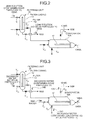
- Fig. 2 is a schematic diagram of a filtering unit 15 shown in Fig. 1 during filtering a lean solution 1009A
- Fig. 3 is a schematic diagram of the filtering unit 15 during receiving backwash water 14A into the filtering unit 15. Parts corresponding to those in the CO 2 recovery system 1000 are denoted with the same reference numerals, and the same description is not repeated.
- the factory 1001 and the cooling tower 1004 are not shown.
- the CO 2 recovery system 10A includes the absorption tower 1006 and the regeneration tower 1008.
- the CO 2 -containing exhaust gas 1002 comes in contact with the CO 2 -absorbing solution 1005 for absorbing CO 2 therein to remove the CO 2 from the CO 2 -containing exhaust gas 1002.
- the regeneration tower 1008 the rich solution 1007 containing CO 2 is regenerated and thermal exchange is performed.
- the lean solution 1009 that is produced after removing CO 2 from the rich solution 1007 in the regeneration tower 1008 (regenerated CO 2 -absorbing solution) returns to the absorption tower 1006 as the CO 2 -absorbing solution 1005.
- the CO 2 recovery system 10A additionally includes the filtering unit 15 and an evaporator 16A.
- the filtering unit 15 includes a filter 13 and a filter casing 12.
- the filter 13 filters out solid particles 11, such as soot dust or fly ashes, contained in the lean solution 1009A.
- the lean solution 1009A is a part of the lean solution 1009 passing through the lean-solution supply line 1022.
- the solid particles 11 filtered out by the filter 13 are washed out with the backwash water 14A that is supplied to the filter casing 12.
- the evaporator 16A is located downstream of the filtering unit 15.
- the evaporator 16A heats the backwash water 14A containing the solid particles 11 (hereinafter, "backwash water 14B") to concentrate the solid particles 11 in the backwash water 14B.
- the filtering unit 15 filters out the solid particles 11 remain un-removed in the lean solution 1009A with the filter 13 that is accommodated in the filter casing 12.
- lean solution 1009B the lean solution not containing the solid particles 11
- An outlined valve-mark shown in Figs. 2 and 3 represents an open valve, and a filled valve-mark represents a closed valve.
- valves V 11 and V 12 are open and valves V 13 and V 14 are closed.
- the filtering unit 15 receives the lean solution 1009A in the filter casing 12, and causes the filter 13 to filter out the solid particles 11 contained in the lean solution 1009A thereby producing the lean solution 1009B.
- the lean solution 1009B is then supplied to the lean-solution supply line 1022.
- the filtering unit 15 has a backwash function to wash out the solid particles 11 filtered out by the filter 13 with the backwash water 14A that is received in the filter casing 12.
- the backwash water 14A flows in the filter casing 12, for example, from an outer surface to an inner surface of the filter 13, that is, a direction reverse to a flow of the lean solution 1009A in the filter casing 12, so that the solid particles 11 attached on the inner surface or inside of the filter 13 are removed from the filter 13.
- the solid particles 11 attached on the filter 13 are contained in the backwash water 14A, that is, the solid particles 11 are washed away from the filter 13.
- the valves V 11 and V 12 are closed and the valves V 13 and V 14 are open.
- the backwash water 14A is supplied to the filtering unit 15, and then the solid particles 11 are contained in the backwash water 14A, that is, the solid particles 11 are washed away from the filter 13.
- the backwash water 14A containing the solid particles 11 i.e., the backwash water 14B is discharged from the filtering unit 15.
- the evaporator 16A that is located downstream of the filtering unit 15 for heating the backwash water 14B to concentrate the solid particles 11 in the backwash water 14B.
- the evaporator 16A Upon receiving the backwash water 14B, the evaporator 16A receives saturated steam 1046A passing through a saturated-steam supply line 1045A in a vaporization pipe 17 and heats the backwash water 14B with the saturated steam 1046A thereby obtaining a backwash water 14C that contains the concentrated solid particles 11.
- the backwash water 14B can contain the CO 2 -absorbing solution 1005.
- the evaporator 16A vaporizes the CO 2 -absorbing solution 1005 contained in the backwash water 14B thereby obtaining the vaporized CO 2 -absorbing solution 1047. It means that, the evaporator 16A can heat the backwash water 14B to concentrate the solid particles 11 in the backwash water 14B while separating the CO 2 -absorbing solution 1005 from the backwash water 14B.
- the evaporator 16A also receives water 1043.
- the concentration of the CO 2 -absorbing solution 1005 in the backwash water 14B is high.
- the evaporator 16A receives the water 1043 thereby vaporizing the CO 2 -absorbing solution 1005 from the backwash water 14B having a low CO 2 -absorbing solution 1005 concentration.
- the backwash water 14B turns to the backwash water 14C that contains the concentrated solid particles 11 in the evaporator 16A.
- the backwash water 14C is then discharged from the evaporator 16A.
- a typical reclaimer uses, for example, two kilograms to five kilograms of steam per hour to concentrate suspensoid ingredients contained in the lean solution.
- the evaporator 16A uses, for example, two kilograms to three kilograms of steam as the saturated steam 1046A and the water 1043.
- the evaporator 16A vaporizes the CO 2 -absorbing solution 1005 at a temperature lower than that in the reclaimer 1040 while concentrating the suspensoid ingredients contained in the backwash water 14B. This is why the evaporator 16A is provided separated from the reclaimer 1040. As described later, the CO 2 -absorbing solution 1005 remaining un-removed in the backwash water 14C is vaporized in the reclaimer 1040 that is located downstream of the evaporator 16A. The concentrated solid particles 11 contained in the backwash water 14C are then removed.
- valves V 21 when valves V 21 is open, the evaporator 16A receives the water 1043 via the valve V 21 and heats the backwash water 14B with the saturated steam 1046 passing through the saturated-steam supply line 1045A.
- valve V 22 When valve V 22 is open, the vaporized CO 2 -absorbing solution 1047 that is obtained from the backwash water 14B flows via the valve V 22 to the regeneration tower 1008 passing through vaporized CO 2 -absorbing solution supply lines 1048A and 1048C and accumulates on a bottom of the regeneration tower 1008.
- valve V 23 When valve V 23 is open, the backwash water 14C is discharged from the evaporator 16A.
- the CO 2 recovery system 10A includes the reclaimer 1040 that is located downstream of the evaporator 16A.
- the reclaimer 1040 Upon receiving the backwash water 14C from the evaporator 16A, the reclaimer 1040 receives saturated steam 1046B passing through a saturated-steam supply line 1045B and heats the backwash water 14C with the saturated steam 1046B thereby vaporizing the CO 2 -absorbing solution 1005 remaining un-removed in the backwash water 14C and concentrating the solid particles 11 in the backwash water 14C. The concentrated solid particles are then removed.
- valve V 3 When a valve V 3 is open, the CO 2 -absorbing solution 1005 in the vapor state (the vaporized CO 2 -absorbing solution 1047) flows via the valve V 3 to the regeneration tower 1008 passing through the vaporized CO 2 -absorbing solution supply lines 1048B and 1048C and accumulates on the bottom of the regeneration tower 1008.
- a valve V 4 When a valve V 4 is open, the solid particles 11 concentrated from the backwash water 14C are removed from the reclaimer 1040.
- the CO 2 recovery system 10A can include, as shown in Fig. 4 , a clarifier 20 arranged between the filtering unit 15 and the evaporator 16A to precipitate a part of the solid particles 11 contained in the backwash water 14B. The precipitated part is then removed. More particularly, the backwash water 14B is supplied to a clarifier casing 21 of the clarifier 20. A part of the solid particles 11 contained in the backwash water 14B is precipitated in the clarifier casing 21, and the precipitated part is then removed. The evaporator 16A receives the backwash water 14B containing a less amount of the solid particles 11. This allows reducing the load on the evaporator 16A.
- the filtering unit 15 filters out with the filter 13 the solid particles 11 contained in the lean solution 1009, and the solid particles 11 attached onto the surface of the filter 13 is washed out with the backwash water 14A. This enables the filtering unit 15 to filter out a large amount of the solid particles 11 without replacement. Thereafter, the evaporator 16A vaporizes the CO 2 -absorbing solution 1005 contained in the backwash water 14B and concentrates the solid particles 11. The concentrated solid particles 11 are then removed.
- a hollow fiber membrane, a sintered metallic filter, or a microfiltration membrane is used as the filter 13.
- Another filter can be used as the filter 13.
- the backwash water 14A is used for washing out the solid particles 11 from the filter 13. It is allowable to use, for example, compressed air for removing the solid particles 11 from the filter 13 instead of the backwash water 14A.
- solution from which the solid particles 11 are removed is the lean solution 1009A that is partially extracted from the lean solution 1009 passing through the lean-solution supply line 1022. It is allowable to use a part of the rich solution 1007 instead of the lean solution 1009.
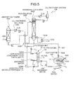
- Fig. 5 is a schematic diagram of a CO 2 recovery system 10B according to a second embodiment of the present invention. Parts corresponding to those in the CO 2 recovery system 10A according to the first embodiment and the conventional CO 2 recovery system 1000 are denoted with the same reference numerals, and the same description is not repeated. The factory 1001 and the cooling tower 1004 are not shown.
- An evaporator 16B in the CO 2 recovery system 10B functions as both the evaporator 16A and the reclaimer 1040. More particularly, the evaporator 16B heats the backwash water 14B thereby vaporizing the CO 2 -absorbing solution 1005 contained in the backwash water 14B and concentrates the solid particles 11 in the backwash water 14B. The concentrated solid particles 11 are then removed.
- the evaporator 16B heats the backwash water 14B thereby vaporizing the CO 2 -absorbing solution 1005 from the backwash water 14B and concentrating the solid particles 11 in the backwash water 14B.
- both vaporization of the CO 2 -absorbing solution 1005 remain in the backwash water 14B and concentration of the solid particles 11 in the backwash water 14B are performed only in the evaporator 16B.
- the evaporator 16B has functions of vaporizing the CO 2 -absorbin solution 1005 from the backwash water 14B and concentrating the solid particles 11 in the backwash water 14B with heat, which allows reducing a size of the CO 2 recovery system 10B as compared to the CO 2 recovery system 10A that includes the evaporator 16A and the reclaimer 1040 separately.
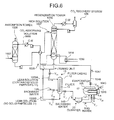
- the CO 2 recovery system 10B can include, as shown in Fig. 6 , the clarifier 20 arranged between the filtering unit 15 and the evaporator 16B to remove a precipitated portion of the solid particles 11 from the backwash water 14B.
- the backwash water 14B which contains the solid particles 11, is supplied to the clarifier casing 21. A part precipitated in the clarifier casing 21 out of the solid particles 11 contained in the backwash water 14B is then removed.
- the evaporator 16B receives the backwash water 14B containing a less amount of the solid particles 11. This allows reducing the load on the evaporator 16B.
- a filtering unit filters out with a backwashable filter solid particles contained in at least one of the lean solution and the rich solution, and the solid particles filtered out by the filter are washed out with backwash water. Thereafter, an evaporator vaporizes the CO 2 -absorbing solution contained in the backwash water and concentrates the solid particles contained in the backwash water. The concentrated solid particles are then removed. Even if the CO 2 recovery system is so large that it can produce soot dust to be removed as much as, for example, 3.0 kg/h in the absorption tower, the large amount of the solid particles contained in the lean solution can be removed continuously.
Landscapes
- Chemical & Material Sciences (AREA)
- Engineering & Computer Science (AREA)
- General Chemical & Material Sciences (AREA)
- Chemical Kinetics & Catalysis (AREA)
- Oil, Petroleum & Natural Gas (AREA)
- Analytical Chemistry (AREA)
- Environmental & Geological Engineering (AREA)
- Health & Medical Sciences (AREA)
- Biomedical Technology (AREA)
- Gas Separation By Absorption (AREA)
- Treating Waste Gases (AREA)
- Separation Using Semi-Permeable Membranes (AREA)
- Vaporization, Distillation, Condensation, Sublimation, And Cold Traps (AREA)
- Carbon And Carbon Compounds (AREA)
Abstract
Description
- The present invention relates to a CO2 recovery system and a solid-particle removing method for use in the CO2 recovery system that can filter out solid particles contained in CO2-absorbing solution that is used for removing CO2 from exhaust gas and then remove the filtered-out solid particles.
- In recent years the greenhouse effect has been pointed out as one of causes of the global warming, and a countermeasure against it is urgently required internationally to protect global environment. CO2 emitted into the atmosphere has been considered the prime cause of the greenhouse effect. CO2 sources range various fields of human activities, including burning of fossil fuels, and demands to suppress their CO2 emission from these sources are on constant increase. Scientists have energetically studied means and methods for suppressing emission of CO2 from power generation facilities such as power generation stations which use an enormous amount of fossil fuels. One of the methods includes bringing combustion exhaust gas of boilers into contact with an amine-based CO2-absorbing solution. This method allows removal and recovery of CO2 from the combustion exhaust gas. Another method includes storing recovered CO2, i.e., not returning the recovered CO2 to the atmosphere.
- Various methods are known to remove and recover CO2 from combustion exhaust gas using the CO2-absorbing solution. Japanese Patent Application Laid-Open No.
H5-245339 - As shown in
Fig. 7 , in a conventional CO2 recovery system 1000, CO2-containing exhaust gas 1002 discharged from afactory 1001 is cooled withcoolant water 1003 in acooling tower 1004. Thefactory 1001 can be a boiler. The cooled CO2-containing exhaust gas 1002 is then conveyed to anabsorption tower 1006 where it is brought into countercurrent contact with CO2-absorbing solution 1005. The CO2-absorbing solution 1005 can be an alkanolamine-based solution. CO2 in the CO2-containing exhaust gas 1002 is absorbed into the CO2-absorbing solution 1005, that is, CO2 is removed from the CO2-containing exhaust gas 1002. The CO2-absorbing solution 1005 containing CO2 (hereinafter, "rich solution 1007") is conveyed to aregeneration tower 1008. Therich solution 1007 drips downward in theregeneration tower 1008. When therich solution 1007 reaches a lower portion of theregeneration tower 1008, most of the CO2 absorbed in therich solution 1007 is released, and therich solution 1007 turns intolean solution 1009 capable of working as the CO2-absorbing solution 1005. Thelean solution 1009 is heated withsaturated steam 1030 in aregeneration heater 1014. Thereafter, thelean solution 1009 is returned to theabsorption tower 1006 and it is reused as the CO2-absorbing solution 1005. Thesaturated steam 1030 after use is discharged from theregeneration heater 1014 as steam concentratedwater 1031. - In the CO2 recovery system 1000, material such as a sulfur oxide (SOx) remain un-removed in a desulphurization step. Such residual material reacts with alkanolamine contained in the CO2-absorbing solution 1005 in the CO2-removing process thereby producing a thermostable salt. The thermostable salt mixes with the
lean solution 1009, which creates various issues. The thermostable salt cannot be removed under normal conditions in a course of producing thelean solution 1009 from therich solution 1007, so that the thermostable salt accumulates in the system while thelean solution 1009 circulates. - The CO2 recovery system 1000 includes a
reclaimer 1040 to which thelean solution 1009 that is produced in theregeneration tower 1008 is supplied. Thereclaimer 1040 heats thelean solution 1009 to produce a condensed depleted material such as a salt. The condensed depleted material is then removed. - More particularly, the
lean solution 1009 passing through a lean-solution supply line 1022 is extracted through an extractingline 1041 that is stretched from the lean-solution supply line 1022 to thereclaimer 1040. Thereclaimer 1040 receivessaturated steam 1046 from a saturated-steam supply line 1045 into a saturated-steam supply pipe 1050 and heats thelean solution 1009 with thesaturated steam 1046. The depleted material is removed from the extractedlean solution 1009 in thereclaimer 1040. Thelean solution 1009 is heated in thereclaimer 1040 to, for example, 130°C to 150°C, so that vaporized CO2-absorbing solution 1047 is obtained from thelean solution 1009. The vaporized CO2-absorbing solution 1047 is supplied to the lower portion of theregeneration tower 1008. A condensed waste-product accumulated on a bottom of thereclaimer 1040 is removed from the system, for example, the boiler, for example, by pumping with a pump. - In the conventional CO2 recovery system 1000, solid particles such as soot dust or fly ashes (coal ashes) remain un-removed by a desulfurization device (not shown) are removed in the
absorption tower 1006. However, a part of the solid particles still remain un-removed in thelean solution 1009. The solid particles in thelean solution 1009 are filtered out by a filtering member, and the filtered-out solid particles are then removed. The filtering member after use is replaced with a new one and the old filtering member is discarded as a waste product. The filtering member can be, for example, a cartridge filter or a precoat filter. - If an amount of the solid particles in the
lean solution 1009 is large, the filtering member needs to be replaced frequently, which brings heavy workload and produces a large amount of the waste product. - Assuming that the amount of the exhaust gas from the CO2 recovery system 1000 is, for example, about 1,000,000 Nm3/h and the amount of dust out of the exhaust gas is, for example, about 5.0 mg/Nm3, about 40% of the dusts is removed in the
cooling tower 1004 and the desulfurization device (not shown) and about 60% (i.e., the remaining dust) is removed in theabsorption tower 1006. In other words, the amount of dusts removed in theabsorption tower 1006 is as much as 1,000,000 (Nm3/h)x5.0 (mg/Nm3)×0.6%=3.0 kg/h. - A maximum collectable dust-amount of a typical filter is about from 100 grams to 200 grams per bottle. It means that 15 to 30 filters are replaced every hour. Such frequent filter replacement is impossible in practice, and the conventional filtering cannot be used in the large-capacity CO2 recovery system.
- The
lean solution 1009 contains the CO2-absorbing solution 1005 that contains amine. Therefore, a chemical oxygen demand (COD) of thelean solution 1009 is high, and thelean solution 1009 cannot be drained out as effluent. - There is a need for producing a large-capacity CO2 recovery system, such as the amount of exhaust gas is, for example, 1,000,000 Nm3/h and the amount of dust removed in the absorption tower is as much as, for example, 3.0 kg/h, that can remove without breaks a large amount of the solid particles from the
lean solution 1009. - The present invention has been achieved to solve the above problems in the conventional technology and it is an object of the present invention to provide a CO2 recovery system capable of recovering a large amount of CO2 thereby producing dust to be removed in the absorption tower as much as, for example, 3.0 kg/h and a solid-particles removing method for use in the CO2 recovery system that can remove the solid particles from the lean solution.
- It is an object of the present invention to at least partially solve the problems in the conventional technology.
- According to an aspect of the present invention, there is provided a CO2 recovery system including an absorption tower that receives CO2-containing gas and CO2-absorbing solution, and causes the CO2-containing gas to come in contact with the CO2-absorbing solution to produce CO2 rich solution, and a regeneration tower that receives the rich solution and produces lean solution from the rich solution by removing CO2 from the rich solution. The CO2 recovery system includes a filtering unit that includes an outer casing and at least one filter member, wherein when a solution contained in the regeneration tower is supplied to the outer casing the filter member filters out solid particles contained in the solution; a washing unit that washes out with backwash water the solid particles filtered out by the filter member; and an evaporating unit that receives the backwash water containing the solid particles, and heats received backwash water thereby obtaining solid-particles concentrated backwash water.
- According to another aspect of the present invention, there is provided a solid-particles removing method for use in a CO2 recovery system including an absorption tower that receives CO2-containing gas and CO2-absorbing solution, and causes the CO2-containing gas to come in contact with the CO2-absorbing solution to produce CO2 rich solution, and a regeneration tower that receives the rich solution and produces lean solution from the rich solution by removing CO2 from the rich solution. The solid-particles removing method includes filtering a solution contained in the regeneration tower contained thereby filtering out solid particles contained in the solution by a filtering member; washing out with backwash water the solid particles that are filtered out by the filtering member; heating by an evaporating unit the backwash water containing the solid particles thereby obtaining concentrated solid particles; and removing the concentrated solid particles.
- The above and other objects, features, advantages and technical and industrial significance of this invention will be better understood by reading the following detailed description of presently preferred embodiments of the invention, when considered in connection with the accompanying drawings.
-
-
Fig. 1 is a schematic diagram of a CO2 recovery system according to a first embodiment of the present invention; -
Fig. 2 is a schematic diagram of a filtering unit shown inFig. 1 during filtering a lean solution; -
Fig. 3 is a schematic diagram of the filtering unit during receiving backwash water into a filter; -
Fig. 4 is a schematic diagram of a modification of the CO2 recovery system according to the first embodiment; -
Fig. 5 is a schematic diagram of a CO2 recovery system according to a second embodiment of the present invention; -
Fig. 6 is a schematic diagram of a modification of the CO2 recovery system according to the second embodiment; and -
Fig. 7 is a schematic diagram of a conventional CO2 recovery system. - Exemplary embodiments of the present invention are described in detail below with reference to the accompanying drawings.
-
Fig. 1 is a schematic diagram of a CO2 recovery system 10A according to a first embodiment of the present invention;Fig. 2 is a schematic diagram of afiltering unit 15 shown inFig. 1 during filtering alean solution 1009A; andFig. 3 is a schematic diagram of thefiltering unit 15 during receivingbackwash water 14A into thefiltering unit 15. Parts corresponding to those in the CO2 recovery system 1000 are denoted with the same reference numerals, and the same description is not repeated. Thefactory 1001 and thecooling tower 1004 are not shown. - The CO2 recovery system 10A includes the
absorption tower 1006 and theregeneration tower 1008. In theabsorption tower 1006, the CO2-containing exhaust gas 1002 comes in contact with the CO2-absorbing solution 1005 for absorbing CO2 therein to remove the CO2 from the CO2-containing exhaust gas 1002. In theregeneration tower 1008, therich solution 1007 containing CO2 is regenerated and thermal exchange is performed. Thelean solution 1009 that is produced after removing CO2 from therich solution 1007 in the regeneration tower 1008 (regenerated CO2-absorbing solution) returns to theabsorption tower 1006 as the CO2-absorbing solution 1005. The CO2 recovery system 10A additionally includes thefiltering unit 15 and anevaporator 16A. Thefiltering unit 15 includes afilter 13 and afilter casing 12. Thefilter 13 filters outsolid particles 11, such as soot dust or fly ashes, contained in thelean solution 1009A. Thelean solution 1009A is a part of thelean solution 1009 passing through the lean-solution supply line 1022. Thesolid particles 11 filtered out by thefilter 13 are washed out with thebackwash water 14A that is supplied to thefilter casing 12. Theevaporator 16A is located downstream of thefiltering unit 15. Theevaporator 16A heats thebackwash water 14A containing the solid particles 11 (hereinafter, "backwash water 14B") to concentrate thesolid particles 11 in thebackwash water 14B. - In the CO2 recovery system 10A, the
filtering unit 15 filters out thesolid particles 11 remain un-removed in thelean solution 1009A with thefilter 13 that is accommodated in thefilter casing 12. - By means of the
filter 13 that filters out thesolid particles 11 contained in thelean solution 1009A, it is possible to supply the lean solution not containing the solid particles 11 (hereinafter, "lean solution 1009B") to the lean-solution supply line 1022. - An outlined valve-mark shown in
Figs. 2 and 3 represents an open valve, and a filled valve-mark represents a closed valve. During thefiltering unit 15 filtering thelean solution 1009A as shown inFig. 2 , valves V11 and V12 are open and valves V13 and V14 are closed. Thefiltering unit 15 receives thelean solution 1009A in thefilter casing 12, and causes thefilter 13 to filter out thesolid particles 11 contained in thelean solution 1009A thereby producing thelean solution 1009B. Thelean solution 1009B is then supplied to the lean-solution supply line 1022. - The
filtering unit 15 has a backwash function to wash out thesolid particles 11 filtered out by thefilter 13 with thebackwash water 14A that is received in thefilter casing 12. - The
backwash water 14A flows in thefilter casing 12, for example, from an outer surface to an inner surface of thefilter 13, that is, a direction reverse to a flow of thelean solution 1009A in thefilter casing 12, so that thesolid particles 11 attached on the inner surface or inside of thefilter 13 are removed from thefilter 13. As a result, thesolid particles 11 attached on thefilter 13 are contained in thebackwash water 14A, that is, thesolid particles 11 are washed away from thefilter 13. - During backwashing the
filter 13 with thebackwash water 14A received in thefilter casing 12 as shown inFig. 3 , the valves V11 and V12 are closed and the valves V13 and V14 are open. Thebackwash water 14A is supplied to thefiltering unit 15, and then thesolid particles 11 are contained in thebackwash water 14A, that is, thesolid particles 11 are washed away from thefilter 13. Thebackwash water 14A containing the solid particles 11 (i.e., thebackwash water 14B) is discharged from thefiltering unit 15. - In the CO2 recovery system 10A, there provided the
evaporator 16A that is located downstream of thefiltering unit 15 for heating thebackwash water 14B to concentrate thesolid particles 11 in thebackwash water 14B. - Upon receiving the
backwash water 14B, theevaporator 16A receives saturatedsteam 1046A passing through a saturated-steam supply line 1045A in avaporization pipe 17 and heats thebackwash water 14B with the saturatedsteam 1046A thereby obtaining abackwash water 14C that contains the concentratedsolid particles 11. - The
backwash water 14B can contain the CO2-absorbing solution 1005. Theevaporator 16A vaporizes the CO2-absorbing solution 1005 contained in thebackwash water 14B thereby obtaining the vaporized CO2-absorbing solution 1047. It means that, theevaporator 16A can heat thebackwash water 14B to concentrate thesolid particles 11 in thebackwash water 14B while separating the CO2-absorbing solution 1005 from thebackwash water 14B. - The
evaporator 16A also receiveswater 1043. The concentration of the CO2-absorbing solution 1005 in thebackwash water 14B is high. Theevaporator 16A receives thewater 1043 thereby vaporizing the CO2-absorbing solution 1005 from thebackwash water 14B having a low CO2-absorbing solution 1005 concentration. - As a result, the
backwash water 14B turns to thebackwash water 14C that contains the concentratedsolid particles 11 in theevaporator 16A. Thebackwash water 14C is then discharged from theevaporator 16A. - A typical reclaimer uses, for example, two kilograms to five kilograms of steam per hour to concentrate suspensoid ingredients contained in the lean solution. In contrast, the
evaporator 16A uses, for example, two kilograms to three kilograms of steam as the saturatedsteam 1046A and thewater 1043. - Thus, the
evaporator 16A vaporizes the CO2-absorbing solution 1005 at a temperature lower than that in thereclaimer 1040 while concentrating the suspensoid ingredients contained in thebackwash water 14B. This is why theevaporator 16A is provided separated from thereclaimer 1040. As described later, the CO2-absorbing solution 1005 remaining un-removed in thebackwash water 14C is vaporized in thereclaimer 1040 that is located downstream of theevaporator 16A. The concentratedsolid particles 11 contained in thebackwash water 14C are then removed. - During the
evaporator 16A receiving thebackwash water 14B and heating the receivedbackwash water 14B to concentrate thesolid particles 11 in thebackwash water 14B as shown inFig. 3 , when valves V21 is open, theevaporator 16A receives thewater 1043 via the valve V21 and heats thebackwash water 14B with the saturatedsteam 1046 passing through the saturated-steam supply line 1045A. When valve V22 is open, the vaporized CO2-absorbing solution 1047 that is obtained from thebackwash water 14B flows via the valve V22 to theregeneration tower 1008 passing through vaporized CO2-absorbingsolution supply lines regeneration tower 1008. When valve V23 is open, thebackwash water 14C is discharged from theevaporator 16A. - The CO2 recovery system 10A includes the
reclaimer 1040 that is located downstream of theevaporator 16A. Upon receiving thebackwash water 14C from theevaporator 16A, thereclaimer 1040 receives saturatedsteam 1046B passing through a saturated-steam supply line 1045B and heats thebackwash water 14C with the saturatedsteam 1046B thereby vaporizing the CO2-absorbing solution 1005 remaining un-removed in thebackwash water 14C and concentrating thesolid particles 11 in thebackwash water 14C. The concentrated solid particles are then removed. When a valve V3 is open, the CO2-absorbing solution 1005 in the vapor state (the vaporized CO2-absorbing solution 1047) flows via the valve V3 to theregeneration tower 1008 passing through the vaporized CO2-absorbingsolution supply lines regeneration tower 1008. When a valve V4 is open, thesolid particles 11 concentrated from thebackwash water 14C are removed from thereclaimer 1040. - The CO2 recovery system 10A can include, as shown in
Fig. 4 , aclarifier 20 arranged between the filteringunit 15 and the evaporator 16A to precipitate a part of thesolid particles 11 contained in thebackwash water 14B. The precipitated part is then removed. More particularly, thebackwash water 14B is supplied to aclarifier casing 21 of theclarifier 20. A part of thesolid particles 11 contained in thebackwash water 14B is precipitated in theclarifier casing 21, and the precipitated part is then removed. Theevaporator 16A receives thebackwash water 14B containing a less amount of thesolid particles 11. This allows reducing the load on theevaporator 16A. - As described above, in the process for use in the CO2 recovery system 10A of treating the CO2-containing exhaust gas 1002 with the CO2-absorbing solution 1005 containing amine or the like, the
filtering unit 15 filters out with thefilter 13 thesolid particles 11 contained in thelean solution 1009, and thesolid particles 11 attached onto the surface of thefilter 13 is washed out with thebackwash water 14A. This enables thefiltering unit 15 to filter out a large amount of thesolid particles 11 without replacement. Thereafter, theevaporator 16A vaporizes the CO2-absorbing solution 1005 contained in thebackwash water 14B and concentrates thesolid particles 11. The concentratedsolid particles 11 are then removed. With such configuration, even if the CO2 recovery system is so large that it can produce soot dust to be removed as much as, for example, 3.0 kg/h in theabsorption tower 1006, the large amount of the solid particles contained in the lean solution can be removed continuously in a shorter period. - According to the first embodiment, a hollow fiber membrane, a sintered metallic filter, or a microfiltration membrane is used as the
filter 13. Another filter can be used as thefilter 13. - Moreover, the
backwash water 14A is used for washing out thesolid particles 11 from thefilter 13. It is allowable to use, for example, compressed air for removing thesolid particles 11 from thefilter 13 instead of thebackwash water 14A. - Furthermore, solution from which the
solid particles 11 are removed is thelean solution 1009A that is partially extracted from thelean solution 1009 passing through the lean-solution supply line 1022. It is allowable to use a part of therich solution 1007 instead of thelean solution 1009. - Moreover, it is allowable to use both the
lean solution 1009A and a part of therich solution 1007 instead of thelean solution 1009A. -
Fig. 5 is a schematic diagram of a CO2 recovery system 10B according to a second embodiment of the present invention. Parts corresponding to those in the CO2 recovery system 10A according to the first embodiment and the conventional CO2 recovery system 1000 are denoted with the same reference numerals, and the same description is not repeated. Thefactory 1001 and thecooling tower 1004 are not shown. - An evaporator 16B in the CO2 recovery system 10B functions as both the
evaporator 16A and thereclaimer 1040. More particularly, the evaporator 16B heats thebackwash water 14B thereby vaporizing the CO2-absorbing solution 1005 contained in thebackwash water 14B and concentrates thesolid particles 11 in thebackwash water 14B. The concentratedsolid particles 11 are then removed. - In the CO2 recovery system 10B, the evaporator 16B heats the
backwash water 14B thereby vaporizing the CO2-absorbing solution 1005 from thebackwash water 14B and concentrating thesolid particles 11 in thebackwash water 14B. - In the CO2 recovery system 10B, both vaporization of the CO2-absorbing solution 1005 remain in the
backwash water 14B and concentration of thesolid particles 11 in thebackwash water 14B are performed only in the evaporator 16B. - The evaporator 16B has functions of vaporizing the CO2-absorbin solution 1005 from the
backwash water 14B and concentrating thesolid particles 11 in thebackwash water 14B with heat, which allows reducing a size of the CO2 recovery system 10B as compared to the CO2 recovery system 10A that includes theevaporator 16A and thereclaimer 1040 separately. - The CO2 recovery system 10B can include, as shown in
Fig. 6 , theclarifier 20 arranged between the filteringunit 15 and the evaporator 16B to remove a precipitated portion of thesolid particles 11 from thebackwash water 14B. Thebackwash water 14B, which contains thesolid particles 11, is supplied to theclarifier casing 21. A part precipitated in theclarifier casing 21 out of thesolid particles 11 contained in thebackwash water 14B is then removed. The evaporator 16B receives thebackwash water 14B containing a less amount of thesolid particles 11. This allows reducing the load on the evaporator 16B. - According to an embodiment of the present invention, in the process of treating the exhaust gas with the CO2-absorbing solution that contains amine or the like, a filtering unit filters out with a backwashable filter solid particles contained in at least one of the lean solution and the rich solution, and the solid particles filtered out by the filter are washed out with backwash water. Thereafter, an evaporator vaporizes the CO2-absorbing solution contained in the backwash water and concentrates the solid particles contained in the backwash water. The concentrated solid particles are then removed. Even if the CO2 recovery system is so large that it can produce soot dust to be removed as much as, for example, 3.0 kg/h in the absorption tower, the large amount of the solid particles contained in the lean solution can be removed continuously.
- Although the invention has been described with respect to specific embodiments for a complete and clear disclosure, the appended claims are not to be thus limited but are to be construed as embodying all modifications and alternative constructions that may occur to one skilled in the art that reasonably fall within the basic teaching herein set forth.
Claims (8)
- A CO2 recovery system including an absorption tower (1006) that receives CO2-containing gas and CO2-absorbing solution, and causes the CO2-containing gas to come in contact with the CO2-absorbing solution to produce CO2 rich solution, and a regeneration tower (1008) that receives the rich solution and produces lean solution from the rich solution by removing CO2 from the rich solution, the CO2 recovery system being characterized in that it comprises:a filtering unit (15) that includes an outer casing (12) and at least one filter member (13), wherein when a solution contained in the regeneration tower (1008) is supplied to the outer casing (12) the filter member (13) filters out solid particles contained in the solution;a washing unit (V13, 15) that washes out with backwash water the solid particles filtered out by the filter member (13); andan evaporating unit (16A, 16B) that receives the backwash water containing the solid particles, and heats received backwash water thereby obtaining solid-particles concentrated backwash water.
- The CO2 recovery system according to claim 1, characterized in that it further comprises:a reclaimer (1040) that receives the solid-particles concentrated backwash water from the evaporating unit (16A, 16B), and heats received backwash water thereby vaporizing the CO2-absorbing solution remaining in the received backwash water and obtaining concentrated solid particles; anda removing unit (V4, 1040) that removes the concentrated solid particles.
- The CO2 recovery system according to claim 1, characterized in that the evaporating unit (16A, 16B) heats the received backwash water thereby vaporizing CO2 absorbing solution remaining in the received backwash water and obtaining concentrated solid particles, the CO2 recovery system further comprising
a removing unit (V23, 16A, 16B) that removes the concentrated solid particles. - The CO2 recovery system according to any one of claims 1 to 3, characterized in that it further comprises a clarifier (20) that receives the backwash water containing the solid particles, and precipitates a part of the solid particles contained in the received backwash water thereby obtaining less solid-particles containing backwash water, wherein
the evaporating unit (16A, 16B) receives the less solid-particles containing backwash water. - A solid-particles removing method for use in a CO2 recovery system including an absorption tower (1006) that receives CO2-containing gas and CO2-absorbing solution, and causes the CO2-containing gas to come in contact with the CO2-absorbing solution to produce CO2 rich solution, and a regeneration tower (1008) that receives the rich solution and produces lean solution from the rich solution by removing CO2 from the rich solution, the solid-particles removing method characterized in that it comprises:filtering a solution contained in the regeneration tower (1008) contained thereby filtering out solid particles contained in the solution by a filtering member;washing out with backwash water the solid particles that is filtered out by the filtering member;heating by an evaporating unit (16A, 16B) the backwash water containing the solid particles thereby obtaining concentrated solid particles; andremoving the concentrated solid particles.
- The solid-particles removing method according to claim 5, characterized in that the heating by the evaporating unit (16A, 16B) includes heating the backwash water containing the solid particles thereby obtaining solid-particles concentrated backwash water, the solid-particles removing method further comprising
heating the solid-particles concentrated backwash water that is received from the evaporating unit (16A, 16B) thereby vaporizing the CO2-absorbing solution remaining in the solid-particles concentrated backwash water whereby obtaining concentrated solid particles. - The solid-particles removing method according to claim 5, characterized in that the heating by the evaporating unit (16A, 16B) includes heating the backwash water containing the solid particles thereby vaporizing the CO2-absorbing solution remain in the backwash water containing the solid particles and obtaining the concentrated solid particles.
- The solid-particles removing method according to any one of claims 5 to 7, characterized in that it further comprises
precipitating by a clarifier (20) a part of the solid particles contained in the backwash water containing the solid particles thereby obtaining less solid-particles containing backwash water, wherein
the heating by the evaporating unit (16A, 16B) includes heating the less solid-particles containing backwash water thereby obtaining the concentrated solid particles.
Applications Claiming Priority (1)
| Application Number | Priority Date | Filing Date | Title |
|---|---|---|---|
| JP2007047421A JP4795991B2 (en) | 2007-02-27 | 2007-02-27 | CO2 recovery device and solid content extraction method in CO2 recovery device |
Publications (2)
| Publication Number | Publication Date |
|---|---|
| EP1967250A1 true EP1967250A1 (en) | 2008-09-10 |
| EP1967250B1 EP1967250B1 (en) | 2012-06-13 |
Family
ID=39485178
Family Applications (1)
| Application Number | Title | Priority Date | Filing Date |
|---|---|---|---|
| EP08150341A Active EP1967250B1 (en) | 2007-02-27 | 2008-01-17 | CO2 recovery system and solid-particles removing method for use in the same |
Country Status (6)
| Country | Link |
|---|---|
| US (1) | US8016919B2 (en) |
| EP (1) | EP1967250B1 (en) |
| JP (1) | JP4795991B2 (en) |
| AU (1) | AU2008200475B2 (en) |
| CA (1) | CA2619369C (en) |
| RU (1) | RU2371237C1 (en) |
Cited By (5)
| Publication number | Priority date | Publication date | Assignee | Title |
|---|---|---|---|---|
| WO2010142716A1 (en) * | 2009-06-09 | 2010-12-16 | Aker Clean Carbon As | Method for reclaiming of co2 absorbent and a reclaimer |
| WO2011103958A1 (en) * | 2010-02-26 | 2011-09-01 | Uhde Gmbh | Removal of thermal stable salts from organic solvents |
| US8512460B2 (en) | 2009-09-10 | 2013-08-20 | Kabushiki Kaisha Toshiba | Carbon dioxide recovery system |
| US20150083576A1 (en) * | 2012-03-29 | 2015-03-26 | Htc Purenergy Inc. | System and Process for Reclaiming Single and Mixed Amine Solvents |
| EP2990095A4 (en) * | 2014-02-05 | 2016-04-20 | Mitsubishi Heavy Ind Ltd | CO2 RECOVERY DEVICE AND METHOD FOR CLEANING THE FILTRATION MEMBRANE DEVICE OF A CO2 RECOVERY DEVICE |
Families Citing this family (10)
| Publication number | Priority date | Publication date | Assignee | Title |
|---|---|---|---|---|
| JP5072627B2 (en) * | 2008-02-01 | 2012-11-14 | 三菱重工業株式会社 | CO2 recovery device and filtration membrane device cleaning method |
| US8425849B2 (en) | 2009-10-19 | 2013-04-23 | Mitsubishi Heavy Industries, Ltd. | Reclaiming apparatus |
| US8647413B2 (en) * | 2009-10-30 | 2014-02-11 | General Electric Company | Spray process for the recovery of CO2 from a gas stream and a related apparatus |
| JP5686987B2 (en) * | 2010-04-20 | 2015-03-18 | 三菱日立パワーシステムズ株式会社 | Exhaust gas treatment system equipped with carbon dioxide chemical absorption equipment |
| WO2012032410A2 (en) | 2010-08-24 | 2012-03-15 | Ccr Technologies, Ltd. | Process for recovery of processing liquids |
| AU2011297370B2 (en) * | 2010-09-02 | 2014-07-03 | Mitsubishi Heavy Industries, Ltd. | Reclaiming apparatus and reclaiming method |
| KR101746235B1 (en) | 2011-08-29 | 2017-06-13 | 한국전력공사 | Energy saving method and apparatus for carbon dioxide capture in power plant |
| JP5117612B2 (en) * | 2011-11-30 | 2013-01-16 | 株式会社東芝 | Carbon dioxide recovery device |
| CN111214841B (en) * | 2019-12-03 | 2021-02-05 | 广东闻扬环境科技有限公司 | Absorption tower and vapor compression system |
| CN112871856B (en) * | 2020-12-29 | 2022-06-07 | 山东大学 | Water scrubber and water scrubbing method for waste incineration fly ash |
Citations (5)
| Publication number | Priority date | Publication date | Assignee | Title |
|---|---|---|---|---|
| US4292286A (en) * | 1978-12-22 | 1981-09-29 | Exxon Research & Engineering Co. | Process for selective removal of cyclic urea from hindered amine gas treating solution |
| US4341746A (en) * | 1981-06-01 | 1982-07-27 | Exxon Research & Engineering Co. | Removal of degradation product from gas treating solution |
| US5190662A (en) * | 1991-07-29 | 1993-03-02 | Conoco Inc. | Removal of iron sulfide particles from alkanolamine solutions |
| JPH05245339A (en) | 1992-03-03 | 1993-09-24 | Kansai Electric Power Co Inc:The | Method for removing carbon dioxide and sulfur compounds in combustion exhaust gas |
| WO1998055392A1 (en) * | 1997-06-06 | 1998-12-10 | Texaco Development Corporation | Acid gas solvent filtration system |
Family Cites Families (7)
| Publication number | Priority date | Publication date | Assignee | Title |
|---|---|---|---|---|
| AU522602B2 (en) | 1977-09-30 | 1982-06-17 | Samsonite Corporation | Tidy box made entirely of polypropylene |
| SU1311765A1 (en) * | 1985-08-21 | 1987-05-23 | Всесоюзный Научно-Исследовательский И Проектный Институт По Переработке Газа | Installation for cleaning gas from acid components |
| JP3237113B2 (en) * | 1989-11-06 | 2001-12-10 | 栗田工業株式会社 | Gas absorption liquid treatment method |
| JPH0699026A (en) | 1991-02-12 | 1994-04-12 | Mitsubishi Heavy Ind Ltd | Treatment of waste gas |
| AR010696A1 (en) * | 1996-12-12 | 2000-06-28 | Sasol Tech Pty Ltd | A METHOD FOR THE ELIMINATION OF CARBON DIOXIDE FROM A PROCESS GAS |
| US6165433A (en) * | 1999-06-10 | 2000-12-26 | Praxair Technology, Inc. | Carbon dioxide recovery with composite amine blends |
| JP3302956B2 (en) * | 1999-10-12 | 2002-07-15 | 株式会社島谷技研 | Waste liquid concentration treatment equipment |
-
2007
- 2007-02-27 JP JP2007047421A patent/JP4795991B2/en active Active
-
2008
- 2008-01-17 EP EP08150341A patent/EP1967250B1/en active Active
- 2008-01-29 CA CA2619369A patent/CA2619369C/en active Active
- 2008-01-30 US US12/022,468 patent/US8016919B2/en active Active
- 2008-01-30 RU RU2008103653/15A patent/RU2371237C1/en active
- 2008-01-31 AU AU2008200475A patent/AU2008200475B2/en active Active
Patent Citations (5)
| Publication number | Priority date | Publication date | Assignee | Title |
|---|---|---|---|---|
| US4292286A (en) * | 1978-12-22 | 1981-09-29 | Exxon Research & Engineering Co. | Process for selective removal of cyclic urea from hindered amine gas treating solution |
| US4341746A (en) * | 1981-06-01 | 1982-07-27 | Exxon Research & Engineering Co. | Removal of degradation product from gas treating solution |
| US5190662A (en) * | 1991-07-29 | 1993-03-02 | Conoco Inc. | Removal of iron sulfide particles from alkanolamine solutions |
| JPH05245339A (en) | 1992-03-03 | 1993-09-24 | Kansai Electric Power Co Inc:The | Method for removing carbon dioxide and sulfur compounds in combustion exhaust gas |
| WO1998055392A1 (en) * | 1997-06-06 | 1998-12-10 | Texaco Development Corporation | Acid gas solvent filtration system |
Cited By (10)
| Publication number | Priority date | Publication date | Assignee | Title |
|---|---|---|---|---|
| WO2010142716A1 (en) * | 2009-06-09 | 2010-12-16 | Aker Clean Carbon As | Method for reclaiming of co2 absorbent and a reclaimer |
| US8808429B2 (en) | 2009-06-09 | 2014-08-19 | Aker Clean Carbon As | Method for reclaiming of CO2 absorbent and a reclaimer |
| US8512460B2 (en) | 2009-09-10 | 2013-08-20 | Kabushiki Kaisha Toshiba | Carbon dioxide recovery system |
| WO2011103958A1 (en) * | 2010-02-26 | 2011-09-01 | Uhde Gmbh | Removal of thermal stable salts from organic solvents |
| CN102892483A (en) * | 2010-02-26 | 2013-01-23 | 蒂森克虏伯伍德公司 | Removal of heat stable salts from organic solvents |
| US9427696B2 (en) | 2010-02-26 | 2016-08-30 | Thyssenkrupp Uhde Gmbh | Removal of thermal stable salts from organic solvents |
| US20150083576A1 (en) * | 2012-03-29 | 2015-03-26 | Htc Purenergy Inc. | System and Process for Reclaiming Single and Mixed Amine Solvents |
| US9994512B2 (en) * | 2012-03-29 | 2018-06-12 | Htc Purenergy Inc. | System and process for reclaiming single and mixed amine solvents |
| EP2990095A4 (en) * | 2014-02-05 | 2016-04-20 | Mitsubishi Heavy Ind Ltd | CO2 RECOVERY DEVICE AND METHOD FOR CLEANING THE FILTRATION MEMBRANE DEVICE OF A CO2 RECOVERY DEVICE |
| US10010828B2 (en) | 2014-02-05 | 2018-07-03 | Mitsubishi Heavy Industries, Ltd. | CO2 recovery device and method for cleaning filtration membrane device of CO2 recovery device |
Also Published As
| Publication number | Publication date |
|---|---|
| AU2008200475B2 (en) | 2010-09-30 |
| JP4795991B2 (en) | 2011-10-19 |
| US20080203036A1 (en) | 2008-08-28 |
| JP2008207123A (en) | 2008-09-11 |
| AU2008200475A1 (en) | 2008-09-11 |
| US8016919B2 (en) | 2011-09-13 |
| CA2619369A1 (en) | 2008-08-27 |
| RU2371237C1 (en) | 2009-10-27 |
| CA2619369C (en) | 2012-01-24 |
| EP1967250B1 (en) | 2012-06-13 |
Similar Documents
| Publication | Publication Date | Title |
|---|---|---|
| EP1967250B1 (en) | CO2 recovery system and solid-particles removing method for use in the same | |
| EP2085133B1 (en) | Co2 recovery system with a filtration apparatus and method for cleaning the filtration apparatus | |
| JP4875522B2 (en) | CO2 recovery device and waste extraction method | |
| US8512460B2 (en) | Carbon dioxide recovery system | |
| JP6101783B2 (en) | CO2 recovery system and CO2 recovery method | |
| EP2829311B1 (en) | An ammonia stripper for a carbon capture system for reduction of energy consumption | |
| WO2007080169A2 (en) | Methane recovery from a landfill gas | |
| JP2015134334A (en) | Reclaiming device and method and recovery device for co2, h2s or both | |
| US8986640B1 (en) | System and method for recovering ammonia from a chilled ammonia process | |
| JP2013173106A (en) | Method and device for recovering mercury in exhaust gas | |
| JP2011177685A (en) | Purification device and carbon dioxide recovery system | |
| EP3213809B1 (en) | Exhaust gas treatment system and method | |
| JP5117612B2 (en) | Carbon dioxide recovery device |
Legal Events
| Date | Code | Title | Description |
|---|---|---|---|
| PUAI | Public reference made under article 153(3) epc to a published international application that has entered the european phase |
Free format text: ORIGINAL CODE: 0009012 |
|
| AK | Designated contracting states |
Kind code of ref document: A1 Designated state(s): AT BE BG CH CY CZ DE DK EE ES FI FR GB GR HR HU IE IS IT LI LT LU LV MC MT NL NO PL PT RO SE SI SK TR |
|
| AX | Request for extension of the european patent |
Extension state: AL BA MK RS |
|
| 17P | Request for examination filed |
Effective date: 20090306 |
|
| AKX | Designation fees paid |
Designated state(s): DE FR GB IT |
|
| 17Q | First examination report despatched |
Effective date: 20101202 |
|
| GRAP | Despatch of communication of intention to grant a patent |
Free format text: ORIGINAL CODE: EPIDOSNIGR1 |
|
| GRAS | Grant fee paid |
Free format text: ORIGINAL CODE: EPIDOSNIGR3 |
|
| GRAA | (expected) grant |
Free format text: ORIGINAL CODE: 0009210 |
|
| AK | Designated contracting states |
Kind code of ref document: B1 Designated state(s): DE FR GB IT |
|
| REG | Reference to a national code |
Ref country code: GB Ref legal event code: FG4D |
|
| REG | Reference to a national code |
Ref country code: DE Ref legal event code: R096 Ref document number: 602008016275 Country of ref document: DE Effective date: 20120809 |
|
| PLBE | No opposition filed within time limit |
Free format text: ORIGINAL CODE: 0009261 |
|
| STAA | Information on the status of an ep patent application or granted ep patent |
Free format text: STATUS: NO OPPOSITION FILED WITHIN TIME LIMIT |
|
| 26N | No opposition filed |
Effective date: 20130314 |
|
| REG | Reference to a national code |
Ref country code: DE Ref legal event code: R097 Ref document number: 602008016275 Country of ref document: DE Effective date: 20130314 |
|
| REG | Reference to a national code |
Ref country code: FR Ref legal event code: PLFP Year of fee payment: 8 |
|
| PGFP | Annual fee paid to national office [announced via postgrant information from national office to epo] |
Ref country code: FR Payment date: 20150108 Year of fee payment: 8 |
|
| REG | Reference to a national code |
Ref country code: FR Ref legal event code: ST Effective date: 20160930 |
|
| PG25 | Lapsed in a contracting state [announced via postgrant information from national office to epo] |
Ref country code: FR Free format text: LAPSE BECAUSE OF NON-PAYMENT OF DUE FEES Effective date: 20160201 |
|
| REG | Reference to a national code |
Ref country code: GB Ref legal event code: 732E Free format text: REGISTERED BETWEEN 20181018 AND 20181024 |
|
| REG | Reference to a national code |
Ref country code: DE Ref legal event code: R081 Ref document number: 602008016275 Country of ref document: DE Owner name: MITSUBISHI HEAVY INDUSTRIES, LTD., JP Free format text: FORMER OWNER: MITSUBISHI HEAVY INDUSTRIES, LTD., TOKYO, JP Ref country code: DE Ref legal event code: R082 Ref document number: 602008016275 Country of ref document: DE Representative=s name: CBDL PATENTANWAELTE, DE Ref country code: DE Ref legal event code: R081 Ref document number: 602008016275 Country of ref document: DE Owner name: MITSUBISHI HEAVY INDUSTRIES ENGINEERING, LTD.,, JP Free format text: FORMER OWNER: MITSUBISHI HEAVY INDUSTRIES, LTD., TOKYO, JP |
|
| REG | Reference to a national code |
Ref country code: DE Ref legal event code: R082 Ref document number: 602008016275 Country of ref document: DE Representative=s name: CBDL PATENTANWAELTE GBR, DE Ref country code: DE Ref legal event code: R082 Ref document number: 602008016275 Country of ref document: DE Representative=s name: CBDL PATENTANWAELTE EGBR, DE |
|
| P01 | Opt-out of the competence of the unified patent court (upc) registered |
Effective date: 20230522 |
|
| REG | Reference to a national code |
Ref country code: DE Ref legal event code: R081 Ref document number: 602008016275 Country of ref document: DE Owner name: MITSUBISHI HEAVY INDUSTRIES, LTD., JP Free format text: FORMER OWNER: MITSUBISHI HEAVY INDUSTRIES ENGINEERING, LTD., YOKOHAMA-SHI, KANAGAWA, JP |
|
| REG | Reference to a national code |
Ref country code: GB Ref legal event code: 732E Free format text: REGISTERED BETWEEN 20231214 AND 20231220 |
|
| PGFP | Annual fee paid to national office [announced via postgrant information from national office to epo] |
Ref country code: GB Payment date: 20251127 Year of fee payment: 19 |
|
| PGFP | Annual fee paid to national office [announced via postgrant information from national office to epo] |
Ref country code: DE Payment date: 20251203 Year of fee payment: 19 |
|
| PGFP | Annual fee paid to national office [announced via postgrant information from national office to epo] |
Ref country code: IT Payment date: 20251219 Year of fee payment: 19 |