EP1966957B1 - System for wirelessly distributing an audio signal between a plurality of active loudspeakers - Google Patents
System for wirelessly distributing an audio signal between a plurality of active loudspeakers Download PDFInfo
- Publication number
- EP1966957B1 EP1966957B1 EP06848964A EP06848964A EP1966957B1 EP 1966957 B1 EP1966957 B1 EP 1966957B1 EP 06848964 A EP06848964 A EP 06848964A EP 06848964 A EP06848964 A EP 06848964A EP 1966957 B1 EP1966957 B1 EP 1966957B1
- Authority
- EP
- European Patent Office
- Prior art keywords
- enclosure
- network
- enclosures
- audio
- speakers
- Prior art date
- Legal status (The legal status is an assumption and is not a legal conclusion. Google has not performed a legal analysis and makes no representation as to the accuracy of the status listed.)
- Not-in-force
Links
Images


Classifications
-
- H—ELECTRICITY
- H04—ELECTRIC COMMUNICATION TECHNIQUE
- H04W—WIRELESS COMMUNICATION NETWORKS
- H04W8/00—Network data management
- H04W8/005—Discovery of network devices, e.g. terminals
-
- H—ELECTRICITY
- H04—ELECTRIC COMMUNICATION TECHNIQUE
- H04R—LOUDSPEAKERS, MICROPHONES, GRAMOPHONE PICK-UPS OR LIKE ACOUSTIC ELECTROMECHANICAL TRANSDUCERS; DEAF-AID SETS; PUBLIC ADDRESS SYSTEMS
- H04R2420/00—Details of connection covered by H04R, not provided for in its groups
- H04R2420/07—Applications of wireless loudspeakers or wireless microphones
-
- H—ELECTRICITY
- H04—ELECTRIC COMMUNICATION TECHNIQUE
- H04R—LOUDSPEAKERS, MICROPHONES, GRAMOPHONE PICK-UPS OR LIKE ACOUSTIC ELECTROMECHANICAL TRANSDUCERS; DEAF-AID SETS; PUBLIC ADDRESS SYSTEMS
- H04R3/00—Circuits for transducers, loudspeakers or microphones
- H04R3/12—Circuits for transducers, loudspeakers or microphones for distributing signals to two or more loudspeakers
-
- H—ELECTRICITY
- H04—ELECTRIC COMMUNICATION TECHNIQUE
- H04W—WIRELESS COMMUNICATION NETWORKS
- H04W40/00—Communication routing or communication path finding
- H04W40/24—Connectivity information management, e.g. connectivity discovery or connectivity update
- H04W40/246—Connectivity information discovery
-
- H—ELECTRICITY
- H04—ELECTRIC COMMUNICATION TECHNIQUE
- H04W—WIRELESS COMMUNICATION NETWORKS
- H04W76/00—Connection management
- H04W76/10—Connection setup
-
- H—ELECTRICITY
- H04—ELECTRIC COMMUNICATION TECHNIQUE
- H04W—WIRELESS COMMUNICATION NETWORKS
- H04W84/00—Network topologies
- H04W84/18—Self-organising networks, e.g. ad-hoc networks or sensor networks
Definitions
- the invention relates to a system for distributing audio signals between a plurality of active speakers, making it possible to reproduce these signals on the various respective speakers.
- Next-generation audio equipment includes a growing share of digital circuits for processing and transmitting audio signals.
- Digitization makes it possible in particular to transmit radio waves, without loss of quality, audio signals between the various elements establishing the audio reproduction chain.
- Wireless transmission is all the more advantageous as the number of channels to be reproduced is important: there is indeed a multiplication of the number of channels, as well as for pure audio reproduction installations (for example with SACD reproduction technology).
- high definition audio only for "home theater” installations.
- these installations provide a sound configuration of "5.1" type, that is to say with a central front channel, two front lateral channels (left and right), two rear satellites (left and right), as well as a subwoofer.
- the number of channels can even be increased to a "7.1" configuration, with two additional side surround channels.
- Multiple intermediate configurations can also be envisaged, from a simple mono or stereo configuration to one or two speakers, to configurations including many satellite and surround speakers.
- a similar problem occurs in professional sound systems for public places, shops, hotel rooms, etc. which may include dozens, or even more, of loudspeakers, receiving music or other audio signals from a central headend.
- it may be desirable to broadcast signals selectively to one or another group of speakers, and not to others, or to be able to easily move the speakers, for example in the case of temporary installations set up at the time. shows, shows, etc.
- wireless transmission systems have been proposed to the various speakers of the system, which are then so-called “active” speakers, that is to say ie incorporating one or more low frequency amplifiers associated with the loudspeaker (or loudspeaker system) of the enclosure.
- active speakers require as input only a low level signal, which can be transmitted by wireless, radio or infrared means, from a transmitter connected to the signal source.
- This transmitter box can be incorporated in the chain, the audio unit then being in the form of an integrated block and n active speakers.
- This chain that is to say all the elements of the audio reproduction system with the exception of the speakers (active or otherwise), may be composed of several distant elements interconnected by appropriate means, wired or without wire, or integrated in the same unit ensuring by appropriate switching the various functions (radio, CD, cassette, etc.)
- a wireless transmission not only downstream, that is to say from the string to the speakers, but also upstream, that is to say to connect remote sources such as walkman or digital music player (MP3, AAC, etc.), personal digital assistant or a computer provided with radio transmission means integrated or added as an adapter connected to an external port of the computer.
- remote sources such as walkman or digital music player (MP3, AAC, etc.), personal digital assistant or a computer provided with radio transmission means integrated or added as an adapter connected to an external port of the computer.
- transmit and receive adapters are required, with constraints of connection, connection, power supply ..., which can put off the users little motivated by this type of technology.
- the US-2005/0190928 describes a system for broadcasting several audio channels organized around a television set.
- the latter communicates via wireless links with various peripherals such as active speakers, a mobile phone, a computer, and so on. for broadcasting audio channels and / or exchanging commands and data with these devices.
- the system defines a network topology from a "master device", predetermined either by construction (for example the television is considered as the master device) or by the operation of a switch accessible to the user. All other devices are then "slaves" directly attached to this master device, according to a single-level star topology.
- the EP 1 703 773 A2 (interleaved document only as novelty) describes an audio system in which a plurality of active speakers (or microphones) are chained together, according to a cascading linear topology, defined a priori , each speaker being coupled by a link wirelessly to the one that precedes it and to the one that follows it in the chain.
- the speaker array is thus determined in advance, and it is not dynamically modifiable.
- the system of the invention is of the type disclosed by claim 1.
- the subclaims are advantageous preferred embodiments.
- a configuration "7.1" thus comprises central front channel speakers C, front left and right front channels L and R, side surround channels L1 and R1, rear satellites L2 and R2 and a subwoofer W.
- the installation also includes, for example in a neighboring room, a pair of right and left speakers L and R '.
- Each of the speakers is an "active" speaker, that is to say comprising not only one or more speakers, but also an integrated amplifier.
- Each enclosure also includes a radio interface enabling it to communicate with the outside to receive and transmit signals, as will be described in more detail later, with reference to Figures 5 to 7 .
- the type of wireless two-way radio link chosen is very advantageously a Bluetooth type connection (registered trademark of Bluetooth SIG, Inc.).
- Bluetooth specifications offer the possibility of remote control by a bidirectional wireless link a remote device. In practice, it is most often a mobile phone or a computer peripheral, but Bluetooth specifications are not limited to this type of device and include profiles compatible with the transmission of multichannel audio streams coded high quality ( A2DP profile : Advanced Audio Distribution Profile ) , as well as profiles ensuring interoperability Bluetooth devices with audio and video control functions (AVRCP Profile: Audio Video Remote Control Profile ) .
- A2DP profile Advanced Audio Distribution Profile
- AVRCP Profile Audio Video Remote Control Profile
- Bluetooth technology is particularly advantageous given its universal and scalable, the existence of many features, as well as many components, moreover inexpensive, especially designed for its implementation. This choice is however in no way limitative, and the invention can be implemented by means of other wireless transmission techniques, provided that these techniques offer a data rate sufficient to allow the transmission of high-level digital audio signals. quality: this is for example the case of the standard IEEE 802.11 (ISO / IEC 8802-11) called "WiFi".
- Bluetooth technology is used in the context of the invention somewhat different from its original purpose - but without modification of the protocols, so as to remain fully compatible with the requirements of the Bluetooth specifications .
- Bluetooth technology has been designed to allow a one-time transmission of data over a limited time, for example the duration of a telephone conversation, or the duration of sending a file to a printer, but it does not has not been considered until now to use it to establish a permanent link in a system, as in the case of the invention, where we will see that the connection between the various speakers continues as long as the speakers are not unpowered, ie disconnected: when the system is idle, ie apparently inactive for a user, the wireless links between the speakers remain active, albeit with reduced information traffic, so as to allow the maintenance of the network configuration and the detection at any time of an external signal by the network.
- Another originality of the invention is to take advantage of the particular possibilities offered by Bluetooth specifications to achieve not only point-to-point links between two elements, but also to establish and manage more or less complex networks constituted between a number of these elements.
- a first type of network is the "piconet", or micro-network, which is created automatically when several Bluetooth compatible elements are in the same radius.
- the piconet suit a topology in star, with a master and several slaves.
- Slaves can be either "active”, that is to say in communication with the master, or "parked”, that is to say put temporarily dormant, with possibility for the master to wake them to make them assets. Communications are direct between the master and the slaves. Slaves can not communicate with each other.
- scatter-net Another type of network according to the Bluetooth specifications is the "scatter-net” or scatternet, which is a network formed of several piconets interconnected by a common slave that has multiple masters. This allows, geographically, to increase the extent of the network by partial recovery and chaining of several piconets.
- the invention will be described here in the context of a transmission using a Bluetooth technology but that, as indicated above, this choice is in no way limiting and that other technologies to constitute a WLAN wireless LAN are usable as well.
- the terminology "master / slave", which is the one used by the Bluetooth specifications should not be considered as limiting, and should be considered equivalent to any other network topology description terminology such as “host / device “,” host / device “, or” client / server ".
- the invention proposes, from a set of independent speakers simply placed in a room, as illustrated on the Figure 1 (a) , to create and configure a wireless network connecting these speakers, the network for circulating, in the form of digital messages, audio signals to be broadcast by the system speakers.
- the speakers are however “differentiated”, not as regards the connection topology (which will be defined by the network when it is configured) but according to their physical position, depending on the acoustic role they will have to play: by example “right speaker”, “left speaker”, “subwoofer”, “right rear satellite”, left rear satellite “, etc.
- the first phase of the network configuration protocol is illustrated figure 1b .
- each speaker configures itself in "discoverable" mode so that it can be recognized by others, and will search for all speakers within its range. , that is with which it is possible for him to establish a satisfactory wireless communication. Indeed, because of the distance of the elements and the voluntarily limited range of the Bluetooth transmission , it can happen that some of the speakers are not visible from all the other speakers, or that the link is of a quality too much low, which would have the effect of introducing an excessive number of transmission leading to a repetition of the data to be transmitted and too much delay in the audio stream received.
- the enclosure also examines whether the Bluetooth object with which it has established an effective link is a "compatible" object, ie an enclosure intended for the constitution of a system according to the invention, and not a device that will be used later (audio source or remote), or another Bluetooth device having no functional relationship with the system of the invention (printer, etc.).
- This compatibility check may in particular be based on a freely parameterized free Bluetooth parameter, for example the "Dedicated Inquiry Access Code".
- This verification can in particular implement a speaker authentication between them, for example an authentication based on an RSA type public key algorithm or the like.
- the invention uses the characteristic that the speaker software is the same for all speakers, and the identity of these software that the public and private keys will be the same for each speaker, so known to each of them.
- each speaker uses a predetermined identification data, for example the "Friendly Name” or the " EIR Information” of the Bluetooth specifications or the SSID of a WLAN network, and combines with a public key algorithm RSA type this data to the authentication data to produce a digital signature.
- This signature is received by the remote speaker, which decodes it and compares it with its own identification data.
- control of the "Dedicated Inquiry Access Code" mentioned above is a first level of filtering that limits the impact of queries made from the other speakers.
- the authentication according to the invention is thus a mutual and symmetrical authentication between the two speakers. For a number of speakers greater than two, the authentication is performed in the same way between all the pairs of speakers present.
- each speaker establishes a "proximity table" where each of the speakers which is visible to him is uniquely identified, for example by his MAC ( Media Access Control ) address , which is the Bluetooth address in this case).
- This table includes, for example, for each of the found speakers, its MAC address, the version of its software and its “differentiation” in the sense indicated above, that is to say the definition of its specific role (left front, front right, subwoofer, etc.).
- the second phase of the configuration protocol consists in designating, among all the loudspeakers that were discovered in the previous phase, one of them which will constitute the leading speaker of the network, from which this network will be hierarchical of to uniquely define a path for broadcasting audio signals.
- head enclosure will also function to serve as “bridgehead” ( pier ) to the outside for the network, that is to say, to constitute an access point, only visible, for any device forming a source of audio signals and / or commands for the network. Examples of these peripherals will be described in more detail below with reference to the figure 3 .
- an important aspect of the invention is the fact that the system consisting of the various speakers of the network behaves as a single set vis-à-vis the various external wireless devices that can be coupled to it, that is to say ie, once the system is configured, the various devices will functionally see only one Bluetooth- compatible device to which each device can couple without it being necessary, in particular, to adapt to the topology of different system speakers, and this even if the communication with the head speaker is not direct, but is via one or more other speakers (this aspect of the invention will be discussed in more detail below).
- Header designation is operated by an algorithm that assigns a rating based on various parameters, such as the latest software version number, the highest MAC address, and so on.
- This algorithm is executed by each of the speakers, based on its proximity table, by applying the algorithm to each of the speakers listed in the table: it then connects to the latter, to allow messages to be exchanged. evaluate the criterion of the speaker questioned in relation to his own criterion.
- this second phase thus leads to the designation of the head enclosure ( pier ) , the other enclosures then being all designated as “connected enclosures" ( linked ) , that is to say non-autonomous speakers, dependent on the head speaker and receiving from it the audio data to be broadcast.
- the third phase of the configuration protocol is a phase of organization of the network around the speaker ( pier networking ) , illustrated figure 1c .
- the head speaker begins by collecting the proximity tables of all other speakers. Each attached enclosure will send its proximity table to the "candidate” found in the previous step. This one sends it to its own “candidate”, and so on until reaching the enclosure of head.
- the head enclosure explores all the collected proximity tables and builds a network graph, according to the visibilities of each speaker. A certain number of messages are thus exchanged between the speakers, coming from or going to the head speaker. This allows the latter to form a network map in its original form, from the visibility tables of all other speakers, even if a speaker does not see all the others.
- This network can be very large, for example in professional applications to sound public places.
- the broadcast graph consists of a combination of piconets and scatemets, within the meaning of the Bluetooth specifications .
- the algorithm builds a graph where each node corresponds to a speaker and where two nodes are connected if and only if at least one of the speakers sees the other.
- This graph is used to calculate an optimized configuration of the network, which will later be used to transmit in an optimal way (thus with the highest possible bit rate) the audio signals to be reproduced in continuous flow, and to decide on the speakers of the system that must be kept visible or not.
- the algorithm determines the points of articulation, that is to say the points of the graph whose deletion would lead to the partitioning of the graph into several connected components, that is to say in several sub-groups. - separate graphs.
- the configuration of the network is then revised to be in the form of a scoring, that is to say a chain of piconets (these terms being understood in the sense of the Bluetooth specifications) .
- This chain of piconets will broadcast the audio stream from the head speaker to each speaker.
- the algorithm uses the visibility graph, and recalculates a network optimized by the knowledge of the points of articulation.
- the result, or "routing scheme" which defines for each speaker its role in the transmission of signals within the network, is in the form of scatternet tables constituted by the head enclosure and sent in the form of encapsulated messages to each speakers forming the nodes of the graph.
- the network is constituted and is operational to receive and broadcast audio signals.
- audio data from an external device travels over the network, via a speaker that will be called "host” (that is, the server, in a client / server relationship) , which by default is the head speaker, as in the configuration of the figure 1c .
- host that is, the server, in a client / server relationship
- head speaker as in the configuration of the figure 1c .
- this role can be temporarily modified.
- the system appears vis-à-vis externally, globally, as a single Bluetooth object, discoverable by another Bluetooth object having a compatible profile, that is to say in this case a device S forming audio source (A2DP profile) and / or remote control (AVRCP profile).
- A2DP profile a device S forming audio source
- AVRCP profile a remote control
- the audio streams and commands will be received and processed by the head speaker, which then distributes them to all the other speakers of the system, directly or indirectly (the flow being in the latter case relayed by the speakers located at the points d articulation of the network).
- the processing of the audio stream advantageously provides for the application of a compensating delay on those of the channels which would otherwise be in ahead of others. These compensating delays are evaluated by the head speaker and applied to the appropriate audio streams.
- the headend When the network is in the "active" state, the headend receives audio data from an external source and is not accessible for another type of dialog.
- a modification of the operating parameters of the network for example the adjustment of the sound volume), or the reconfiguration of the network (for example if an enclosure is added or removed) can only be operated when it is the "pending" state.
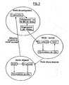
- the system includes a function called "role swapping", illustrated in FIG. figure 1d .
- the headend was, by default, that of the speakers which received the signals to be broadcast from the external device, the other speakers being all so-called "connected" speakers. But it must be possible to use another source which, given its position, will not establish direct radio contact with the headend, for example a source S 'too far from the speaker R to transmit audio data. It may also be data coming from a speaker, other than the head speaker, provided with an input jack connectable by a cable to a source of audio signals, usually analog (this point will be explained more in detail with reference to Figures 3 to 7 ).
- the source S ' is within radio range of one of the connected speakers of the system, for example the speaker L' in the example of the figure 1d .
- the connected speaker sends it to the headend R a "role swap request".
- This request is received and processed by the head speaker which will then temporarily define a new routing scheme so as to broadcast audio signals from the speaker L ', instead of from the speaker R. It will be noted that this modification of the routing scheme is done without changing the basic definition of the distribution graph; only the orientation of the different branches is possibly modified, corresponding to a modification of the origin and destination addresses in the routing scheme.
- the enclosure L ' will be "host” (that is to say server, in the sense of a client / server relationship), temporarily becoming head of the network, the enclosure R receiving the data (that is to say being a client, in the sense of a client / server relationship), becoming provisionally an enclosure attached.
- the processing of the role swap requests may possibly be combined with priority rules between sources, for example, the sound from a wireless phone being prioritized over the sound from a television, etc.
- This role swapping is temporary, the return to the initial state being triggered by an algorithm detecting the absence of audio signals delivered by the source S '. The network then returns to the "pending" state in its original configuration.
- a “degraded” mode in addition to the "normal" mode, there is provided a “degraded” mode in which the system is automatically placed when a connection between two speakers is lost, that is to say when the one of the neighbors of the routing scheme can no longer be recognized.
- Switching to degraded mode can occur at any time since, as mentioned above, the radio link between the speakers is a permanent link, even when no audio signal is reproduced and the system appears in standby to the user (it is actually in the state "pending" state where the various speakers continue to exchange signals with each other).
- “degraded” mode the system remains functional, but with lower performance, for example it operates in mono in the case of a stereo system, or with removal of the surround channels, etc.
- the degraded mode includes the same active states - pending - role swapping as in normal mode, with similar transitions.
- the system continues in the background to detect the loss of a speaker or the appearance of a speaker not attached to the network (speaker mode "new"). In this case, all the speakers return to the same "new" mode and the system re-runs a configuration procedure.
- This reconfiguration consists in making a reallocation of the head enclosure, especially if one of the criteria that had allowed the initial allocation has been modified: moving or disconnecting a speaker, substituting a defective speaker by another speaker , disruption of the transmission due to a change in the environment, ... Then the system is able to dynamically reconfigure the network, the head speaker may be possibly - but not necessarily - the same speaker as before.
- an algorithm is provided limiting the number of restarts. and / or executing the reconfiguration only after a predetermined delay.
- the algorithm can provide to permanently put it away from the network during the next phase of defining the routing scheme.
- This system comprises two enclosures 10 and 10 'interconnected by a wireless link 14.
- This system can be coupled to various peripherals, for example a digital player 16 provided with a Bluetooth module (internal or external) transmitting to the system a audio stream according to an A2DP profile, or a laptop 18 similarly sending audio data to the system.
- the peripherals can also be control devices, for example a remote control 20 sending to the system control signals according to an AVRCP profile.
- the device can also be a device capable of sending both audio signals and commands, for example a mobile phone / Bluetooth digital music player whose different keys of the keyboard can be used to control the system of the invention (selection of sources, volume, balance, ).
- the system can also be connected to traditional elements such as FM tuner , CD / DVD player / recorder, TV, etc. by a wired connection by means of plugs 26 connected to corresponding input jacks provided on the enclosure 10.
- the figure 4 shows the general external appearance of the enclosure 10, seen from the front.
- This speaker is for example a two-way speaker, with a speaker 34 of low / medium and an acute speaker 36, possibly concealed by a decorative grille 38.
- the enclosure is also provided with a block of control 40, with a light indicator 42 to signal the operation by changes in color and / or speed of blinking, and three control buttons, with two keys "+” and "-” 44 and 46 decrease or decrease Increasing the overall volume, and possibly a 48 "Reset” key to reset the system.
- the enclosure also includes antenna 50 for wireless transmission, which may be left visible in a transparent region of the enclosure.
- the figure 5 illustrates, in the form of functional blocks, the various hardware components of the enclosure 10.
- the enclosure also includes input jacks 52, arranged on the side or rear, for the connection of a type of CD or DVD player, TV, etc.. by a wired connection, and a mains unit 54 to be connected to a power outlet for the supply of the active speaker.
- the assembly is structured around a central control unit (MCU) 56, associated with a memory 58, comprising a microcontroller circuit and a digital signal processor.
- the central unit 56 is interfaced to a Bluetooth module 60, connected to the antenna 50, via a UART link 62.
- This Bluetooth module serves to establish links with all the other speakers of the system, as well as with source devices. Audio and / or remote control, in accordance with the specifications of the Bluetooth interface which provide, inter alia, the possibility of sending commands and data files, including audio data files in the form of a streaming stream. a remote device.
- the presence of a Bluetooth object within the range of the module is always according to these specifications; detected fully automatically without the user having to do anything to activate the link between object and Bluetooth module , link that becomes operational simply because of the entry of the device in the field of action of the circuit - and, in this case, provided of course that the Bluetooth object is a device that has a compatible profile, that is to say an A2DP profile and / or AVRCP. This detection is operated permanently by the module 60, in the background.
- the central unit 56 is also connected to the control block 40 (push-buttons 44, 46 and 48 and indicator light 42) by a GPIO link 64.
- the output converter 66 drives amplifiers 72, 74 outputly connected to the respective loudspeakers 34, 36.
- the input converter 68 is connected to the terminals 52 via a line input circuit 76, for digitizing the analog signals received on the input terminals 52.
- the amplifiers 72 and 74 are specific to each of the loudspeakers, that is to say that there are as many amplifiers as loudspeakers, with an input matching filter associated high-pass / pass below, preferably digital filtering performed in the stage 66, before conversion.
- the digital filtering can indeed be advantageously realized by software, so very economically without resorting to specific hardware components, without risk of degrading the sound quality by interposition of an analog filter, and with the possibility of equalizing and adapting the response curve of each channel depending on the speaker.
- the cutoff frequency is for example chosen at 3 kHz, the amplifier 72 reproducing the band 20 Hz-3 kHz and the amplifier 74 the band 3 kHz-20 kHz.
- the audio stream is processed according to the block diagram of the figure 6 Which illustrates the various software modules used for streaming of the audio stream (streaming).
- the application module 80 which interfaces with the user is interfaced to a network management module 82, to a Bluetooth transmit / receive module 84 , and to audio signal processing modules 86 to 94.
- the module 86 is an audio codec module, for decoding the stream received by the module 84, and in particular the separation of the various channels.
- multichannel audio stream right and left channels, front and back channels, etc. as well as the management of service information possibly encapsulated in the audio stream.
- the module 88 makes it possible to apply to the signal a suitable digital equalization, in particular to take account of the particular response curve of the speakers of the loudspeaker.
- the module 90 is a digital filter for separating the two channels, bass / mid and treble, to be reproduced by the respective loudspeakers of the enclosure.
- the data to be reproduced is applied to an output buffer 92 and then to the digital to analog converter 94 before being directed to the respective amplifiers and loudspeakers.
- the figure 7 represents, in the form of a block diagram, the various elements of the enclosure 10 concerned with the reproduction of the audio stream.
- a line input module 102 receives signals from a device connected by a conventional wired connection, delivering a signal applied to the analog / digital converter 104.
- the other sources communicate by a wireless link with a Bluetooth stack 106 feeding a Audio decoder 108.
- Block 110 provides channel separation, right and left in the case of a stereo set with two speakers.
- the right channel which will be reproduced by another speaker, is coded by the block 112 and then transmitted to the other speaker via the Bluetooth stack 114.
- the left channel, intended to be reproduced by the speaker 10 is subjected to a treatment equalizer 116, and possibly a mixture of the two right and left channels when the system operates in degraded mode (that is to say when the communication with the right speaker is not, or not yet possible) .
- Two digital filters 120, 122 separate the bands to be reproduced by the respective loudspeakers 34, 36 via the amplifiers 72, 74.
- Such a speaker can be used in particular for satellite speakers, which are certain that they will never be used as network head speakers to communicate with an external device. We can therefore save the audio coding circuits and various algorithms configuration and network management.
- the received signals are applied, via a Bluetooth stack 124, to the stage 126 which provides a reverse decoding of the one operated by the stage 112 of the head enclosure of the network. If the right / left channels have not been separated by the head enclosure, this separation is effected by a block 128.
- the stages 130, 132 and 134 of equalization and filtering are identical to the corresponding stages 116, 120 and 122 of the enclosure 10.
Landscapes
- Engineering & Computer Science (AREA)
- Databases & Information Systems (AREA)
- Computer Networks & Wireless Communication (AREA)
- Signal Processing (AREA)
- Circuit For Audible Band Transducer (AREA)
- Input Circuits Of Receivers And Coupling Of Receivers And Audio Equipment (AREA)
- Mobile Radio Communication Systems (AREA)
Abstract
Description
L'invention concerne un système de distribution de signaux audio entre une pluralité d'enceintes actives, permettant de restituer ces signaux sur les diverses enceintes respectives.The invention relates to a system for distributing audio signals between a plurality of active speakers, making it possible to reproduce these signals on the various respective speakers.
Les matériels audio de nouvelle génération intègrent une part de plus en plus importante de circuits numériques, destinés au traitement et à la transmission des signaux audio.Next-generation audio equipment includes a growing share of digital circuits for processing and transmitting audio signals.
La numérisation rend notamment possible une transmission par ondes radio, sans perte de qualité, des signaux audio entre les divers éléments instituant la chaîne de reproduction audio. La transmission sans fil est d'autant plus avantageuse que le nombre des canaux à reproduire est important : on assiste en effet à une multiplication du nombre des canaux, aussi bien pour les installations de pure reproduction audio (par exemple avec la technologie SACD de reproduction audio à haute définition) que pour les installations de type "cinéma à la maison". Généralement, ces installations prévoient une configuration sonore de type "5.1", c'est-à-dire avec un canal avant central, deux canaux avant latéraux (gauche et droit), deux satellites arrière (gauche et droit), ainsi qu'un caisson de basses. Le nombre de canaux peut même être augmenté jusqu'à une configuration "7.1", avec deux canaux d'ambiance ("surround") latéraux supplémentaires. De multiples configurations intermédiaires peuvent également être envisagées, depuis une simple configuration mono ou stéréo à une ou deux enceintes, jusqu'à des configurations incluant de nombreuses enceintes satellites et d'ambiance.Digitization makes it possible in particular to transmit radio waves, without loss of quality, audio signals between the various elements establishing the audio reproduction chain. Wireless transmission is all the more advantageous as the number of channels to be reproduced is important: there is indeed a multiplication of the number of channels, as well as for pure audio reproduction installations (for example with SACD reproduction technology). high definition audio) only for "home theater" installations. Generally, these installations provide a sound configuration of "5.1" type, that is to say with a central front channel, two front lateral channels (left and right), two rear satellites (left and right), as well as a subwoofer. The number of channels can even be increased to a "7.1" configuration, with two additional side surround channels. Multiple intermediate configurations can also be envisaged, from a simple mono or stereo configuration to one or two speakers, to configurations including many satellite and surround speakers.
Une problématique comparable se présente dans les installations de sonorisation professionnelle pour les lieux publics, magasins, chambres d'hôtel, etc. qui peuvent comprendre plusieurs dizaines, voire même plus, d'enceintes acoustiques, recevant de la musique ou autres signaux audio depuis une tête de réseau centrale. Il peut être en particulier souhaitable de diffuser des signaux de façon sélective vers tel ou tel groupe d'enceintes, et non vers d'autres, ou encore de pouvoir déplacer aisément les enceintes, par exemple dans le cas des installations temporaires mises en place au cours de spectacles, salons, etc.A similar problem occurs in professional sound systems for public places, shops, hotel rooms, etc. which may include dozens, or even more, of loudspeakers, receiving music or other audio signals from a central headend. In particular, it may be desirable to broadcast signals selectively to one or another group of speakers, and not to others, or to be able to easily move the speakers, for example in the case of temporary installations set up at the time. shows, shows, etc.
Pour éviter la multiplication des câbles de liaison entre la source de signaux et les enceintes, il a été proposé des systèmes de transmission sans fil vers les différentes enceintes du système, qui sont alors des enceintes dites "actives", c'est-à-dire incorporant un ou plusieurs amplificateurs basse fréquence associés au haut-parleur (ou au système de haut-parleurs) de l'enceinte. Ces enceintes actives ne requièrent en entrée qu'un signal de bas niveau, qui peut être transmis par des moyens sans fil, radio ou infrarouge, depuis un émetteur relié à la source de signal. Avec une telle enceinte active combinée à une transmission sans fil, la seule contrainte est le branchement de l'alimentation de l'enceinte à une prise de courant, ce qui laisse une très grande latitude pour le positionnement des différentes enceintes du système (même si elle ne sont qu'au nombre de deux, comme dans le cas d'un simple ensemble stéréo), positionnement dont on sait l'importance pour aboutir à une reproduction satisfaisante de l'environnement musical et des effets sonores éventuels. De nombreuses techniques ont été proposées pour réaliser la transmission sans fil de signaux audio, par exemple au moyen d'un boîtier émetteur indépendant relié à une source audio, ou à la sortie "ligne" d'une chaîne traditionnelle, boîtier qui, par transmission radio analogique ou numérique, envoie le signal produit par la source ou la chaîne vers des enceintes actives distantes. Ce boîtier émetteur peut être incorporé à la chaîne, l'ensemble audio se présentant alors sous forme d'un bloc intégré et de n enceintes actives. Cette chaîne, c'est-à-dire l'ensemble des éléments du système de reproduction audio à l'exception des enceintes (actives ou non), peut être composée de plusieurs éléments distants reliés entre eux par des moyens appropriés, filaires ou sans fil, ou intégrés dans une même unité assurant par des commutations appropriées les différentes fonctions (radio, CD, cassette, etc.)To avoid multiplication of the connection cables between the signal source and the speakers, wireless transmission systems have been proposed to the various speakers of the system, which are then so-called "active" speakers, that is to say ie incorporating one or more low frequency amplifiers associated with the loudspeaker (or loudspeaker system) of the enclosure. These active speakers require as input only a low level signal, which can be transmitted by wireless, radio or infrared means, from a transmitter connected to the signal source. With such an active speaker combined with a wireless transmission, the only constraint is the connection of the power supply of the speaker to a power outlet, which leaves a very wide latitude for the positioning of the various speakers of the system (even if there are only two of them, as in the case of a simple stereo set), a positioning whose importance is known to lead to a satisfactory reproduction of the musical environment and possible sound effects. Numerous techniques have been proposed for carrying out the wireless transmission of audio signals, for example by means of an independent transmitter box connected to an audio source, or to the "line" output of a conventional channel, which, by transmission, analog or digital radio, sends the signal produced by the source or channel to remote active speakers. This transmitter box can be incorporated in the chain, the audio unit then being in the form of an integrated block and n active speakers. This chain, that is to say all the elements of the audio reproduction system with the exception of the speakers (active or otherwise), may be composed of several distant elements interconnected by appropriate means, wired or without wire, or integrated in the same unit ensuring by appropriate switching the various functions (radio, CD, cassette, etc.)
Il est également souhaitable de disposer d'une transmission sans fil non seulement en aval, c'est-à-dire de la chaîne aux enceintes, mais également en amont, c'est-à-dire pour relier des sources distantes telles que baladeur ou lecteur de musique numérique (MP3, AAC, ...), assistant numérique personnel ou encore un ordinateur pourvu de moyens de transmission radio intégrés ou ajoutés sous forme d'un adaptateur connecté à un port externe de l'ordinateur.It is also desirable to have a wireless transmission not only downstream, that is to say from the string to the speakers, but also upstream, that is to say to connect remote sources such as walkman or digital music player (MP3, AAC, etc.), personal digital assistant or a computer provided with radio transmission means integrated or added as an adapter connected to an external port of the computer.
Les divers systèmes proposés jusqu'à présent ne résolvent que partiellement le problème de la suppression des liaisons filaires dans un ensemble de reproduction audio.The various systems proposed so far only partially solve the problem of removing wired links in a set of audio reproduction.
Ces systèmes connus sont généralement conçus autour d'un boîtier émetteur couplé à des enceintes actives spécialement adaptées, avec une technologie privative propre au constructeur, conduisant à un système fermé, peu ou pas évolutif.These known systems are generally designed around a transmitter box coupled to specially adapted active speakers, with a private technology specific to the manufacturer, leading to a closed system, little or no evolution.
Pour les liaisons des diverses sources, des adaptateurs d'émission et de réception sont requis, avec des contraintes de branchement, de liaison, d'alimentation ..., qui peuvent rebuter les utilisateurs peu motivés par ce type de technologie.For the links of the various sources, transmit and receive adapters are required, with constraints of connection, connection, power supply ..., which can put off the users little motivated by this type of technology.
Enfin, l'ergonomie de ces appareils est en général assez médiocre et nécessite une implication de l'utilisateur telle que celui-ci, en pratique, n'utilise que très peu la multitude de fonctions qui lui sont offertes par le système.Finally, the ergonomics of these devices is generally quite poor and requires the involvement of the user as it, in practice, uses very little of the multitude of functions that are offered by the system.
Le
La proposition de cette antériorité, si elle permet de pallier un certain nombre des inconvénients exposés plus haut grâce à la mise en oeuvre de liaisons sans fil, présente cependant une souplesse d'utilisation limitée, notamment par le fait que le dispositif maître doive être défini à l'avance, par construction ou par l'utilisateur. De ce fait, le réseau n'est pas nécessairement configuré de façon optimale, compte tenu des conditions de propagation en particulier. Il n'est pas non plus modifiable dynamiquement en fonction des circonstances : notamment un débranchement ou une panne du dispositif maître entraîne un arrêt général du système.The proposal of this prior art, while it makes it possible to overcome a number of the disadvantages set out above by virtue of the implementation of wireless links, however, has a limited flexibility of use, in particular by the fact that the master device must be defined in advance, by construction or by the user. As a result, the network is not necessarily optimally configured, especially given the propagation conditions. It is also not dynamically modifiable depending on the circumstances: in particular a disconnection or failure of the master device causes a general shutdown of the system.
Le
L'un des buts de l'invention est de proposer un système de distribution d'un signal audio multicanal universel permettant de pallier les difficultés évoquées ci-dessus grâce notamment aux caractéristiques suivantes:
- un minimum d'éléments matériels apparents, les différents circuits et organes fonctionnels étant incorporés aux enceintes et n'étant pas visibles ni accessibles à l'utilisateur ;
- pas de branchement nécessaire, si ce n'est la prise de courant pour alimenter l'enceinte ;
- ergonomie simplifiée à la mise en route, le système étant "Plug-and-Play" c'est-à-dire que l'utilisateur n'aura qu'à se soucier de placer les enceintes et de brancher les prises de courant, le système se configurant de lui-même de façon totalement automatique et transparente pour l'utilisateur;
- définition par le système lui-même de la topologie du réseau selon une configuration optimale, et ceci de façon entièrement systématique et automatique ;
- possibilité de définir et hiérarchiser le réseau à partir de l'une quelconque des enceintes du système, celles-ci étant initialement toutes indifférenciées du point de vue de la topologie du réseau ;
- possibilité d'auto-reconfiguration dynamique du réseau sans interruption du fonctionnement, par exemple en cas de modification des conditions de transmission du signal radio ou de débranchement d'une ou plusieurs enceintes.
- ergonomie simplifiée, grâce à une automatisation poussée du fonctionnement et une réduction au strict minimum des boutons-poussoirs et autres commandes ;
- caractère évolutif et auto-adaptatif, quel que soit le nombre d'enceintes actives (deux, quatre, cinq, "5.1", "7.1",...) : par exemple, si un utilisateur dispose déjà d'une configuration stéréo (deux enceintes), il lui suffira d'acquérir et de brancher deux satellites et un caisson de basses pour transformer immédiatement son ensemble en système "4.1 ", sans intervention sur les enceintes existantes, le système se reconfigurant de façon entièrement automatique dès la mise sous tension des nouvelles enceintes ;
- utilisation possible avec toute source munie de moyens de transmission sans fil appropriés ;
- possibilité de pilotage à distance, non seulement par une télécommande spécifique, mais également par un quelconque appareil pourvu de touches et de moyens de transmission sans fil appropriés, par exemple au moyen d'un téléphone portable.
- a minimum of apparent hardware elements, the various circuits and functional organs being incorporated into the speakers and not being visible or accessible to the user;
- no connection necessary, except the socket to power the enclosure;
- ergonomics simplified at startup, the system is "Plug and Play" that is to say that the user will only have to worry about placing the speakers and plug the power, the self-configuring system in a fully automatic and transparent way for the user;
- definition by the system itself of the topology of the network according to an optimal configuration, and this in a completely systematic and automatic way;
- possibility to define and hierarchize the network from any of the speakers of the system, these being initially all undifferentiated from the point of view of the topology of the network;
- possibility of dynamic self-reconfiguration of the network without interruption of operation, for example in case of modification of the conditions of transmission of the radio signal or disconnection of one or more speakers.
- Simplified ergonomics, thanks to extensive automation of operation and a reduction of push buttons and other controls to a minimum;
- scalable and auto-adaptive character, regardless of the number of active speakers (two, four, five, "5.1", "7.1", ...): for example, if a user already has a stereo configuration ( two speakers), it will be enough to acquire and connect two satellites and a subwoofer to immediately transform its entire system "4.1", without intervention on existing speakers, the system is reconfigured fully automatically from the start voltage of the new speakers;
- possible use with any source equipped with appropriate wireless transmission means;
- possibility of remote control, not only by a specific remote control, but also by any device provided with keys and appropriate wireless transmission means, for example by means of a mobile phone.
Le système de l'invention est du type divulgué par la revendication 1. Les sous-revendications visent des modes de réalisation préférentiels avantageux.The system of the invention is of the type disclosed by claim 1. The subclaims are advantageous preferred embodiments.
On va maintenant décrire un exemple de mise en oeuvre du dispositif de l'invention, en référence aux dessins annexés où les mêmes références numériques désignent d'une figure à l'autre des éléments identiques ou fonctionnelle ment semblables.
- La
figure 1 illustre les différentes étapes (a) à (d) de la mise en place et de la configuration du réseau d'enceintes selon l'invention. - La
figure 2 illustre de façon schématique les divers modes de fonctionnement du système de l'invention, avec les transitions d'états et de modes possibles. - La
figure 3 est une vue schématique d'un exemple de système de l'invention et des différents éléments qui peuvent y être reliés. - La
figure 4 est une vue de face d'une des enceintes actives du système selon l'invention. - La
figure 5 est un schéma fonctionnel par blocs de l'enceinte active du système de l'invention. - La
figure 6 illustre les divers modules logiciels impliqués dans la restitution du signal audio. - La
figure 7 est un schéma par blocs fonctionnels des différents éléments de l'enceinte concernés par la restitution audio. - Les
figures 8 et 9 sont homologues desfigures 5 et7 , pour une enceinte simplifiée utilisable dans le système de l'invention.
- The
figure 1 illustrates the different steps (a) to (d) of the establishment and configuration of the speaker array according to the invention. - The
figure 2 schematically illustrates the various modes of operation of the system of the invention, with the transitions of states and possible modes. - The
figure 3 is a schematic view of an exemplary system of the invention and the various elements that can be connected thereto. - The
figure 4 is a front view of one of the active speakers of the system according to the invention. - The
figure 5 is a block diagram of the active enclosure of the system of the invention. - The
figure 6 illustrates the various software modules involved in the rendering of the audio signal. - The
figure 7 is a functional block diagram of the different elements of the enclosure concerned by the audio reproduction. - The
Figures 8 and 9 are counterpartsfigures 5 and7 , for a simplified speaker usable in the system of the invention.
On va d'abord décrire, en référence à la
On prendra l'exemple d'un système comprenant une configuration de type "7.1" plus une paire d'enceintes stéréo supplémentaires, par exemple des enceintes installées dans une autre pièce.An example of a system comprising a "7.1" type configuration plus a pair of additional stereo speakers, for example speakers installed in another room, will be used.
Les enseignements de l'invention sont cependant applicables, par simple extrapolation, à des configurations comportant un nombre d'enceintes moindre (par exemple une configuration stéréo de base à deux enceintes, droite et gauche, qui est la configuration la plus simple), aussi bien qu'à des configurations encore plus complexes, par exemple dans des applications de sonorisation professionnelle. Au départ, l'utilisateur place les enceintes à l'endroit voulu, en respectant le positionnement respectif des différentes sources acoustiques. Une configuration "7.1" comprend ainsi des enceintes de canal avant central C, de canaux avant latéraux gauche et droit L et R, de canaux d'ambiance latéraux L1 et R1, de satellites arrière L2 et R2 et un caisson de basses W. Dans l'exemple illustré on supposera que l'installation comprend également, par exemple dans une pièce voisine, une paire d'enceintes droite et gauche L'et R'.The teachings of the invention are however applicable, by simple extrapolation, to configurations having a smaller number of speakers (for example a basic stereo configuration with two speakers, right and left, which is the simplest configuration), also although to even more complex configurations, for example in professional sound applications. Initially, the user places the speakers at the desired location, respecting the respective positioning of the different acoustic sources. A configuration "7.1" thus comprises central front channel speakers C, front left and right front channels L and R, side surround channels L1 and R1, rear satellites L2 and R2 and a subwoofer W. In the illustrated example it will be assumed that the installation also includes, for example in a neighboring room, a pair of right and left speakers L and R '.
Chacune des enceintes est une enceinte "active", c'est-à-dire comprenant non seulement un ou plusieurs haut-parleurs, mais également un amplificateur intégré. Chaque enceinte comprend également une interface radio lui permettant de communiquer avec l'extérieur pour recevoir et émettre des signaux, de la manière que l'on décrira plus en détail par la suite, en référence aux
Le type de liaison sans fil radio bidirectionnelle choisi est très avantageusement une liaison de type Bluetooth (marque déposée du Bluetooth SIG, Inc.).The type of wireless two-way radio link chosen is very advantageously a Bluetooth type connection (registered trademark of Bluetooth SIG, Inc.).
En effet, les spécifications Bluetooth offrent la possibilité de piloter à distance par une liaison sans fil bidirectionnelle un dispositif éloigné. En pratique, il s'agit le plus souvent d'un téléphone portable ou d'un périphérique informatique, mais les spécifications Bluetooth ne se limitent pas à ce type d'appareil et incluent notamment des profils compatibles avec la transmission de flux audio multicanal codés de haute qualité (profil A2DP : Advanced Audio Distribution Profile), ainsi que des profils assurant l'interopérabilité des appareils Bluetooth avec des fonctions de commande audio et vidéo (profil AVRCP : Audio Video Remote Control Profile). Indeed, the Bluetooth specifications offer the possibility of remote control by a bidirectional wireless link a remote device. In practice, it is most often a mobile phone or a computer peripheral, but Bluetooth specifications are not limited to this type of device and include profiles compatible with the transmission of multichannel audio streams coded high quality ( A2DP profile : Advanced Audio Distribution Profile ) , as well as profiles ensuring interoperability Bluetooth devices with audio and video control functions (AVRCP Profile: Audio Video Remote Control Profile ) .
Le choix de la technologie Bluetooth est particulièrement avantageuse compte tenu de son caractère universel et évolutif, de l'existence de nombreuses fonctionnalités, ainsi que de nombreux composants, au surplus peu coûteux, spécialement conçus pour sa mise en oeuvre. Ce choix n'est cependant aucunement limitatif, et l'invention peut être mise en oeuvre au moyen d'autres techniques de transmission sans fil, dès lors que ces techniques offrent un débit de données suffisant pour permettre la transmission de signaux audio numériques de haute qualité : tel est par exemple le cas de la norme IEEE 802.11 (ISO/IEC 8802-11) dite "WiFi".The choice of Bluetooth technology is particularly advantageous given its universal and scalable, the existence of many features, as well as many components, moreover inexpensive, especially designed for its implementation. This choice is however in no way limitative, and the invention can be implemented by means of other wireless transmission techniques, provided that these techniques offer a data rate sufficient to allow the transmission of high-level digital audio signals. quality: this is for example the case of the standard IEEE 802.11 (ISO / IEC 8802-11) called "WiFi".
On notera que la technologie Bluetooth est utilisée dans le cadre de l'invention de manière quelque peu différente de sa finalité originelle - mais toutefois sans modification des protocoles, de manière à rester parfaitement compatible avec les prescriptions des spécifications Bluetooth. En effet, la technologie Bluetooth a été conçue pour permettre une transmission ponctuelle de données sur une durée limitée, par exemple la durée d'une conversation téléphonique, ou la durée de l'envoi d'un fichier à une imprimante, mais il n'a pas jusqu'à présent été envisagé de l'utiliser pour établir une liaison permanente dans un système, comme dans le cas de l'invention, où l'on verra que la liaison entre les différentes enceintes perdure tant que les enceintes ne sont pas désalimentées, c'est-à-dire débranchées : lorsque le système est en veille, c'est-à-dire apparemment inactif pour un utilisateur, les liaisons sans fil entre les enceintes restent actives, quoique avec un trafic d'informations réduit, de manière à permettre le maintien de la configuration du réseau et la détection à tout moment d'un signal externe par le réseau.Note that Bluetooth technology is used in the context of the invention somewhat different from its original purpose - but without modification of the protocols, so as to remain fully compatible with the requirements of the Bluetooth specifications . Indeed, Bluetooth technology has been designed to allow a one-time transmission of data over a limited time, for example the duration of a telephone conversation, or the duration of sending a file to a printer, but it does not has not been considered until now to use it to establish a permanent link in a system, as in the case of the invention, where we will see that the connection between the various speakers continues as long as the speakers are not unpowered, ie disconnected: when the system is idle, ie apparently inactive for a user, the wireless links between the speakers remain active, albeit with reduced information traffic, so as to allow the maintenance of the network configuration and the detection at any time of an external signal by the network.
Une autre originalité de l'invention consiste à mettre à profit les possibilités particulières offertes par les spécifications Bluetooth de réaliser non seulement des liaisons point-à-point entre deux éléments, mais également d'établir et de gérer des réseaux plus ou moins complexes constitués entre un certain nombre de ces éléments.Another originality of the invention is to take advantage of the particular possibilities offered by Bluetooth specifications to achieve not only point-to-point links between two elements, but also to establish and manage more or less complex networks constituted between a number of these elements.
Un premier type de réseau est le "piconet", ou micro-réseau, qui se crée de manière automatique lorsque plusieurs éléments compatibles Bluetooth se trouvent dans un même rayon. Le piconet .suit une topologie en étoile, avec un maître et plusieurs esclaves. Les esclaves peuvent être soit "actifs", c'est-à-dire en communication avec le maître, soit "parqués", c'est-à-dire mis provisoirement en sommeil, avec possibilité pour le maître de les réveiller pour les rendre actifs. Les communications sont directes entre le maître et les esclaves. Les esclaves ne peuvent pas communiquer entre eux.A first type of network is the "piconet", or micro-network, which is created automatically when several Bluetooth compatible elements are in the same radius. The piconet .suit a topology in star, with a master and several slaves. Slaves can be either "active", that is to say in communication with the master, or "parked", that is to say put temporarily dormant, with possibility for the master to wake them to make them assets. Communications are direct between the master and the slaves. Slaves can not communicate with each other.
Un autre type de réseau selon les spécifications Bluetooth est le "scatter-net", ou réseau éclaté, qui est un réseau formé de plusieurs piconets reliés entre eux par un esclave commun, qui possède plusieurs maîtres. Ceci permet, géographiquement, d'augmenter l'étendue du réseau par recouvrement partiel et chaînage de plusieurs piconets.Another type of network according to the Bluetooth specifications is the "scatter-net" or scatternet, which is a network formed of several piconets interconnected by a common slave that has multiple masters. This allows, geographically, to increase the extent of the network by partial recovery and chaining of several piconets.
On notera à cet égard que l'invention sera décrite ici dans le cadre d'une transmission mettant en oeuvre une technologie Bluetooth mais que, comme indiqué plus haut, ce choix n'est aucunement limitatif et que d'autres technologies permettant de constituer un réseau local sans fil WLAN sont utilisables aussi bien. En particulier, la terminologie "maître/ esclave", qui est celle utilisée par les spécifications Bluetooth, ne doit être aucunement considérée comme limitative, et doit être considérée comme équivalente à toute autre terminologie de description de topologie de réseau telle que "hôte/périphérique", "hôte/dispositif", ou "client/serveur". L'invention propose, à partir d'un ensemble d'enceintes indépendantes simplement placées dans un local, comme illustré sur la
On va expliquer comment cette configuration peut être réalisée de manière entièrement automatique, et de plus adaptative, c'est-à-dire que l'organisation du réseau pourra être modifiée automatiquement en cas, par exemple, d'ajout ou de retrait d'une enceinte, et ce façon entièrement transparente pour l'utilisateur.We will explain how this configuration can be performed fully automatically, and more adaptively, that is to say that the organization of the network can be automatically modified in case, for example, adding or removing a speaker, and this way completely transparent to the user.
À l'origine - et il s'agit là d'une caractéristique particulièrement originale procurée par l'invention - toutes les enceintes sont indépendantes et sur le même plan du point de vue de la topologie du réseau à configurer, c'est-à-dire que l'enceinte qui sera maîtresse (hôte) du réseau hiérarchisé n'est pas nécessairement déterminée a priori et pourra être, en fonction des circonstances, l'une quelconque des enceintes du système.Originally - and this is a particularly original feature provided by the invention - all speakers are independent and on the same plane from the point of view of the topology of the network to be configured, that is to say ie the speaker that will be master (host) of the hierarchical network is not necessarily determined a priori and may be, depending on the circumstances, any of the speakers of the system.
Les enceintes sont cependant "différenciées", non pas en ce qui concerne la topologie de connexion (qui sera définie par le réseau lorsque celui-ci sera configuré) mais selon leur position physique, fonction du rôle acoustique qu'elles auront à jouer: par exemple "enceinte droite", "enceinte gauche", "caisson de basses", "satellite arrière droit", satellite arrière gauche", etc.The speakers are however "differentiated", not as regards the connection topology (which will be defined by the network when it is configured) but according to their physical position, depending on the acoustic role they will have to play: by example "right speaker", "left speaker", "subwoofer", "right rear satellite", left rear satellite ", etc.
La différenciation de l'enceinte peut être opérée de plusieurs manières :
- de façon matérielle, une fois pour toutes : l'enceinte comporte alors une étiquette permettant de reconnaître le rôle qu'elle doit jouer dans l'installation,
- de façon matérielle et modifiable, par exemple par un commutateur interne ou placé en face arrière,
- par logiciel, a posteriori après configuration du réseau, par envoi sur celui-ci de messages spécifiques sur requête de l'utilisateur,
- de façon entièrement automatique, en prévoyant, a priori ou a posteriori des moyens de localisation dans l'espace des positions relatives des différentes enceintes, de manière à les différencier en fonction de leur position physique relative.
- in a material way, once and for all: the enclosure then has a label allowing to recognize the role that it must play in the installation,
- in a material and modifiable manner, for example by an internal switch or placed on the rear face,
- by software, a posteriori after configuration of the network, by sending thereon specific messages on request of the user,
- in a fully automatic manner, by providing, a priori or a posteriori location means in the space of the relative positions of the different speakers, so as to differentiate according to their relative physical position.
Avant la configuration, toutes les enceintes sont en un mode dit "nouveau", c'est-à-dire qu'elles sont encore indépendantes, et vont chercher à se configurer en réseau.Before configuration, all the speakers are in a so-called "new" mode, that is to say that they are still independent, and will seek to configure themselves in a network.
La première phase du protocole de configuration du réseau est illustrée
Elle est exécutée de manière autonome par chacune des enceintes, et conformément aux protocoles Bluetooth standard : chaque enceinte se configure en mode "découvrable" de manière à pouvoir être reconnue par les autres, et va rechercher toutes les enceintes situées dans son rayon d'action, c'est-à-dire avec lesquelles il lui est possible d'établir une communication sans fil satisfaisante. En effet, en raison de l'éloignement des éléments et de la portée volontairement limitée de la transmission Bluetooth, il peut se faire que certaines des enceintes ne soient pas visibles de toutes les autres enceintes, ou que la liaison soit d'une qualité trop faible, ce qui aurait pour effet d'introduire un nombre excessif d'erreurs de transmission conduisant à une répétition des données à transmettre et un retard trop important dans le flux audio reçu.It is performed autonomously by each speaker, and according to standard Bluetooth protocols: each speaker configures itself in "discoverable" mode so that it can be recognized by others, and will search for all speakers within its range. , that is with which it is possible for him to establish a satisfactory wireless communication. Indeed, because of the distance of the elements and the voluntarily limited range of the Bluetooth transmission , it can happen that some of the speakers are not visible from all the other speakers, or that the link is of a quality too much low, which would have the effect of introducing an excessive number of transmission leading to a repetition of the data to be transmitted and too much delay in the audio stream received.
À ce stade ou à un stade ultérieur, l'enceinte examine également si l'objet Bluetooth avec lequel elle a établi une liaison effective est bien un objet "compatible", c'est-à-dire une enceinte destinée à la constitution d'un système selon l'invention, et non un périphérique qui sera utilisé ultérieurement (source audio ou télécommande), ou encore un autre dispositif Bluetooth n'ayant aucun rapport fonctionnel avec le système de l'invention (imprimante, etc.). Cette vérification de compatibilité peut notamment se fonder sur un paramètre Bluetooth libre spécifiquement paramétré, par exemple le "Dedicated Inquiry Access Code". At this stage or at a later stage, the enclosure also examines whether the Bluetooth object with which it has established an effective link is a "compatible" object, ie an enclosure intended for the constitution of a system according to the invention, and not a device that will be used later (audio source or remote), or another Bluetooth device having no functional relationship with the system of the invention (printer, etc.). This compatibility check may in particular be based on a freely parameterized free Bluetooth parameter, for example the "Dedicated Inquiry Access Code".
Cette vérification peut en particulier mettre en oeuvre une authentification des enceintes entre elles, par exemple une authentification basée sur un algorithme à clef publique de type RSA ou analogue.This verification can in particular implement a speaker authentication between them, for example an authentication based on an RSA type public key algorithm or the like.
Cet algorithme est en lui-même bien connu, mais il est appliqué ici de manière originale.This algorithm is in itself well known, but it is applied here in an original way.
En effet, dans le cadre de la présente invention, deux enceintes doivent pouvoir s'authentifier :
- mutuellement,
- de manière sûre (ce que permet une clef publique),
- rapidement,
- sans intervention ni implication de l'utilisateur (à la différence d'un algorithme RSA utilisé de manière conventionnelle),
- de façon préalable (dans la mesure où, avant l'authentification, il n'est pas possible d'établir la liaison effective avec l'enceinte distante).
- mutually,
- in a safe way (which allows a public key),
- quickly,
- without intervention or user involvement (unlike an RSA algorithm conventionally used),
- as a precondition (since, before authentication, it is not possible to establish the effective connection with the remote speaker).
L'invention utilise la caractéristique selon laquelle le logiciel des enceintes est le même pour toutes les enceintes, et l'identité de ces logiciels fait que les clefs publiques et privées seront les mêmes pour chaque enceinte, donc connues de chacune d'entre elles.The invention uses the characteristic that the speaker software is the same for all speakers, and the identity of these software that the public and private keys will be the same for each speaker, so known to each of them.
A cet effet, chaque enceinte utilise une donnée d'identification prédéterminée, par exemple le "Friendly Name" ou l'"EIR Information" des spécifications Bluetooth ou l'identifiant SSID d'un réseau WLAN, et combine par un algorithme à clef publique de type RSA cette donnée aux données d'authentification pour produire une signature numérique. Cette signature est reçue par l'enceinte distante, qui la décode et la compare à sa propre donnée d'identification.For this purpose, each speaker uses a predetermined identification data, for example the "Friendly Name" or the " EIR Information" of the Bluetooth specifications or the SSID of a WLAN network, and combines with a public key algorithm RSA type this data to the authentication data to produce a digital signature. This signature is received by the remote speaker, which decodes it and compares it with its own identification data.
On notera que, dans la mesure où les clefs publique et privée sont les mêmes pour chaque enceinte (toutes utilisent le même logiciel) et donc connues de chaque enceinte, il n'y a pas besoin de procéder à un échange préalable de la clef publique avant l'authentification.Note that, since the public and private keys are the same for each speaker (all use the same software) and therefore known to each speaker, there is no need to carry out a prior exchange of the public key before authentication.
On notera également que le contrôle du "Dedicated Inquiry Access Code" mentionné plus haut constitue un premier niveau de filtrage qui permet de limiter l'impact des interrogations opérées sur les autres enceintes.Note also that the control of the "Dedicated Inquiry Access Code" mentioned above is a first level of filtering that limits the impact of queries made from the other speakers.
Par ailleurs, dans la mesure où chaque enceinte diffuse un message vers toutes les autres enceintes, cette procédure est également exécutée en sens inverse, depuis l'enceinte distante. L'authentification selon l'invention est ainsi une authentification mutuelle et symétrique entre les deux enceintes. Pour un nombre d'enceintes supérieur à deux, l'authentification est effectuée de la même façon entre tous les couples d'enceintes présentes.In addition, since each speaker broadcasts a message to all other speakers, this procedure is also performed in the opposite direction from the remote speaker. The authentication according to the invention is thus a mutual and symmetrical authentication between the two speakers. For a number of speakers greater than two, the authentication is performed in the same way between all the pairs of speakers present.
Sur la base des résultats de la recherche ainsi opérée, chaque enceinte établit une "table de proximité" où chacune des enceintes qui lui est visible est identifiée de manière univoque, par exemple par son adresse MAC (Media Access Control), qui est l'adresse Bluetooth dans le cas présent). Cette table comprend par exemple, pour chacune des enceintes trouvées, son adresse MAC, la version de son logiciel ainsi que sa "différenciation" au sens indiqué plus haut, c'est-à-dire la définition de son rôle spécifique (avant gauche, avant droite, caisson de basses, etc.).On the basis of the results of the search thus carried out, each speaker establishes a "proximity table" where each of the speakers which is visible to him is uniquely identified, for example by his MAC ( Media Access Control ) address , which is the Bluetooth address in this case). This table includes, for example, for each of the found speakers, its MAC address, the version of its software and its "differentiation" in the sense indicated above, that is to say the definition of its specific role (left front, front right, subwoofer, etc.).
La deuxième phase du protocole de configuration consiste à désigner, parmi toutes les enceintes qui ont été découvertes à la phase précédente, l'une d'entre elles qui constituera l'enceinte de tête du réseau, à partir de laquelle ce réseau sera hiérarchisé de manière à définir de façon univoque un chemin pour la diffusion des signaux audio.The second phase of the configuration protocol consists in designating, among all the loudspeakers that were discovered in the previous phase, one of them which will constitute the leading speaker of the network, from which this network will be hierarchical of to uniquely define a path for broadcasting audio signals.
Cette enceinte, ci-après désignée "enceinte de tête" aura également pour fonction de servir de "tête de pont" (pier) vers l'extérieur pour le réseau, c'est-à-dire de constituer un point d'accès, seul visible, pour tout périphérique formant source de signaux audio et/ou de commandes pour le réseau. Des exemples de ces périphériques seront décrits plus en détail plus bas en référence à la
En effet, un aspect important de l'invention est le fait que le système constitué des diverses enceintes du réseau se comporte comme un ensemble unique vis-à-vis des différents périphériques sans fil extérieurs qui peuvent lui être couplés, c'est-à-dire que, une fois le système configuré, les divers périphériques ne verront, fonctionnellement, qu'un seul dispositif compatible Bluetooth auquel chaque périphérique pourra se coupler sans qu'il lui soit nécessaire, notamment, de s'adapter à la topologie des différentes enceintes du système, et ceci même si la communication avec l'enceinte de tête n'est pas directe, mais se fait via une ou plusieurs autres enceintes (on exposera plus bas cet aspect de l'invention plus en détail).Indeed, an important aspect of the invention is the fact that the system consisting of the various speakers of the network behaves as a single set vis-à-vis the various external wireless devices that can be coupled to it, that is to say ie, once the system is configured, the various devices will functionally see only one Bluetooth- compatible device to which each device can couple without it being necessary, in particular, to adapt to the topology of different system speakers, and this even if the communication with the head speaker is not direct, but is via one or more other speakers (this aspect of the invention will be discussed in more detail below).
La désignation de l'enceinte de tête est opérée par un algorithme qui attribue une note en fonction de divers paramètres, par exemple le numéro de version de logiciel le plus récent, l'adresse MAC la plus élevée, etc. Cet algorithme est exécuté par chacune des enceintes, sur la base de sa table de proximité, en appliquant l'algorithme à chacune des enceintes répertoriées dans la table : elle se connecte alors à cette dernière, pour permettre l'échange de messages permettant d'évaluer le critère de l'enceinte interrogée par rapport à son propre critère. Ces messages échangés sont du type question/réponse tels que : "est-ce que tu as mieux ?", "j'ai mieux", "je n'ai pas mieux", "je suis l'enceinte de tête" : chaque enceinte cherche le "candidat" tête de réseau en appliquant l'algorithme à toutes les entrées de sa table de proximité, puis se connecte à ce candidat et, pour confirmer sa décision, lui envoie un message "est-ce que tu as mieux ?" (sous entendu : " ... que la note donnée par l'algorithme appliqué à ma table de proximité)". La réponse sera : "j'ai mieux", "je n'ai pas mieux", ou "je suis l'enceinte de tête". Puis l'enceinte qui pense avoir la meilleure note essaye de se connecter à toutes les autres enceintes, et ainsi, de proche en proche, jusqu'à trouver l'enceinte ayant la note la plus élevée, qui sera alors désignée comme enceinte de tête.Header designation is operated by an algorithm that assigns a rating based on various parameters, such as the latest software version number, the highest MAC address, and so on. This algorithm is executed by each of the speakers, based on its proximity table, by applying the algorithm to each of the speakers listed in the table: it then connects to the latter, to allow messages to be exchanged. evaluate the criterion of the speaker questioned in relation to his own criterion. These exchanged messages are of the question / answer type such as: "do you have better?", "I have better", "I do not have better", "I am the leading speaker": each Pregnant searches for the "candidate" head of network by applying the algorithm to all the entries of his proximity table, then connects to this candidate and, to confirm his decision, sends him a message "do you have better? " (understood: "... that the note given by the algorithm applied to my proximity table)". The answer will be: "I have better", "I have no better", or "I am the head speaker". Then the speaker who thinks he has the best note tries to connect to all the other speakers, and thus, step by step, until finding the loudspeaker with the highest note, which will then be designated as the head speaker .
De façon générale, le critère permettant de sélectionner l'enceinte de tête parmi toutes les enceintes peut être un critère unique ou une combinaison de plusieurs critères associés et éventuellement pondérés, parmi lesquels :
- le numéro d'adresse MAC ("Device Address" dans le cas particulier d'une communication en technologie Bluetooth),
- la possibilité d'établir une liaison directe de l'enceinte de tête à chacune des autres enceintes du réseau (absence de noeud caché),
- la recherche de la topologie la plus simple possible (en évitant par exemple la constitution de scattemets, si une topologie de piconets est possible et suffisante),
- le rôle acoustique de l'enceinte dans le réseau (par exemple une enceinte centrale ou un caisson de basse sera considéré comme a priori plus favorablement placé qu'un satellite arrière).
- the MAC address number (" Device Address " in the particular case of a communication in Bluetooth technology) ,
- the possibility of establishing a direct link from the head speaker to each of the other speakers of the network (no hidden node),
- the search for the simplest possible topology (avoiding for example the constitution of scattemets, if a topology of piconets is possible and sufficient),
- the acoustic role of the speaker in the network (for example a central speaker or a subwoofer will be considered a priori more favorably placed than a rear satellite).
On verra plus loin qu'il est possible de procéder si nécessaire à une reconfiguration dynamique du réseau, de façon transparente pour l'utilisateur, si l'un de ces critères venait à changer.We will see later that it is possible to proceed if necessary to a dynamic reconfiguration of the network, in a transparent manner for the user, if one of these criteria were to change.
L'échange des messages entre les diverses enceintes au cours de cette deuxième phase permet notamment, de proche en proche, de corriger d'éventuelles erreurs de sélection de l'enceinte de tête dues à une connaissance parcellaire du réseau (une enceinte ne voit pas nécessairement toutes les autres), ou à des lacunes lors de la détection.The exchange of messages between the various speakers during this second phase makes it possible, step by step, to correct any errors in the selection of the head speaker due to a fragmentary knowledge of the network (an enclosure does not see necessarily all others), or gaps in the detection.
Après un certain nombre d'itérations, cette deuxième phase aboutit ainsi à la désignation de l'enceinte de tête (pier), les autres enceintes étant alors toutes désignées comme "enceintes rattachées" (linked), c'est-à-dire des enceintes non autonomes, dépendantes de l'enceinte de tête et recevant de celle-ci les données audio à diffuser.After a certain number of iterations, this second phase thus leads to the designation of the head enclosure ( pier ) , the other enclosures then being all designated as "connected enclosures" ( linked ) , that is to say non-autonomous speakers, dependent on the head speaker and receiving from it the audio data to be broadcast.
La troisième phase du protocole de configuration est une phase d'organisation du réseau autour de l'enceinte de tête (pier networking), illustrée
Il s'agit de passer de la configuration de la
Pour cela, l'enceinte de tête commence par collecter les tables de proximité de toutes les autres enceintes. Chaque enceinte rattachée va envoyer sa table de proximité au "candidat" trouvé à l'étape précédente. Celui-ci l'envoie à son propre "candidat", et ainsi de suite jusqu'à atteindre l'enceinte de tête.For this, the head speaker begins by collecting the proximity tables of all other speakers. Each attached enclosure will send its proximity table to the "candidate" found in the previous step. This one sends it to its own "candidate", and so on until reaching the enclosure of head.
L'enceinte de tête explore alors toutes les tables de proximité collectées et construit un graphe de réseau, fonction des visibilités de chacune des enceintes. Un certain nombre de messages sont ainsi échangés entre les enceintes, en provenance ou à destination de l'enceinte de tête. Ceci permet à cette dernière de former une carte du réseau sous sa forme initiale, à partir des tables de visibilité de toutes les autres enceintes, et ce même si une enceinte ne voit pas toutes les autres. Ce réseau peut être de très grande étendue, par exemple dans des applications professionnelles pour sonoriser des lieux publics.The head enclosure then explores all the collected proximity tables and builds a network graph, according to the visibilities of each speaker. A certain number of messages are thus exchanged between the speakers, coming from or going to the head speaker. This allows the latter to form a network map in its original form, from the visibility tables of all other speakers, even if a speaker does not see all the others. This network can be very large, for example in professional applications to sound public places.
Dans le réseau, chaque enceinte peut être :
- enceinte source, correspondant à la tête du réseau (cas de l'enceinte R dans l'exemple de la
figure 1c ) ; l'enceinte source recevra les données provenant de la source audio (S sur lafigure 1c ) et les diffusera vers une ou plusieurs autres enceintes du réseau. - enceinte relais, qui devra renvoyer des messages vers un ou plusieurs destinataires définis par le schéma de routage (cas des enceintes L, L1, R1 et L' dans l'exemple de la
figure 1c ) ; une enceinte relais est un noeud interne du réseau, qui recevra les données audio d'un autre noeud (l'enceinte source ou une autre enceinte relais) et les diffusera à une ou plusieurs autres enceintes. - enceinte terminale, qui recevra des messages mais ne les relaiera pas (cas des enceintes L2, C, W, R2 et R' dans l'exemple de la
figure 1c ).
- source speaker, corresponding to the head of the network (case of the speaker R in the example of the
figure 1c ); the source speaker will receive the data from the audio source (S on thefigure 1c ) and broadcast them to one or more other speakers in the network. - relay speaker, which will have to send messages to one or more recipients defined by the routing scheme (case of the speakers L, L1, R1 and L 'in the example of the
figure 1c ); a relay speaker is an internal node of the network, which will receive audio data from another node (the source speaker or another relay speaker) and broadcast it to one or more other speakers. - terminal speaker, which will receive messages but will not relay them (case of speakers L2, C, W, R2 and R 'in the example of the
figure 1c ).
En fonction de la capacité du réseau et des visibilités mutuelles, plusieurs topologies peuvent être envisagées à partir de la tête de réseau, de manière à optimiser la diffusion des messages.Depending on network capacity and mutual visibility, several topologies can be considered from the headend, in order to optimize message delivery.
Plus précisément, le graphe de diffusion est constitué d'une combinaison de piconets et de scattemets, au sens des spécifications Bluetooth. More precisely, the broadcast graph consists of a combination of piconets and scatemets, within the meaning of the Bluetooth specifications .
Pour cela, l'algorithme construit un graphe où chaque noeud correspond à une enceinte et où deux noeuds sont connectés si et seulement si l'une au moins des enceintes voit l'autre. Ce graphe est utilisé pour calculer une configuration optimisée du réseau, qui sera plus tard utilisée pour transmettre suivant un chemin optimal (donc avec le débit le plus élevé possible) les signaux audio à reproduire en flux continu, et pour décider des enceintes du système qui doivent être ou non maintenues visibles.For this, the algorithm builds a graph where each node corresponds to a speaker and where two nodes are connected if and only if at least one of the speakers sees the other. This graph is used to calculate an optimized configuration of the network, which will later be used to transmit in an optimal way (thus with the highest possible bit rate) the audio signals to be reproduced in continuous flow, and to decide on the speakers of the system that must be kept visible or not.
Une fois le graphe construit, l'algorithme détermine les points d'articulation, c'est-à-dire les points du graphe dont la suppression entraînerait le partitionnement du graphe en plusieurs composantes connexes, c'est-à-dire en plusieurs sous-graphes distincts.Once the graph is constructed, the algorithm determines the points of articulation, that is to say the points of the graph whose deletion would lead to the partitioning of the graph into several connected components, that is to say in several sub-groups. - separate graphs.
La configuration du réseau est alors révisée de manière à se présenter sous forme d'un scattemet, c'est-à-dire d'une chaîne de piconets (ces termes étant entendus au sens des spécifications Bluetooth). Cette chaîne de piconets permettra de diffuser le flux audio de l'enceinte de tête jusqu'à chacune des enceintes. L'algorithme utilise pour cela le graphe de visibilité, et recalcule un réseau optimisé par la connaissance des points d'articulation. Le résultat, ou "schéma de routage" qui définit pour chaque enceinte son rôle dans la transmission des signaux au sein du réseau, se présente sous forme de tables de scatternet constituées par l'enceinte de tête et envoyées sous forme de messages encapsulés à chacune des enceintes formant les noeuds du graphe.The configuration of the network is then revised to be in the form of a scoring, that is to say a chain of piconets (these terms being understood in the sense of the Bluetooth specifications) . This chain of piconets will broadcast the audio stream from the head speaker to each speaker. The algorithm uses the visibility graph, and recalculates a network optimized by the knowledge of the points of articulation. The result, or "routing scheme" which defines for each speaker its role in the transmission of signals within the network, is in the form of scatternet tables constituted by the head enclosure and sent in the form of encapsulated messages to each speakers forming the nodes of the graph.
Une fois achevée cette troisième phase du processus d'initialisation, le réseau est constitué et il est opérationnel pour recevoir et diffuser des signaux audio.Once this third phase of the initialization process is completed, the network is constituted and is operational to receive and broadcast audio signals.
Ceci a été illustré sur la
Dans ce mode "normal", le système peut prendre deux états, à savoir "en attente" (ready) et "actif" (in use). In this "normal" mode, the system can take two states, namely " ready " and " in use" .
Lorsqu'il vient d'être configuré, le système est à l'état "en attente".When just configured, the system is in the "pending" state.
La transition d'état de "en attente" vers "actif" pourra résulter :
- soit de la détection de l'envoi de signaux audio par un périphérique à la tête de réseau,
- soit par une requête de "permutation de rôle" adressée à l'enceinte de tête par une autre enceinte du réseau (cette possibilité sera explicitée plus bas).
- either the detection of the sending of audio signals by a device to the headend,
- or by a "role swap" request addressed to the head speaker by another speaker of the network (this possibility will be explained below).
À l'état actif, les données audio en provenance d'un périphérique externe circulent sur le réseau, via une enceinte que l'on appellera "hôte" (c'est-à-dire le serveur, dans une relation client/serveur), qui par défaut est l'enceinte de tête, comme dans la configuration de la
Toujours dans cet état actif, le système apparaît vis-à-vis de l'extérieur, globalement, comme un objet Bluetooth unique, découvrable par un autre objet Bluetooth possédant un profil compatible, c'est-à-dire en l'espèce un périphérique S formant source audio (profil A2DP) et/ou télécommande (profil AVRCP).Always in this active state, the system appears vis-à-vis externally, globally, as a single Bluetooth object, discoverable by another Bluetooth object having a compatible profile, that is to say in this case a device S forming audio source (A2DP profile) and / or remote control (AVRCP profile).
Les flux audio et les commandes seront reçus et traités par l'enceinte de tête, celle-ci les diffusant ensuite à toutes les autres enceintes du système, directement ou indirectement (le flux étant dans ce dernier cas relayé par les enceintes situées aux points d'articulation du réseau).The audio streams and commands will be received and processed by the head speaker, which then distributes them to all the other speakers of the system, directly or indirectly (the flow being in the latter case relayed by the speakers located at the points d articulation of the network).
Les messages échangés au sein du réseau sont avantageusement des messages où les signaux audio sont encapsulés dans des messages de données numériques comprenant en outre des données de routage déterminées à partir du graphe de diffusion, avec en particulier :
- l'adresse de l'émetteur du message,
- l'adresse du destinataire du message, et
- un indicateur précisant si le destinataire doit ou non relayer le message : si tel est le cas, le message est simplement transmis à son destinataire ; dans le cas contraire, il est traité par l'enceinte pour être reproduit par le haut-parleur de celle-ci, avec éventuellement possibilité de le retransmettre si nécessaire vers une autre enceinte.
- the address of the sender of the message,
- the address of the recipient of the message, and
- an indicator specifying whether the recipient should relay the message or not: if this is the case, the message is simply transmitted to the recipient; otherwise, it is processed by the speaker to be reproduced by the speaker thereof, with the possibility of retransmitting it if necessary to another enclosure.
Pour optimiser le débit des données, il est possible, en fonction de la "différenciation" des enceintes, c'est-à-dire du rôle assigné à chacune en fonction de sa position physique, de n'envoyer que les données qui lui sont utiles. Par exemple, si une enceinte, au sens du schéma de routage, est une enceinte destinataire de type "arrière droite", l'enceinte située en amont dans le réseau qui lui relaye les données ne lui relayera que les données destinées à la voie arrière droite.To optimize the data rate, it is possible, depending on the "differentiation" of the speakers, that is to say the role assigned to each according to its physical position, to send only the data that are helpful. For example, if a speaker, in the sense of the routing scheme, is a recipient enclosure of the "right rear" type, the speaker situated upstream in the network that relays the data will relay only the data intended for the rear channel right.
Par ailleurs, compte tenu des temps de transit des blocs de données du flux audio, ainsi que des décalages temporels introduits par l'utilisation de piles et par les différents traitements numériques appliqués, les flux audio reproduits par les diverses enceintes respectives du réseau peuvent se trouver légèrement décalés entre eux. Pour compenser ce décalage temporel, et assurer une reproduction parfaitement en phase des canaux, le traitement du flux audio prévoit avantageusement l'application d'un retard compensateur sur ceux des canaux qui, autrement, se trouveraient en avance par rapport aux autres. Ces retards compensateurs sont évalué par l'enceinte de tête et appliqués aux flux audio appropriés.Moreover, given the transit times of the data blocks of the audio stream, as well as the time delays introduced by the use of batteries and by the different digital processes applied, the audio streams reproduced by the various respective speakers of the network can find slightly shifted between them. To compensate for this time shift, and to ensure a perfectly in-phase reproduction of the channels, the processing of the audio stream advantageously provides for the application of a compensating delay on those of the channels which would otherwise be in ahead of others. These compensating delays are evaluated by the head speaker and applied to the appropriate audio streams.
Lorsque le réseau est à l'état "actif", la tête de réseau reçoit des données audio d'une source externe et n'est pas accessible pour un autre type de dialogue. Une modification des paramètres de fonctionnement du réseau (par exemple le réglage du volume sonore), ou la reconfiguration du réseau (par exemple en cas d'ajout ou de retrait d'une enceinte) ne pourront être opérées que lorsque celui-ci est à l'état "en attente".When the network is in the "active" state, the headend receives audio data from an external source and is not accessible for another type of dialog. A modification of the operating parameters of the network (for example the adjustment of the sound volume), or the reconfiguration of the network (for example if an enclosure is added or removed) can only be operated when it is the "pending" state.
Pour cela, il faudra attendre la fin de la réception des données depuis le périphérique, ce qui peut être détecté automatiquement par la tête du réseau.For this, it will be necessary to wait for the end of the reception of the data from the peripheral, which can be detected automatically by the head of the network.
Avantageusement, le système inclut une fonction dite de "permutation des rôles", illustrée à la
On a indiqué plus haut que la tête de réseau était, par défaut, celle des enceintes qui recevait les signaux à diffuser depuis le périphérique extérieur, les autres enceintes étant toutes des enceintes dites "rattachées". Mais on doit pouvoir utiliser une autre source qui, compte tenu de sa position, ne pourra établir un contact radio direct avec la tête de réseau, par exemple une source S', trop éloignée de l'enceinte R pour lui transmettre des données audio. Il peut s'agir également de données en provenance d'une enceinte, autre que l'enceinte de tête, pourvue d'une prise d'entrée connectable par un câble à une source de signaux audio, généralement analogique (ce point sera expliqué plus en détail en référence aux
Pour pouvoir diffuser de la musique dans cette configuration, l'enceinte rattachée L' envoie à la tête de réseau R une "requête de permutation de rôle". Cette requête est reçue et traitée par l'enceinte de tête qui va alors définir provisoirement un nouveau schéma de routage de manière à pouvoir diffuser des signaux audio depuis l'enceinte L', au lieu de le faire depuis l'enceinte R. On notera que cette modification du schéma de routage se fait sans changement de la définition de base du graphe de diffusion; seule l'orientation des différentes branches est éventuellement modifiée, correspondant à une modification des adresses d'origine et de destination dans le schéma de routage.To be able to play music in this configuration, the connected speaker sends it to the headend R a "role swap request". This request is received and processed by the head speaker which will then temporarily define a new routing scheme so as to broadcast audio signals from the speaker L ', instead of from the speaker R. It will be noted that this modification of the routing scheme is done without changing the basic definition of the distribution graph; only the orientation of the different branches is possibly modified, corresponding to a modification of the origin and destination addresses in the routing scheme.
Ainsi, sans qu'il soit nécessaire de reconfigurer le réseau, l'enceinte L' sera "hôte" (c'est-à-dire serveur, au sens d'une relation client/serveur), en devenant provisoirement tête de réseau, l'enceinte R recevant les données (c'est-à-dire étant un client, au sens d'une relation client/serveur), en devenant provisoirement une enceinte rattachée.Thus, without it being necessary to reconfigure the network, the enclosure L 'will be "host" (that is to say server, in the sense of a client / server relationship), temporarily becoming head of the network, the enclosure R receiving the data (that is to say being a client, in the sense of a client / server relationship), becoming provisionally an enclosure attached.
Le traitement des requêtes de permutation de rôle peut être éventuellement être combiné avec des règles de priorité entre sources, par exemple le son en provenance d'un téléphone sans fil étant prioritaire par rapport au son provenant d'un téléviseur, etc.The processing of the role swap requests may possibly be combined with priority rules between sources, for example, the sound from a wireless phone being prioritized over the sound from a television, etc.
Cette permutation de rôles est provisoire, le retour à l'état initial étant déclenché par un algorithme détectant l'absence de signaux audio délivrés par la source S'. Le réseau revient alors à l'état "en attente" dans sa configuration originelle.This role swapping is temporary, the return to the initial state being triggered by an algorithm detecting the absence of audio signals delivered by the source S '. The network then returns to the "pending" state in its original configuration.
Selon un autre aspect de l'invention, outre le mode "normal", il est prévu un mode "dégradé" dans lequel le système se place automatiquement lorsqu'une liaison entre deux enceintes est perdue, c'est-à-dire lorsque l'un des voisins du schéma de routage ne peut plus être reconnu.According to another aspect of the invention, in addition to the "normal" mode, there is provided a "degraded" mode in which the system is automatically placed when a connection between two speakers is lost, that is to say when the one of the neighbors of the routing scheme can no longer be recognized.
Le passage au mode dégradé peut intervenir à tout moment dans la mesure où, comme on l'a indiqué plus haut, la liaison radio entre les enceintes est une liaison permanente, même lorsqu'aucun signal audio n'est reproduit et que le système semble en veille à l'utilisateur (il est en fait alors à l'état "en attente", état où les diverses enceintes continuent à échanger entre elles des signaux). En mode "dégradé", le système reste fonctionnel, mais avec des performances moindres, par exemple il fonctionne en mono dans le cas d'un système stéréo, ou avec suppression des voies d'ambiance, etc. Le mode dégradé comprend le mêmes états actif - en attente - permutation de rôles qu'en mode normal, avec des transitions semblables.Switching to degraded mode can occur at any time since, as mentioned above, the radio link between the speakers is a permanent link, even when no audio signal is reproduced and the system appears in standby to the user (it is actually in the state "pending" state where the various speakers continue to exchange signals with each other). In "degraded" mode, the system remains functional, but with lower performance, for example it operates in mono in the case of a stereo system, or with removal of the surround channels, etc. The degraded mode includes the same active states - pending - role swapping as in normal mode, with similar transitions.
Par ailleurs, comme on l'a vu plus haut, le système continue en tâche de fond de détecter la perte d'une enceinte ou bien l'apparition d'une enceinte non rattachée au réseau (enceinte en mode "nouveau"). Dans ce cas, toutes les enceintes repassent alors à ce même mode "nouveau" et le système réexécute une procédure de configuration.Moreover, as we saw above, the system continues in the background to detect the loss of a speaker or the appearance of a speaker not attached to the network (speaker mode "new"). In this case, all the speakers return to the same "new" mode and the system re-runs a configuration procedure.
Il est par ailleurs possible de procéder si nécessaire à une reconfiguration dynamique du réseau, de façon transparente pour l'utilisateur. Cette reconfiguration consiste à opérer une réallocation de l'enceinte de tête, notamment si l'un des critères qui avaient permis l'allocation initiale a été modifié : déplacement ou débranchement d'une enceinte, substitution d'une enceinte défectueuse par une autre enceinte, perturbation de la transmission du fait d'une modification de l'environnement, ... Alors le système est capable de reconfigurer dynamiquement le réseau, l'enceinte de tête pouvant être éventuellement - mais non nécessairement - la même enceinte que précédemment.It is also possible to proceed if necessary to a dynamic reconfiguration of the network, in a manner transparent to the user. This reconfiguration consists in making a reallocation of the head enclosure, especially if one of the criteria that had allowed the initial allocation has been modified: moving or disconnecting a speaker, substituting a defective speaker by another speaker , disruption of the transmission due to a change in the environment, ... Then the system is able to dynamically reconfigure the network, the head speaker may be possibly - but not necessarily - the same speaker as before.
Avantageusement, pour éviter de reconfigurer le système lorsque cela n'est pas nécessaire (par exemple, si une liaison est instable parce qu'une personne passe devant une enceinte et coupe la liaison momentanément), il est prévu un algorithme limitant le nombre de redémarrages et/ou n'exécutant la reconfiguration qu'après un délai prédéterminé. De même, si une enceinte a tendance à tomber en panne, l'algorithme peut prévoir de la mettre définitivement à l'écart du réseau lors de la prochaine phase de définition du schéma de routage.Advantageously, to avoid reconfiguring the system when it is not necessary (for example, if a link is unstable because a person passes in front of a speaker and cuts the connection momentarily), an algorithm is provided limiting the number of restarts. and / or executing the reconfiguration only after a predetermined delay. Similarly, if a speaker has a tendency to fail, the algorithm can provide to permanently put it away from the network during the next phase of defining the routing scheme.
On va maintenant décrire un exemple concret, simplifié, de réalisation d'un système selon l'invention, en référence aux
Ce système comprend deux enceintes 10 et 10' reliées entre elles par une liaison sans fil 14. Ce système peut être couplé à divers périphériques, par exemple un baladeur numérique 16 pourvu d'un module Bluetooth (interne ou externe) émettant vers le système un flux audio selon un profil A2DP, ou encore un ordinateur portable 18 envoyant de la même façon des données audio au système. Les périphériques peuvent être également des périphériques de commande, par exemple une télécommande 20 envoyant au système des signaux de commande selon un profil AVRCP. Le périphérique peut également être un périphérique susceptible d'envoyer à la fois des signaux audio et des commandes, par exemple un téléphone portable/baladeur numérique Bluetooth dont les différentes touches du clavier pourront être utilisées pour piloter le système de l'invention (sélection des sources, volume, balance, ...).This system comprises two
Le système peut également être relié à des éléments traditionnels tels que syntoniseur (tuner) FM, lecteur/enregistreur CD ou DVD, téléviseur, etc. par une liaison filaire au moyen de fiches 26 connectées à des prises d'entrée correspondantes prévues sur l'enceinte 10.The system can also be connected to traditional elements such as FM tuner , CD / DVD player / recorder, TV, etc. by a wired connection by means of
La
Cette enceinte est par exemple une enceinte à deux voies, avec un haut-parleur 34 de grave/médium et un haut-parleur d'aigu 36, éventuellement dissimulés par une grille décorative 38. L'enceinte est également pourvue d'un bloc de contrôle 40, avec un indicateur lumineux 42 permettant de signaler le fonctionnement par des changements de couleur et/ou de vitesse de clignotement, ainsi que trois touches de commande, avec deux touches "+" et "-" 44 et 46 de diminution ou d'augmentation du volume général, et éventuellement une touche 48 "Reset" de réinitialisation du système. L'enceinte comprend également l'antenne 50 pour la transmission sans fil, qui peut être laissé visible dans une région transparente de l'enceinte.This speaker is for example a two-way speaker, with a
La
Outre les différents éléments que l'on vient de citer en référence à la
L'ensemble est architecturé autour d'une unité centrale maîtresse (MCU) 56, associée à une mémoire 58, comprenant un circuit microcontrôleur et processeur numérique de signaux. L'unité centrale 56 est interfacée à un module Bluetooth 60, relié à l'antenne 50, par une liaison UART 62. Ce module Bluetooth sert à établir des liaisons avec toutes les autres enceintes du système, ainsi qu'avec des périphériques formant sources audio et/ou télécommande, conformément aux spécifications de l'interface Bluetooth qui prévoient, entre autres, la possibilité d'envoyer des commandes et des fichiers de données, notamment des fichiers de données audio sous forme de flux continu ("streaming") à un dispositif distant. La pré-, sence d'un objet Bluetooth dans le rayon d'action du module est, toujours selon ces spécifications; détectée de manière entièrement automatique sans que l'utilisateur n'ait aucune manipulation à faire pour activer la liaison entre objet et module Bluetooth, liaison qui devient opérationnelle du seul fait de l'entrée du périphérique dans le champ d'action du circuit - et, dans le cas présent, à condition bien entendu que l'objet Bluetooth soit un périphérique qui dispose d'un profil compatible, c'est-à-dire d'un profil A2DP et/ou AVRCP. Cette détection est opérée de façon permanente par le module 60, en tâche de fond.The assembly is structured around a central control unit (MCU) 56, associated with a
L'unité centrale 56 est également reliée au bloc de contrôle 40 (boutons-poussoirs 44, 46 et 48 et indicateur lumineux 42), par une liaison GPIO 64.The
Elle est également reliée en sortie à un convertisseur numérique/analogique 66, et en entrée à un convertisseur analogique/numérique 68, par un bus de liaison universel 70, par exemple de type I2S (Inter-IC Sound). Le convertisseur de sortie 66 pilote des amplificateurs 72, 74 reliés en sortie aux haut-parleurs respectifs 34, 36. Le convertisseur d'entrée 68 est relié aux bornes 52 via un circuit d'entrée ligne 76, pour numériser les signaux analogiques reçus sur les bornes d'entrée 52.It is also connected as output to a digital /
De préférence, les amplificateurs 72 et 74 sont propres à chacun des haut-parleurs, c'est-à-dire qu'il y a autant d'amplificateurs que de haut-parleurs, avec en entrée un filtrage associé passe-haut/passe-bas, de préférence un filtrage numérique opéré dans l'étage 66, avant conversion. Le filtrage numérique peut être en effet avantageusement réalisé par logiciel, donc de façon très économique sans recours à des composants hardware spécifiques, sans risque de dégrader la qualité sonore par interposition d'un filtre analogique, et avec possibilité d'égaliser et d'adapter la courbe de réponse de chaque voie en fonction du haut-parleur. La fréquence de coupure est par exemple choisie à 3 kHz, l'amplificateur 72 reproduisant la bande 20 Hz-3 kHz et l'amplificateur 74 la bande 3 kHz-20 kHz.Preferably, the
Le flux audio est traité conformément au schéma fonctionnel de la
Le module applicatif 80 qui assure l'interface avec l'utilisateur est interfacé à un module 82 de gestion du réseau, à un module 84 d'émission/réception Bluetooth, et à des modules 86 à 94 de traitement du signal audio.The
Le module 86 est un module formant codec audio, pour le décodage du flux reçu par le module 84, et notamment la séparation des divers canaux du flux audio multicanal : canaux droit et gauche, canaux avant et arrière, etc. ainsi que la gestion des informations de service éventuellement encapsulées dans le flux audio.The
Le module 88 permet d'appliquer au signal une égalisation numérique appropriée, notamment pour tenir compte de la courbe de réponse particulière des haut-parleurs de l'enceinte.The
Le module 90 est un filtre numérique permettant de séparer les deux voies, grave/médium et aigu, à reproduire par les haut-parleurs respectifs de l'enceinte. Les données à reproduire sont appliquées à un tampon de sortie 92 puis au convertisseur numérique/analogique 94 avant d'être dirigées vers les amplificateurs et haut-parleurs respectifs.The
La
Un module d'entrée ligne 102 reçoit des signaux en provenance d'un appareil relié par un branchement filaire conventionnel, délivrant un signal appliqué au convertisseur analogique/numérique 104. Les autres sources communiquent par une liaison sans fil avec une pile Bluetooth 106 alimentant un décodeur audio 108. Le bloc 110 assure la séparation des canaux, droit et gauche dans le cas d'un ensemble stéréo à deux enceintes. Le canal droit, qui sera reproduit par une autre enceinte, est codé par le bloc 112 puis émis vers l'autre enceinte via la pile Bluetooth 114. Le canal gauche, destiné à être reproduite par l'enceinte 10, est soumis à un traitement d'égalisation 116, et éventuellement à un mélange des deux canaux droit et gauche lorsque le système fonctionne en mode dégradé (c'est-à-dire lorsque la communication avec l'enceinte droite n'est pas, ou pas encore, possible). Deux filtres numériques 120, 122 séparent les bandes à reproduire par les haut-parleurs respectifs 34, 36 via les amplificateurs 72, 74. Dans certains cas, il est possible de réaliser une version simplifiée, à la fois sur le plan matériel et sur le plan logiciel, comme illustré sur les
On y retrouve les mêmes éléments, à l'exception des circuits d'entrée lignes 52, 68 et 76 et du bloc de contrôle 40.It contains the same elements, with the exception of the
Pour le reste, la configuration matérielle est semblable.For the rest, the hardware configuration is similar.
Une telle enceinte peut être notamment utilisée pour des enceintes satellites, dont on est certain qu'elles ne seront jamais utilisées comme enceintes de tête du réseau pour communiquer avec un périphérique extérieur. On peut donc faire l'économie des circuits de codage audio et des divers algorithmes de configuration et de gestion du réseau.Such a speaker can be used in particular for satellite speakers, which are certain that they will never be used as network head speakers to communicate with an external device. We can therefore save the audio coding circuits and various algorithms configuration and network management.
Ainsi, si l'on considère la
Claims (18)
- A system for distributing audio signals among a plurality of active speaker enclosures for restitution of said signals by said respective enclosures, said system comprising at least two active enclosures (L, R, C, W, L1, L2, R1, L', R' ; 10, 10'), each one comprising- acoustic transducer means (34, 36),- associated amplifier means (72, 74),- wireless interface means (50, 56, 60) comprising transmitter and receiver means adapted to search and establish a wireless connection with at least one other enclosure of the system, and- means for applying to the amplifier means, for restitution by the transducer means, an audio channel signal deriving from the signal received by the wireless interface means,wherein said system furthermore comprises means for configuring enclosures into a network, wherein- the enclosures initially are non-hierarchically configured among themselves relative to the network ;- the transmitter and receiver means are adapted to search and establish a wireless connection with any other enclosure of the system, and- the means for configuring the enclosures into a network are means operating automatically in order :a) to search for each enclosure those other enclosures with which a wireless connection can directly be established,b) to establish from the results of said search a mutual visibility table of each enclosure with those other enclosures for which a connection could be established as a consequence of said search,c) to designate one of said enclosures as being the head end enclosure, andd) based on the mutual visibility table, to define a hierarchized network topology from the so designated head end enclosure.
- The system according to claim 1, wherein said automatic configuration means are also adapted to :e) render at least one enclosure adapted to search and establish a wireless connection with a distant peripheral that could emit a coded multichannel audio signal (A2DP) and/or a control signal (AVRPC), wherein the other enclosures are designated as being the attached enclosures.
- The system according to claim 2, wherein said enclosure adapted to search and establish a wireless connection with a distant peripheral is the head end enclosure.
- The system according to claim 2, wherein the automatic configuration means are also adapted :f) to render the attached enclosures unable to search and establish a wireless connection with a distant peripheral that could emit a coded multichannel audio signal and/or a control signal.
- The system according to claim 2, wherein the automatic configuration means are also adapted :g) to define for the network, on the basis of the hierarchized network topology, an oriented broadcast graph to be reproduced by the enclosure system, wherein said broadcasting is operated from the head end enclosure in the direction of the other enclosures, either directly from said head end enclosure, or indirectly after the signals has been relayed by one or more other enclosures of the network.
- The system according to claim 5, wherein said system can alternately take two functional states, namely :- an active state, in the presence of audio signals broadcasted inside the network, and- a standby state, in the absence of audio signals broadcasted inside the network,and wherein the automatic configuration means are inhibited when the system is in an active state.
- The system according to claim 5, wherein the automatic configuration means are also adapted :h) to receive from an attached enclosure a role permutation order and receive said order at the head end enclosure, andi) to temporarily allocate an attached enclosure status to the head end enclosure, to temporarily allocate a head end enclosure status to the attached enclosure that has emitted the role permutation order, and as a consequence to adapt the oriented broadcast graph.
- The system according to claim 5, wherein said audio signals broadcasted on the network are audio signals encapsulated in digital data messages furthermore comprising message routing data determined from said broadcast graph that has been defined by the configuration means.
- The system according to claim 8, wherein, the enclosure being individualized by respective addresses, said message routing data comprise the address of the message emitting enclosure, the address of the message receiving enclosure, and an indicator specifying whether the receiving enclosure has to reproduce audio signals or relay them to one or more other enclosures of the network.
- The system according to claim 5, wherein said audio signals broadcasted on the network are multichannel audio signals, and wherein the enclosures comprise means (108, 110) for extracting from the received multichannel audio signal the audio channel signal that is destined for them, for applying to the amplifier means said audio channel signal and possibly to reemit the other audio channel signals to at least one other enclosure of the system.
- The system according to claim 1, wherein the automatic configuration means are means that are activated on demand by pressing a knob (48) disposed on one enclosure and/or are means activated every time the supply circuits of an enclosure are switched on.
- The system according to claim 1, wherein the automatic configuration means are furthermore adapted, in case of configuration failure, to activate the system in a degraded mode wherein a plurality of different audio channel signals are preliminarily combined with each other and are broadcasted to a reduced number of enclosures of the network for restitution by their transducer means.
- The system according to claim 1, furthermore comprising :- means for evaluating the relative transfer times of the audio channel signals to the different respective enclosures of the network,- timing means for applying to at least certain of the audio channel signals respective delays that are able to compensate for the deviations between the relative transfer times so evaluated.
- The system according to claim 1, wherein the at least one enclosure of the network furthermore comprises wire connection means (52, 76) to an audio signal source (24) and means (68) for their analogue-to-digital conversion into a corresponding audio signal.
- The system according to claim 1, furthermore comprising system monitoring means that are adapted to receive from a peripheral a control signal and perform as a response corresponding actions modifying the system operating parameters among : the selection of an audio signal source among many simultaneously active sources ; the variation of the general or relative volume of the signals restituted by the transducer means of different enclosures of the system ; and/or the sound cut off.
- The system according to claim 1, wherein the means adapted to designate one of the enclosures as being the head end enclosure operate as a function of predetermined criteria comprising one or more of following criteria : MAC address number ; possibility of establishing a direct connection from the head end enclosure to each one of the other enclosures of the network ; search of the simplest topology ; acoustic role of the enclosure of the network.
- The system according to claim 1 or 16, wherein the means adapted to designate one of the enclosures as being the head end enclosure are means adapted to dynamically redesignate the head end enclosure in case of modification of said mutual visibilities of the enclosures and/or of said predetermined criteria.
- The system according to claim 1, wherein the means adapted to search for each enclosure those other enclosures with which a wireless connection can directly be established comprise means for mutual authentification of the enclosures.
Applications Claiming Priority (2)
| Application Number | Priority Date | Filing Date | Title |
|---|---|---|---|
| FR0513448A FR2895869B1 (en) | 2005-12-29 | 2005-12-29 | WIRELESS DISTRIBUTION SYSTEM OF AN AUDIO SIGNAL BETWEEN A PLURALITY OF ACTICAL SPEAKERS |
| PCT/FR2006/002898 WO2007074245A2 (en) | 2005-12-29 | 2006-12-28 | System for wirelessly distributing an audio signal between a plurality of active loudspeakers |
Publications (2)
| Publication Number | Publication Date |
|---|---|
| EP1966957A2 EP1966957A2 (en) | 2008-09-10 |
| EP1966957B1 true EP1966957B1 (en) | 2010-07-28 |
Family
ID=36939251
Family Applications (1)
| Application Number | Title | Priority Date | Filing Date |
|---|---|---|---|
| EP06848964A Not-in-force EP1966957B1 (en) | 2005-12-29 | 2006-12-28 | System for wirelessly distributing an audio signal between a plurality of active loudspeakers |
Country Status (8)
| Country | Link |
|---|---|
| US (1) | US8054987B2 (en) |
| EP (1) | EP1966957B1 (en) |
| AT (1) | ATE476037T1 (en) |
| DE (1) | DE602006015855D1 (en) |
| ES (1) | ES2350004T3 (en) |
| FR (1) | FR2895869B1 (en) |
| PT (1) | PT1966957E (en) |
| WO (1) | WO2007074245A2 (en) |
Families Citing this family (66)
| Publication number | Priority date | Publication date | Assignee | Title |
|---|---|---|---|---|
| US8483853B1 (en) | 2006-09-12 | 2013-07-09 | Sonos, Inc. | Controlling and manipulating groupings in a multi-zone media system |
| US8788080B1 (en) | 2006-09-12 | 2014-07-22 | Sonos, Inc. | Multi-channel pairing in a media system |
| US9202509B2 (en) | 2006-09-12 | 2015-12-01 | Sonos, Inc. | Controlling and grouping in a multi-zone media system |
| TW200830844A (en) * | 2007-01-11 | 2008-07-16 | Delta Electronics Inc | Bluetooth wireless phone with touchpad |
| JP4976934B2 (en) * | 2007-06-29 | 2012-07-18 | 株式会社東芝 | Information processing apparatus and control method |
| US20090017868A1 (en) * | 2007-07-13 | 2009-01-15 | Joji Ueda | Point-to-Point Wireless Audio Transmission |
| EP2028875A1 (en) * | 2007-08-21 | 2009-02-25 | En-Min Jow | Digital audio signal amplifier |
| FR2920930B1 (en) * | 2007-09-06 | 2010-04-16 | Parrot | SYNCHRONIZED SYSTEM FOR DISTRIBUTING AND PROCESSING SIGNALS, IN PARTICULAR AUDIO SIGNALS IN A WIRELESS SPEAKER NETWORK |
| FR2921782B1 (en) | 2007-09-28 | 2010-02-26 | Parrot | AUTOMATIC SOURCE CONCENTRATOR FOR MULTIMEDIA SYSTEM |
| US8208917B2 (en) * | 2007-10-29 | 2012-06-26 | Bose Corporation | Wireless and dockable audio interposer device |
| US8060014B2 (en) * | 2007-10-30 | 2011-11-15 | Joji Ueda | Wireless and dockable audio interposer device |
| US8660055B2 (en) * | 2007-10-31 | 2014-02-25 | Bose Corporation | Pseudo hub-and-spoke wireless audio network |
| WO2009086597A1 (en) * | 2008-01-07 | 2009-07-16 | Avega Systems Pty Ltd. | Systems and methods for providing zone functionality in networked media systems |
| JP5149734B2 (en) * | 2008-08-04 | 2013-02-20 | キヤノン株式会社 | COMMUNICATION DEVICE AND ITS CONTROL METHOD |
| ES2344094B1 (en) * | 2009-02-16 | 2011-06-20 | Car Audio Import 2005, S.L. | IMPROVED AUDIO SIGNAL COMMUNICATION SYSTEM VIA BLUETOOTH. |
| US8243949B2 (en) * | 2009-04-14 | 2012-08-14 | Plantronics, Inc. | Network addressible loudspeaker and audio play |
| GB0908406D0 (en) * | 2009-05-15 | 2009-06-24 | Cambridge Silicon Radio Ltd | Proximity pairing |
| JP5246111B2 (en) * | 2009-09-04 | 2013-07-24 | ヤマハ株式会社 | Audio equipment |
| WO2011161496A1 (en) * | 2010-06-22 | 2011-12-29 | Nokia Corporation | Arranging an audio signal based on the number of loudspeakers |
| US8923997B2 (en) * | 2010-10-13 | 2014-12-30 | Sonos, Inc | Method and apparatus for adjusting a speaker system |
| FR2970574B1 (en) * | 2011-01-19 | 2013-10-04 | Devialet | AUDIO PROCESSING DEVICE |
| US11429343B2 (en) | 2011-01-25 | 2022-08-30 | Sonos, Inc. | Stereo playback configuration and control |
| US11265652B2 (en) | 2011-01-25 | 2022-03-01 | Sonos, Inc. | Playback device pairing |
| FR2973622B1 (en) * | 2011-03-29 | 2014-02-14 | Awox | DEVICE FOR DIFFUSION OF SOUNDS |
| US8938312B2 (en) | 2011-04-18 | 2015-01-20 | Sonos, Inc. | Smart line-in processing |
| US9042556B2 (en) | 2011-07-19 | 2015-05-26 | Sonos, Inc | Shaping sound responsive to speaker orientation |
| US9729115B2 (en) | 2012-04-27 | 2017-08-08 | Sonos, Inc. | Intelligently increasing the sound level of player |
| US9031255B2 (en) * | 2012-06-15 | 2015-05-12 | Sonos, Inc. | Systems, methods, apparatus, and articles of manufacture to provide low-latency audio |
| WO2014040667A1 (en) * | 2012-09-12 | 2014-03-20 | Sony Corporation | Audio system, method for sound reproduction, audio signal source device, and sound output device |
| US9008330B2 (en) | 2012-09-28 | 2015-04-14 | Sonos, Inc. | Crossover frequency adjustments for audio speakers |
| US11016718B2 (en) * | 2013-06-13 | 2021-05-25 | Jawb Acquisition Llc | Conforming local and remote media characteristics data to target media presentation profiles |
| CN103747391B (en) * | 2013-06-26 | 2018-03-06 | 苏州联科盛世科技有限公司 | Audio amplifier and its control method with double wireless modes |
| ITMI20131310A1 (en) * | 2013-08-02 | 2015-02-03 | Bluegan S R L | ELECTRONIC DEVICE FOR PUNTO-MULTIPOINT TRANSMISSION OF A DIGITAL SIGNAL ON A RADIO COMMUNICATION NETWORK IN THE SHORT DISTANCE |
| US9668052B2 (en) * | 2013-09-25 | 2017-05-30 | Google Technology Holdings LLC | Audio routing system for routing audio data to and from a mobile device |
| US20150195649A1 (en) * | 2013-12-08 | 2015-07-09 | Flyover Innovations, Llc | Method for proximity based audio device selection |
| US9226087B2 (en) | 2014-02-06 | 2015-12-29 | Sonos, Inc. | Audio output balancing during synchronized playback |
| US9226073B2 (en) | 2014-02-06 | 2015-12-29 | Sonos, Inc. | Audio output balancing during synchronized playback |
| US9351060B2 (en) | 2014-02-14 | 2016-05-24 | Sonic Blocks, Inc. | Modular quick-connect A/V system and methods thereof |
| KR20150104985A (en) * | 2014-03-07 | 2015-09-16 | 삼성전자주식회사 | User terminal device, Audio system and Method for controlling speaker thereof |
| SE1451466A1 (en) * | 2014-03-26 | 2015-09-27 | Sound Dimension Ab | Device for reproducing sound |
| TWI599240B (en) * | 2014-04-02 | 2017-09-11 | 微晶片科技公司 | Speaker apparatus and speaker system |
| CN206481418U (en) * | 2014-04-10 | 2017-09-08 | 美泰有限公司 | Wireless modular loudspeaker |
| ES2532869B1 (en) * | 2014-06-21 | 2015-10-29 | Luis GÓMEZ HENARES | Environmental noise control procedure and notifications |
| US9544689B2 (en) * | 2014-08-28 | 2017-01-10 | Harman International Industries, Inc. | Wireless speaker system |
| US9782672B2 (en) * | 2014-09-12 | 2017-10-10 | Voyetra Turtle Beach, Inc. | Gaming headset with enhanced off-screen awareness |
| US9544690B2 (en) | 2014-11-21 | 2017-01-10 | Avnera Corporation | Ring network of bluetooth speakers |
| US9788140B2 (en) * | 2014-12-31 | 2017-10-10 | Qualcomm Technologies International, Ltd. | Time to play |
| WO2016118314A1 (en) * | 2015-01-21 | 2016-07-28 | Qualcomm Incorporated | System and method for changing a channel configuration of a set of audio output devices |
| US9578418B2 (en) | 2015-01-21 | 2017-02-21 | Qualcomm Incorporated | System and method for controlling output of multiple audio output devices |
| US9723406B2 (en) * | 2015-01-21 | 2017-08-01 | Qualcomm Incorporated | System and method for changing a channel configuration of a set of audio output devices |
| US10248376B2 (en) | 2015-06-11 | 2019-04-02 | Sonos, Inc. | Multiple groupings in a playback system |
| CN105116766B (en) * | 2015-07-09 | 2017-09-29 | 广东欧珀移动通信有限公司 | A kind of sound box parameter collocation method, mobile terminal, server and system |
| CN105487887B (en) * | 2015-11-24 | 2021-01-08 | 惠州Tcl移动通信有限公司 | Bluetooth starting method and Bluetooth device |
| EP3220668A1 (en) | 2016-03-15 | 2017-09-20 | Thomson Licensing | Method for configuring an audio rendering and/or acquiring device, and corresponding audio rendering and/or acquiring device, system, computer readable program product and computer readable storage medium |
| US10219091B2 (en) | 2016-07-18 | 2019-02-26 | Bose Corporation | Dynamically changing master audio playback device |
| US10548069B2 (en) * | 2016-08-19 | 2020-01-28 | Harman International Industries, Incorporated | Wireless audio device provisioning |
| US10405121B2 (en) | 2016-08-25 | 2019-09-03 | Gary Reifel | Wireless splitter-repeater hub |
| US10712997B2 (en) | 2016-10-17 | 2020-07-14 | Sonos, Inc. | Room association based on name |
| KR102555485B1 (en) | 2016-11-07 | 2023-07-14 | 삼성전자주식회사 | Speaker apparatus, connected electronic apparatus therewith and controlling method thereof |
| EP3373595A1 (en) * | 2017-03-07 | 2018-09-12 | Thomson Licensing | Sound rendering with home cinema system and television |
| WO2018208675A2 (en) * | 2017-05-06 | 2018-11-15 | Bisset Anthony | Common aperture extensible loudspeaker array |
| US10990349B2 (en) | 2017-09-29 | 2021-04-27 | Apple Inc. | Wireless audio splitter |
| US10623872B1 (en) | 2018-11-13 | 2020-04-14 | Sonova Ag | Systems and methods for audio rendering control in a hearing system |
| US10631090B1 (en) * | 2019-02-11 | 2020-04-21 | Bose Corporation | Compatibility check in a network of synchronized speakers |
| CN113853803A (en) * | 2019-04-02 | 2021-12-28 | 辛格股份有限公司 | System and method for spatial audio rendering |
| FR3095311B1 (en) * | 2019-04-17 | 2021-05-21 | Amplitude Audio | Acoustic enclosure using power line communication technology, and acoustic installation comprising a plurality of such acoustic enclosures |
Family Cites Families (11)
| Publication number | Priority date | Publication date | Assignee | Title |
|---|---|---|---|---|
| US5406634A (en) * | 1993-03-16 | 1995-04-11 | Peak Audio, Inc. | Intelligent speaker unit for speaker system network |
| EP0880827A1 (en) * | 1996-02-07 | 1998-12-02 | L.S. Research, Inc. | Digital wireless speaker system |
| US6826283B1 (en) * | 2000-07-27 | 2004-11-30 | 3Com Corporation | Method and system for allowing multiple nodes in a small environment to play audio signals independent of other nodes |
| KR100966415B1 (en) * | 2002-05-09 | 2010-06-28 | 넷스트림스 엘엘씨 | Audio network distribution system |
| US7822983B2 (en) * | 2003-08-21 | 2010-10-26 | Microsoft Corporation | Physical device bonding |
| JP4368210B2 (en) * | 2004-01-28 | 2009-11-18 | ソニー株式会社 | Transmission / reception system, transmission device, and speaker-equipped device |
| US20050177256A1 (en) * | 2004-02-06 | 2005-08-11 | Peter Shintani | Addressable loudspeaker |
| US20060116107A1 (en) * | 2004-11-24 | 2006-06-01 | Hulvey Robert W | System and method for pairing wireless headsets and headphones |
| KR100724943B1 (en) | 2005-02-04 | 2007-06-04 | 삼성전자주식회사 | Apparatus and method for managing communication device |
| US20060182288A1 (en) * | 2005-02-16 | 2006-08-17 | Arcaria Angelo S | Addressable zone relay method and apparatus |
| JP2006262416A (en) * | 2005-03-18 | 2006-09-28 | Yamaha Corp | Acoustic system, method of controlling acoustic system, and acoustic apparatus |
-
2005
- 2005-12-29 FR FR0513448A patent/FR2895869B1/en not_active Expired - Fee Related
-
2006
- 2006-12-28 AT AT06848964T patent/ATE476037T1/en not_active IP Right Cessation
- 2006-12-28 US US11/646,569 patent/US8054987B2/en not_active Expired - Fee Related
- 2006-12-28 EP EP06848964A patent/EP1966957B1/en not_active Not-in-force
- 2006-12-28 ES ES06848964T patent/ES2350004T3/en active Active
- 2006-12-28 WO PCT/FR2006/002898 patent/WO2007074245A2/en active Application Filing
- 2006-12-28 DE DE602006015855T patent/DE602006015855D1/en active Active
- 2006-12-28 PT PT06848964T patent/PT1966957E/en unknown
Also Published As
| Publication number | Publication date |
|---|---|
| FR2895869B1 (en) | 2008-05-23 |
| EP1966957A2 (en) | 2008-09-10 |
| US20070160225A1 (en) | 2007-07-12 |
| ES2350004T3 (en) | 2011-01-14 |
| DE602006015855D1 (en) | 2010-09-09 |
| WO2007074245A2 (en) | 2007-07-05 |
| ATE476037T1 (en) | 2010-08-15 |
| WO2007074245A3 (en) | 2007-08-16 |
| US8054987B2 (en) | 2011-11-08 |
| PT1966957E (en) | 2010-10-21 |
| FR2895869A1 (en) | 2007-07-06 |
Similar Documents
| Publication | Publication Date | Title |
|---|---|---|
| EP1966957B1 (en) | System for wirelessly distributing an audio signal between a plurality of active loudspeakers | |
| CA2557943C (en) | Networked media station | |
| FR3054393A1 (en) | CONTROL OF CONNECTED MULTIMEDIA DEVICES | |
| FR2872986A1 (en) | METHOD FOR CODING AND REPRODUCING AUDIOVISUAL OR RADIO DOCUMENTS AND DEVICE IMPLEMENTING THE METHOD | |
| FR3054399A1 (en) | CONTROL OF BLUETOOTH MULTIMEDIA DEVICES | |
| WO2012101075A1 (en) | Method for accessing multimedia content within a home | |
| JP6513770B2 (en) | Identify useful wired connections | |
| EP3149920B1 (en) | Technique for mediation in a residential network | |
| FR2871327A1 (en) | LOCAL AUDIOVISUAL DISTRIBUTION | |
| EP4016938B1 (en) | Method for synchronising and system implementing said method | |
| EP2191628A2 (en) | Automatic source concentrator for multimedia system | |
| EP4044700A1 (en) | Method for synchronising audio equipment | |
| FR3031646A1 (en) | METHOD FOR MANAGING THE SELECTION OF DEVICES FOR CARRYING OUT A SERVICE | |
| EP2744129B1 (en) | System for distributing and selecting multiple audio and/or video streams to active peripheral devices from a home server device | |
| FR2970389A1 (en) | Kit for connecting telephony function with car radio, has radio frequency modulation stage receiving audio output of Bluetooth module, and switch with output connected to antenna input terminal of car radio module | |
| EP1995914A1 (en) | Method for securing the pairing of a telephone accessory with a cellular telephone | |
| FR3038177A1 (en) | COMMUNICATION DEVICE, ADAPTED TO PROVIDE ACCESS TO EQUIPMENT SUITABLE FOR RENDERING | |
| FR2770712A1 (en) | Broadcasting messages between network stages |
Legal Events
| Date | Code | Title | Description |
|---|---|---|---|
| PUAI | Public reference made under article 153(3) epc to a published international application that has entered the european phase |
Free format text: ORIGINAL CODE: 0009012 |
|
| 17P | Request for examination filed |
Effective date: 20080618 |
|
| AK | Designated contracting states |
Kind code of ref document: A2 Designated state(s): AT BE BG CH CY CZ DE DK EE ES FI FR GB GR HU IE IS IT LI LT LU LV MC NL PL PT RO SE SI SK TR |
|
| 17Q | First examination report despatched |
Effective date: 20090122 |
|
| GRAP | Despatch of communication of intention to grant a patent |
Free format text: ORIGINAL CODE: EPIDOSNIGR1 |
|
| DAX | Request for extension of the european patent (deleted) | ||
| GRAS | Grant fee paid |
Free format text: ORIGINAL CODE: EPIDOSNIGR3 |
|
| GRAA | (expected) grant |
Free format text: ORIGINAL CODE: 0009210 |
|
| AK | Designated contracting states |
Kind code of ref document: B1 Designated state(s): AT BE BG CH CY CZ DE DK EE ES FI FR GB GR HU IE IS IT LI LT LU LV MC NL PL PT RO SE SI SK TR |
|
| REG | Reference to a national code |
Ref country code: GB Ref legal event code: FG4D Free format text: NOT ENGLISH |
|
| REG | Reference to a national code |
Ref country code: CH Ref legal event code: EP |
|
| REG | Reference to a national code |
Ref country code: IE Ref legal event code: FG4D Free format text: LANGUAGE OF EP DOCUMENT: FRENCH |
|
| REF | Corresponds to: |
Ref document number: 602006015855 Country of ref document: DE Date of ref document: 20100909 Kind code of ref document: P |
|
| REG | Reference to a national code |
Ref country code: NL Ref legal event code: T3 |
|
| LTIE | Lt: invalidation of european patent or patent extension |
Effective date: 20100728 |
|
| REG | Reference to a national code |
Ref country code: ES Ref legal event code: FG2A Effective date: 20110103 |
|
| PG25 | Lapsed in a contracting state [announced via postgrant information from national office to epo] |
Ref country code: LT Free format text: LAPSE BECAUSE OF FAILURE TO SUBMIT A TRANSLATION OF THE DESCRIPTION OR TO PAY THE FEE WITHIN THE PRESCRIBED TIME-LIMIT Effective date: 20100728 Ref country code: AT Free format text: LAPSE BECAUSE OF FAILURE TO SUBMIT A TRANSLATION OF THE DESCRIPTION OR TO PAY THE FEE WITHIN THE PRESCRIBED TIME-LIMIT Effective date: 20100728 Ref country code: FI Free format text: LAPSE BECAUSE OF FAILURE TO SUBMIT A TRANSLATION OF THE DESCRIPTION OR TO PAY THE FEE WITHIN THE PRESCRIBED TIME-LIMIT Effective date: 20100728 |
|
| PG25 | Lapsed in a contracting state [announced via postgrant information from national office to epo] |
Ref country code: IS Free format text: LAPSE BECAUSE OF FAILURE TO SUBMIT A TRANSLATION OF THE DESCRIPTION OR TO PAY THE FEE WITHIN THE PRESCRIBED TIME-LIMIT Effective date: 20101128 Ref country code: SI Free format text: LAPSE BECAUSE OF FAILURE TO SUBMIT A TRANSLATION OF THE DESCRIPTION OR TO PAY THE FEE WITHIN THE PRESCRIBED TIME-LIMIT Effective date: 20100728 Ref country code: PL Free format text: LAPSE BECAUSE OF FAILURE TO SUBMIT A TRANSLATION OF THE DESCRIPTION OR TO PAY THE FEE WITHIN THE PRESCRIBED TIME-LIMIT Effective date: 20100728 Ref country code: BG Free format text: LAPSE BECAUSE OF FAILURE TO SUBMIT A TRANSLATION OF THE DESCRIPTION OR TO PAY THE FEE WITHIN THE PRESCRIBED TIME-LIMIT Effective date: 20101028 Ref country code: CY Free format text: LAPSE BECAUSE OF FAILURE TO SUBMIT A TRANSLATION OF THE DESCRIPTION OR TO PAY THE FEE WITHIN THE PRESCRIBED TIME-LIMIT Effective date: 20100728 |
|
| PGFP | Annual fee paid to national office [announced via postgrant information from national office to epo] |
Ref country code: PT Payment date: 20101215 Year of fee payment: 5 |
|
| REG | Reference to a national code |
Ref country code: IE Ref legal event code: FD4D |
|
| PG25 | Lapsed in a contracting state [announced via postgrant information from national office to epo] |
Ref country code: SE Free format text: LAPSE BECAUSE OF FAILURE TO SUBMIT A TRANSLATION OF THE DESCRIPTION OR TO PAY THE FEE WITHIN THE PRESCRIBED TIME-LIMIT Effective date: 20100728 Ref country code: GR Free format text: LAPSE BECAUSE OF FAILURE TO SUBMIT A TRANSLATION OF THE DESCRIPTION OR TO PAY THE FEE WITHIN THE PRESCRIBED TIME-LIMIT Effective date: 20101029 Ref country code: LV Free format text: LAPSE BECAUSE OF FAILURE TO SUBMIT A TRANSLATION OF THE DESCRIPTION OR TO PAY THE FEE WITHIN THE PRESCRIBED TIME-LIMIT Effective date: 20100728 |
|
| PG25 | Lapsed in a contracting state [announced via postgrant information from national office to epo] |
Ref country code: IE Free format text: LAPSE BECAUSE OF FAILURE TO SUBMIT A TRANSLATION OF THE DESCRIPTION OR TO PAY THE FEE WITHIN THE PRESCRIBED TIME-LIMIT Effective date: 20100728 Ref country code: DK Free format text: LAPSE BECAUSE OF FAILURE TO SUBMIT A TRANSLATION OF THE DESCRIPTION OR TO PAY THE FEE WITHIN THE PRESCRIBED TIME-LIMIT Effective date: 20100728 |
|
| PG25 | Lapsed in a contracting state [announced via postgrant information from national office to epo] |
Ref country code: CZ Free format text: LAPSE BECAUSE OF FAILURE TO SUBMIT A TRANSLATION OF THE DESCRIPTION OR TO PAY THE FEE WITHIN THE PRESCRIBED TIME-LIMIT Effective date: 20100728 Ref country code: EE Free format text: LAPSE BECAUSE OF FAILURE TO SUBMIT A TRANSLATION OF THE DESCRIPTION OR TO PAY THE FEE WITHIN THE PRESCRIBED TIME-LIMIT Effective date: 20100728 Ref country code: SK Free format text: LAPSE BECAUSE OF FAILURE TO SUBMIT A TRANSLATION OF THE DESCRIPTION OR TO PAY THE FEE WITHIN THE PRESCRIBED TIME-LIMIT Effective date: 20100728 Ref country code: RO Free format text: LAPSE BECAUSE OF FAILURE TO SUBMIT A TRANSLATION OF THE DESCRIPTION OR TO PAY THE FEE WITHIN THE PRESCRIBED TIME-LIMIT Effective date: 20100728 |
|
| PLBE | No opposition filed within time limit |
Free format text: ORIGINAL CODE: 0009261 |
|
| STAA | Information on the status of an ep patent application or granted ep patent |
Free format text: STATUS: NO OPPOSITION FILED WITHIN TIME LIMIT |
|
| BERE | Be: lapsed |
Owner name: SEYDOUX, HENRI Effective date: 20101231 |
|
| 26N | No opposition filed |
Effective date: 20110429 |
|
| PG25 | Lapsed in a contracting state [announced via postgrant information from national office to epo] |
Ref country code: MC Free format text: LAPSE BECAUSE OF NON-PAYMENT OF DUE FEES Effective date: 20101231 |
|
| REG | Reference to a national code |
Ref country code: CH Ref legal event code: PL |
|
| REG | Reference to a national code |
Ref country code: DE Ref legal event code: R097 Ref document number: 602006015855 Country of ref document: DE Effective date: 20110429 |
|
| PG25 | Lapsed in a contracting state [announced via postgrant information from national office to epo] |
Ref country code: BE Free format text: LAPSE BECAUSE OF NON-PAYMENT OF DUE FEES Effective date: 20101231 |
|
| PG25 | Lapsed in a contracting state [announced via postgrant information from national office to epo] |
Ref country code: CH Free format text: LAPSE BECAUSE OF NON-PAYMENT OF DUE FEES Effective date: 20101231 Ref country code: LI Free format text: LAPSE BECAUSE OF NON-PAYMENT OF DUE FEES Effective date: 20101231 |
|
| REG | Reference to a national code |
Ref country code: PT Ref legal event code: MM4A Free format text: LAPSE DUE TO NON-PAYMENT OF FEES Effective date: 20120628 |
|
| PG25 | Lapsed in a contracting state [announced via postgrant information from national office to epo] |
Ref country code: PT Free format text: LAPSE BECAUSE OF NON-PAYMENT OF DUE FEES Effective date: 20120628 |
|
| PG25 | Lapsed in a contracting state [announced via postgrant information from national office to epo] |
Ref country code: HU Free format text: LAPSE BECAUSE OF FAILURE TO SUBMIT A TRANSLATION OF THE DESCRIPTION OR TO PAY THE FEE WITHIN THE PRESCRIBED TIME-LIMIT Effective date: 20110129 Ref country code: LU Free format text: LAPSE BECAUSE OF NON-PAYMENT OF DUE FEES Effective date: 20101228 |
|
| PG25 | Lapsed in a contracting state [announced via postgrant information from national office to epo] |
Ref country code: TR Free format text: LAPSE BECAUSE OF FAILURE TO SUBMIT A TRANSLATION OF THE DESCRIPTION OR TO PAY THE FEE WITHIN THE PRESCRIBED TIME-LIMIT Effective date: 20100728 |
|
| REG | Reference to a national code |
Ref country code: FR Ref legal event code: PLFP Year of fee payment: 10 |
|
| REG | Reference to a national code |
Ref country code: FR Ref legal event code: PLFP Year of fee payment: 11 |
|
| PGFP | Annual fee paid to national office [announced via postgrant information from national office to epo] |
Ref country code: GB Payment date: 20161222 Year of fee payment: 11 Ref country code: NL Payment date: 20161221 Year of fee payment: 11 |
|
| PGFP | Annual fee paid to national office [announced via postgrant information from national office to epo] |
Ref country code: FR Payment date: 20161220 Year of fee payment: 11 Ref country code: IT Payment date: 20161220 Year of fee payment: 11 Ref country code: ES Payment date: 20161221 Year of fee payment: 11 |
|
| PGFP | Annual fee paid to national office [announced via postgrant information from national office to epo] |
Ref country code: DE Payment date: 20161220 Year of fee payment: 11 |
|
| REG | Reference to a national code |
Ref country code: DE Ref legal event code: R119 Ref document number: 602006015855 Country of ref document: DE |
|
| REG | Reference to a national code |
Ref country code: NL Ref legal event code: MM Effective date: 20180101 |
|
| GBPC | Gb: european patent ceased through non-payment of renewal fee |
Effective date: 20171228 |
|
| PG25 | Lapsed in a contracting state [announced via postgrant information from national office to epo] |
Ref country code: NL Free format text: LAPSE BECAUSE OF NON-PAYMENT OF DUE FEES Effective date: 20180101 |
|
| REG | Reference to a national code |
Ref country code: FR Ref legal event code: ST Effective date: 20180831 |
|
| PG25 | Lapsed in a contracting state [announced via postgrant information from national office to epo] |
Ref country code: IT Free format text: LAPSE BECAUSE OF NON-PAYMENT OF DUE FEES Effective date: 20171228 Ref country code: FR Free format text: LAPSE BECAUSE OF NON-PAYMENT OF DUE FEES Effective date: 20180102 Ref country code: DE Free format text: LAPSE BECAUSE OF NON-PAYMENT OF DUE FEES Effective date: 20180703 |
|
| PG25 | Lapsed in a contracting state [announced via postgrant information from national office to epo] |
Ref country code: GB Free format text: LAPSE BECAUSE OF NON-PAYMENT OF DUE FEES Effective date: 20171228 |
|
| REG | Reference to a national code |
Ref country code: ES Ref legal event code: FD2A Effective date: 20190703 |
|
| PG25 | Lapsed in a contracting state [announced via postgrant information from national office to epo] |
Ref country code: ES Free format text: LAPSE BECAUSE OF NON-PAYMENT OF DUE FEES Effective date: 20171229 |