EP1966046B1 - Module for an aircraft - Google Patents
Module for an aircraft Download PDFInfo
- Publication number
- EP1966046B1 EP1966046B1 EP06841173.5A EP06841173A EP1966046B1 EP 1966046 B1 EP1966046 B1 EP 1966046B1 EP 06841173 A EP06841173 A EP 06841173A EP 1966046 B1 EP1966046 B1 EP 1966046B1
- Authority
- EP
- European Patent Office
- Prior art keywords
- frame device
- frame
- aircraft
- elements
- module
- Prior art date
- Legal status (The legal status is an assumption and is not a legal conclusion. Google has not performed a legal analysis and makes no representation as to the accuracy of the status listed.)
- Not-in-force
Links
Images


Classifications
-
- B—PERFORMING OPERATIONS; TRANSPORTING
- B64—AIRCRAFT; AVIATION; COSMONAUTICS
- B64D—EQUIPMENT FOR FITTING IN OR TO AIRCRAFT; FLIGHT SUITS; PARACHUTES; ARRANGEMENTS OR MOUNTING OF POWER PLANTS OR PROPULSION TRANSMISSIONS IN AIRCRAFT
- B64D11/00—Passenger or crew accommodation; Flight-deck installations not otherwise provided for
- B64D11/003—Stowage devices for passengers' personal luggage
-
- B—PERFORMING OPERATIONS; TRANSPORTING
- B64—AIRCRAFT; AVIATION; COSMONAUTICS
- B64C—AEROPLANES; HELICOPTERS
- B64C1/00—Fuselages; Constructional features common to fuselages, wings, stabilising surfaces or the like
- B64C1/18—Floors
-
- B—PERFORMING OPERATIONS; TRANSPORTING
- B64—AIRCRAFT; AVIATION; COSMONAUTICS
- B64D—EQUIPMENT FOR FITTING IN OR TO AIRCRAFT; FLIGHT SUITS; PARACHUTES; ARRANGEMENTS OR MOUNTING OF POWER PLANTS OR PROPULSION TRANSMISSIONS IN AIRCRAFT
- B64D11/00—Passenger or crew accommodation; Flight-deck installations not otherwise provided for
- B64D11/0015—Arrangements for entertainment or communications, e.g. radio, television
- B64D11/00154—Loudspeakers mounted in the seat back
-
- B—PERFORMING OPERATIONS; TRANSPORTING
- B64—AIRCRAFT; AVIATION; COSMONAUTICS
- B64D—EQUIPMENT FOR FITTING IN OR TO AIRCRAFT; FLIGHT SUITS; PARACHUTES; ARRANGEMENTS OR MOUNTING OF POWER PLANTS OR PROPULSION TRANSMISSIONS IN AIRCRAFT
- B64D11/00—Passenger or crew accommodation; Flight-deck installations not otherwise provided for
- B64D11/06—Arrangements of seats, or adaptations or details specially adapted for aircraft seats
- B64D11/0601—Arrangement of seats for non-standard seating layouts, e.g. seats staggered horizontally or vertically, arranged in an angled or fishbone layout, or facing in other directions than the direction of flight
-
- B—PERFORMING OPERATIONS; TRANSPORTING
- B64—AIRCRAFT; AVIATION; COSMONAUTICS
- B64D—EQUIPMENT FOR FITTING IN OR TO AIRCRAFT; FLIGHT SUITS; PARACHUTES; ARRANGEMENTS OR MOUNTING OF POWER PLANTS OR PROPULSION TRANSMISSIONS IN AIRCRAFT
- B64D11/00—Passenger or crew accommodation; Flight-deck installations not otherwise provided for
- B64D11/06—Arrangements of seats, or adaptations or details specially adapted for aircraft seats
- B64D11/0602—Seat modules, i.e. seat systems including furniture separate from the seat itself
- B64D11/0604—Seat modules, i.e. seat systems including furniture separate from the seat itself including a bed, e.g. cocoon type passenger seat modules
-
- B—PERFORMING OPERATIONS; TRANSPORTING
- B64—AIRCRAFT; AVIATION; COSMONAUTICS
- B64D—EQUIPMENT FOR FITTING IN OR TO AIRCRAFT; FLIGHT SUITS; PARACHUTES; ARRANGEMENTS OR MOUNTING OF POWER PLANTS OR PROPULSION TRANSMISSIONS IN AIRCRAFT
- B64D11/00—Passenger or crew accommodation; Flight-deck installations not otherwise provided for
- B64D11/06—Arrangements of seats, or adaptations or details specially adapted for aircraft seats
- B64D11/0611—Arrangements of seats, or adaptations or details specially adapted for aircraft seats with means for holding the passenger in a standing position
-
- B—PERFORMING OPERATIONS; TRANSPORTING
- B64—AIRCRAFT; AVIATION; COSMONAUTICS
- B64D—EQUIPMENT FOR FITTING IN OR TO AIRCRAFT; FLIGHT SUITS; PARACHUTES; ARRANGEMENTS OR MOUNTING OF POWER PLANTS OR PROPULSION TRANSMISSIONS IN AIRCRAFT
- B64D11/00—Passenger or crew accommodation; Flight-deck installations not otherwise provided for
- B64D11/06—Arrangements of seats, or adaptations or details specially adapted for aircraft seats
- B64D11/0626—Arrangements of seats, or adaptations or details specially adapted for aircraft seats with individual temperature or ventilation control
-
- B—PERFORMING OPERATIONS; TRANSPORTING
- B64—AIRCRAFT; AVIATION; COSMONAUTICS
- B64D—EQUIPMENT FOR FITTING IN OR TO AIRCRAFT; FLIGHT SUITS; PARACHUTES; ARRANGEMENTS OR MOUNTING OF POWER PLANTS OR PROPULSION TRANSMISSIONS IN AIRCRAFT
- B64D11/00—Passenger or crew accommodation; Flight-deck installations not otherwise provided for
- B64D11/06—Arrangements of seats, or adaptations or details specially adapted for aircraft seats
- B64D11/0627—Seats combined with storage means
- B64D11/0629—Seats combined with storage means the storage means being specially adapted for emergency equipment
- B64D11/0631—Seats combined with storage means the storage means being specially adapted for emergency equipment for life vests
-
- B—PERFORMING OPERATIONS; TRANSPORTING
- B64—AIRCRAFT; AVIATION; COSMONAUTICS
- B64D—EQUIPMENT FOR FITTING IN OR TO AIRCRAFT; FLIGHT SUITS; PARACHUTES; ARRANGEMENTS OR MOUNTING OF POWER PLANTS OR PROPULSION TRANSMISSIONS IN AIRCRAFT
- B64D11/00—Passenger or crew accommodation; Flight-deck installations not otherwise provided for
- B64D11/06—Arrangements of seats, or adaptations or details specially adapted for aircraft seats
- B64D11/0639—Arrangements of seats, or adaptations or details specially adapted for aircraft seats with features for adjustment or converting of seats
- B64D11/06395—Arrangements of seats, or adaptations or details specially adapted for aircraft seats with features for adjustment or converting of seats characterised by the arrangement of electric motors for adjustment
-
- B—PERFORMING OPERATIONS; TRANSPORTING
- B64—AIRCRAFT; AVIATION; COSMONAUTICS
- B64D—EQUIPMENT FOR FITTING IN OR TO AIRCRAFT; FLIGHT SUITS; PARACHUTES; ARRANGEMENTS OR MOUNTING OF POWER PLANTS OR PROPULSION TRANSMISSIONS IN AIRCRAFT
- B64D11/00—Passenger or crew accommodation; Flight-deck installations not otherwise provided for
- B64D11/06—Arrangements of seats, or adaptations or details specially adapted for aircraft seats
- B64D11/0649—Seats characterised by special features for reducing weight
-
- B—PERFORMING OPERATIONS; TRANSPORTING
- B64—AIRCRAFT; AVIATION; COSMONAUTICS
- B64D—EQUIPMENT FOR FITTING IN OR TO AIRCRAFT; FLIGHT SUITS; PARACHUTES; ARRANGEMENTS OR MOUNTING OF POWER PLANTS OR PROPULSION TRANSMISSIONS IN AIRCRAFT
- B64D11/00—Passenger or crew accommodation; Flight-deck installations not otherwise provided for
- B64D11/06—Arrangements of seats, or adaptations or details specially adapted for aircraft seats
- B64D11/0696—Means for fastening seats to floors, e.g. to floor rails
-
- B—PERFORMING OPERATIONS; TRANSPORTING
- B64—AIRCRAFT; AVIATION; COSMONAUTICS
- B64D—EQUIPMENT FOR FITTING IN OR TO AIRCRAFT; FLIGHT SUITS; PARACHUTES; ARRANGEMENTS OR MOUNTING OF POWER PLANTS OR PROPULSION TRANSMISSIONS IN AIRCRAFT
- B64D11/00—Passenger or crew accommodation; Flight-deck installations not otherwise provided for
- B64D2011/0046—Modular or preassembled units for creating cabin interior structures
-
- B—PERFORMING OPERATIONS; TRANSPORTING
- B64—AIRCRAFT; AVIATION; COSMONAUTICS
- B64D—EQUIPMENT FOR FITTING IN OR TO AIRCRAFT; FLIGHT SUITS; PARACHUTES; ARRANGEMENTS OR MOUNTING OF POWER PLANTS OR PROPULSION TRANSMISSIONS IN AIRCRAFT
- B64D11/00—Passenger or crew accommodation; Flight-deck installations not otherwise provided for
- B64D2011/0053—Cabin passenger reading lights
-
- Y—GENERAL TAGGING OF NEW TECHNOLOGICAL DEVELOPMENTS; GENERAL TAGGING OF CROSS-SECTIONAL TECHNOLOGIES SPANNING OVER SEVERAL SECTIONS OF THE IPC; TECHNICAL SUBJECTS COVERED BY FORMER USPC CROSS-REFERENCE ART COLLECTIONS [XRACs] AND DIGESTS
- Y02—TECHNOLOGIES OR APPLICATIONS FOR MITIGATION OR ADAPTATION AGAINST CLIMATE CHANGE
- Y02T—CLIMATE CHANGE MITIGATION TECHNOLOGIES RELATED TO TRANSPORTATION
- Y02T50/00—Aeronautics or air transport
- Y02T50/40—Weight reduction
-
- Y—GENERAL TAGGING OF NEW TECHNOLOGICAL DEVELOPMENTS; GENERAL TAGGING OF CROSS-SECTIONAL TECHNOLOGIES SPANNING OVER SEVERAL SECTIONS OF THE IPC; TECHNICAL SUBJECTS COVERED BY FORMER USPC CROSS-REFERENCE ART COLLECTIONS [XRACs] AND DIGESTS
- Y10—TECHNICAL SUBJECTS COVERED BY FORMER USPC
- Y10T—TECHNICAL SUBJECTS COVERED BY FORMER US CLASSIFICATION
- Y10T29/00—Metal working
- Y10T29/49—Method of mechanical manufacture
- Y10T29/49826—Assembling or joining
Definitions
- the present invention relates to a module and a system for aircrafts.
- Today's commercial aircraft cabins are designed to accommodate passengers and their luggage by providing several distinct and largely independent components. More precisely, the individual passenger cabin environment is made up of seats, for instance including underseat stowage, life vests, information placards, literature pouches, plus overhead stowage bins including passenger service units, for instance reading lights, air outlets, information signs, loudspeakers and supplemental oxygen. These items are mostly designed by different parties and integrated or assembled on the aircraft in fixed locations with the specified spatial arrangement. Aircraft provisions for the attachment of seats are typically provided via floor structure with limited incremental positioning. Overhead stowage bins are installed in a fixed location and provide accommodation for PSU (Passenger Service Unit) components. The layout of a specific customer cabin is fixed to a certain configuration and involves a significant effort by the aircraft manufacturer to vary the installation and also on behalf of the customer to make adaptations in service.
- PSU Passenger Service Unit
- DE 43 01 681 C1 describes a satellite like a PSU which can be shifted in longitudinal direction without disrupting any of its functions. All PSU functions are fed to the PSU.
- DE 195 02 658 C1 describes essentially the same functional principles for satellites, but the unit is supported by a flexible arm that allows the PSU to give way to the opening of a pivoting bin.
- DE 195 33 981 C1 reveals an arrangement with PSU functions around the individual passenger seat and unfolds a privacy umbrella when the seat is reclined. The feeding of the PSU function allowing for layout changes.
- DE 195 34 025 discloses PSU functions around the passenger seat and is designed in a column. The column can be part of the transversal seat structure or is separate flats transversal elements on the floor either in front of the seat or behind it and companying the seat roll without functional disruption when it is moved for a change of layout.
- US 3 142 461 which is considered as being the closest prior art, relates to internal fittings of an aicraft and describes a freighter aircraft, in combination with a plurality of removable passenger-seating units each comprising a pallet bearing one or more seats, which units are such that they can be introduced into the freight compartment of the aircraft and arranged in positions therein at which the seats are appropriately placed for passenger-carrying with the pallets constituting false floor sections under the seats.
- each of the seating units comprises, on at least one side, a wall panel upstanding from the pallet to lie close up to and follow the contour of the side wall of the aircraft compartment.
- each unit is fitted with a ceiling panel above the seat or seats. When the units are in position in the aircraft, the wall panels, and also the ceiling panels, abut edge to edge to form a continuous wall surface, and in the case of ceiling panels a continuous false ceiling.
- a module for an aircraft wherein the aircraft having a fuselage structure and a floor element.
- the floor element is defining a floor plane.
- the module comprises a frame device wherein the frame device is adapted for mounting a functional element. Further, the frame device is adapted for attachment to the floor element of the aircraft at a first location in the floor plane and the frame device is adapted for attachment to the fuselage structure of the aircraft at a second location. Thereby, the second location is not in the floor plane.
- a system for providing a module for an aircraft comprises a plurality of modules according to the present invention and a control unit.
- the plurality of modules is adapted to be movable electrically, wherein the control unit is adapted to control the plurality of modules in such a way, that each of the plurality of modules is movable along a fuselage.
- a method for an aicraft is provided.
- a functional element is mounted to a frame device.
- the frame device is attached to a floor element of the aircraft at a first location in the floor plane and further on, the frame device is attached to the fuselage structure of the aircraft at a second location.
- the floor element is defining a floor plane, wherein the second location is not in the floor plane.
- the expression "functional element” shall define for instance all installations in the cabin of an aircraft, that are installed in the environment of the passenger, such as seats, stowage bins, monuments, galleys, lavatories, movable class dividers, PSU's (passenger service units), lighting, air condition, loudspeakers, televisions, computers and oxygen masks etc..
- the wording fuselage structure shall define for instance the fuselage skin, the aircraft frames, the aircraft stringers or the cabinrelated parts.
- the wording floor element shall define for instance the different floor levels inside an aircraft.
- the frame device surrounds the centre of gravity of the functional element.
- the frame device is connected to the functional element by at least two connection points, whereby the connection points are not located in the same plane.
- the frame device surrounds the centre of gravity of the functional element, so that the an optimized load distribution of acceleration forces can be provided and torques reduced or avoided.
- the frame device provides more stability. If a connecting line between two connecting points of the frame device to the functional element runs through the centre of gravity of the functional element an optimized load distribution of the functional element can be provided.
- the frame device is adapted for a slideable attachment to the floor element of the aircraft and the fuselage structure, such that the frame device is relocatable from a first position in the aircraft by a sliding movement to a second position in the aircraft.
- the second position can be at a distance in the longitudinal direction of the aircraft from the first position.
- a very flexible cabin layout can be provided.
- many functional elements like oxygen masks, seats or air condition are often fixed to the floor elements or the fuselage structure.
- the functional elements in the overhead area have to be changed accordingly to the new seat position.
- the functional elements in the overhead area are fixed to the floor structure, so that it is very complicated to change their position.
- the functional element is attached by an attachment element to a relocatable frame device.
- This frame device can be fixed to the primary aircraft structure or the secondary structure, such as the cabin related parts and the floor in such a way, that in case of changing the cabin layout or position of all functional elements, for instance a seat position, a further functional element for instance a stowage bin, will be repositioned automatically by changing the position of the frame device.
- a new cabin layout can be configured rapidly.
- airliners could be able to adapt the capacity of their cabin layouts, such as for instance business or economy class layouts, to the amounts of the tickets sold for each class. Therefore, by changing the position of each module in a very short period of time, flexible capacities of i.e. business class or economy class can be configured by enlarging or reducing the distance between the modules respectively the seats. Very short turnaround times and an optimized utilization can be provided.
- the floor element of the aircraft and the fuselage structure comprise a rail element.
- the rail element is adapted for mounting the frame device slideable in such a manner, that the frame device is relocatable along the rail element.
- an efficient construction is provided to remove the module easily in direction of the rail.
- a plurality of rails can be provided on a plurality of connection points around the frame device in order to reinforce the fixation of the module.
- the module can easily slide so that the reconfiguration time can be shortened.
- the module further comprises a damper element.
- the damper element is thereby attached between the module and at least to one of the fuselage structure and the floor element.
- the damper element is adapted to reduce for instance the acceleration forces, that affect the module for instance in case of a 16 g crash deceleration. Therefore the maximum loads can be reduced by the damper element, so that the forces respectively acceleration/ deceleration loads at the connection points between the module and the fuselage or floor are minimized.
- the damper element is located in the rail element or in the frame device.
- the module further comprises an adapting element, whereby the adapting element is located between the module and at least to one of the fuselage structure and the floor element.
- the adapting element can for instance consist of a flexible lever or telescoping halves of a frame device.
- the functional element is movable in respect to the frame device.
- each position of the functional element can be placed individually along the frame device.
- the height or the longitudinal position can be changed individually.
- the height of the stowage bin can be configured individually so that for instance smaller persons can access the stowage bin more easily.
- constructive elements for instance by fixing the attachment element to the frame device eccentrically.
- other constructions such as rails or a snap construction can be provided.
- the frame device comprises a plurality of frame elements, wherein the frame elements are mounted detachably.
- the measures of the frame element can be designed individually.
- the installation of the modules it is much easier to carry the single frame elements into the aircraft than the whole frame device itself. Therewith the assembly and the installation of the frame device including the functional elements can be eased enormously.
- the frame elements can be connected adjustable.
- an already installed frame device including the plurality of frame elements can be adjusted easily without reassembling the frame.
- the frames of the module have to be adjusted in case of sliding the modules along a fuselage.
- the plurality of frame elements are designed telescopically for providing for instance flexible measures of the frame device.
- the frame elements can also be adapted to be foldable.
- each frame element of the plurality of frame elements has a different shape in comparison to the plurality of frame elements.
- a plurality of different shapes of the frame device can be accomplished, so that very flexible installations of the module in a fuselage of an aircraft can be provided.
- Favourite shapes in frame elements or frame device configurations can be closed, surrounding frame shapes, such as circles, rectangles or other closed shapes, but also open shaped frames like for instance frames with a C-shape, G-shape, I-shape, L-shape, A-shape, H-shape or T-shape etc..
- the module is adapted to be connectable to a primary aircraft structure in such a manner, that the module absorbs loads from the primary aircraft structure.
- Primary aircraft structure defines all fuselage parts that are supporting the structure of a fuselage, such as frames and stringers. Therewith the functions of the fuselage primary structure and the frame device according to the present invention can be combined.
- the inventive module of this embodiment can reinforce the primary aircraft structure.
- most of the structural frames or stringers can be combined or integrally performed with a module according to the present invention, so that the total weight of the structure and the costs can be reduced.
- the frame device is shaped in such a way, that the frame device conforms with the shape of at least one of the fuselage structure and the floor element.
- the frame device can be installed very space-saving in the aircraft fuselage and additionally no disturbing elements, such as frame pillars, can be recognized by the passengers.
- the functional element is mounted modularly to the frame device.
- the functional element can be replaced individually.
- a seat device as first functional element, it can be very useful to exchange business class seats with economy class seats.
- the airliners can exchange easily and very fast the toilet instead of a row of seats.
- the airplane can provide more efficiency, because every airline can adapt cabin layouts according to their own needs.
- the functional element consists of a transversal stowage bin.
- the transversal stowage bin comprising an opening for placing items in the transversal stowage bin, wherein the aircraft has a longitudinal direction in or against flight direction and wherein the opening is accessible in or against flight direction.
- loading or unloading luggage into/ out of the stowage bins is very time consuming, because the openings of the stowage bins are accessible from the aisle of the cabin, respectively from an orthogonal direction to the longitudinal direction of the fuselage respectively to the flight direction. In case that one passenger tries to put items into the stowage bins it is impossible for other passengers to bypass this passenger along the aisle.
- each passenger can have his individual transversal stowage bin, that is operable from the transversal passage way between two neighbouring seat rows. Additionally by using this inventive transversal stowage bin assembly, it is possible to provide more space between the seat rows , because no overhead elements need to be installed above the transversal passage way between two seat rows. Thus, there is also more available space for each passenger. Further on, by installing separation walls in the transversal stowage bin, an individual stowage bin for each passenger can be provided.
- the stowage bin comprises at least one functional tool, wherein the at least one functional tool is selected from the group consisting of lighting, air condition, loudspeakers, televisions, computers and oxygen masks.
- these functional tools can be fixed to the functional elements such as the stowage bin. Therewith by moving or relocating the module including the stowage bins, all functional tools will also be repositioned.
- the functional tools can also be fixed integrally or removable with a stowage bin.
- the functional element consists of a seat element.
- the seat element is adapted to be foldable, so that modules that are not in use can be pushed together and placed in a space-saving manner at one end of the cabin. For instance, if more first or business class seats are required, also more space between the modules respectively the seat rows is required, so that the excessive modules have to be stored in the cabin end. By folding the seats or also the stowage bins more modules can be stored easily.
- At least one of the first functional element and the second functional element is selected from the group of monuments, galleys, lavatories, PSUs, lighting, air condition, loudspeakers, televisions, computers and oxygen masks.
- the module further comprises a supply connection for supplying at least one of the first functional element and the second functional element wherein the supply connection is adapted to be engageable with supply elements of the fuselage.
- a rail can be provided on the fuselage side to keep sliding contact in case the module is repositioned.
- the frame device comprises a plurality of functional elements, for instance by using seats as a first functional element and stowage bins as second functional element, a frame device according to this exemplary embodiment can provide for instance a row of a random number of seats and a random number of stowage bins. By relocating the module, also all seats and stowage bins will be relocated in the same step. Also the desired amounts of other kinds of functional elements can be attached to one frame device.
- the module comprises a plurality of frame devices.
- a module having an upper frame device including a functional element, for instance, a stowage bin and lighting, and having a second frame device including seats.
- a functional element for instance, a stowage bin and lighting
- a second frame device including seats.
- Usable materials for frame devices can consist of carbon fibre, aluminium or various composite fibres, glare etc..
- an adapting element adapts to the relative movements between the module and the fuselage.
- a plurality of frame elements of the frame device is connected adjustably for providing flexible measures of the frame device.
- the plurality of frame elements is modularly connected, wherein each frame element of the plurality of frame elements has a different shape in consideration to the plurality of frame elements.
- the module is connected to the primary aircraft structure for absorbing loads in such a manner, that the module is part of the primary aircraft structure.
- the functional element is mounted modularly for being exchangeable.
- the functional element is supplied in such a way, that a supply connection of the module is connected with supply elements of at least one of the fuselage structure and the floor element.
- a feeder rail principle By using a feeder rail principle, a sliding contact between the module and the fuselage can be provided.
- the frame device can be operated electrically for moving the module along at least one of the fuselage structure and the floor elements by means of a control unit.
- the module having the above- mentioned features is used in an aircraft.
- an aircraft comprising a module having the above mentioned features is provided.
- the exemplary embodiments of the module are also valid for the system and the method as well as for the use and the aircraft and inversely.
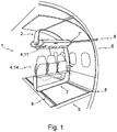
- FIG. 1 to 2 illustrate schematic views of exemplary embodiments of the present invention.
- a module for an aircraft is shown, wherein the aircraft having a fuselage structure 6 and a floor element 5.
- the floor element 5 defining a floor plane.
- the module comprises a frame device 2 wherein the frame device 2 is adapted for mounting a functional element 4.
- the frame device 2 is adapted for attachment to the floor element 5 of the aircraft at a first location 7 in the floor plane and wherein the frame device 2 is adapted for attachment to the fuselage structure 6 of the aircraft at a second location 7'.
- the second location 7' is thereby not in the floor plane.
- a rail element 8 whereby the frame device 2 can be fixed relocatable respectively movable to the rail 8.
- an aircraft seat 14 or an overhead stowage bin 11 as functional element 4
- an easy relocation of the whole module 1 can be provided.
- all necessary overhead functional elements such as oxygen masks, lighting or air condition need to be adapted separately to the new seat position.
- the overhead functional elements 4, 11 will be relocated automatically.
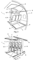
- Fig.1 shows thereby an open frame shape 2, wherein Fig 2 and 3 illustrate a closed frame shape 2.
- Fig 2 and 3 illustrate a closed frame shape 2.
- Fig. 3 shows an example of supported standing places for passengers.
- the centre of gravity of the passengers body is thereby very high above the floor 5, so that by fixing the support 14 just on the floor section 3 will lead to high torques.
- the frame device 2 By means of the frame device 2 the frame surround the centre of gravity, so that high torques are avoided.
- Fig. 4 illustrates a damper element 3 integrated in a rail in order to absorb 16g loads.
- Fig. 5 shows a schematic view of a damper integrated in a frame device in order to absorb 16 g loads
- Fig. 6 shows a schematic total view of a frame device 2 of a module 1, which is movably connected to the rail element 8. As shown a plurality of connection elements 3 that are connected to the rail elements 8 can be provided in order to reinforce the connection between the module 1 and the fuselage 6.
- Fig. 6 illustrates an open frame 2 with its open portion at the upper end of the surrounded area and hence describing a U-shape that allows the use of the module 1 in combination with a conventional longitudinal bin 11.
- the typical layout flexibility of the module is provided by all functional elements of a PSU being contained in a horizontal beam that is connected to the U-shaped frame 2.
- Fig. 7 shows an exemplary construction for attaching the module 1 relocatably and moveable to the fuselage structure 6 and the floor element 5.
- Rails it is possible to provide an easy constructive method for moving the frame devices 2 respectively the module 1.
- Connection elements 3 may be fixed to the frame device and are movably engaged with the rail 8.
- the frame device 2 provides thereby a closed, surrounding shape.
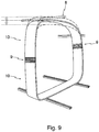
- Fig. 8 and 9 illustrate a frame device 2 that is connected to a fuselage 6, wherein an additional adapting element 9 is included.
- the adapting element 9 is connected to the frame device for adapting relative movements between the fuselage 6 and the frame device 2.
- Fig. 8 the frame device 2 adapts to the relative movements of the fuselage structure 2 by means of an adapting lever 9.
- Fig.9 shows a schematic view of an exemplary adapting system of the module to the relative movement of the fuselage by means of a telescoping element within the frame device.
- Fig. 10 and 11 show a further exemplary embodiment of the present invention whereby the functional elements 4, 5 can be relocatably fixed to the frame device 2.
- the functional element 4 is fixed thereby adjustable to the frame device 2 to enable an adjustment.
- simple constructions can be provided, for instance by connecting the attachment elements or the functional elements eccentrically to the frame device 2.
- the functional elements here for instance the seats or the stowage bins, can be adjustable in height.
- Fig. 11 shows a more detailed view of an adjustable seat 14 that is adjustably mounted to the frame device 2.
- Fig. 12 shows an exemplary view of a seat layout with reduced seat pitch made possible thanks to an increased seat height.
- the increased seat height allows for an increased luggage volume below the seats.
- Fig. 12' shows an exemplary view of a seat layout with increased seat pitch but reduced seat height for more comfort.
- the modules not in use are stowed away in one end of the cabin.
- Figs. 13 to 15 are showing some exemplary embodiments of different frame shapes.
- Fig. 13 illustrates a closed, surrounding frame device 2 consisting of several frame elements 10.
- the frame elements 10 form two closed frames, wherein in the upper rectangle frame a stowage bin 11 can be located and in the lower rectangle a seat row 14 can be installed as shown in Fig. 13' .
- Figs. 14 and 14' show an open frame device consisting of frame elements 10 with an open shape, here in a C-shape.
- a step is provided wherein in the lower stage provides a functional element 4, for instance a seat element 14, and in the upper stage a stowage bin 11 for storing items.
- Figs. 15 and 15' show a further shape of the frame device 2 consisting of several frame elements 10 wherein a lower section builds a C-shape but also containing an upper section.
- a functional element 4 can be placed, for instance a seat element 14, whereas in the upper section a stowage bin 11 can be placed as a functional element 4.
- Fig. 16 and show a front view of a cross-section of a fuselage, wherein Fig 16 . shows a three level fuselage layout.
- all differently shaped frame devices 2 are installed for the various purposes.
- the shape of the frame device shown in Fig. 10 is installed on the right and the left side for providing an optimal cabin layout with optimized space saving installation.
- the middle of the second and third level frame devices according to Fig. 8 , 8' are installed for providing a space-saving cabin layout.
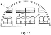
- Fig. 17 shows a single deck two aisle fuselage cross-section equipped with open frame modules 1. The open portion of the respective frame is adjacent to the respective aisle.
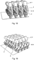
- Fig. 18 and 19 show three-dimensional views of cabin layouts according to an exemplary embodiment of the present invention.
- the frame devices 2 are curved either in longitudinal direction of the fuselage 6 or in such a way to conform to the shape of the sidewalls of the fuselage 6.
- the frame devices 2 By curving the frame devices 2 in a longitudinal direction of the fuselage 6, the field of vision of the passengers will be optimized.
- the frame shape of the frame device 2 with the fuselage structure 6 the available space in the cabin will be optimized and disturbing frame parts can follow the contour of the side panels of the aircraft structure.
- the frame shape can either be opened to the aisle side or the window side.
- the aisle between the seat rows can be kept free of any overhead elements such as stowage bins or oxygen masks, so that the available height increases the comfort level for the passengers.
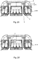
- Figs. 20 and 20' show an exemplary embodiment of the present invention wherein the stowage bins 11 are accessible in longitudinal direction of the fuselage.
- the aisle between the seats 14 in longitudinal direction can be kept free.
- the turnaround time can be shortened.
- individual stowage bins 11 for each passenger can be provided.
- the overhead stowage compartments 11 can be designed as fixed bins with a floor and an upper hinged lid to give access when stowing luggage or as movable bins which move downward around a pivot or by various kinematics like parallelograms or others. Luggage can also be stored under the passenger seats.
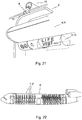
- Fig. 21 shows an exemplary embodiment of a supply system for the functional elements 4 or the functional tools 13.
- a supply connection 15 is fixed to the frame device 2, that can be adapted to be engageable with a supply element 16 of the fuselage structure 6.
- the supply connection 15 will remain connected with the supply element 16 of the fuselage.
- the supply connection 16 can be designed like a rail, including for instance air or electricity lines.
- the supply connection 15 of the module can be in slideable contact with the feeder-rail 16 and respectively in slideable contact with the supply sources.
- Fig. 22 shows a fuselage 6' wherein the frame devices 2 of the modules 1' are installed rigidly with the fuselage primary structure 6'.
- the fuselage frames can be built integrally with the frame device 2', so that weight and complexity of the fuselage construction can be reduced.
- Figs. 23 and 24 are showing further example of the module 1 comprising a plurality of frame devices 2.
- an upper frame device 2 is shown, wherein a functional element 4; 11 is installed.
- An independent second frame device 2' is installed on the lower side of the module 1 wherein a second functional element 4; 14 is installed.
- the upper and lower frame devices 2, 2' can be relocated independently.
- Fig. 23 illustrates a foldable seat element 14' for reducing the space requirements for a module 1.
- Fig. 24 shows an example of an installation of a stowage bin 11.
- the frame device 2 is connected to a rail element 8 by connection elements 3.
- the connection elements 3 are fixed to the fuselage structure 6 by two connecting points 3.
- the connecting line between the connecting points 3 runs through the centre of gravity of the stowage bin 11 in order to optimize the load distribution of the stowage bin 4, 11 and to minimize the torques.
Description
- This application claims the benefit of the filing date of European Patent Application No.
05 028 664.0 filed December 29, 2005 60/754,745 filed December 29, 2005 - The present invention relates to a module and a system for aircrafts.
- Today's commercial aircraft cabins are designed to accommodate passengers and their luggage by providing several distinct and largely independent components. More precisely, the individual passenger cabin environment is made up of seats, for instance including underseat stowage, life vests, information placards, literature pouches, plus overhead stowage bins including passenger service units, for instance reading lights, air outlets, information signs, loudspeakers and supplemental oxygen. These items are mostly designed by different parties and integrated or assembled on the aircraft in fixed locations with the specified spatial arrangement. Aircraft provisions for the attachment of seats are typically provided via floor structure with limited incremental positioning. Overhead stowage bins are installed in a fixed location and provide accommodation for PSU (Passenger Service Unit) components. The layout of a specific customer cabin is fixed to a certain configuration and involves a significant effort by the aircraft manufacturer to vary the installation and also on behalf of the customer to make adaptations in service.
- Further on, today's passengers carry personal belongings on board of the aircraft which have to be placed in stowage bins. The available space has to be shared with the others. This situation is derived from a classical baggage stowage compartment type, which is oriented longitudinally along the cabin, for instance in the x-direction respectively the longitudinal direction of the fuselage. The opening of the stowage bins is typically above the aisle orthogonal to the longitudinal direction of the fuselage, so that the passengers interfere themselves. This results in inefficient turnaround time and the poor access to the belongings during the flight.
- In the past, many different seat and stowage bin configurations and further partial solutions were accomplished to improve the space situation in the cabin of an aircraft.
- For instance,
DE 43 01 681 C1 describes a satellite like a PSU which can be shifted in longitudinal direction without disrupting any of its functions. All PSU functions are fed to the PSU.DE 195 02 658 C1 describes essentially the same functional principles for satellites, but the unit is supported by a flexible arm that allows the PSU to give way to the opening of a pivoting bin.DE 195 33 981 C1 reveals an arrangement with PSU functions around the individual passenger seat and unfolds a privacy umbrella when the seat is reclined. The feeding of the PSU function allowing for layout changes.DE 195 34 025 discloses PSU functions around the passenger seat and is designed in a column. The column can be part of the transversal seat structure or is separate flats transversal elements on the floor either in front of the seat or behind it and companying the seat roll without functional disruption when it is moved for a change of layout. -
US 3 142 461 , which is considered as being the closest prior art, relates to internal fittings of an aicraft and describes a freighter aircraft, in combination with a plurality of removable passenger-seating units each comprising a pallet bearing one or more seats, which units are such that they can be introduced into the freight compartment of the aircraft and arranged in positions therein at which the seats are appropriately placed for passenger-carrying with the pallets constituting false floor sections under the seats. In an example, each of the seating units comprises, on at least one side, a wall panel upstanding from the pallet to lie close up to and follow the contour of the side wall of the aircraft compartment. In an example, each unit is fitted with a ceiling panel above the seat or seats. When the units are in position in the aircraft, the wall panels, and also the ceiling panels, abut edge to edge to form a continuous wall surface, and in the case of ceiling panels a continuous false ceiling. - It is an object of the invention to provide a stable installation for functional elements.
- The object is solved by the subject-matter of the independent claim.
- According to an exemplary embodiment of the invention a module for an aircraft is provided, wherein the aircraft having a fuselage structure and a floor element. The floor element is defining a floor plane. The module comprises a frame device wherein the frame device is adapted for mounting a functional element. Further, the frame device is adapted for attachment to the floor element of the aircraft at a first location in the floor plane and the frame device is adapted for attachment to the fuselage structure of the aircraft at a second location. Thereby, the second location is not in the floor plane.
- According to a further exemplary embodiment of the invention, a system for providing a module for an aircraft is provided. The system comprises a plurality of modules according to the present invention and a control unit. The plurality of modules is adapted to be movable electrically, wherein the control unit is adapted to control the plurality of modules in such a way, that each of the plurality of modules is movable along a fuselage.
- According to an example, provided for further explanation, a method for an aicraft is provided. Thereby, a functional element is mounted to a frame device. The frame device is attached to a floor element of the aircraft at a first location in the floor plane and further on, the frame device is attached to the fuselage structure of the aircraft at a second location. Thereby, the floor element is defining a floor plane, wherein the second location is not in the floor plane.
- In the following, the expression "functional element" shall define for instance all installations in the cabin of an aircraft, that are installed in the environment of the passenger, such as seats, stowage bins, monuments, galleys, lavatories, movable class dividers, PSU's (passenger service units), lighting, air condition, loudspeakers, televisions, computers and oxygen masks etc..
- The wording fuselage structure shall define for instance the fuselage skin, the aircraft frames, the aircraft stringers or the cabinrelated parts. The wording floor element shall define for instance the different floor levels inside an aircraft.
- With the present invention it is possible to provide more stability for the connection of the functional elements. In order to meet current safety standards for functional elements it is necessary to design the connections of functional elements in such a manner, that the functional elements are able to withstand loads of 16 g in each direction. By using common connection methods, great effords have to be accomplished to comply with these requirements. As a result the connecting systems are very heavy and huge constructions. With the present invention, a lighter connection can be provided. By connecting the functional elements not exclusively in the floor plane but also in another plane, for instance to a fuselage structure, the forces that affect the functional elements can be reduced, because for instance the loads induced by acceleration torque can be minimized.
- According to the invention, the frame device surrounds the centre of gravity of the functional element. In an example, the frame device is connected to the functional element by at least two connection points, whereby the connection points are not located in the same plane. Thereby, the frame device surrounds the centre of gravity of the functional element, so that the an optimized load distribution of acceleration forces can be provided and torques reduced or avoided. Therewith the frame device provides more stability. If a connecting line between two connecting points of the frame device to the functional element runs through the centre of gravity of the functional element an optimized load distribution of the functional element can be provided.
- According to a further exemplary embodiment of the invention, the frame device is adapted for a slideable attachment to the floor element of the aircraft and the fuselage structure, such that the frame device is relocatable from a first position in the aircraft by a sliding movement to a second position in the aircraft. The second position can be at a distance in the longitudinal direction of the aircraft from the first position.
- With this exemplary embodiment a very flexible cabin layout can be provided. In airplanes many functional elements like oxygen masks, seats or air condition are often fixed to the floor elements or the fuselage structure. By changing the seat configuration, also the functional elements in the overhead area have to be changed accordingly to the new seat position. In common airplanes, the functional elements in the overhead area are fixed to the floor structure, so that it is very complicated to change their position. According to the present invention, the functional element is attached by an attachment element to a relocatable frame device. This frame device can be fixed to the primary aircraft structure or the secondary structure, such as the cabin related parts and the floor in such a way, that in case of changing the cabin layout or position of all functional elements, for instance a seat position, a further functional element for instance a stowage bin, will be repositioned automatically by changing the position of the frame device. Thus, a new cabin layout can be configured rapidly. By using the present invention, airliners could be able to adapt the capacity of their cabin layouts, such as for instance business or economy class layouts, to the amounts of the tickets sold for each class. Therefore, by changing the position of each module in a very short period of time, flexible capacities of i.e. business class or economy class can be configured by enlarging or reducing the distance between the modules respectively the seats. Very short turnaround times and an optimized utilization can be provided.
- According to a further exemplary embodiment of the invention, the floor element of the aircraft and the fuselage structure comprise a rail element. The rail element is adapted for mounting the frame device slideable in such a manner, that the frame device is relocatable along the rail element. With this rail principle, an efficient construction is provided to remove the module easily in direction of the rail. Depending on the forces that affect the module a plurality of rails can be provided on a plurality of connection points around the frame device in order to reinforce the fixation of the module. In case of changing the cabin configuration, the module can easily slide so that the reconfiguration time can be shortened.
- According to a further embodiment of the invention, the module further comprises a damper element. The damper element is thereby attached between the module and at least to one of the fuselage structure and the floor element. The damper element is adapted to reduce for instance the acceleration forces, that affect the module for instance in case of a 16 g crash deceleration. Therefore the maximum loads can be reduced by the damper element, so that the forces respectively acceleration/ deceleration loads at the connection points between the module and the fuselage or floor are minimized. According to a further embodiment of the invention, the damper element is located in the rail element or in the frame device.
- According to a further embodiment of the invention, the module further comprises an adapting element, whereby the adapting element is located between the module and at least to one of the fuselage structure and the floor element. Thereby, the relative movement between the fuselage structure or the floor elements and the module can be absorbed. During the flight the fuselage is deformed for instance by influence of the in-flight loads, so that the connection points can be designed flexible by using the adapting element. The adapting element can for instance consist of a flexible lever or telescoping halves of a frame device.
- According to a further exemplary embodiment of the invention the functional element is movable in respect to the frame device. Therewith, each position of the functional element can be placed individually along the frame device. For instance by using a seat element as first functional element, the height or the longitudinal position can be changed individually. For instance, by using a stowage bin as a functional element also the height of the stowage bin can be configured individually so that for instance smaller persons can access the stowage bin more easily. This can be realized by constructive elements for instance by fixing the attachment element to the frame device eccentrically. Also other constructions such as rails or a snap construction can be provided. Thus, the comfort for each passenger can be raised enormously because everybody can adjust his personal environment.
- According to a further exemplary embodiment of the invention, the frame device comprises a plurality of frame elements, wherein the frame elements are mounted detachably. By using a plurality of frame elements to generate a frame device, for instance the measures of the frame element can be designed individually. During the installation of the modules, it is much easier to carry the single frame elements into the aircraft than the whole frame device itself. Therewith the assembly and the installation of the frame device including the functional elements can be eased enormously.
- According to a further exemplary embodiment of the invention, the frame elements can be connected adjustable. Therewith an already installed frame device including the plurality of frame elements can be adjusted easily without reassembling the frame. Especially by changing the position of the module along the longitudinal direction of the fuselage of an aircraft, sometimes in the front and/or the rear end a smaller diameter than at the centre section can be encountered. Thus, the frames of the module have to be adjusted in case of sliding the modules along a fuselage. By using this exemplary embodiment of the present invention an adjustment of the module size, respectively the frame device, can be accomplished very fast and very easily.
- According to a further exemplary embodiment of the present invention, the plurality of frame elements are designed telescopically for providing for instance flexible measures of the frame device. According to a further exemplary embodiment of the present invention, the frame elements can also be adapted to be foldable.
- According to a further exemplary embodiment of the invention, each frame element of the plurality of frame elements has a different shape in comparison to the plurality of frame elements. Thus, a plurality of different shapes of the frame device can be accomplished, so that very flexible installations of the module in a fuselage of an aircraft can be provided.
- Favourite shapes in frame elements or frame device configurations can be closed, surrounding frame shapes, such as circles, rectangles or other closed shapes, but also open shaped frames like for instance frames with a C-shape, G-shape, I-shape, L-shape, A-shape, H-shape or T-shape etc..
- According to a further exemplary embodiment of the present invention, the module is adapted to be connectable to a primary aircraft structure in such a manner, that the module absorbs loads from the primary aircraft structure. The wording "Primary aircraft structure" defines all fuselage parts that are supporting the structure of a fuselage, such as frames and stringers. Therewith the functions of the fuselage primary structure and the frame device according to the present invention can be combined. By connecting the module to the primary aircraft structure in a load carrying manner, the inventive module of this embodiment can reinforce the primary aircraft structure. Thus, most of the structural frames or stringers can be combined or integrally performed with a module according to the present invention, so that the total weight of the structure and the costs can be reduced.
- According to a further exemplary embodiment of the present invention, the frame device is shaped in such a way, that the frame device conforms with the shape of at least one of the fuselage structure and the floor element. Thus, the frame device can be installed very space-saving in the aircraft fuselage and additionally no disturbing elements, such as frame pillars, can be recognized by the passengers.
- According to a further exemplary embodiment of the present invention, the functional element is mounted modularly to the frame device. Therewith the functional element can be replaced individually. For instance by using a seat device as first functional element, it can be very useful to exchange business class seats with economy class seats. Also by using restrooms as functional element the airliners can exchange easily and very fast the toilet instead of a row of seats. Thus, the airplane can provide more efficiency, because every airline can adapt cabin layouts according to their own needs.
- According to the present invention, the functional element consists of a transversal stowage bin.
- According to a further exemplary embodiment of the present invention, the transversal stowage bin comprising an opening for placing items in the transversal stowage bin, wherein the aircraft has a longitudinal direction in or against flight direction and wherein the opening is accessible in or against flight direction. In common passenger aircrafts, loading or unloading luggage into/ out of the stowage bins is very time consuming, because the openings of the stowage bins are accessible from the aisle of the cabin, respectively from an orthogonal direction to the longitudinal direction of the fuselage respectively to the flight direction. In case that one passenger tries to put items into the stowage bins it is impossible for other passengers to bypass this passenger along the aisle. By using the module according to this exemplary embodiment, each passenger can have his individual transversal stowage bin, that is operable from the transversal passage way between two neighbouring seat rows. Additionally by using this inventive transversal stowage bin assembly, it is possible to provide more space between the seat rows , because no overhead elements need to be installed above the transversal passage way between two seat rows. Thus, there is also more available space for each passenger. Further on, by installing separation walls in the transversal stowage bin, an individual stowage bin for each passenger can be provided.
- According to a further exemplary embodiment of the invention, the stowage bin comprises at least one functional tool, wherein the at least one functional tool is selected from the group consisting of lighting, air condition, loudspeakers, televisions, computers and oxygen masks. Thus, these functional tools can be fixed to the functional elements such as the stowage bin. Therewith by moving or relocating the module including the stowage bins, all functional tools will also be repositioned. The functional tools can also be fixed integrally or removable with a stowage bin.
- According to the invention, the functional element consists of a seat element.
- According to a further exemplary embodiment of the present invention, the seat element is adapted to be foldable, so that modules that are not in use can be pushed together and placed in a space-saving manner at one end of the cabin. For instance, if more first or business class seats are required, also more space between the modules respectively the seat rows is required, so that the excessive modules have to be stored in the cabin end. By folding the seats or also the stowage bins more modules can be stored easily.
- According to a further exemplary embodiment of the present invention, at least one of the first functional element and the second functional element is selected from the group of monuments, galleys, lavatories, PSUs, lighting, air condition, loudspeakers, televisions, computers and oxygen masks.
- According to a further exemplary embodiment of the invention, the module further comprises a supply connection for supplying at least one of the first functional element and the second functional element wherein the supply connection is adapted to be engageable with supply elements of the fuselage. Thereby, for instance a rail can be provided on the fuselage side to keep sliding contact in case the module is repositioned. By providing a flexible connection between the functional elements and the supply elements of at least one of the fuselage and the floor element, it is assured that even in case of relocating the modules, each of the functional elements is connectable to required sources, for instance electricity, cooling air or oxygen. Or all supplied functions like i.e. electricity, cooling air or oxygen can be provided by feeder rails, thus modules can relocated without disrupting any supply function.
- According to a further exemplary embodiment of the present invention, the frame device comprises a plurality of functional elements, for instance by using seats as a first functional element and stowage bins as second functional element, a frame device according to this exemplary embodiment can provide for instance a row of a random number of seats and a random number of stowage bins. By relocating the module, also all seats and stowage bins will be relocated in the same step. Also the desired amounts of other kinds of functional elements can be attached to one frame device.
- According to a further exemplary embodiment of the present invention, the module comprises a plurality of frame devices. Therewith it is possible, for instance, to design a module having an upper frame device including a functional element, for instance, a stowage bin and lighting, and having a second frame device including seats. Thus, it is possible to replace each frame device individually without a connection between the first frame device and the second frame device. Therewith more flexibility can be provided.
- Usable materials for frame devices can consist of carbon fibre, aluminium or various composite fibres, glare etc..
- According to a further example of the method, an adapting element adapts to the relative movements between the module and the fuselage.
- According to a further example of the method, a plurality of frame elements of the frame device is connected adjustably for providing flexible measures of the frame device.
- According to a further example of the method, the plurality of frame elements is modularly connected, wherein each frame element of the plurality of frame elements has a different shape in consideration to the plurality of frame elements.
- According to a further example of the method, the module is connected to the primary aircraft structure for absorbing loads in such a manner, that the module is part of the primary aircraft structure.
- According to a further example of the method, the functional element is mounted modularly for being exchangeable.
- According to a further example of the method, the functional element is supplied in such a way, that a supply connection of the module is connected with supply elements of at least one of the fuselage structure and the floor element. By using a feeder rail principle, a sliding contact between the module and the fuselage can be provided.
- According to a further example of the method, the frame device can be operated electrically for moving the module along at least one of the fuselage structure and the floor elements by means of a control unit.
- According to a further example, the module having the above- mentioned features is used in an aircraft.
- According to a further example , an aircraft comprising a module having the above mentioned features is provided.
- The exemplary embodiments of the module are also valid for the system and the method as well as for the use and the aircraft and inversely.
- In the following, exemplary embodiments of the present invention will be specified for further explanation and for better understanding with reference to the attached drawings:
- Fig. 1
- shows a schematic view of an exemplary embodiment of the module with an open frame shape according to the present invention;
- Fig. 2
- shows a schematic view of an exemplary embodiment of the module with a closed frame shape according to the present invention;
- Fig. 3
- shows a schematic view of an example of the module with an closed frame shape and supported standing places for passengers;
- Figs. 4
- schows a schematic view of a damper integrated in a rail in order to absorb 16g loads;
- Fig. 5
- shows a schematic view of a damper integrated in a frame device in order to absort 16 g loads;
- Fig. 6
- shows a schematic view of an open frame in a U-shape;
- Fig. 7
- show a schematic view of rails surrounding the centre of gravity of the module;
- Fig. 8
- shows a schematic view of an exemplary adapting system of the module to the relative movement of the fuselage by means of a lever;
- Fig. 9
- shows a schematic view of an exemplary adapting system of the module to the relative movement of the fuselage by means of a telescoping element within the frame device;
- Fig. 10 and 11
- show a schematic view of an exemplary embodiment for adjusting the functional elements;
- Fig. 12 and 12'
- shows the an exemplary arrangement of seats in two different seat pitches and heights;
- Fig. 13 and 15
- show exemplary embodiments of different frame shapes
- Fig. 16 and 17
- show exemplary front view of cross-sections including exemplary embodiments of different frame shapes ;
- Fig. 18 and 19
- showing a schematic view of a cabin layout according to one exemplary embodiment of the present invention;
- Fig. 20
- shows a schematic front view of a cabin layout according to an exemplary embodiment of the present invention;
- Fig. 21
- shows an exemplary view of a supplying system according to one exemplary embodiment of the present invention;
- Fig. 22
- shows a schematic view of an aircraft fuselage using the modules as a part of the aircraft primary structure according to one embodiment of the present invention; and
- Figs. 23 and 24
- show an example of the module comprising two independent frame devices.
- Similar or relating components in the several figures are provided with the same reference numerals. The view in the figures is schematic and not fully scaled.
-
Fig. 1 to 2 illustrate schematic views of exemplary embodiments of the present invention. A module for an aircraft is shown, wherein the aircraft having afuselage structure 6 and afloor element 5. Thefloor element 5 defining a floor plane. The module comprises aframe device 2 wherein theframe device 2 is adapted for mounting afunctional element 4. Theframe device 2 is adapted for attachment to thefloor element 5 of the aircraft at afirst location 7 in the floor plane and wherein theframe device 2 is adapted for attachment to thefuselage structure 6 of the aircraft at a second location 7'. The second location 7' is thereby not in the floor plane. - It is further illustrated a
rail element 8 whereby theframe device 2 can be fixed relocatable respectively movable to therail 8. By using as shown anaircraft seat 14 or anoverhead stowage bin 11 asfunctional element 4, an easy relocation of thewhole module 1 can be provided. In common aircraft cabin it is very complicated and time consuming to change the seat layout. When changing single seat positions, all necessary overhead functional elements such as oxygen masks, lighting or air condition need to be adapted separately to the new seat position. As shown inFig. 1 , by replacing theseat elements 14 of the described module, the overheadfunctional elements -
Fig.1 shows thereby anopen frame shape 2, whereinFig 2 and 3 illustrate aclosed frame shape 2. By using a closed frame shape, more stability can be provided. -
Fig. 3 shows an example of supported standing places for passengers. The centre of gravity of the passengers body is thereby very high above thefloor 5, so that by fixing thesupport 14 just on thefloor section 3 will lead to high torques. By means of theframe device 2 the frame surround the centre of gravity, so that high torques are avoided. -
Fig. 4 illustrates adamper element 3 integrated in a rail in order to absorb 16g loads. -
Fig. 5 shows a schematic view of a damper integrated in a frame device in order to absorb 16 g loads; -
Fig. 6 shows a schematic total view of aframe device 2 of amodule 1, which is movably connected to therail element 8. As shown a plurality ofconnection elements 3 that are connected to therail elements 8 can be provided in order to reinforce the connection between themodule 1 and thefuselage 6.Fig. 6 illustrates anopen frame 2 with its open portion at the upper end of the surrounded area and hence describing a U-shape that allows the use of themodule 1 in combination with a conventionallongitudinal bin 11. The typical layout flexibility of the module is provided by all functional elements of a PSU being contained in a horizontal beam that is connected to theU-shaped frame 2. -
Fig. 7 shows an exemplary construction for attaching themodule 1 relocatably and moveable to thefuselage structure 6 and thefloor element 5. By using rails it is possible to provide an easy constructive method for moving theframe devices 2 respectively themodule 1.Connection elements 3 may be fixed to the frame device and are movably engaged with therail 8. Theframe device 2 provides thereby a closed, surrounding shape. -
Fig. 8 and9 illustrate aframe device 2 that is connected to afuselage 6, wherein anadditional adapting element 9 is included. In this exemplary embodiment, the adaptingelement 9 is connected to the frame device for adapting relative movements between thefuselage 6 and theframe device 2. - In
Fig. 8 theframe device 2 adapts to the relative movements of thefuselage structure 2 by means of an adaptinglever 9. -
Fig.9 shows a schematic view of an exemplary adapting system of the module to the relative movement of the fuselage by means of a telescoping element within the frame device. -
Fig. 10 and 11 show a further exemplary embodiment of the present invention whereby thefunctional elements frame device 2. Thefunctional element 4 is fixed thereby adjustable to theframe device 2 to enable an adjustment. To realize the adjustability of thefunctional elements 4 simple constructions can be provided, for instance by connecting the attachment elements or the functional elements eccentrically to theframe device 2. As shown with the arrows inFig. 10 and 11 , the functional elements, here for instance the seats or the stowage bins, can be adjustable in height. -
Fig. 11 shows a more detailed view of anadjustable seat 14 that is adjustably mounted to theframe device 2. -
Fig. 12 shows an exemplary view of a seat layout with reduced seat pitch made possible thanks to an increased seat height. The increased seat height allows for an increased luggage volume below the seats. -
Fig. 12' shows an exemplary view of a seat layout with increased seat pitch but reduced seat height for more comfort. The modules not in use are stowed away in one end of the cabin. - The
Figs. 13 to 15 are showing some exemplary embodiments of different frame shapes.Fig. 13 illustrates a closed, surroundingframe device 2 consisting ofseveral frame elements 10. Theframe elements 10 form two closed frames, wherein in the upper rectangle frame astowage bin 11 can be located and in the lower rectangle aseat row 14 can be installed as shown inFig. 13' . -
Figs. 14 and 14' show an open frame device consisting offrame elements 10 with an open shape, here in a C-shape. On thebottom elements 10, a step is provided wherein in the lower stage provides afunctional element 4, for instance aseat element 14, and in the upper stage astowage bin 11 for storing items. -
Figs. 15 and 15' show a further shape of theframe device 2 consisting ofseveral frame elements 10 wherein a lower section builds a C-shape but also containing an upper section. In the lower section afunctional element 4 can be placed, for instance aseat element 14, whereas in the upper section astowage bin 11 can be placed as afunctional element 4. -
Fig. 16 and show a front view of a cross-section of a fuselage, whereinFig 16 . shows a three level fuselage layout. In the second and third level all differently shapedframe devices 2 are installed for the various purposes. In the middle stage for instance the shape of the frame device shown inFig. 10 is installed on the right and the left side for providing an optimal cabin layout with optimized space saving installation. In the middle of the second and third level frame devices according toFig. 8 , 8' are installed for providing a space-saving cabin layout. -
Fig. 17 shows a single deck two aisle fuselage cross-section equipped withopen frame modules 1. The open portion of the respective frame is adjacent to the respective aisle. -
Fig. 18 and 19 show three-dimensional views of cabin layouts according to an exemplary embodiment of the present invention. As illustrated, theframe devices 2 are curved either in longitudinal direction of thefuselage 6 or in such a way to conform to the shape of the sidewalls of thefuselage 6. By curving theframe devices 2 in a longitudinal direction of thefuselage 6, the field of vision of the passengers will be optimized. By conforming the shape of theframe device 2 with thefuselage structure 6, the available space in the cabin will be optimized and disturbing frame parts can follow the contour of the side panels of the aircraft structure. As shown, the frame shape can either be opened to the aisle side or the window side. - Additionally, as shown in
Fig. 18 and 19 , the aisle between the seat rows can be kept free of any overhead elements such as stowage bins or oxygen masks, so that the available height increases the comfort level for the passengers. -
Figs. 20 and 20' show an exemplary embodiment of the present invention wherein thestowage bins 11 are accessible in longitudinal direction of the fuselage. As seen inFig. 20' , by accessing thestowage bin 11 in longitudinal direction, the aisle between theseats 14 in longitudinal direction can be kept free. As a result the turnaround time can be shortened. By installing a dividing wall, alsoindividual stowage bins 11 for each passenger can be provided. The overhead stowage compartments 11 can be designed as fixed bins with a floor and an upper hinged lid to give access when stowing luggage or as movable bins which move downward around a pivot or by various kinematics like parallelograms or others. Luggage can also be stored under the passenger seats. -
Fig. 21 shows an exemplary embodiment of a supply system for thefunctional elements 4 or thefunctional tools 13. As seen inFig. 21 , asupply connection 15 is fixed to theframe device 2, that can be adapted to be engageable with asupply element 16 of thefuselage structure 6. When relocating theframe device 2, thesupply connection 15 will remain connected with thesupply element 16 of the fuselage. Thus, a supply will remain undisrupted for any position of themodule 1 along theentire fuselage 6. By using a feeder-rail principle, thesupply connection 16 can be designed like a rail, including for instance air or electricity lines. Thesupply connection 15 of the module can be in slideable contact with the feeder-rail 16 and respectively in slideable contact with the supply sources. -
Fig. 22 shows a fuselage 6' wherein theframe devices 2 of the modules 1' are installed rigidly with the fuselage primary structure 6'. By connecting the modules 1' rigidly to the aircraft primary structure 6' it is possible to absorb loads by the modules. Thus, the fuselage frames can be built integrally with the frame device 2', so that weight and complexity of the fuselage construction can be reduced. -
Figs. 23 and 24 are showing further example of themodule 1 comprising a plurality offrame devices 2. InFig. 23 anupper frame device 2 is shown, wherein afunctional element 4; 11 is installed. An independent second frame device 2' is installed on the lower side of themodule 1 wherein a secondfunctional element 4; 14 is installed. Thus, by changing the location of themodule 1, the upper andlower frame devices 2, 2' can be relocated independently. - Further on,
Fig. 23 illustrates a foldable seat element 14' for reducing the space requirements for amodule 1. -
Fig. 24 shows an example of an installation of astowage bin 11. Theframe device 2 is connected to arail element 8 byconnection elements 3. Theconnection elements 3 are fixed to thefuselage structure 6 by two connectingpoints 3. The connecting line between the connectingpoints 3 runs through the centre of gravity of thestowage bin 11 in order to optimize the load distribution of thestowage bin - It should be noted that the term "comprising" does not exclude other elements or steps and the "a" or "an" does not exclude a plurality. Also elements described in association with different embodiments may be combined.
- It should also be noted that reference signs in the claims shall not be construed as limiting the scope of the claims.
Claims (15)
- A module for an aircraft, the aircraft having a fuselage structure (6) and a floor element (5); the floor element (5) defining a floor plane, the module comprising:- a frame device (2); and- at least two functional elements (4);wherein the frame device (2) is adapted for mounting the at least two functional elements (4);
wherein the frame device (2) is adapted for surrounding a centre of gravity of the at least two functional elements (4);
wherein the frame device (2) is adapted for attachment to the floor element (5) of the aircraft at a first location (7) in the floor plane;
wherein the frame device (2) is adapted for attachment to the fuselage structure (6) of the aircraft at a second location (7');
wherein the second location (7') is not in the floor plane;
wherein the at least two functional elements comprise a seat (14) as a first functional element and a stowage bin (11) as a second functional element; and
wherein the at least two functional elements are mounted to the frame device. - Module according to claim 1, wherein the frame device (2) is adapted for a slideable attachment to the floor element (5) of the aircraft and the fuselage structure (6), such that the frame device (2) is relocatable from a first position in the aircraft by a sliding movement to a second position in the aircraft,
wherein the first position is at a distance in the longitudinal direction of the aircraft from the second position. - Module according to claim 2, wherein the floor element (5) of the aircraft and the fuselage structure (6) comprising a rail element (8); and
wherein the rail element (8) is adapted for mounting the frame device (2) slideable. - Module according to one of the claims 1 to 3, further comprising: a damper element (9);
wherein the damper element (9) is attached between the frame device (2) and at least one of the fuselage structure (6) and the floor elements (5). - Module according to claim 3 or 4, wherein the rail element (8) comprises a damper element (3) for reducing loads.
- Module according to one of the claims 1 to 5, wherein the module further comprises an adapting element (9); and
wherein the adapting element (9) is located between the frame device (2) and at least one of the fuselage structure (6) and the floor element (5) for adapting relative movements between the frame device (2) and the fuselage structure (6). - Module according to one of the claims 1 to 6, wherein the frame device (2) comprises a plurality of frame elements (10); and
wherein the frame elements (10) are mounted detachably. - Module according to claim 7, wherein the plurality frame elements (10) are connected adjustable.
- Module according to claim 7, wherein the plurality of frame elements (10) are designed telescopically adaptable.
- Module according to one of the claims 5 to 9, wherein the damper element (9) is attached between the frame elements (10).
- Module according to one of the claims 1 to 10, wherein the frame device (2) is shaped for conforming with a shape at least to one of the fuselage structure (6) and the floor element (5).
- Module according to one of the claims 1 to 11, wherein a further functional element is provided; and wherein the further functional element (4) is selected from the group consisting of monuments, galleys, lavatories, PSU's, lighting, air conditions, loudspeakers, televisions, computers and oxygen masks.
- Module according to one of the claims 1 to 12, the module further comprising:- a supply connection (15) for supplying the further functional element (4);wherein the supply connection (15) is adapted to be engagable with supply elements (16) of at least one of the fuselage structure (6) and the floor element (5); and
wherein the supply connection (15) is in slidable contact with the supply elements (16), for supplying the further functional element (4). - Module according to one of the claims 1 to 13, wherein the module (1) further comprises a plurality of frame devices (2).
- A system for providing modules for an aircraft, the system comprising:- a plurality of modules (1,1') according to one of the claims 1 to 14; and- a control unit;wherein the plurality of modules (1,1') are adapted to be moveable electrically; and
wherein the control unit is adapted for controlling the plurality of modules (1,1').
Priority Applications (2)
| Application Number | Priority Date | Filing Date | Title |
|---|---|---|---|
| EP06841173.5A EP1966046B1 (en) | 2005-12-29 | 2006-12-27 | Module for an aircraft |
| EP13180763.8A EP2664541A3 (en) | 2005-12-29 | 2006-12-27 | Module for an aircraft |
Applications Claiming Priority (4)
| Application Number | Priority Date | Filing Date | Title |
|---|---|---|---|
| US75474505P | 2005-12-29 | 2005-12-29 | |
| EP05028664.0A EP1803645B1 (en) | 2005-12-29 | 2005-12-29 | Module for an aircraft |
| EP06841173.5A EP1966046B1 (en) | 2005-12-29 | 2006-12-27 | Module for an aircraft |
| PCT/EP2006/012545 WO2007073938A1 (en) | 2005-12-29 | 2006-12-27 | Module for an aircraft |
Related Child Applications (2)
| Application Number | Title | Priority Date | Filing Date |
|---|---|---|---|
| EP13180763.8A Division EP2664541A3 (en) | 2005-12-29 | 2006-12-27 | Module for an aircraft |
| EP13180763.8A Division-Into EP2664541A3 (en) | 2005-12-29 | 2006-12-27 | Module for an aircraft |
Publications (2)
| Publication Number | Publication Date |
|---|---|
| EP1966046A1 EP1966046A1 (en) | 2008-09-10 |
| EP1966046B1 true EP1966046B1 (en) | 2019-04-17 |
Family
ID=36581853
Family Applications (3)
| Application Number | Title | Priority Date | Filing Date |
|---|---|---|---|
| EP05028664.0A Expired - Fee Related EP1803645B1 (en) | 2005-12-29 | 2005-12-29 | Module for an aircraft |
| EP06841173.5A Not-in-force EP1966046B1 (en) | 2005-12-29 | 2006-12-27 | Module for an aircraft |
| EP13180763.8A Withdrawn EP2664541A3 (en) | 2005-12-29 | 2006-12-27 | Module for an aircraft |
Family Applications Before (1)
| Application Number | Title | Priority Date | Filing Date |
|---|---|---|---|
| EP05028664.0A Expired - Fee Related EP1803645B1 (en) | 2005-12-29 | 2005-12-29 | Module for an aircraft |
Family Applications After (1)
| Application Number | Title | Priority Date | Filing Date |
|---|---|---|---|
| EP13180763.8A Withdrawn EP2664541A3 (en) | 2005-12-29 | 2006-12-27 | Module for an aircraft |
Country Status (8)
| Country | Link |
|---|---|
| US (2) | US9010686B2 (en) |
| EP (3) | EP1803645B1 (en) |
| JP (1) | JP2009522148A (en) |
| CN (1) | CN101351384B (en) |
| BR (1) | BRPI0620799A2 (en) |
| CA (1) | CA2632276A1 (en) |
| RU (1) | RU2414389C2 (en) |
| WO (1) | WO2007073938A1 (en) |
Families Citing this family (56)
| Publication number | Priority date | Publication date | Assignee | Title |
|---|---|---|---|---|
| DE102006061455A1 (en) * | 2006-12-23 | 2008-06-26 | DRäGER AEROSPACE GMBH | Arrangement of at least one personal service unit in a vehicle |
| DE102007050422B4 (en) * | 2007-10-22 | 2012-03-08 | Airbus Operations Gmbh | Aircraft component assembly system |
| DE102008013790B4 (en) * | 2008-03-12 | 2014-05-28 | Airbus Operations Gmbh | Separation system for reducing the propagation of light in an aircraft |
| DE102008025390A1 (en) * | 2008-05-28 | 2010-01-28 | Airbus Deutschland Gmbh | Arrangement for dividing a room into several areas |
| FR2935682B1 (en) | 2008-09-05 | 2011-06-17 | Airbus France | SEAT ASSEMBLY STRUCTURE FOR AN AIRCRAFT AND ADJUSTABLE FUSELAGE |
| DE102009014598A1 (en) | 2009-03-24 | 2010-09-30 | Airbus Deutschland Gmbh | Customizable monuments |
| DE102009014599A1 (en) * | 2009-03-24 | 2010-09-30 | Airbus Deutschland Gmbh | Integration of supply functions in a storage compartment |
| DE102009014606B4 (en) * | 2009-03-24 | 2012-06-06 | Airbus Operations Gmbh | Semi-automated procedure for reconfiguring a cabin layout |
| DE102009023400B4 (en) * | 2009-05-29 | 2014-07-10 | Airbus Operations Gmbh | A holder system for attaching an aircraft interior component to a transport device and an aircraft structure |
| DE102009023391A1 (en) * | 2009-05-29 | 2010-12-02 | Airbus Deutschland Gmbh | Method and system for assembling interior components in an aircraft |
| DE102009023401B4 (en) * | 2009-05-29 | 2014-06-26 | Airbus Operations Gmbh | Holder for mounting an interior component for mounting in an aircraft fuselage element on a transport device and transport device |
| DE102009043314B4 (en) * | 2009-09-28 | 2018-12-20 | Airbus Operations Gmbh | Cabin component connection system and method for modifying a passenger cabin configuration |
| US8262022B2 (en) * | 2009-12-15 | 2012-09-11 | The Boeing Company | Overhead stowage bin load transfer and balance system |
| US8590838B2 (en) | 2010-04-20 | 2013-11-26 | Be Intellectual Property, Inc. | Aircraft interior lavatory |
| DE102010035375A1 (en) * | 2010-08-25 | 2012-03-01 | Airbus Operations Gmbh | Arrangement for picking up passengers in a means of transport |
| DE102011009806A1 (en) * | 2011-01-31 | 2012-08-02 | Airbus Operations Gmbh | Fuselage segment for an aircraft fuselage, aircraft fuselage and aircraft |
| US9938015B2 (en) | 2011-04-04 | 2018-04-10 | C&D Zodiac, Inc. | Shared entrance seating arrangement |
| US20190023401A1 (en) * | 2011-04-04 | 2019-01-24 | C&D Zodiac, Inc. | Aircraft storage bin assembly with upper and lower bins |
| SG194104A1 (en) * | 2011-04-04 | 2013-11-29 | C & D Zodiac Inc | Seat shell and integrated overhead storage bin |
| USD749709S1 (en) | 2011-04-18 | 2016-02-16 | B/E Aerospace, Inc. | Aircraft interior lavatory |
| DE102011110010A1 (en) * | 2011-08-11 | 2013-02-14 | Airbus Operations Gmbh | Passenger supply module with integrated cabin lighting |
| EP2818412B1 (en) | 2012-02-23 | 2020-05-20 | The Yokohama Rubber Co., Ltd. | Installation method for airplane lavatory unit, and airplane |
| DE102012005148A1 (en) | 2012-03-13 | 2013-09-19 | Airbus Operations Gmbh | Passenger cabin for a vehicle and vehicle with a passenger cabin |
| US9359078B2 (en) * | 2012-03-28 | 2016-06-07 | B/E Aerospace, Inc. | Aircraft galley monument structure |
| US20130290221A1 (en) * | 2012-04-25 | 2013-10-31 | Satish Jindel | Passenger aircraft overhead bin system and method |
| JP5825192B2 (en) | 2012-05-11 | 2015-12-02 | 横浜ゴム株式会社 | Aircraft restroom unit and arrangement structure thereof |
| JP5849855B2 (en) | 2012-05-11 | 2016-02-03 | 横浜ゴム株式会社 | Aircraft restroom unit and arrangement structure thereof |
| CN110481788A (en) * | 2012-07-17 | 2019-11-22 | Be航天公司 | The space-efficient of commercial aircraft washes one's hands and face room module |
| JP2014076713A (en) | 2012-10-10 | 2014-05-01 | Yokohama Rubber Co Ltd:The | Aircraft toilet unit |
| JP5825240B2 (en) | 2012-10-12 | 2015-12-02 | 横浜ゴム株式会社 | Aircraft restroom unit |
| US9889936B2 (en) | 2012-10-30 | 2018-02-13 | The Boeing Company | Curved seating layout |
| US9359076B2 (en) | 2013-02-11 | 2016-06-07 | B/E Aerospace, Inc. | Compact aircraft galley and lavatory arrangement and articulating lavatory partition for an aircraft |
| US20150008283A1 (en) * | 2013-07-03 | 2015-01-08 | Zodiac Aerotechnics | Aircraft seating unit with fixture member |
| EP2821345A1 (en) * | 2013-07-03 | 2015-01-07 | Zodiac Aerotechnics | Aircraft seating unit with fixture member |
| GB2516433B (en) | 2013-07-19 | 2016-02-17 | British Airways Plc | Aircraft passenger seat fixing system |
| EP2848526B1 (en) * | 2013-09-11 | 2016-11-30 | Airbus Operations GmbH | Aircraft cabin partition monument with stowage compartment and method |
| US9561760B2 (en) * | 2013-10-11 | 2017-02-07 | The Boeing Company | Modular equipment center distributed equipment packaging truss |
| US9738402B2 (en) * | 2014-06-30 | 2017-08-22 | The Boeing Company | Flight test equipment installation system and method |
| DE112014006981B4 (en) * | 2014-09-24 | 2019-10-24 | Jamco Corporation | Galley unit for aircraft |
| CN104330026B (en) * | 2014-10-29 | 2017-06-09 | 上海飞机制造有限公司 | The detection means and its measuring method of aircraft seat sled position |
| AT516642A1 (en) | 2014-12-15 | 2016-07-15 | Facc Ag | Electrically actuated movable overhead luggage compartment for aircraft |
| EP3620377B1 (en) * | 2015-04-08 | 2022-11-09 | Safran Seats USA LLC | Privacy shell |
| DE102015114762A1 (en) | 2015-09-03 | 2017-03-09 | Recaro Aircraft Seating Gmbh & Co. Kg | Aircraft seat device with folding airplane seat |
| US10730629B2 (en) | 2016-01-26 | 2020-08-04 | Safran Seats | Stop for aircraft seat |
| DE102016108288A1 (en) * | 2016-05-04 | 2017-11-09 | Recaro Aircraft Seating Gmbh & Co. Kg | Rescue pocket |
| WO2017201207A1 (en) * | 2016-05-18 | 2017-11-23 | Airbus Group Hq Inc. Dba A3 By Airbus Group | Systems, devices, and methods for a modular passenger aircraft cabin and design thereof |
| JP2019519434A (en) * | 2016-05-18 | 2019-07-11 | エイ・キューブド・バイ・エアバス・エル・エル・シー | Autopilot aircraft for passenger or cargo transport |
| DE102016208516A1 (en) * | 2016-05-18 | 2017-11-23 | Siemens Aktiengesellschaft | Vehicle seat assembly and rail vehicle equipped therewith |
| US9936272B1 (en) * | 2016-09-30 | 2018-04-03 | The Boeing Company | Apparatuses and methods for acoustically exciting a face panel of a stowage bin inside a vehicle |
| EP3691970A4 (en) * | 2017-10-04 | 2021-06-02 | C&D Zodiac, Inc. | Aircraft storage bin assembly with upper and lower bins |
| US10933967B2 (en) * | 2017-12-15 | 2021-03-02 | Airbus Americas, Inc. | Partition wall in cabin of aircraft supporting monuments |
| JP7006552B2 (en) | 2018-09-25 | 2022-01-24 | 横浜ゴム株式会社 | Aircraft restroom unit |
| US11407484B2 (en) | 2019-06-14 | 2022-08-09 | Airbus Americas, Inc. | Standard cabin monument sub-structure |
| US11465747B2 (en) * | 2019-07-31 | 2022-10-11 | The Boeing Company | Overhead support platform system for a vehicle |
| US11679884B2 (en) * | 2020-12-01 | 2023-06-20 | The Nordam Group Llc | Aircraft seating module |
| US20220234742A1 (en) * | 2021-01-27 | 2022-07-28 | Antonio Alvarez | Aircraft Sanitizer |
Citations (1)
| Publication number | Priority date | Publication date | Assignee | Title |
|---|---|---|---|---|
| US3142461A (en) * | 1960-05-26 | 1964-07-28 | A T S Company Ltd | Internal fittings of aircraft |
Family Cites Families (111)
| Publication number | Priority date | Publication date | Assignee | Title |
|---|---|---|---|---|
| US628605A (en) * | 1898-10-17 | 1899-07-11 | Fanny R Ottenheimer | Hat-holding attachment for chairs. |
| US747489A (en) * | 1903-06-13 | 1903-12-22 | Myron Rounds | Electric car. |
| US1378210A (en) * | 1920-08-06 | 1921-05-17 | Alfred L Berry | Collapsible luggage-holder |
| US1829486A (en) * | 1929-02-16 | 1931-10-27 | Kimbrig Louis | Hat and coat holder |
| US2067585A (en) * | 1934-02-14 | 1937-01-12 | Curtiss Wright Corp | Gunner's seat and mounting |
| US2383173A (en) * | 1942-10-29 | 1945-08-21 | Budd Edward G Mfg Co | Airplane seat |
| US2985413A (en) * | 1958-07-08 | 1961-05-23 | Haraldo Juan Albrecht V Widman | Multi-directional anti-g device |
| US3173627A (en) * | 1963-03-08 | 1965-03-16 | Leonard A Cohen | Compostie space vehicle |
| US3610560A (en) * | 1969-12-03 | 1971-10-05 | Alan G Dillabough | Litter bag holder |
| US3632029A (en) * | 1969-12-29 | 1972-01-04 | May B Sonner | Litter bag |
| US3630566A (en) * | 1970-05-13 | 1971-12-28 | American Seating Co | End-supported vehicle seat |
| US3817434A (en) * | 1972-12-14 | 1974-06-18 | J Dickman | Concealed auto litter receptacle |
| DE2630210C3 (en) * | 1976-07-05 | 1979-10-18 | Hans Guido Dr. 8000 Muenchen Mutke | Device for the horizontal transport of people, in particular in aircraft |
| US4216927A (en) * | 1978-03-06 | 1980-08-12 | Air Cargo Equipment Corporation | Baggage handling and storage system |
| US4175723A (en) * | 1978-04-03 | 1979-11-27 | Great Lakes Carbon Corporation | Method and apparatus for neutralizing the effect of accelerating and decelerating forces |
| US4624502A (en) * | 1984-11-21 | 1986-11-25 | Boole Leon J | Portable drawer assembly |
| SU1362300A1 (en) | 1986-01-03 | 2005-02-10 | В.А. Кувшинов | DEVICE FOR SUSPENSION SCREEN IN THE SALON OF AIRPLANE |
| US4799631A (en) * | 1987-02-18 | 1989-01-24 | Atr International, Inc. | Aircraft shell module |
| GB8707485D0 (en) * | 1987-03-28 | 1987-04-29 | Flight Equipment & Eng Ltd | Armrest arrangements for vehicle seating |
| FR2630073B1 (en) * | 1988-04-14 | 1990-07-13 | Cimt Lorraine | TWO-STAGE RAILWAY CAR |
| GB8821066D0 (en) * | 1988-09-08 | 1988-10-05 | Magerik Ltd | Seating |
| US5015033A (en) * | 1989-12-20 | 1991-05-14 | Deana Winters | Underseat receptacle for purses and other possessions |
| US5083727A (en) * | 1990-01-02 | 1992-01-28 | The Boeing Company | Aircraft cabin system for selectivley locating interior units |
| US5104065A (en) * | 1990-02-20 | 1992-04-14 | The Boeing Company | Readily convertible aircraft passenger seats |
| US5131606A (en) * | 1991-04-01 | 1992-07-21 | Arnold Nordstrom | Seat pallet and cargo pallet restraining system |
| DE9116031U1 (en) | 1991-10-26 | 1992-03-12 | Frick, Hans-Ruedi, Weinfelden, Ch | |
| JP3241492B2 (en) * | 1992-08-03 | 2001-12-25 | トヨタ自動車株式会社 | Work sheet for assembling automotive parts |
| DE4301681C1 (en) * | 1993-01-22 | 1994-10-20 | Deutsche Aerospace Airbus | Pipe branch between an air line and an air shower |
| US5597139A (en) * | 1994-04-15 | 1997-01-28 | Burns Aerospace Corporation | Convertible passenger seat assembly |
| US5573288A (en) * | 1994-12-19 | 1996-11-12 | Sif Products Group Inc. | Portable seat cushion and storage device |
| DE19502658C1 (en) | 1995-01-28 | 1996-03-28 | Daimler Benz Aerospace Airbus | Control panel for passengers in aircraft |
| JPH0920293A (en) | 1995-07-10 | 1997-01-21 | Mitsubishi Heavy Ind Ltd | Structure of floor of cabin for aircraft |
| US6340136B1 (en) * | 1995-08-07 | 2002-01-22 | Fuselage Engineering Service, Ltd. | Compact storing and retrieving apparatus particularly useful for aircraft |
| US5716026A (en) * | 1995-08-14 | 1998-02-10 | Pascasio; Vidal | High-capacity, high-comfort split-level seating for transport and stationary applications |
| DE19534025C1 (en) * | 1995-09-14 | 1996-11-28 | Daimler Benz Aerospace Airbus | Service unit for aircraft passengers |
| DE19534024C2 (en) * | 1995-09-14 | 1997-07-10 | Daimler Benz Aerospace Airbus | Seating group, in particular in a passenger cabin of an aircraft |
| DE19533981C1 (en) | 1995-09-14 | 1996-12-19 | Daimler Benz Aerospace Airbus | Service unit for aircraft passengers |
| DE29515306U1 (en) | 1995-09-25 | 1995-11-23 | Kalff Franz Gmbh | Emergency aid bag |
| DE19540929C2 (en) * | 1995-11-03 | 1997-08-14 | Daimler Benz Aerospace Airbus | Luggage rack in a passenger cabin, especially in a commercial aircraft |
| US5772370A (en) * | 1995-11-22 | 1998-06-30 | Moore; Donal | Retractable and/or removable net type cargo restraining system |
| US5740989A (en) * | 1995-12-26 | 1998-04-21 | Daines; Paul H. | Lay down seat mechanism |
| FR2755656B1 (en) | 1996-11-08 | 1998-12-31 | Peugeot | DEVICE FOR STORING OR RETAINING OBJECTS IN A MOTOR VEHICLE |
| US5816650A (en) * | 1997-02-21 | 1998-10-06 | Lear Corporation | Underseat storage bin for motor vehicles |
| US5820210A (en) * | 1997-05-22 | 1998-10-13 | Shipman; Russell P. | Storage device for seating |
| US5927800A (en) * | 1997-09-08 | 1999-07-27 | Stallworth; Marcus | Theater trash bag |
| US6082816A (en) * | 1997-10-08 | 2000-07-04 | The Jeremy Group | Chair storage unit |
| US6053570A (en) * | 1998-05-21 | 2000-04-25 | Stern; Cindy Jane | Detachable storage device positionable under theater seats |
| US6056239A (en) * | 1998-08-12 | 2000-05-02 | Carlos Martinez Celis Cantu | Convertible seating and sleeping accommodations for aircraft |
| DE19839701C2 (en) * | 1998-09-01 | 2003-07-24 | Airbus Gmbh | Luggage rack arrangement in an aircraft passenger cabin |
| US20010050499A1 (en) * | 2000-02-12 | 2001-12-13 | Deloach Vera A. | School bus underseat storage container and method |
| DE10008258B4 (en) * | 2000-02-23 | 2006-07-13 | Airbus Deutschland Gmbh | Passenger support device for an aircraft passenger cabin |
| DE10052591B4 (en) | 2000-03-09 | 2005-01-27 | Airbus Deutschland Gmbh | Passenger seat for an aircraft passenger cabin |
| DE10052594C2 (en) | 2000-03-09 | 2002-03-21 | Airbus Gmbh | Device for orientation in a passenger cabin of an aircraft |
| ATE273832T1 (en) * | 2000-03-09 | 2004-09-15 | Airbus Gmbh | PASSENGER SEAT FOR AN AIRCRAFT PASSENGER CABIN |
| DE10052593A1 (en) | 2000-03-09 | 2001-09-20 | Eads Airbus Gmbh | Passenger seat with a device for receiving seat-related accessories and waste |
| DE10052595A1 (en) | 2000-03-09 | 2001-09-20 | Eads Airbus Gmbh | Passenger seat with security equipment |
| ES2226992T3 (en) * | 2000-03-09 | 2005-04-01 | Airbus Deutschland Gmbh | PASSENGER SEAT WITH SECURITY MEANS. |
| EP1132291B1 (en) * | 2000-03-09 | 2004-11-03 | Airbus Deutschland GmbH | Seat row with aircraft cabin orientation device |
| ES2228671T3 (en) * | 2000-03-09 | 2005-04-16 | Airbus Deutschland Gmbh | PASSENGER SEAT WITH A DEVICE TO ACCOMMODATE SEAT ACCESSORIES AND WASTE. |
| JP2001315581A (en) * | 2000-05-09 | 2001-11-13 | Fuji Heavy Ind Ltd | Vehicular cargo holding device |
| US6609744B2 (en) * | 2000-06-29 | 2003-08-26 | Collins & Aikman Products Co. | Collapsible storage apparatus for vehicle cargo compartments |
| DE10056043C2 (en) * | 2000-11-11 | 2003-04-10 | Daimler Chrysler Ag | Vehicle, in particular combined vehicle |
| JP3573707B2 (en) * | 2000-11-22 | 2004-10-06 | 株式会社ジャムコ | Expandable lavatory unit for aircraft |
| US6601798B2 (en) * | 2001-06-26 | 2003-08-05 | The Boeing Company | Seat track mounted passenger interface |
| US6581876B2 (en) * | 2001-07-25 | 2003-06-24 | The Boeing Company | Aircraft multi-function overhead space access module |
| US6494404B1 (en) * | 2001-08-14 | 2002-12-17 | John C. Meyer | Passenger airplane container system |
| DE10143438A1 (en) * | 2001-09-05 | 2003-03-27 | Recaro Aircraft Seating Gmbh | Lifejacket pouch in the form of a pocket for locating beneath the seat surface of an aircraft seat comprises a pair of retaining elements having a press-stud closure and a tie strip having an opening which the press-stud closure extends |
| US6834833B2 (en) * | 2001-10-02 | 2004-12-28 | The Boeing Company | Twin aisle small airplane |
| AT413812B (en) * | 2001-10-17 | 2006-06-15 | Fischer Adv Components Gmbh | SUSPENSION DEVICE FOR SLEEVABLE BIN STORAGE TANKS |
| DE20120481U1 (en) | 2001-12-18 | 2003-05-15 | Hymer Leichtmetallbau | Luggage compartment for land, sea or aircraft is constructed as rocker in form of two-arm lever which pivots on horizontal hinge point, with front wall forming one section of lever and bottom and rear wall forming other section |
| DE10214104C1 (en) * | 2002-03-28 | 2003-12-11 | Airbus Gmbh | Vehicle seat, in particular passenger seat |
| FR2840281B1 (en) * | 2002-05-30 | 2004-12-17 | Airbus | LUGGAGE BOX FOR AIRCRAFT |
| DE10224048B4 (en) | 2002-05-31 | 2006-07-13 | Airbus Deutschland Gmbh | Passenger seat, especially for a commercial aircraft |
| US6899299B2 (en) * | 2002-07-26 | 2005-05-31 | The Boeing Company | Luggage bins and aircraft passenger cabin ceilings |
| US6776373B1 (en) * | 2003-02-19 | 2004-08-17 | Robert N. Talmage, Jr. | Aircraft escape cabin |
| US7066551B2 (en) * | 2003-04-28 | 2006-06-27 | Be Aerospace, Inc. | Curved beam aircraft passenger seat |
| US7252267B2 (en) * | 2003-10-17 | 2007-08-07 | The Boeing Company | Aircraft archway architecture |
| US20060006704A1 (en) * | 2003-12-15 | 2006-01-12 | Be Aerospace, Inc. | Vehicle seating with storage feature |
| DE102004002169B4 (en) | 2004-01-12 | 2007-06-28 | Airbus Deutschland Gmbh | Vehicle seat, in particular passenger seat |
| US7934679B2 (en) | 2004-02-20 | 2011-05-03 | Singapore Airlines Limited | Aircraft cabin |
| DE102004012480A1 (en) | 2004-03-15 | 2005-10-06 | Airbus Deutschland Gmbh | Folding seat for passenger cabin of aircraft, has seat area pivoted upwards against backrest and connected to armrest via lever in force-coupled manner, and gas pressure spring that dampens movement of seat area and armrest |
| EP1577152B1 (en) * | 2004-03-15 | 2010-06-09 | Airbus Operations GmbH | Retractable seat |
| US6883753B1 (en) * | 2004-03-25 | 2005-04-26 | The Boeing Company | Overhead bin and monument attachment support system |
| US7188805B2 (en) * | 2004-03-27 | 2007-03-13 | The Boeing Company | Continuous power bus for seat power |
| FR2869289B1 (en) * | 2004-04-27 | 2007-07-13 | Eads Sogerma Services Sa | INTERIOR ARRANGEMENT OF THE WINDOWS OF AN AIRCRAFT FUSELAGE. |
| DE202004008069U1 (en) | 2004-05-13 | 2004-07-29 | Tricon Aktiengesellschaft | Seat assembly for especially passengers in aircraft has stowage compartment for hand luggage and is located below level of sitting surface or below foot level, with sitting surface raised by the height of stowage compartment |
| DE502005007173D1 (en) * | 2004-05-21 | 2009-06-10 | Airbus Gmbh | Passenger seat with integrated spring element |
| DE102004025125A1 (en) | 2004-05-21 | 2005-12-15 | Airbus Deutschland Gmbh | Aircraft seat includes resetting element for spring action mounted within volume of seat element or backrest element to provide clearer access for passenger movement |
| DE102004025982B4 (en) | 2004-05-27 | 2008-12-04 | Airbus Deutschland Gmbh | Zweiholmerchassis for passenger seat |
| US7232095B2 (en) * | 2004-09-08 | 2007-06-19 | The Boeing Company | Overhead rest assembly |
| US7261786B2 (en) * | 2004-09-16 | 2007-08-28 | The Boeing Company | Filament wound crew rest enclosure structure |
| US7201421B2 (en) * | 2005-02-11 | 2007-04-10 | Lear Corporation | Rear vehicle storage system |
| WO2006094091A2 (en) * | 2005-02-28 | 2006-09-08 | Ipventure, Inc. | Comfortable seating arrangements with easy access |
| DE102005015142A1 (en) * | 2005-03-31 | 2006-10-05 | Recaro Aircraft Seating Gmbh & Co. Kg | Comfort system for a seat, in particular for consecutively arranged in series Fahr- and passenger seats |
| US7455263B2 (en) * | 2005-04-22 | 2008-11-25 | The Boeing Company | Airplane interior systems |
| US7712704B2 (en) * | 2005-06-07 | 2010-05-11 | Airbus | Arrangement of seats and baggage compartments in an aircraft cabin |
| US7703718B2 (en) * | 2005-06-10 | 2010-04-27 | Airbus | Aircraft cabin arrangement and storage unit |
| GB0512541D0 (en) * | 2005-06-20 | 2005-07-27 | James Park Associates Ltd | Aircraft interior module |
| DE102005042403B8 (en) * | 2005-09-06 | 2008-01-10 | Airbus Deutschland Gmbh | Modular seating system for a vehicle |
| US7770523B2 (en) * | 2005-10-07 | 2010-08-10 | University Of South Florida | Interactive amusement park attraction vehicle |
| DE102006048998A1 (en) * | 2005-12-29 | 2007-07-12 | Airbus Deutschland Gmbh | Module for e.g. commercial aircraft, has frame device, which mounts aircraft functional element e.g. aircraft seat, mounted at two separate locations on flooring and fuselage structure of aircraft |
| ES1063217Y (en) * | 2006-02-20 | 2007-01-16 | Fernandez Javier Valverde | MOBILE SEAT FOR VEHICLES |
| DE102006039291A1 (en) * | 2006-08-22 | 2008-03-13 | Airbus Deutschland Gmbh | Frame element for use in installation of storage bin in aircraft, has longitudinal parallel struts that extend parallel to ribs of aircraft structure, when frame element is mounted to aircraft structure |
| US7723935B2 (en) * | 2006-08-25 | 2010-05-25 | The Boeing Company | System and method for compartment control |
| US7871039B2 (en) * | 2007-05-22 | 2011-01-18 | The Boeing Company | Modular passenger seat for an aircraft |
| US7523993B1 (en) * | 2007-11-23 | 2009-04-28 | Nova Bus, Division De Groupe Volvo Canada Inc. | Passenger dorsal support |
| EP2483102B1 (en) * | 2007-12-17 | 2020-08-05 | Arjuna Indraeswaran Rajasingham | Aircraft occupant support and method |
| DE102009014598A1 (en) * | 2009-03-24 | 2010-09-30 | Airbus Deutschland Gmbh | Customizable monuments |
| DE102009024157A1 (en) * | 2009-06-08 | 2011-03-03 | Airbus Operations Gmbh | System and method for manufacturing a vehicle cabin |
| US20120074258A1 (en) * | 2010-09-23 | 2012-03-29 | Be Intellectual Property, Inc. | Integrated aircraft interior |
| SG194104A1 (en) * | 2011-04-04 | 2013-11-29 | C & D Zodiac Inc | Seat shell and integrated overhead storage bin |
-
2005
- 2005-12-29 EP EP05028664.0A patent/EP1803645B1/en not_active Expired - Fee Related
-
2006
- 2006-12-27 BR BRPI0620799-5A patent/BRPI0620799A2/en not_active IP Right Cessation
- 2006-12-27 WO PCT/EP2006/012545 patent/WO2007073938A1/en active Application Filing
- 2006-12-27 JP JP2008547897A patent/JP2009522148A/en active Pending
- 2006-12-27 EP EP06841173.5A patent/EP1966046B1/en not_active Not-in-force
- 2006-12-27 RU RU2008130999A patent/RU2414389C2/en not_active IP Right Cessation
- 2006-12-27 EP EP13180763.8A patent/EP2664541A3/en not_active Withdrawn
- 2006-12-27 CN CN2006800499494A patent/CN101351384B/en not_active Expired - Fee Related
- 2006-12-27 CA CA 2632276 patent/CA2632276A1/en not_active Abandoned
- 2006-12-27 US US12/087,328 patent/US9010686B2/en active Active
-
2015
- 2015-03-17 US US14/660,268 patent/US20150259067A1/en not_active Abandoned
Patent Citations (1)
| Publication number | Priority date | Publication date | Assignee | Title |
|---|---|---|---|---|
| US3142461A (en) * | 1960-05-26 | 1964-07-28 | A T S Company Ltd | Internal fittings of aircraft |
Also Published As
| Publication number | Publication date |
|---|---|
| CA2632276A1 (en) | 2007-07-05 |
| US20090283636A1 (en) | 2009-11-19 |
| US9010686B2 (en) | 2015-04-21 |
| EP2664541A3 (en) | 2017-12-13 |
| EP2664541A2 (en) | 2013-11-20 |
| CN101351384A (en) | 2009-01-21 |
| WO2007073938B1 (en) | 2007-08-09 |
| JP2009522148A (en) | 2009-06-11 |
| EP1966046A1 (en) | 2008-09-10 |
| EP1803645B1 (en) | 2020-03-11 |
| RU2008130999A (en) | 2010-02-10 |
| CN101351384B (en) | 2010-09-29 |
| WO2007073938A1 (en) | 2007-07-05 |
| EP1803645A1 (en) | 2007-07-04 |
| US20150259067A1 (en) | 2015-09-17 |
| RU2414389C2 (en) | 2011-03-20 |
| BRPI0620799A2 (en) | 2011-11-22 |
Similar Documents
| Publication | Publication Date | Title |
|---|---|---|
| EP1966046B1 (en) | Module for an aircraft | |
| US20200298976A1 (en) | Aircraft lounge assembly | |
| EP2694371B1 (en) | Seat shell and integrated overhead storage bin | |
| US9266613B2 (en) | Seating arrangement | |
| EP2134596B1 (en) | Under-floor system for an aircraft | |
| EP3835205B1 (en) | Seat unit and passenger seating arrangement | |
| US11312495B2 (en) | Compact seat assembly for a vehicle | |
| US20210107656A1 (en) | Seating systems and methods for an internal cabin of an aircraft | |
| EP3126241B1 (en) | Shared entrance seating arrangement | |
| EP4015385B1 (en) | Aircraft passenger seat row with cabin attendant seat | |
| EP3691970A1 (en) | Aircraft storage bin assembly with upper and lower bins |
Legal Events
| Date | Code | Title | Description |
|---|---|---|---|
| PUAI | Public reference made under article 153(3) epc to a published international application that has entered the european phase |
Free format text: ORIGINAL CODE: 0009012 |
|
| 17P | Request for examination filed |
Effective date: 20080624 |
|
| AK | Designated contracting states |
Kind code of ref document: A1 Designated state(s): AT BE BG CH CY CZ DE DK EE ES FI FR GB GR HU IE IS IT LI LT LU LV MC NL PL PT RO SE SI SK TR |
|
| DAX | Request for extension of the european patent (deleted) | ||
| 17Q | First examination report despatched |
Effective date: 20160421 |
|
| STAA | Information on the status of an ep patent application or granted ep patent |
Free format text: STATUS: EXAMINATION IS IN PROGRESS |
|
| GRAP | Despatch of communication of intention to grant a patent |
Free format text: ORIGINAL CODE: EPIDOSNIGR1 |
|
| STAA | Information on the status of an ep patent application or granted ep patent |
Free format text: STATUS: GRANT OF PATENT IS INTENDED |
|
| INTG | Intention to grant announced |
Effective date: 20181106 |
|
| GRAS | Grant fee paid |
Free format text: ORIGINAL CODE: EPIDOSNIGR3 |
|
| GRAA | (expected) grant |
Free format text: ORIGINAL CODE: 0009210 |
|
| STAA | Information on the status of an ep patent application or granted ep patent |
Free format text: STATUS: THE PATENT HAS BEEN GRANTED |
|
| AK | Designated contracting states |
Kind code of ref document: B1 Designated state(s): AT BE BG CH CY CZ DE DK EE ES FI FR GB GR HU IE IS IT LI LT LU LV MC NL PL PT RO SE SI SK TR |
|
| REG | Reference to a national code |
Ref country code: GB Ref legal event code: FG4D |
|
| REG | Reference to a national code |
Ref country code: CH Ref legal event code: EP |
|
| REG | Reference to a national code |
Ref country code: DE Ref legal event code: R096 Ref document number: 602006057801 Country of ref document: DE |
|
| REG | Reference to a national code |
Ref country code: AT Ref legal event code: REF Ref document number: 1121275 Country of ref document: AT Kind code of ref document: T Effective date: 20190515 Ref country code: IE Ref legal event code: FG4D |
|
| REG | Reference to a national code |
Ref country code: NL Ref legal event code: MP Effective date: 20190417 |
|
| REG | Reference to a national code |
Ref country code: LT Ref legal event code: MG4D |
|
| PG25 | Lapsed in a contracting state [announced via postgrant information from national office to epo] |
Ref country code: NL Free format text: LAPSE BECAUSE OF FAILURE TO SUBMIT A TRANSLATION OF THE DESCRIPTION OR TO PAY THE FEE WITHIN THE PRESCRIBED TIME-LIMIT Effective date: 20190417 |
|
| PG25 | Lapsed in a contracting state [announced via postgrant information from national office to epo] |
Ref country code: FI Free format text: LAPSE BECAUSE OF FAILURE TO SUBMIT A TRANSLATION OF THE DESCRIPTION OR TO PAY THE FEE WITHIN THE PRESCRIBED TIME-LIMIT Effective date: 20190417 Ref country code: SE Free format text: LAPSE BECAUSE OF FAILURE TO SUBMIT A TRANSLATION OF THE DESCRIPTION OR TO PAY THE FEE WITHIN THE PRESCRIBED TIME-LIMIT Effective date: 20190417 Ref country code: PT Free format text: LAPSE BECAUSE OF FAILURE TO SUBMIT A TRANSLATION OF THE DESCRIPTION OR TO PAY THE FEE WITHIN THE PRESCRIBED TIME-LIMIT Effective date: 20190819 Ref country code: ES Free format text: LAPSE BECAUSE OF FAILURE TO SUBMIT A TRANSLATION OF THE DESCRIPTION OR TO PAY THE FEE WITHIN THE PRESCRIBED TIME-LIMIT Effective date: 20190417 Ref country code: LT Free format text: LAPSE BECAUSE OF FAILURE TO SUBMIT A TRANSLATION OF THE DESCRIPTION OR TO PAY THE FEE WITHIN THE PRESCRIBED TIME-LIMIT Effective date: 20190417 |
|
| PG25 | Lapsed in a contracting state [announced via postgrant information from national office to epo] |
Ref country code: PL Free format text: LAPSE BECAUSE OF FAILURE TO SUBMIT A TRANSLATION OF THE DESCRIPTION OR TO PAY THE FEE WITHIN THE PRESCRIBED TIME-LIMIT Effective date: 20190417 Ref country code: BG Free format text: LAPSE BECAUSE OF FAILURE TO SUBMIT A TRANSLATION OF THE DESCRIPTION OR TO PAY THE FEE WITHIN THE PRESCRIBED TIME-LIMIT Effective date: 20190717 Ref country code: LV Free format text: LAPSE BECAUSE OF FAILURE TO SUBMIT A TRANSLATION OF THE DESCRIPTION OR TO PAY THE FEE WITHIN THE PRESCRIBED TIME-LIMIT Effective date: 20190417 Ref country code: GR Free format text: LAPSE BECAUSE OF FAILURE TO SUBMIT A TRANSLATION OF THE DESCRIPTION OR TO PAY THE FEE WITHIN THE PRESCRIBED TIME-LIMIT Effective date: 20190718 |
|
| REG | Reference to a national code |
Ref country code: AT Ref legal event code: MK05 Ref document number: 1121275 Country of ref document: AT Kind code of ref document: T Effective date: 20190417 |
|
| PG25 | Lapsed in a contracting state [announced via postgrant information from national office to epo] |
Ref country code: IS Free format text: LAPSE BECAUSE OF FAILURE TO SUBMIT A TRANSLATION OF THE DESCRIPTION OR TO PAY THE FEE WITHIN THE PRESCRIBED TIME-LIMIT Effective date: 20190817 |
|
| REG | Reference to a national code |
Ref country code: DE Ref legal event code: R097 Ref document number: 602006057801 Country of ref document: DE |
|
| PG25 | Lapsed in a contracting state [announced via postgrant information from national office to epo] |
Ref country code: RO Free format text: LAPSE BECAUSE OF FAILURE TO SUBMIT A TRANSLATION OF THE DESCRIPTION OR TO PAY THE FEE WITHIN THE PRESCRIBED TIME-LIMIT Effective date: 20190417 Ref country code: SK Free format text: LAPSE BECAUSE OF FAILURE TO SUBMIT A TRANSLATION OF THE DESCRIPTION OR TO PAY THE FEE WITHIN THE PRESCRIBED TIME-LIMIT Effective date: 20190417 Ref country code: CZ Free format text: LAPSE BECAUSE OF FAILURE TO SUBMIT A TRANSLATION OF THE DESCRIPTION OR TO PAY THE FEE WITHIN THE PRESCRIBED TIME-LIMIT Effective date: 20190417 Ref country code: EE Free format text: LAPSE BECAUSE OF FAILURE TO SUBMIT A TRANSLATION OF THE DESCRIPTION OR TO PAY THE FEE WITHIN THE PRESCRIBED TIME-LIMIT Effective date: 20190417 Ref country code: AT Free format text: LAPSE BECAUSE OF FAILURE TO SUBMIT A TRANSLATION OF THE DESCRIPTION OR TO PAY THE FEE WITHIN THE PRESCRIBED TIME-LIMIT Effective date: 20190417 Ref country code: DK Free format text: LAPSE BECAUSE OF FAILURE TO SUBMIT A TRANSLATION OF THE DESCRIPTION OR TO PAY THE FEE WITHIN THE PRESCRIBED TIME-LIMIT Effective date: 20190417 |
|
| PGFP | Annual fee paid to national office [announced via postgrant information from national office to epo] |
Ref country code: DE Payment date: 20191210 Year of fee payment: 14 |
|
| PLBE | No opposition filed within time limit |
Free format text: ORIGINAL CODE: 0009261 |
|
| STAA | Information on the status of an ep patent application or granted ep patent |
Free format text: STATUS: NO OPPOSITION FILED WITHIN TIME LIMIT |
|
| PG25 | Lapsed in a contracting state [announced via postgrant information from national office to epo] |
Ref country code: IT Free format text: LAPSE BECAUSE OF FAILURE TO SUBMIT A TRANSLATION OF THE DESCRIPTION OR TO PAY THE FEE WITHIN THE PRESCRIBED TIME-LIMIT Effective date: 20190417 |
|
| PGFP | Annual fee paid to national office [announced via postgrant information from national office to epo] |
Ref country code: FR Payment date: 20191220 Year of fee payment: 14 |
|
| 26N | No opposition filed |
Effective date: 20200120 |
|
| PG25 | Lapsed in a contracting state [announced via postgrant information from national office to epo] |
Ref country code: TR Free format text: LAPSE BECAUSE OF FAILURE TO SUBMIT A TRANSLATION OF THE DESCRIPTION OR TO PAY THE FEE WITHIN THE PRESCRIBED TIME-LIMIT Effective date: 20190417 |
|
| PGFP | Annual fee paid to national office [announced via postgrant information from national office to epo] |
Ref country code: GB Payment date: 20191220 Year of fee payment: 14 |
|
| PG25 | Lapsed in a contracting state [announced via postgrant information from national office to epo] |
Ref country code: SI Free format text: LAPSE BECAUSE OF FAILURE TO SUBMIT A TRANSLATION OF THE DESCRIPTION OR TO PAY THE FEE WITHIN THE PRESCRIBED TIME-LIMIT Effective date: 20190417 |
|
| REG | Reference to a national code |
Ref country code: CH Ref legal event code: PL |
|
| REG | Reference to a national code |
Ref country code: BE Ref legal event code: MM Effective date: 20191231 |
|
| PG25 | Lapsed in a contracting state [announced via postgrant information from national office to epo] |
Ref country code: MC Free format text: LAPSE BECAUSE OF FAILURE TO SUBMIT A TRANSLATION OF THE DESCRIPTION OR TO PAY THE FEE WITHIN THE PRESCRIBED TIME-LIMIT Effective date: 20190417 |
|
| PG25 | Lapsed in a contracting state [announced via postgrant information from national office to epo] |
Ref country code: IE Free format text: LAPSE BECAUSE OF NON-PAYMENT OF DUE FEES Effective date: 20191227 Ref country code: LU Free format text: LAPSE BECAUSE OF NON-PAYMENT OF DUE FEES Effective date: 20191227 |
|
| PG25 | Lapsed in a contracting state [announced via postgrant information from national office to epo] |
Ref country code: BE Free format text: LAPSE BECAUSE OF NON-PAYMENT OF DUE FEES Effective date: 20191231 Ref country code: CH Free format text: LAPSE BECAUSE OF NON-PAYMENT OF DUE FEES Effective date: 20191231 Ref country code: LI Free format text: LAPSE BECAUSE OF NON-PAYMENT OF DUE FEES Effective date: 20191231 |
|
| PG25 | Lapsed in a contracting state [announced via postgrant information from national office to epo] |
Ref country code: CY Free format text: LAPSE BECAUSE OF FAILURE TO SUBMIT A TRANSLATION OF THE DESCRIPTION OR TO PAY THE FEE WITHIN THE PRESCRIBED TIME-LIMIT Effective date: 20190417 |
|
| REG | Reference to a national code |
Ref country code: DE Ref legal event code: R119 Ref document number: 602006057801 Country of ref document: DE |
|
| PG25 | Lapsed in a contracting state [announced via postgrant information from national office to epo] |
Ref country code: HU Free format text: LAPSE BECAUSE OF FAILURE TO SUBMIT A TRANSLATION OF THE DESCRIPTION OR TO PAY THE FEE WITHIN THE PRESCRIBED TIME-LIMIT; INVALID AB INITIO Effective date: 20061227 |
|
| GBPC | Gb: european patent ceased through non-payment of renewal fee |
Effective date: 20201227 |
|
| PG25 | Lapsed in a contracting state [announced via postgrant information from national office to epo] |
Ref country code: FR Free format text: LAPSE BECAUSE OF NON-PAYMENT OF DUE FEES Effective date: 20201231 |
|
| PG25 | Lapsed in a contracting state [announced via postgrant information from national office to epo] |
Ref country code: GB Free format text: LAPSE BECAUSE OF NON-PAYMENT OF DUE FEES Effective date: 20201227 Ref country code: DE Free format text: LAPSE BECAUSE OF NON-PAYMENT OF DUE FEES Effective date: 20210701 |