EP1965621A2 - Housing structure of acoustic controller - Google Patents
Housing structure of acoustic controller Download PDFInfo
- Publication number
- EP1965621A2 EP1965621A2 EP08101208A EP08101208A EP1965621A2 EP 1965621 A2 EP1965621 A2 EP 1965621A2 EP 08101208 A EP08101208 A EP 08101208A EP 08101208 A EP08101208 A EP 08101208A EP 1965621 A2 EP1965621 A2 EP 1965621A2
- Authority
- EP
- European Patent Office
- Prior art keywords
- lower case
- acoustic controller
- controller
- heat radiation
- concave
- Prior art date
- Legal status (The legal status is an assumption and is not a legal conclusion. Google has not performed a legal analysis and makes no representation as to the accuracy of the status listed.)
- Granted
Links
- 229920005989 resin Polymers 0.000 claims abstract description 14
- 239000011347 resin Substances 0.000 claims abstract description 14
- 230000005855 radiation Effects 0.000 claims description 51
- 238000001816 cooling Methods 0.000 description 5
- 229910052751 metal Inorganic materials 0.000 description 4
- 239000002184 metal Substances 0.000 description 4
- 230000002787 reinforcement Effects 0.000 description 3
- 238000005452 bending Methods 0.000 description 2
- 238000004891 communication Methods 0.000 description 2
- 230000007423 decrease Effects 0.000 description 2
- 230000003247 decreasing effect Effects 0.000 description 2
- 230000003014 reinforcing effect Effects 0.000 description 2
- 229910052782 aluminium Inorganic materials 0.000 description 1
- XAGFODPZIPBFFR-UHFFFAOYSA-N aluminium Chemical compound [Al] XAGFODPZIPBFFR-UHFFFAOYSA-N 0.000 description 1
- 230000015572 biosynthetic process Effects 0.000 description 1
- 238000010276 construction Methods 0.000 description 1
- 230000000694 effects Effects 0.000 description 1
- 238000010438 heat treatment Methods 0.000 description 1
- 238000009434 installation Methods 0.000 description 1
- 239000004973 liquid crystal related substance Substances 0.000 description 1
- 238000004519 manufacturing process Methods 0.000 description 1
- 238000000465 moulding Methods 0.000 description 1
- 229920003002 synthetic resin Polymers 0.000 description 1
- 239000000057 synthetic resin Substances 0.000 description 1
- 239000013585 weight reducing agent Substances 0.000 description 1
Images




Classifications
-
- H—ELECTRICITY
- H05—ELECTRIC TECHNIQUES NOT OTHERWISE PROVIDED FOR
- H05K—PRINTED CIRCUITS; CASINGS OR CONSTRUCTIONAL DETAILS OF ELECTRIC APPARATUS; MANUFACTURE OF ASSEMBLAGES OF ELECTRICAL COMPONENTS
- H05K7/00—Constructional details common to different types of electric apparatus
- H05K7/20—Modifications to facilitate cooling, ventilating, or heating
- H05K7/20536—Modifications to facilitate cooling, ventilating, or heating for racks or cabinets of standardised dimensions, e.g. electronic racks for aircraft or telecommunication equipment
- H05K7/20545—Natural convection of gaseous coolant; Heat transfer by conduction from electronic boards
-
- H—ELECTRICITY
- H04—ELECTRIC COMMUNICATION TECHNIQUE
- H04H—BROADCAST COMMUNICATION
- H04H60/00—Arrangements for broadcast applications with a direct linking to broadcast information or broadcast space-time; Broadcast-related systems
- H04H60/02—Arrangements for generating broadcast information; Arrangements for generating broadcast-related information with a direct linking to broadcast information or to broadcast space-time; Arrangements for simultaneous generation of broadcast information and broadcast-related information
- H04H60/04—Studio equipment; Interconnection of studios
Definitions
- the present invention relates to a housing structure of an acoustic controller, and more particularly, to a housing structure of an acoustic controller that makes the controller usable both in a stationarily placed state and in a rack-mounted state.
- an acoustic controller such as a mixer apparatus that can be used both in a state stationarily placed on a flat surface such as tabletop surface, desktop surface, and floor surface and in a state mounted on a rack. Since there are disposed circuit boards or other heat generating component parts in an acoustic controller housing, the interior of the housing must be cooled.
- Japanese Design Registration No. 1256520 discloses an acoustic controller in which heat radiation openings are formed in side walls of the housing for cooling the interior of the housing. Also known is an acoustic controller having heat radiation openings formed in a bottom surface of the housing.
- Japanese Patent Publication No. 3815559 discloses an acoustic controller (electronic apparatus) having intake ports formed in front and rear surfaces of a metallic housing (casing), circuit boards disposed vertically inside a rear part of the housing, and exhaust ports formed in an upper rear surface of the housing.
- acoustic controller electronic apparatus
- circuit boards disposed vertically inside a rear part of the housing
- exhaust ports formed in an upper rear surface of the housing.
- the acoustic controller disclosed in Japanese Design Registration No. 1256520 has a drawback that the efficiency of heat radiation becomes low when rack-mounted because of a small distance from the heat radiation openings of the housing to side walls of the rack.
- the above described prior art acoustic controller having heat radiation openings formed in the housing bottom surface also has a drawback that heat radiation efficiency is lowered when the controller is stationarily placed on a tabletop surface so that the distance between the heat radiation openings and the tabletop surface decreases.
- the acoustic controller disclosed in Japanese Patent Publication No. 3815559 has its housing having a large height (thickness) especially at the rear part thereof. If a lower part (lower case) of the controller housing is formed by a resin, such a resin lower case provides a smaller rigidity than that of a metal lower case. Besides, the resin lower case must be provided with thickened portions such as reinforcement ribs and bosses for mounting an upper unit (upper casing part) and circuit boards thereon. In the case of the lower case being large in thickness, the thickened portions formed therein become large in height, which can worsen the moldability of the lower case. Generally, a mixer apparatus is made larger in height at its rear part than at a front part thereof to improve the user's operability. In the acoustic controller disclosed in Japanese Patent Publication No. 3815559 having the circuit boards vertically disposed, the thickened portions formed at the rear part of the controller are noticeably large in height, which is disadvantageous in improving the moldability and poses a problem.
- the present invention provides a housing structure of an acoustic controller capable of increasing the rigidity of and improving the moldability of a lower case of the acoustic controller.
- the present invention also provides a housing structure of an acoustic controller capable of increasing the rigidity of a lower case of the acoustic controller and effectively cooling heat generating component parts provided therein.
- a housing structure of an acoustic controller comprising a housing comprised of a lower case and an upper unit having its operation panel surface, the acoustic controller being adapted to be usable both in a stationarily placed state where it is stationarily placed on a flat surface and in a rack-mounted state, wherein the lower case is integrally formed by a resin and has a bottom surface thereof adapted to face the flat surface when the acoustic controller is in the stationarily placed state, the bottom surface of the lower case has a concave-forming portion thereof which is convex upward when the acoustic controller is in the stationarily placed state, and at least one thickened portion is integrally formed in the concave-forming portion of the lower case to extend in a direction including a vertical direction component as viewed when the acoustic controller is in the stationarily placed state.
- the rigidity of the lower case can be increased by having the concave-forming portion in the bottom surface of the lower case, and the moldability of the lower case can be improved by having the thickened portion integrally formed in the lower case with a reduced height.
- the concave-forming portion of the lower case can be adapted to define a concave space communicating with outside of the acoustic controller when the acoustic controller is in the stationarily placed state, and the concave-forming portion can be formed with at least one first heat radiation opening.
- the housing can be formed with at least one second heat radiation opening that is disposed in a vertical positional relation to the first heat radiation opening when the acoustic controller is in the rack-mounted state.
- a smooth air flow can be generated between the first and second heat radiation openings when the acoustic controller is rack-mounted, whereby the interior of the housing can be sufficiently cooled when the controller is in the rack-mounted state.
- the thickened portion of the concave-forming portion of the lower case can be at least one of a boss for mounting the upper unit on the lower case, a boss for mounting a board on the lower case, and a rib for ensuring rigidity of the lower case.
- the moldability of the lower case can be improved by having the boss and/or the rib of a reduced height.
- a housing structure of an acoustic controller comprising a housing comprised of a lower case and an upper unit having its operation panel surface, the acoustic controller being adapted to be usable both in a stationarily placed state where it is stationarily placed on a flat surface and in a rack-mounted state, wherein the lower case is integrally formed by a resin and has a bottom surface thereof adapted to face the flat surface when the acoustic controller is in the stationarily placed state, the bottom surface of the lower case is formed with a concave-forming portion which is convex upward when the acoustic controller is in the stationarily placed state, at least one heat generating component part is disposed inside the housing, the concave-forming portion of the lower case has a part thereof formed with at least one heat radiation opening and extending in a direction including a vertical direction component as viewed when the acoustic controller is in the stationarily placed state, and the housing has at least one
- the rigidity of the lower case can be increased by having the concave-forming portion formed in the bottom surface of the lower case, and the heat generating component parts can effectively be cooled by having the first and second heat radiation openings formed in the housing.
- the first and second heat radiation openings can be disposed in a vertical positional relation to each other when the acoustic controller is in the rack-mounted state.
- a smooth air flow can be generated in the housing between the first and second heat radiation openings when the acoustic controller is rack-mounted, whereby the interior of the housing can be sufficiently cooled when the controller is in the rack-mounted state.
- FIG. 1A is a plan view showing an acoustic controller to which a housing structure according to one embodiment of this invention is applied;
- FIG. 1B is a right side view of the acoustic controller
- FIG. 2A is a perspective view of the acoustic controller as seen from obliquely above;
- FIG. 2B is a perspective view of the acoustic controller as seen from obliquely below;
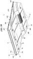
- FIG. 3 is a perspective view of a lower case as seen from obliquely above;
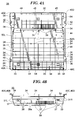
- FIG. 4A is a plan view of the lower case
- FIG. 4B is a front view of the lower case
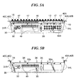
- FIG. 5A is a rear view of the acoustic controller
- FIG. 5B is a rear view of the lower case
- FIG. 6 is a section view taken along line A-A shown in FIG. 1A .
- FIGS. 1A and 1B respectively show in plan view and right side view an acoustic controller to which a housing structure according to one embodiment of this invention is applied.
- the acoustic controller 1 is configured as a so-called mixer apparatus, and includes a housing comprised of an upper unit 10 and a lower case 30, which are adapted to be assembled together.
- the acoustic controller 1 is configured to be usable in either state of being stationarily placed on a flat surface of a floor, a tabletop or the like (hereinafter referred to as “in stationarily placed state” or “in stationary use”) or being mounted to a rack 51 (hereinafter referred to as “in rack-mounted state” or “in rack mount use”).
- the vertical direction of the acoustic controller 1 is determined under an assumption that the controller is in stationary use although the direction of the controller is different between when the controller is in stationary use and in rack mount use.
- a user is on the side of a front surface 11 of the upper unit 10, which is a part of a front portion of the controller 1.
- a front surface 11 side of the upper unit 10 will be referred to as the "front side” of the controller 1
- a rear surface 12 side of the upper unit 10 which is a part of a rear portion of the controller will be referred to as the "rear side" of the controller unless otherwise specified.
- the acoustic controller 1 has an operation panel surface 13 on its upper side and has a plurality of legs 37 on its lower side. As shown in FIG. 1B , when the controller 1 is in stationary use, the legs 37 are made in contact with a tabletop surface 50, and a bottom plate 33 is disposed to face the tabletop surface 50. The controller 1 is made higher (thicker) toward the rear portion thereof. When the controller 1 is in stationary use, the operation panel surface 13 is inclined downward toward the front portion thereof for ease of user operation. It is assumed that a rack 51 is installed vertically. In that case, the operation panel surface 13 of the rack-mounted acoustic controller 1 extends vertically in a facing relation with the user. The angle of installation of the rack 51 is shown by way of example in FIGS. 1A and 1B . The rack 51 can be installed at any angle so long as the operation panel surface 13 is disposed in a direction suitable for easy user operation when the controller 1 is in rack mount use.
- FIGS. 2A and 2B show the acoustic controller 1 in perspective view
- FIG. 3 shows the lower case 30 in perspective view
- FIGS. 4A and 4B show the lower case 30 in plan view and front view
- FIGS. 5A and 5B show the acoustic controller 1 and the lower case 30 in rear view
- FIG. 6 is a section view taken along line A-A shown in FIG. 1A .
- FIG. 4B shows the front surface of the lower case 30
- FIGS. 5A and 5B show the rear surfaces of the controller 1 and the lower case 30 in a state where the operation panel surface 13 is disposed horizontally.
- the upper unit 10 is made of metal such as a sheet metal or aluminum, and is formed into a shallow inverted U-shape as seen in side view of FIG. 6 .
- the upper unit 10 has a horizontal upper surface that constitutes the operation panel surface 13 whose front and rear portions are bent downward and constitute the front and rear surfaces 11, 12 of the upper unit 10 (see, FIGS. 1A , 2A , 2B , 5A , and 6 ). Since being formed into inverted U-shape, the upper unit 10 is high in bending stiffness in the left-to-right direction thereof.
- the upper unit 10 is formed at its rear surface 12 with heat radiation slits 16 (see FIG. 5A ).
- the operation panel surface 13 is formed with holes to which screws 14 are screwed into the lower case 30 as described later, and is formed with holes through which operator groups 47, input/output units 46A, etc. are exposed (see FIG. 6 ).
- the lower case 30 includes a front plate 54, a rear plate 32, a left plate 31L, a right plate 31R, and a bottom plate 33, and is formed into a rectangular dish shape as viewed in plan.
- the lower case 30 has an open upper surface thereof to which the upper unit 10 is attached.
- the lower case 30 is integrally die-molded from a synthetic resin.
- the front surface 11 of the upper unit 10 cooperates with the front plate 54 of the lower case 30 to form the front portion of the acoustic controller 1, whereas the rear surface 12 cooperates with the rear plate 32 to form the rear portion of the controller 1. It is not inevitably necessary that each of the front and rear portions of the controller 1 is constructed by corresponding parts of the upper unit 10 and the lower case 30.
- the left and right plates 31L, 31R of the lower case 30 extend upward slightly beyond the front and rear plates 54, 32 of the lower case 30, as viewed in the vertical direction.
- Upper portions of the left and right plates 31L, 31R are formed into brim portions 53L, 53R extending in the front-to-rear direction of the lower case 30 and protruded outward in the left-to-right direction thereof.
- the brim portions 53L, 53R of the lower case 30 extend horizontally. Front and rear portions of the brim portion 53L are further protruded leftward and formed into flanges 40A, 40B of the lower case 30. Similarly, front and rear portions of the brim portion 53R are further protruded rightward to be formed into flanges 40C, 40D.
- Each of the flanges 40A to 40D is formed with a mounting portion 41 and a notched portion 42. Since the brim portions 53L, 53R are formed horizontally over the entire length of the lower case 30 in the front-to-rear direction, the left and right plates 31L, 31R are suppressed from being deformed such as being inwardly inclined or being undulated after the molding of the lower case 30. Moreover, the bending stiffness of the left and right plates 31L, 31R in the front-to-rear direction can be increased, whereby the rigidity of the lower case 30 mainly in the front-to-rear direction can also be increased.
- the flanges 40A to 40D function as mounting portions that are used for rack mounting the acoustic controller 1.
- the completed acoustic controller 1 is mounted to the rack 51 by being fixed at the mounting portions 41 of the lower case 30 to the rack 51 using screws (not shown) which are inserted though the notched portions 42 of the lower case 30 (see FIG. 1A ).
- the bottom plate 33 of the lower case 30 has its intermediate portion 38 which is convex upward and extends from near a front end of the bottom plate 33 to mid-part of a rear half thereof, as viewed in the front-to-rear direction of the lower case 30.
- the intermediate portion 38 of the bottom plate 33 i.e., a concave-forming portion, is convex upward and defines a concave space that is defined over the entire width of the lower case 30 in the left-to-right direction thereof and in communication with the outside of the acoustic controller 1 on the left and right sides thereof in a state where the controller 1 is stationarily placed (see FIG. 1B ) .
- the concave-forming portion 38 has an inclined front part 38c, an inclined rear part 38a extending nearly vertically, and a horizontal part 38b extending between upper ends of the inclined parts 38a, 38c, and is formed into a shallow inverted U-shape, as seen from side (see FIG. 6 ).
- the horizontal part 38b of the lower case 30 extends parallel to the brim portions 53L, 53R of the lower case 30.
- the acoustic controller 1 has its thickness becoming smaller toward the front portion thereof. Due to the provision of the inverted U-shaped concave-forming portion 38 in the lower case 30, the rigidity of the lower case 30 increases mainly in the left-to-right direction thereof.
- Heat radiation slits 39 are formed in the inclined part 38a of the bottom plate 33 and formed in that part of the bottom plate 33 which is adjacent to the inclined part 38a (see FIGS. 2B , 4A and 4B ).
- fastening holes 32a are formed in upper part of the rear plate 32 of the lower case 30, and heat radiation slits 49 are formed in an upper right part of the rear plate 32.
- the bottom plate 33 of the lower case 30 has its upper surface formed with thickened portions such as reinforcing ribs and bosses to which component parts are mounted.
- bosses 34 used for mounting thereon the upper unit 10 are formed in those portions of the bottom plate 33 which are adjacent to the left and right plates 31L, 31R and formed in front and intermediate portions of the bottom plate 33.
- bosses 35 used for mounting thereon an operator board 43 (see FIG. 6 ), described later, etc. are formed in appropriate places of the bottom plate 33.
- the bosses 34, 35 and vertical ribs 36 are provided to project upward from the horizontal part 38b of the bottom plate 33.
- a plurality of ribs such as, for example, the vertical ribs 36, are formed adjacent to the left and right plates 31L, 31R.
- the bosses 34 and the vertical ribs 36 extend to the same vertical level as that of the brim portions 53L, 53R (see FIGS. 5B and 6 ).
- the lower case 30 is assembled to the upper unit 10, with lower parts of the front and rear surfaces 11, 12 of the upper unit 10 fitted to upper parts of the front and rear plates 54, 32 of the lower case 30.
- the rear plate 32 is fixed to the rear surface 12 from rear using screws 17 inserted through the fastening holes 32a, and screws 14 (see FIG. 1A ) are inserted through holes formed in the operation panel surface 13 of the upper unit 10 and then threadedly engaged from above with the bosses 34 of the lower case 30 (see FIGS. 3 and 4B ), whereby the housing is constructed.
- a power supply board 45 is disposed in the lower case 30 at a location rearward of the concave-forming portion 38, and an input/output terminal board 44 is disposed above the power supply board 45 (see FIGS. 4A, 4B , and 6 ). These boards 44, 45 are disposed horizontally relative to the operation panel surface 13 and fixed to the lower case 30 by screws or snap fittings.
- Input/output units 46A, 46B including various terminals, etc. are disposed on and connected to the input/output terminal board 44.
- the input/output units 46A are exposed upward in a rear part of the operation panel surface 13 of the upper unit 10 (see FIG. 1A ), and the input/output unit 46B is disposed to be exposed toward the rear surface of the left half of the rear plate 32 of the lower case 30 (see FIG. 5A ).
- the input/output terminal board 44 and the power supply board 45 which are heat generating component parts acting as a main heat source in the housing, are located between the heat radiation slits 39 (see FIGS. 2A , 2B , 4A and 4B ) and the heat radiation slits 16, 49 (see FIGS. 3 and 5 ) as viewed in the front-to-rear direction and located close to the heat radiation slits 39, 16, and 49.
- the efficiency of heat radiation from the heat radiation slits 39, 16, and 49 is large, whereby the boards 44, 45 are effectively cooled.
- the heat radiation slits 39 are located below the boards 44, 45 and the heat radiation slits 16, 49 are located above the boards. Therefore, cool air enters from the heat radiation slits 39, and air having been used for cooling the boards 44, 45 flows through the heat radiation slits 16, 49 upward. As a result, a smooth air flow is naturally generated whereby the cooling effect is enhanced.
- the operator board 43 is horizontally fixed to the boss 35 on the horizontal part 38b of the concave-forming portion 38 of the lower case 30 using screws (see FIGS. 3 and 4 ).
- various operator groups 47 which are exposed upward in the operation panel surface 13 of the upper unit 10 (see FIG. 1A ) .
- the operator groups 47 include function setting component parts and function display component parts (switches, rotary volumes, LEDs, liquid crystal display devices, etc.) of the mixer apparatus.
- Fader units 15 are disposed on a front part of the operator board 43. Each of the fader units 15 has a fader operator part thereof which is exposed through the operation panel surface 13 and to which a knob 15a is fitted (see FIGS.
- the boards 43, 44, and 45 are electrically connected to one another by bundle wires, not shown.
- the operator groups 47 can be fixedly disposed on the upper unit 10, not on the lower case 30.
- the boards 43 to 45 and interior component parts are first disposed in the lower case 30. Then, the upper unit 10 is mounted and threadedly fixed to the open upper part of the lower case 30. Finally, the knobs 15a are attached to the fader units 15.
- the present embodiment including the lower case 30 made of resin, it is easy to reduce the weight of the lower case 30 and freely design its shape. Specifically, it is easy to add reinforcements to the resin lower case 30 and remove undesired parts thereof for weight reduction, unlike a lower case made of metal and low in the degree of freedom of formation, which is not easy to be added with reinforcements and to have undesired parts thereof removed. With this embodiment, therefore, the acoustic controller 1 can be designed to be suitable even when it is in stationary use. Nevertheless, it can be ensured that the resin lower case 30 has high rigidity by the inverted U-shaped concave-forming portion 38 formed in the bottom plate 33.
- the resin lower case 30 is integrally formed with thickened portions such as bosses and ribs. Especially, bosses 34, 35, vertical ribs 36 and other thickened portions are formed in the horizontal part 38b of the concave-forming portion 38 of the bottom plate 33. Height sizes of these thickened portions can be made smaller, as compared to a case where the concave-forming portion 38 is not provided, since the horizontal part 38b of the concave-forming portion 38 is disposed at a vertical position higher than vertical positions of front and rear parts of the bottom plate 33.
- the provision of the concave-forming portion 38 not only contributes to reduction in thickness and increase in rigidity of the acoustic controller 1, but also prevents the height sizes of thickened portions of the lower case 30 from increasing, whereby moldability of the lower case 30 can be improved.
- heat radiation slits 39 are formed in the concave-forming portion 38 of the bottom plate 33, there can be increased a distance between the tabletop surface 50 and the heat radiation slits 39 when the acoustic controller 1 is stationarily placed on the tabletop surface 50.
- a concave space defined by the concave-forming portion 38 is in communication with the outside of the controller 1 on the left and right sides thereof when the controller is stationarily placed, there can be attained smooth air conduction between inside and outside of the housing.
- the heating generating component parts disposed inside the housing, especially, such as the input/output terminal board 44 and the power supply board 45 disposed near the heat radiation slits 39 see FIG.
- the acoustic controller 1 can be sufficiently cooled when the controller is stationarily placed.
- the heat radiation slits 16, 49 and the heat radiation slits 39 are disposed in a vertical positional relation to each other whereby a cooling air flow is generated.
- an inner rear part of the housing, especially, heat generating component parts such as boards 44, 45 can effectively be cooled when the acoustic controller 1 is rack-mounted.
- the brim portions 53L, 53R are projectedly provided in the left and right plates 31L, 31R of the lower case 30 in the front-to-rear direction so as to project outward as viewed in the left-to-right direction when the controller is stationarily placed (see FIG. 3 ).
- the left and right plates 31L, 31R are suppressed from being deformed such as being inwardly inclined and/or being undulated in the front-to-rear direction.
- the brim portions 53L, 53R are formed integrally with the lower case 30, and their flanges 40A to 40D having mounting portions 41 (see FIGS. 3 and 4A ) also function as rack mount portions.
- the number of component parts of the controller 1 can be decreased, and the controller can be simplified in construction, making it possible to reduce costs.
- the brim portions 53L, 53R increase the rigidity of the resin lower case 30, and therefore, it is easy to decrease the height and width of the ribs formed in the lower case 30 used for suppressing the lower case from being deformed and improving the rigidity thereof, making it possible to effectively utilize the internal volume of the lower case 30.
- the input/output terminal board 44 and the power supply board 45 are shown by way of example, as heat generating component parts (see FIG. 6 ), but heat generating component parts to be cooled are not limited thereto. Furthermore, the heat generating component parts are not limited to be disposed in the lower case 30, but can be disposed in the upper unit 10 as long as they are disposed inside the housing.
- the heat radiation slits 39 and the heat radiation slits 16, 49 are disposed in longitudinal positional relation, with the boards 44, 45 interposed therebetween, but the positional relation therebetween is not limited thereto. These slits can be disposed in a lateral or oblique relation.
- the heat generating component parts are disposed mainly in the rear part of the housing, and the heat radiation slits 16, 49 are also formed in the rear part thereof.
- heat radiation slits can be provided on the front part thereof.
- Heat radiation slits disposed on the side opposite from the heat radiation slits 39 between which heat generating component parts are interposed can be formed in either the upper unit 10 or the lower case 30.
- either heat radiation slits 16 or 49 alone can be provided on the side opposite from the heat radiation slits 39.
- mounting portions not formed into a flange shape can be integrally formed in the lower case 30.
- bosses 34, 35 and vertical ribs 36 are shown by way of example, but they are not limitative.
- the moldability of the lower case 30 can advantageously be improved by suppressing the height sizes of any thickened portions that are integrally formed in the horizontal part 38b of the concave-forming portion 38 of the lower case 30 in a direction including a vertical direction component for reinforcing the lower case or for mounting the upper unit, etc. on the lower case.
Landscapes
- Engineering & Computer Science (AREA)
- Signal Processing (AREA)
- Aviation & Aerospace Engineering (AREA)
- Physics & Mathematics (AREA)
- Thermal Sciences (AREA)
- Microelectronics & Electronic Packaging (AREA)
- Circuit For Audible Band Transducer (AREA)
- Casings For Electric Apparatus (AREA)
- Cooling Or The Like Of Electrical Apparatus (AREA)
- Electrophonic Musical Instruments (AREA)
- Connection Or Junction Boxes (AREA)
Abstract
Description
- The present invention relates to a housing structure of an acoustic controller, and more particularly, to a housing structure of an acoustic controller that makes the controller usable both in a stationarily placed state and in a rack-mounted state.
- Conventionally, there has been known an acoustic controller such as a mixer apparatus that can be used both in a state stationarily placed on a flat surface such as tabletop surface, desktop surface, and floor surface and in a state mounted on a rack. Since there are disposed circuit boards or other heat generating component parts in an acoustic controller housing, the interior of the housing must be cooled.
- Japanese Design Registration No.
1256520 - Japanese Patent Publication No.
3815559 - The acoustic controller disclosed in Japanese Design Registration No.
1256520 - The acoustic controller disclosed in Japanese Patent Publication No.
3815559 3815559 - The present invention provides a housing structure of an acoustic controller capable of increasing the rigidity of and improving the moldability of a lower case of the acoustic controller.
- The present invention also provides a housing structure of an acoustic controller capable of increasing the rigidity of a lower case of the acoustic controller and effectively cooling heat generating component parts provided therein.
- According to one aspect of this invention, there is provided a housing structure of an acoustic controller comprising a housing comprised of a lower case and an upper unit having its operation panel surface, the acoustic controller being adapted to be usable both in a stationarily placed state where it is stationarily placed on a flat surface and in a rack-mounted state, wherein the lower case is integrally formed by a resin and has a bottom surface thereof adapted to face the flat surface when the acoustic controller is in the stationarily placed state, the bottom surface of the lower case has a concave-forming portion thereof which is convex upward when the acoustic controller is in the stationarily placed state, and at least one thickened portion is integrally formed in the concave-forming portion of the lower case to extend in a direction including a vertical direction component as viewed when the acoustic controller is in the stationarily placed state.
- With the housing structure of this invention, the rigidity of the lower case can be increased by having the concave-forming portion in the bottom surface of the lower case, and the moldability of the lower case can be improved by having the thickened portion integrally formed in the lower case with a reduced height.
- In this invention, the concave-forming portion of the lower case can be adapted to define a concave space communicating with outside of the acoustic controller when the acoustic controller is in the stationarily placed state, and the concave-forming portion can be formed with at least one first heat radiation opening.
- In that case, it can be ensured that the interior of the housing is sufficiently cooled when the acoustic controller is in the stationarily placed state.
- The housing can be formed with at least one second heat radiation opening that is disposed in a vertical positional relation to the first heat radiation opening when the acoustic controller is in the rack-mounted state.
- In that case, a smooth air flow can be generated between the first and second heat radiation openings when the acoustic controller is rack-mounted, whereby the interior of the housing can be sufficiently cooled when the controller is in the rack-mounted state.
- The thickened portion of the concave-forming portion of the lower case can be at least one of a boss for mounting the upper unit on the lower case, a boss for mounting a board on the lower case, and a rib for ensuring rigidity of the lower case.
- In that case, the moldability of the lower case can be improved by having the boss and/or the rib of a reduced height.
- According to a second aspect of this invention, there is provided a housing structure of an acoustic controller comprising a housing comprised of a lower case and an upper unit having its operation panel surface, the acoustic controller being adapted to be usable both in a stationarily placed state where it is stationarily placed on a flat surface and in a rack-mounted state, wherein the lower case is integrally formed by a resin and has a bottom surface thereof adapted to face the flat surface when the acoustic controller is in the stationarily placed state, the bottom surface of the lower case is formed with a concave-forming portion which is convex upward when the acoustic controller is in the stationarily placed state, at least one heat generating component part is disposed inside the housing, the concave-forming portion of the lower case has a part thereof formed with at least one heat radiation opening and extending in a direction including a vertical direction component as viewed when the acoustic controller is in the stationarily placed state, and the housing has at least one second heat radiation opening formed therein on a side thereof opposite from the first heat radiation opening, with the heat generating component part interposed between the first and second heat radiation openings.
- With the housing structure of this invention, the rigidity of the lower case can be increased by having the concave-forming portion formed in the bottom surface of the lower case, and the heat generating component parts can effectively be cooled by having the first and second heat radiation openings formed in the housing.
- The first and second heat radiation openings can be disposed in a vertical positional relation to each other when the acoustic controller is in the rack-mounted state.
- In that case, a smooth air flow can be generated in the housing between the first and second heat radiation openings when the acoustic controller is rack-mounted, whereby the interior of the housing can be sufficiently cooled when the controller is in the rack-mounted state.
- Further features of the present invention will become apparent from the following description of an exemplary embodiment with reference to the attached drawings.
-
FIG. 1A is a plan view showing an acoustic controller to which a housing structure according to one embodiment of this invention is applied; -
FIG. 1B is a right side view of the acoustic controller; -
FIG. 2A is a perspective view of the acoustic controller as seen from obliquely above; -
FIG. 2B is a perspective view of the acoustic controller as seen from obliquely below; -
FIG. 3 is a perspective view of a lower case as seen from obliquely above; -
FIG. 4A is a plan view of the lower case; -
FIG. 4B is a front view of the lower case; -
FIG. 5A is a rear view of the acoustic controller; -
FIG. 5B is a rear view of the lower case; and -
FIG. 6 is a section view taken along line A-A shown inFIG. 1A . - The present invention will now be described in detail below with reference to the drawings showing a preferred embodiment thereof.
-
FIGS. 1A and1B respectively show in plan view and right side view an acoustic controller to which a housing structure according to one embodiment of this invention is applied. Theacoustic controller 1 is configured as a so-called mixer apparatus, and includes a housing comprised of anupper unit 10 and alower case 30, which are adapted to be assembled together. - The
acoustic controller 1 is configured to be usable in either state of being stationarily placed on a flat surface of a floor, a tabletop or the like (hereinafter referred to as "in stationarily placed state" or "in stationary use") or being mounted to a rack 51 (hereinafter referred to as "in rack-mounted state" or "in rack mount use"). - In the following, unless otherwise specified, the vertical direction of the
acoustic controller 1 is determined under an assumption that the controller is in stationary use although the direction of the controller is different between when the controller is in stationary use and in rack mount use. In stationary use, a user is on the side of afront surface 11 of theupper unit 10, which is a part of a front portion of thecontroller 1. In the following, afront surface 11 side of theupper unit 10 will be referred to as the "front side" of thecontroller 1, whereas arear surface 12 side of theupper unit 10, which is a part of a rear portion of the controller, will be referred to as the "rear side" of the controller unless otherwise specified. - The
acoustic controller 1 has anoperation panel surface 13 on its upper side and has a plurality oflegs 37 on its lower side. As shown inFIG. 1B , when thecontroller 1 is in stationary use, thelegs 37 are made in contact with atabletop surface 50, and abottom plate 33 is disposed to face thetabletop surface 50. Thecontroller 1 is made higher (thicker) toward the rear portion thereof. When thecontroller 1 is in stationary use, theoperation panel surface 13 is inclined downward toward the front portion thereof for ease of user operation. It is assumed that arack 51 is installed vertically. In that case, theoperation panel surface 13 of the rack-mountedacoustic controller 1 extends vertically in a facing relation with the user. The angle of installation of therack 51 is shown by way of example inFIGS. 1A and1B . Therack 51 can be installed at any angle so long as theoperation panel surface 13 is disposed in a direction suitable for easy user operation when thecontroller 1 is in rack mount use. -
FIGS. 2A and2B show theacoustic controller 1 in perspective view,FIG. 3 shows thelower case 30 in perspective view,FIGS. 4A and 4B show thelower case 30 in plan view and front view,FIGS. 5A and 5B show theacoustic controller 1 and thelower case 30 in rear view, andFIG. 6 is a section view taken along line A-A shown inFIG. 1A . In a strict sense,FIG. 4B shows the front surface of thelower case 30 andFIGS. 5A and 5B show the rear surfaces of thecontroller 1 and thelower case 30 in a state where theoperation panel surface 13 is disposed horizontally. - The
upper unit 10 is made of metal such as a sheet metal or aluminum, and is formed into a shallow inverted U-shape as seen in side view ofFIG. 6 . Theupper unit 10 has a horizontal upper surface that constitutes theoperation panel surface 13 whose front and rear portions are bent downward and constitute the front andrear surfaces FIGS. 1A ,2A ,2B ,5A , and6 ). Since being formed into inverted U-shape, theupper unit 10 is high in bending stiffness in the left-to-right direction thereof. Theupper unit 10 is formed at itsrear surface 12 with heat radiation slits 16 (seeFIG. 5A ). Theoperation panel surface 13 is formed with holes to which screws 14 are screwed into thelower case 30 as described later, and is formed with holes through whichoperator groups 47, input/output units 46A, etc. are exposed (seeFIG. 6 ). - As shown in
FIGS. 3 to 5B , thelower case 30 includes afront plate 54, arear plate 32, aleft plate 31L, aright plate 31R, and abottom plate 33, and is formed into a rectangular dish shape as viewed in plan. Thelower case 30 has an open upper surface thereof to which theupper unit 10 is attached. Thelower case 30 is integrally die-molded from a synthetic resin. Thefront surface 11 of theupper unit 10 cooperates with thefront plate 54 of thelower case 30 to form the front portion of theacoustic controller 1, whereas therear surface 12 cooperates with therear plate 32 to form the rear portion of thecontroller 1. It is not inevitably necessary that each of the front and rear portions of thecontroller 1 is constructed by corresponding parts of theupper unit 10 and thelower case 30. - The left and
right plates lower case 30 extend upward slightly beyond the front andrear plates lower case 30, as viewed in the vertical direction. Upper portions of the left andright plates brim portions lower case 30 and protruded outward in the left-to-right direction thereof. Thebrim portions lower case 30 extend horizontally. Front and rear portions of thebrim portion 53L are further protruded leftward and formed intoflanges lower case 30. Similarly, front and rear portions of thebrim portion 53R are further protruded rightward to be formed intoflanges - Each of the
flanges 40A to 40D is formed with a mountingportion 41 and a notchedportion 42. Since thebrim portions lower case 30 in the front-to-rear direction, the left andright plates lower case 30. Moreover, the bending stiffness of the left andright plates lower case 30 mainly in the front-to-rear direction can also be increased. Theflanges 40A to 40D function as mounting portions that are used for rack mounting theacoustic controller 1. The completedacoustic controller 1 is mounted to therack 51 by being fixed at the mountingportions 41 of thelower case 30 to therack 51 using screws (not shown) which are inserted though the notchedportions 42 of the lower case 30 (seeFIG. 1A ). - As shown in
FIG. 2B , thebottom plate 33 of thelower case 30 has itsintermediate portion 38 which is convex upward and extends from near a front end of thebottom plate 33 to mid-part of a rear half thereof, as viewed in the front-to-rear direction of thelower case 30. Theintermediate portion 38 of thebottom plate 33, i.e., a concave-forming portion, is convex upward and defines a concave space that is defined over the entire width of thelower case 30 in the left-to-right direction thereof and in communication with the outside of theacoustic controller 1 on the left and right sides thereof in a state where thecontroller 1 is stationarily placed (seeFIG. 1B ) . The concave-formingportion 38 has an inclinedfront part 38c, an inclinedrear part 38a extending nearly vertically, and ahorizontal part 38b extending between upper ends of theinclined parts FIG. 6 ). Thehorizontal part 38b of thelower case 30 extends parallel to thebrim portions lower case 30. Theacoustic controller 1 has its thickness becoming smaller toward the front portion thereof. Due to the provision of the inverted U-shaped concave-formingportion 38 in thelower case 30, the rigidity of thelower case 30 increases mainly in the left-to-right direction thereof. Heat radiation slits 39 are formed in theinclined part 38a of thebottom plate 33 and formed in that part of thebottom plate 33 which is adjacent to theinclined part 38a (seeFIGS. 2B ,4A and 4B ). - As shown in
FIGS. 3 and5B ,fastening holes 32a are formed in upper part of therear plate 32 of thelower case 30, and heat radiation slits 49 are formed in an upper right part of therear plate 32. - As shown in
FIGS. 3 to 5B , thebottom plate 33 of thelower case 30 has its upper surface formed with thickened portions such as reinforcing ribs and bosses to which component parts are mounted. For example,bosses 34 used for mounting thereon theupper unit 10 are formed in those portions of thebottom plate 33 which are adjacent to the left andright plates bottom plate 33. Furthermore,bosses 35 used for mounting thereon an operator board 43 (seeFIG. 6 ), described later, etc. are formed in appropriate places of thebottom plate 33. Specifically, thebosses vertical ribs 36 are provided to project upward from thehorizontal part 38b of thebottom plate 33. - In the
bottom plate 33, a plurality of ribs such as, for example, thevertical ribs 36, are formed adjacent to the left andright plates bosses 34 and thevertical ribs 36 extend to the same vertical level as that of thebrim portions FIGS. 5B and6 ). - As shown in
FIG. 6 , thelower case 30 is assembled to theupper unit 10, with lower parts of the front andrear surfaces upper unit 10 fitted to upper parts of the front andrear plates lower case 30. Specifically, therear plate 32 is fixed to therear surface 12 fromrear using screws 17 inserted through thefastening holes 32a, and screws 14 (seeFIG. 1A ) are inserted through holes formed in theoperation panel surface 13 of theupper unit 10 and then threadedly engaged from above with thebosses 34 of the lower case 30 (seeFIGS. 3 and4B ), whereby the housing is constructed. - A
power supply board 45 is disposed in thelower case 30 at a location rearward of the concave-formingportion 38, and an input/output terminal board 44 is disposed above the power supply board 45 (seeFIGS. 4A, 4B , and6 ). Theseboards operation panel surface 13 and fixed to thelower case 30 by screws or snap fittings. Input/output units output terminal board 44. The input/output units 46A are exposed upward in a rear part of theoperation panel surface 13 of the upper unit 10 (seeFIG. 1A ), and the input/output unit 46B is disposed to be exposed toward the rear surface of the left half of therear plate 32 of the lower case 30 (seeFIG. 5A ). - The input/
output terminal board 44 and thepower supply board 45, which are heat generating component parts acting as a main heat source in the housing, are located between the heat radiation slits 39 (seeFIGS. 2A ,2B ,4A and 4B ) and the heat radiation slits 16, 49 (seeFIGS. 3 and5 ) as viewed in the front-to-rear direction and located close to the heat radiation slits 39, 16, and 49. Thus, the efficiency of heat radiation from the heat radiation slits 39, 16, and 49 is large, whereby theboards acoustic controller 1 is in a rack-mounted state in particular, the heat radiation slits 39 are located below theboards boards - As shown in
FIG. 6 , theoperator board 43 is horizontally fixed to theboss 35 on thehorizontal part 38b of the concave-formingportion 38 of thelower case 30 using screws (seeFIGS. 3 and4 ). On theoperator board 43, there are disposedvarious operator groups 47, which are exposed upward in theoperation panel surface 13 of the upper unit 10 (seeFIG. 1A ) . The operator groups 47 include function setting component parts and function display component parts (switches, rotary volumes, LEDs, liquid crystal display devices, etc.) of the mixer apparatus.Fader units 15 are disposed on a front part of theoperator board 43. Each of thefader units 15 has a fader operator part thereof which is exposed through theoperation panel surface 13 and to which aknob 15a is fitted (seeFIGS. 1A ,1B ,2A ,2B , etc.). Theboards upper unit 10, not on thelower case 30. - In the fabrication of the
acoustic controller 1, theboards 43 to 45 and interior component parts are first disposed in thelower case 30. Then, theupper unit 10 is mounted and threadedly fixed to the open upper part of thelower case 30. Finally, theknobs 15a are attached to thefader units 15. - According to the present embodiment including the
lower case 30 made of resin, it is easy to reduce the weight of thelower case 30 and freely design its shape. Specifically, it is easy to add reinforcements to the resinlower case 30 and remove undesired parts thereof for weight reduction, unlike a lower case made of metal and low in the degree of freedom of formation, which is not easy to be added with reinforcements and to have undesired parts thereof removed. With this embodiment, therefore, theacoustic controller 1 can be designed to be suitable even when it is in stationary use. Nevertheless, it can be ensured that the resinlower case 30 has high rigidity by the inverted U-shaped concave-formingportion 38 formed in thebottom plate 33. - The resin
lower case 30 is integrally formed with thickened portions such as bosses and ribs. Especially,bosses vertical ribs 36 and other thickened portions are formed in thehorizontal part 38b of the concave-formingportion 38 of thebottom plate 33. Height sizes of these thickened portions can be made smaller, as compared to a case where the concave-formingportion 38 is not provided, since thehorizontal part 38b of the concave-formingportion 38 is disposed at a vertical position higher than vertical positions of front and rear parts of thebottom plate 33. The provision of the concave-formingportion 38 not only contributes to reduction in thickness and increase in rigidity of theacoustic controller 1, but also prevents the height sizes of thickened portions of thelower case 30 from increasing, whereby moldability of thelower case 30 can be improved. - Since heat radiation slits 39 are formed in the concave-forming
portion 38 of thebottom plate 33, there can be increased a distance between thetabletop surface 50 and the heat radiation slits 39 when theacoustic controller 1 is stationarily placed on thetabletop surface 50. In addition, since a concave space defined by the concave-formingportion 38 is in communication with the outside of thecontroller 1 on the left and right sides thereof when the controller is stationarily placed, there can be attained smooth air conduction between inside and outside of the housing. Thus, it is ensured that the heating generating component parts disposed inside the housing, especially, such as the input/output terminal board 44 and thepower supply board 45 disposed near the heat radiation slits 39 (seeFIG. 6 ), can be sufficiently cooled when the controller is stationarily placed. When theacoustic controller 1 is rack-mounted, the heat radiation slits 16, 49 and the heat radiation slits 39 are disposed in a vertical positional relation to each other whereby a cooling air flow is generated. As a result, an inner rear part of the housing, especially, heat generating component parts such asboards acoustic controller 1 is rack-mounted. - Furthermore, in this embodiment, the
brim portions right plates lower case 30 in the front-to-rear direction so as to project outward as viewed in the left-to-right direction when the controller is stationarily placed (seeFIG. 3 ). As a result, after being molded from resin, the left andright plates - In addition, the
brim portions lower case 30, and theirflanges 40A to 40D having mounting portions 41 (seeFIGS. 3 and4A ) also function as rack mount portions. As a result, the number of component parts of thecontroller 1 can be decreased, and the controller can be simplified in construction, making it possible to reduce costs. Moreover, it is unnecessary to perform operations such as reattaching theflanges 40A to 40D to the housing, even if the controller is changed between stationary use and rack mount use, making it easy to carry out mounting operation. - The
brim portions lower case 30, and therefore, it is easy to decrease the height and width of the ribs formed in thelower case 30 used for suppressing the lower case from being deformed and improving the rigidity thereof, making it possible to effectively utilize the internal volume of thelower case 30. - In the above described embodiment, the input/
output terminal board 44 and thepower supply board 45 are shown by way of example, as heat generating component parts (seeFIG. 6 ), but heat generating component parts to be cooled are not limited thereto. Furthermore, the heat generating component parts are not limited to be disposed in thelower case 30, but can be disposed in theupper unit 10 as long as they are disposed inside the housing. - In the embodiment, the heat radiation slits 39 and the heat radiation slits 16, 49 are disposed in longitudinal positional relation, with the
boards upper unit 10 or thelower case 30. By way of example, in the above described embodiment, either heat radiation slits 16 or 49 alone can be provided on the side opposite from the heat radiation slits 39. - As far as from the viewpoint of decreasing the number of component parts and improving the ease of mounting operation, instead of the
flanges 40A to 40D, mounting portions not formed into a flange shape can be integrally formed in thelower case 30. - In the above described embodiment, as thickened portions of the
lower case 30 whose height sizes are to be suppressed from increasing to improve the moldability of thelower case 30,bosses vertical ribs 36 are shown by way of example, but they are not limitative. The moldability of thelower case 30 can advantageously be improved by suppressing the height sizes of any thickened portions that are integrally formed in thehorizontal part 38b of the concave-formingportion 38 of thelower case 30 in a direction including a vertical direction component for reinforcing the lower case or for mounting the upper unit, etc. on the lower case.
Claims (6)
- A housing structure of an acoustic controller, comprising:a housing comprised of a lower case and an upper unit having its operation panel surface, the acoustic controller being adapted to be usable both in a stationarily placed state where it is stationarily placed on a flat surface and in a rack-mounted state,wherein the lower case is integrally formed by a resin and has a bottom surface thereof adapted to face the flat surface when the acoustic controller is in the stationarily placed state,the bottom surface of the lower case has a concave-forming portion thereof which is convex upward when the acoustic controller is in the stationarily placed state, andat least one thickened portion is integrally formed in the concave-forming portion of the lower case to extend in a direction including a vertical direction component as viewed when the acoustic controller is in the stationarily placed state.
- A housing structure of an acoustic controller according to claim 1, wherein the concave-forming portion of the lower case is adapted to define a concave space communicating with outside of the acoustic controller when the acoustic controller is in the stationarily place state, and the concave-forming portion is formed with at least one first heat radiation opening.
- A housing structure of an acoustic controller according to claim 2, wherein said housing is formed with at least one second heat radiation opening that is disposed in a vertical positional relation to the first heat radiation opening when the acoustic controller is in the rack-mounted state.
- A housing structure of an acoustic controller according to claim 1, wherein the thickened portion of the concave-forming portion of the lower case is at least one of a boss for mounting the upper unit on the lower case, a boss for mounting a board on the lower case, and a rib for ensuring rigidity of the lower case.
- A housing structure of an acoustic controller, comprising:a housing comprised of a lower case and an upper unit having its operation panel surface, the acoustic controller being adapted to be usable both in a stationarily placed state where it is stationarily placed on a flat surface and in a rack-mounted state,wherein the lower case is integrally formed by a resin and has a bottom surface thereof adapted to face the flat surface when the acoustic controller is in the stationarily placed state,the bottom surface of the lower case is formed with a concave-forming portion which is convex upward when the acoustic controller is in the stationarily placed state,at least one heat generating component part is disposed inside said housing,the concave-forming portion of the lower case has a part thereof formed with at least one heat radiation opening and extending in a direction including a vertical direction component as viewed when the acoustic controller is in the stationarily placed state, andsaid housing has at least one second heat radiation opening formed therein on a side thereof opposite from the first heat radiation opening, with said heat generating component part interposed between the first and second heat radiation openings.
- A housing structure of an acoustic controller according to claim 5, wherein the first and second heat radiation openings are disposed in a vertical positional relation to each other when the acoustic controller is in the rack-mounted state.
Applications Claiming Priority (1)
| Application Number | Priority Date | Filing Date | Title |
|---|---|---|---|
| JP2007036455A JP5082485B2 (en) | 2007-02-16 | 2007-02-16 | Sound controller housing structure |
Publications (3)
| Publication Number | Publication Date |
|---|---|
| EP1965621A2 true EP1965621A2 (en) | 2008-09-03 |
| EP1965621A3 EP1965621A3 (en) | 2010-03-10 |
| EP1965621B1 EP1965621B1 (en) | 2011-04-06 |
Family
ID=39627652
Family Applications (1)
| Application Number | Title | Priority Date | Filing Date |
|---|---|---|---|
| EP08101208A Not-in-force EP1965621B1 (en) | 2007-02-16 | 2008-02-01 | Housing structure of acoustic controller |
Country Status (6)
| Country | Link |
|---|---|
| US (1) | US7990723B2 (en) |
| EP (1) | EP1965621B1 (en) |
| JP (1) | JP5082485B2 (en) |
| CN (1) | CN101247703B (en) |
| AT (1) | ATE505070T1 (en) |
| DE (1) | DE602008005946D1 (en) |
Cited By (1)
| Publication number | Priority date | Publication date | Assignee | Title |
|---|---|---|---|---|
| EP1959718A3 (en) * | 2007-02-16 | 2010-08-18 | Yamaha Corporation | Housing structure of acoustic controller |
Families Citing this family (6)
| Publication number | Priority date | Publication date | Assignee | Title |
|---|---|---|---|---|
| US20100159816A1 (en) * | 2008-12-23 | 2010-06-24 | International Business Machines Corporation | Converging segments cooling |
| JP6176956B2 (en) * | 2013-03-14 | 2017-08-09 | 発紘電機株式会社 | Programmable display, its manufacturing method, installation method |
| US20150062858A1 (en) * | 2013-09-03 | 2015-03-05 | Qsc Audio Products, Llc | Cable alignment devices and associated systems and methods |
| JP2015082722A (en) * | 2013-10-22 | 2015-04-27 | ヤマハ株式会社 | Acoustic controller |
| US10021480B2 (en) | 2014-09-24 | 2018-07-10 | Apple Inc. | Integrated speakers |
| JP6210072B2 (en) * | 2015-01-05 | 2017-10-11 | ヤマハ株式会社 | Acoustic adjustment console |
Citations (1)
| Publication number | Priority date | Publication date | Assignee | Title |
|---|---|---|---|---|
| EP1406478A2 (en) | 2002-10-04 | 2004-04-07 | Yamaha Corporation | Electronic apparatus |
Family Cites Families (17)
| Publication number | Priority date | Publication date | Assignee | Title |
|---|---|---|---|---|
| GB2073994A (en) * | 1980-02-23 | 1981-10-21 | Parmee Acoustics Collins Elect | Improvements in and relating to electrical mixers |
| GB2079103A (en) * | 1980-06-26 | 1982-01-13 | Cherry Recording Studios Ltd | Device for visual identification of signal channels |
| JPS5986340A (en) * | 1982-11-08 | 1984-05-18 | Ikegami Tsushinki Co Ltd | Adjusting console of simple construction |
| JPH01256520A (en) | 1988-04-06 | 1989-10-13 | Kuraray Co Ltd | Copolymerized polyester having excellent crystallinity at low temperature |
| ES2078849B1 (en) * | 1993-07-29 | 1998-01-01 | Borras Carlos Lores | HANDLING DEVICE FOR SOUND AND / OR IMAGE MIXING OF DIGITAL AND / OR ANALOG SUPPORTS. |
| JP2001177267A (en) | 1999-12-15 | 2001-06-29 | Hitachi Telecom Technol Ltd | Electronic apparatus |
| JP2001244673A (en) * | 2000-03-02 | 2001-09-07 | Oki Electric Ind Co Ltd | Heat shield structure of telephone set |
| JP3581318B2 (en) * | 2001-02-06 | 2004-10-27 | 株式会社東芝 | Cooling device used for electronic equipment system and portable electronic equipment |
| JP2003058283A (en) | 2001-08-15 | 2003-02-28 | Sharp Corp | Information processing equipment |
| JP3915642B2 (en) * | 2002-09-18 | 2007-05-16 | ヤマハ株式会社 | Electronics |
| JP4016775B2 (en) * | 2002-09-19 | 2007-12-05 | ヤマハ株式会社 | Electronic sound equipment |
| USD490800S1 (en) * | 2002-12-10 | 2004-06-01 | Yamaha Corporation | Audio mixer |
| JP4080990B2 (en) * | 2003-11-28 | 2008-04-23 | 株式会社東芝 | Portable electronic device |
| US20050259532A1 (en) * | 2004-05-13 | 2005-11-24 | Numark Industries, Llc. | All-in-one disc jockey media player with fixed storage drive and mixer |
| US7256996B2 (en) * | 2004-10-14 | 2007-08-14 | Bountiful Wifi Llc | Wireless router |
| JP2006262280A (en) * | 2005-03-18 | 2006-09-28 | Matsushita Electric Ind Co Ltd | Electronic equipment console device |
| US20060221776A1 (en) * | 2005-04-01 | 2006-10-05 | Numark Industries, Llc | Docking apparatus and mixer for portable media devices |
-
2007
- 2007-02-16 JP JP2007036455A patent/JP5082485B2/en not_active Expired - Fee Related
-
2008
- 2008-02-01 DE DE602008005946T patent/DE602008005946D1/en active Active
- 2008-02-01 EP EP08101208A patent/EP1965621B1/en not_active Not-in-force
- 2008-02-01 AT AT08101208T patent/ATE505070T1/en not_active IP Right Cessation
- 2008-02-13 US US12/030,285 patent/US7990723B2/en not_active Expired - Fee Related
- 2008-02-14 CN CN200810005636XA patent/CN101247703B/en not_active Expired - Fee Related
Patent Citations (2)
| Publication number | Priority date | Publication date | Assignee | Title |
|---|---|---|---|---|
| EP1406478A2 (en) | 2002-10-04 | 2004-04-07 | Yamaha Corporation | Electronic apparatus |
| JP3815559B2 (en) | 2002-10-04 | 2006-08-30 | ヤマハ株式会社 | Electronic equipment |
Cited By (1)
| Publication number | Priority date | Publication date | Assignee | Title |
|---|---|---|---|---|
| EP1959718A3 (en) * | 2007-02-16 | 2010-08-18 | Yamaha Corporation | Housing structure of acoustic controller |
Also Published As
| Publication number | Publication date |
|---|---|
| CN101247703B (en) | 2011-07-27 |
| JP2008205582A (en) | 2008-09-04 |
| CN101247703A (en) | 2008-08-20 |
| DE602008005946D1 (en) | 2011-05-19 |
| EP1965621A3 (en) | 2010-03-10 |
| JP5082485B2 (en) | 2012-11-28 |
| EP1965621B1 (en) | 2011-04-06 |
| ATE505070T1 (en) | 2011-04-15 |
| US7990723B2 (en) | 2011-08-02 |
| US20080198558A1 (en) | 2008-08-21 |
Similar Documents
| Publication | Publication Date | Title |
|---|---|---|
| EP1965621B1 (en) | Housing structure of acoustic controller | |
| JP4177862B2 (en) | Electronics | |
| US8716631B2 (en) | Full glass oven door | |
| CN106931541B (en) | Outdoor unit of air conditioner | |
| US8178771B2 (en) | Casing structure for sound adjusting apparatus | |
| US7733660B2 (en) | Housing structure of acoustic controller | |
| US8749964B2 (en) | Ultrasonic diagnosis apparatus | |
| JP3862847B2 (en) | Air conditioner electrical parts box | |
| EP1837609A1 (en) | Outdoor machine of air conditioner | |
| JP4599437B2 (en) | Electronics | |
| US9379831B2 (en) | Acoustic controller | |
| JP4918413B2 (en) | Refrigerated showcase | |
| US20120236517A1 (en) | Electronic apparatus | |
| CN215260523U (en) | Air conditioner | |
| US20050195567A1 (en) | Air conditioning structure for electrical appliances | |
| JP4775334B2 (en) | Fan system | |
| JP7842913B1 (en) | electronic equipment | |
| JP2007041383A (en) | Display device casing and display device | |
| JP4691143B2 (en) | Electronics | |
| CN113951714B (en) | Shoe product nursing device | |
| JP5209448B2 (en) | Overhead console device for vehicles | |
| JP6707397B2 (en) | Vehicle switch device | |
| JP5471768B2 (en) | Switch device | |
| CN111853967A (en) | Air conditioner casing and be equipped with its air conditioner | |
| KR20050087384A (en) | An airconditioner |
Legal Events
| Date | Code | Title | Description |
|---|---|---|---|
| PUAI | Public reference made under article 153(3) epc to a published international application that has entered the european phase |
Free format text: ORIGINAL CODE: 0009012 |
|
| AK | Designated contracting states |
Kind code of ref document: A2 Designated state(s): AT BE BG CH CY CZ DE DK EE ES FI FR GB GR HR HU IE IS IT LI LT LU LV MC MT NL NO PL PT RO SE SI SK TR |
|
| AX | Request for extension of the european patent |
Extension state: AL BA MK RS |
|
| PUAL | Search report despatched |
Free format text: ORIGINAL CODE: 0009013 |
|
| AK | Designated contracting states |
Kind code of ref document: A3 Designated state(s): AT BE BG CH CY CZ DE DK EE ES FI FR GB GR HR HU IE IS IT LI LT LU LV MC MT NL NO PL PT RO SE SI SK TR |
|
| AX | Request for extension of the european patent |
Extension state: AL BA MK RS |
|
| RIC1 | Information provided on ipc code assigned before grant |
Ipc: H04H 60/04 20080101ALI20100203BHEP Ipc: H05K 7/20 20060101AFI20100203BHEP |
|
| 17P | Request for examination filed |
Effective date: 20100630 |
|
| GRAP | Despatch of communication of intention to grant a patent |
Free format text: ORIGINAL CODE: EPIDOSNIGR1 |
|
| AKX | Designation fees paid |
Designated state(s): AT BE BG CH CY CZ DE DK EE ES FI FR GB GR HR HU IE IS IT LI LT LU LV MC MT NL NO PL PT RO SE SI SK TR |
|
| GRAS | Grant fee paid |
Free format text: ORIGINAL CODE: EPIDOSNIGR3 |
|
| GRAA | (expected) grant |
Free format text: ORIGINAL CODE: 0009210 |
|
| AK | Designated contracting states |
Kind code of ref document: B1 Designated state(s): AT BE BG CH CY CZ DE DK EE ES FI FR GB GR HR HU IE IS IT LI LT LU LV MC MT NL NO PL PT RO SE SI SK TR |
|
| REG | Reference to a national code |
Ref country code: GB Ref legal event code: FG4D |
|
| REG | Reference to a national code |
Ref country code: CH Ref legal event code: EP |
|
| REG | Reference to a national code |
Ref country code: IE Ref legal event code: FG4D |
|
| REF | Corresponds to: |
Ref document number: 602008005946 Country of ref document: DE Date of ref document: 20110519 Kind code of ref document: P |
|
| REG | Reference to a national code |
Ref country code: DE Ref legal event code: R096 Ref document number: 602008005946 Country of ref document: DE Effective date: 20110519 |
|
| REG | Reference to a national code |
Ref country code: NL Ref legal event code: VDEP Effective date: 20110406 |
|
| PG25 | Lapsed in a contracting state [announced via postgrant information from national office to epo] |
Ref country code: SI Free format text: LAPSE BECAUSE OF FAILURE TO SUBMIT A TRANSLATION OF THE DESCRIPTION OR TO PAY THE FEE WITHIN THE PRESCRIBED TIME-LIMIT Effective date: 20110406 |
|
| LTIE | Lt: invalidation of european patent or patent extension |
Effective date: 20110406 |
|
| PG25 | Lapsed in a contracting state [announced via postgrant information from national office to epo] |
Ref country code: SE Free format text: LAPSE BECAUSE OF FAILURE TO SUBMIT A TRANSLATION OF THE DESCRIPTION OR TO PAY THE FEE WITHIN THE PRESCRIBED TIME-LIMIT Effective date: 20110406 Ref country code: HR Free format text: LAPSE BECAUSE OF FAILURE TO SUBMIT A TRANSLATION OF THE DESCRIPTION OR TO PAY THE FEE WITHIN THE PRESCRIBED TIME-LIMIT Effective date: 20110406 Ref country code: NO Free format text: LAPSE BECAUSE OF FAILURE TO SUBMIT A TRANSLATION OF THE DESCRIPTION OR TO PAY THE FEE WITHIN THE PRESCRIBED TIME-LIMIT Effective date: 20110706 Ref country code: LT Free format text: LAPSE BECAUSE OF FAILURE TO SUBMIT A TRANSLATION OF THE DESCRIPTION OR TO PAY THE FEE WITHIN THE PRESCRIBED TIME-LIMIT Effective date: 20110406 Ref country code: PT Free format text: LAPSE BECAUSE OF FAILURE TO SUBMIT A TRANSLATION OF THE DESCRIPTION OR TO PAY THE FEE WITHIN THE PRESCRIBED TIME-LIMIT Effective date: 20110808 |
|
| PG25 | Lapsed in a contracting state [announced via postgrant information from national office to epo] |
Ref country code: GR Free format text: LAPSE BECAUSE OF FAILURE TO SUBMIT A TRANSLATION OF THE DESCRIPTION OR TO PAY THE FEE WITHIN THE PRESCRIBED TIME-LIMIT Effective date: 20110707 Ref country code: LV Free format text: LAPSE BECAUSE OF FAILURE TO SUBMIT A TRANSLATION OF THE DESCRIPTION OR TO PAY THE FEE WITHIN THE PRESCRIBED TIME-LIMIT Effective date: 20110406 Ref country code: CY Free format text: LAPSE BECAUSE OF FAILURE TO SUBMIT A TRANSLATION OF THE DESCRIPTION OR TO PAY THE FEE WITHIN THE PRESCRIBED TIME-LIMIT Effective date: 20110406 Ref country code: AT Free format text: LAPSE BECAUSE OF FAILURE TO SUBMIT A TRANSLATION OF THE DESCRIPTION OR TO PAY THE FEE WITHIN THE PRESCRIBED TIME-LIMIT Effective date: 20110406 Ref country code: ES Free format text: LAPSE BECAUSE OF FAILURE TO SUBMIT A TRANSLATION OF THE DESCRIPTION OR TO PAY THE FEE WITHIN THE PRESCRIBED TIME-LIMIT Effective date: 20110717 Ref country code: IS Free format text: LAPSE BECAUSE OF FAILURE TO SUBMIT A TRANSLATION OF THE DESCRIPTION OR TO PAY THE FEE WITHIN THE PRESCRIBED TIME-LIMIT Effective date: 20110806 Ref country code: FI Free format text: LAPSE BECAUSE OF FAILURE TO SUBMIT A TRANSLATION OF THE DESCRIPTION OR TO PAY THE FEE WITHIN THE PRESCRIBED TIME-LIMIT Effective date: 20110406 Ref country code: BE Free format text: LAPSE BECAUSE OF FAILURE TO SUBMIT A TRANSLATION OF THE DESCRIPTION OR TO PAY THE FEE WITHIN THE PRESCRIBED TIME-LIMIT Effective date: 20110406 |
|
| PG25 | Lapsed in a contracting state [announced via postgrant information from national office to epo] |
Ref country code: NL Free format text: LAPSE BECAUSE OF FAILURE TO SUBMIT A TRANSLATION OF THE DESCRIPTION OR TO PAY THE FEE WITHIN THE PRESCRIBED TIME-LIMIT Effective date: 20110406 |
|
| PG25 | Lapsed in a contracting state [announced via postgrant information from national office to epo] |
Ref country code: CZ Free format text: LAPSE BECAUSE OF FAILURE TO SUBMIT A TRANSLATION OF THE DESCRIPTION OR TO PAY THE FEE WITHIN THE PRESCRIBED TIME-LIMIT Effective date: 20110406 Ref country code: EE Free format text: LAPSE BECAUSE OF FAILURE TO SUBMIT A TRANSLATION OF THE DESCRIPTION OR TO PAY THE FEE WITHIN THE PRESCRIBED TIME-LIMIT Effective date: 20110406 |
|
| PLBE | No opposition filed within time limit |
Free format text: ORIGINAL CODE: 0009261 |
|
| STAA | Information on the status of an ep patent application or granted ep patent |
Free format text: STATUS: NO OPPOSITION FILED WITHIN TIME LIMIT |
|
| PG25 | Lapsed in a contracting state [announced via postgrant information from national office to epo] |
Ref country code: PL Free format text: LAPSE BECAUSE OF FAILURE TO SUBMIT A TRANSLATION OF THE DESCRIPTION OR TO PAY THE FEE WITHIN THE PRESCRIBED TIME-LIMIT Effective date: 20110406 Ref country code: DK Free format text: LAPSE BECAUSE OF FAILURE TO SUBMIT A TRANSLATION OF THE DESCRIPTION OR TO PAY THE FEE WITHIN THE PRESCRIBED TIME-LIMIT Effective date: 20110406 Ref country code: RO Free format text: LAPSE BECAUSE OF FAILURE TO SUBMIT A TRANSLATION OF THE DESCRIPTION OR TO PAY THE FEE WITHIN THE PRESCRIBED TIME-LIMIT Effective date: 20110406 Ref country code: SK Free format text: LAPSE BECAUSE OF FAILURE TO SUBMIT A TRANSLATION OF THE DESCRIPTION OR TO PAY THE FEE WITHIN THE PRESCRIBED TIME-LIMIT Effective date: 20110406 |
|
| 26N | No opposition filed |
Effective date: 20120110 |
|
| REG | Reference to a national code |
Ref country code: DE Ref legal event code: R097 Ref document number: 602008005946 Country of ref document: DE Effective date: 20120110 |
|
| PG25 | Lapsed in a contracting state [announced via postgrant information from national office to epo] |
Ref country code: MC Free format text: LAPSE BECAUSE OF NON-PAYMENT OF DUE FEES Effective date: 20120229 |
|
| REG | Reference to a national code |
Ref country code: CH Ref legal event code: PL |
|
| PG25 | Lapsed in a contracting state [announced via postgrant information from national office to epo] |
Ref country code: CH Free format text: LAPSE BECAUSE OF NON-PAYMENT OF DUE FEES Effective date: 20120229 Ref country code: LI Free format text: LAPSE BECAUSE OF NON-PAYMENT OF DUE FEES Effective date: 20120229 |
|
| REG | Reference to a national code |
Ref country code: IE Ref legal event code: MM4A |
|
| PG25 | Lapsed in a contracting state [announced via postgrant information from national office to epo] |
Ref country code: IE Free format text: LAPSE BECAUSE OF NON-PAYMENT OF DUE FEES Effective date: 20120201 |
|
| PG25 | Lapsed in a contracting state [announced via postgrant information from national office to epo] |
Ref country code: BG Free format text: LAPSE BECAUSE OF FAILURE TO SUBMIT A TRANSLATION OF THE DESCRIPTION OR TO PAY THE FEE WITHIN THE PRESCRIBED TIME-LIMIT Effective date: 20110706 |
|
| PG25 | Lapsed in a contracting state [announced via postgrant information from national office to epo] |
Ref country code: MT Free format text: LAPSE BECAUSE OF FAILURE TO SUBMIT A TRANSLATION OF THE DESCRIPTION OR TO PAY THE FEE WITHIN THE PRESCRIBED TIME-LIMIT Effective date: 20110406 |
|
| PG25 | Lapsed in a contracting state [announced via postgrant information from national office to epo] |
Ref country code: TR Free format text: LAPSE BECAUSE OF FAILURE TO SUBMIT A TRANSLATION OF THE DESCRIPTION OR TO PAY THE FEE WITHIN THE PRESCRIBED TIME-LIMIT Effective date: 20110406 |
|
| PG25 | Lapsed in a contracting state [announced via postgrant information from national office to epo] |
Ref country code: LU Free format text: LAPSE BECAUSE OF NON-PAYMENT OF DUE FEES Effective date: 20120201 |
|
| PG25 | Lapsed in a contracting state [announced via postgrant information from national office to epo] |
Ref country code: IT Free format text: LAPSE BECAUSE OF FAILURE TO SUBMIT A TRANSLATION OF THE DESCRIPTION OR TO PAY THE FEE WITHIN THE PRESCRIBED TIME-LIMIT Effective date: 20110406 Ref country code: HU Free format text: LAPSE BECAUSE OF FAILURE TO SUBMIT A TRANSLATION OF THE DESCRIPTION OR TO PAY THE FEE WITHIN THE PRESCRIBED TIME-LIMIT Effective date: 20080201 |
|
| REG | Reference to a national code |
Ref country code: FR Ref legal event code: PLFP Year of fee payment: 8 |
|
| PGFP | Annual fee paid to national office [announced via postgrant information from national office to epo] |
Ref country code: DE Payment date: 20150127 Year of fee payment: 8 |
|
| PGFP | Annual fee paid to national office [announced via postgrant information from national office to epo] |
Ref country code: FR Payment date: 20150210 Year of fee payment: 8 Ref country code: GB Payment date: 20150128 Year of fee payment: 8 |
|
| REG | Reference to a national code |
Ref country code: DE Ref legal event code: R119 Ref document number: 602008005946 Country of ref document: DE |
|
| GBPC | Gb: european patent ceased through non-payment of renewal fee |
Effective date: 20160201 |
|
| REG | Reference to a national code |
Ref country code: FR Ref legal event code: ST Effective date: 20161028 |
|
| PG25 | Lapsed in a contracting state [announced via postgrant information from national office to epo] |
Ref country code: GB Free format text: LAPSE BECAUSE OF NON-PAYMENT OF DUE FEES Effective date: 20160201 Ref country code: FR Free format text: LAPSE BECAUSE OF NON-PAYMENT OF DUE FEES Effective date: 20160229 Ref country code: DE Free format text: LAPSE BECAUSE OF NON-PAYMENT OF DUE FEES Effective date: 20160901 |