EP1965536A1 - Procédé de transmission de données dans un système de transmissions multiporteuses et dispositif de mise en place du procédé - Google Patents
Procédé de transmission de données dans un système de transmissions multiporteuses et dispositif de mise en place du procédé Download PDFInfo
- Publication number
- EP1965536A1 EP1965536A1 EP07002520A EP07002520A EP1965536A1 EP 1965536 A1 EP1965536 A1 EP 1965536A1 EP 07002520 A EP07002520 A EP 07002520A EP 07002520 A EP07002520 A EP 07002520A EP 1965536 A1 EP1965536 A1 EP 1965536A1
- Authority
- EP
- European Patent Office
- Prior art keywords
- symbols
- symbol
- distributed
- data
- rank
- Prior art date
- Legal status (The legal status is an assumption and is not a legal conclusion. Google has not performed a legal analysis and makes no representation as to the accuracy of the status listed.)
- Withdrawn
Links
Images


Classifications
-
- H—ELECTRICITY
- H04—ELECTRIC COMMUNICATION TECHNIQUE
- H04L—TRANSMISSION OF DIGITAL INFORMATION, e.g. TELEGRAPHIC COMMUNICATION
- H04L5/00—Arrangements affording multiple use of the transmission path
- H04L5/02—Channels characterised by the type of signal
- H04L5/023—Multiplexing of multicarrier modulation signals
-
- H—ELECTRICITY
- H04—ELECTRIC COMMUNICATION TECHNIQUE
- H04L—TRANSMISSION OF DIGITAL INFORMATION, e.g. TELEGRAPHIC COMMUNICATION
- H04L1/00—Arrangements for detecting or preventing errors in the information received
- H04L1/004—Arrangements for detecting or preventing errors in the information received by using forward error control
- H04L1/0056—Systems characterized by the type of code used
- H04L1/0067—Rate matching
- H04L1/0068—Rate matching by puncturing
-
- H—ELECTRICITY
- H04—ELECTRIC COMMUNICATION TECHNIQUE
- H04L—TRANSMISSION OF DIGITAL INFORMATION, e.g. TELEGRAPHIC COMMUNICATION
- H04L1/00—Arrangements for detecting or preventing errors in the information received
- H04L1/004—Arrangements for detecting or preventing errors in the information received by using forward error control
- H04L1/0056—Systems characterized by the type of code used
- H04L1/0071—Use of interleaving
-
- H—ELECTRICITY
- H04—ELECTRIC COMMUNICATION TECHNIQUE
- H04L—TRANSMISSION OF DIGITAL INFORMATION, e.g. TELEGRAPHIC COMMUNICATION
- H04L5/00—Arrangements affording multiple use of the transmission path
- H04L5/003—Arrangements for allocating sub-channels of the transmission path
- H04L5/0044—Arrangements for allocating sub-channels of the transmission path allocation of payload
-
- H—ELECTRICITY
- H04—ELECTRIC COMMUNICATION TECHNIQUE
- H04L—TRANSMISSION OF DIGITAL INFORMATION, e.g. TELEGRAPHIC COMMUNICATION
- H04L5/00—Arrangements affording multiple use of the transmission path
- H04L5/003—Arrangements for allocating sub-channels of the transmission path
- H04L5/0058—Allocation criteria
- H04L5/006—Quality of the received signal, e.g. BER, SNR, water filling
-
- H—ELECTRICITY
- H04—ELECTRIC COMMUNICATION TECHNIQUE
- H04J—MULTIPLEX COMMUNICATION
- H04J11/00—Orthogonal multiplex systems, e.g. using WALSH codes
- H04J11/0069—Cell search, i.e. determining cell identity [cell-ID]
Definitions
- the invention concerns multi-carrier based digital telecommunication systems where the channel is used to transport several data streams according to the frequency division multiple access scheme (FDMA).
- FDMA frequency division multiple access scheme
- the different data streams originate from at least one source and/or are addressed to at least one destination.
- Typical examples are multi-user radiomobile cellular systems where the channel is shared between several users and where each user may possibly receive several services.
- Another application is broadcasting, e.g. for audio or video signals where several programs are often transmitted on the same channel.
- Data associated to the different users, services, programs, etc. are described as logical streams in the sequel.
- the invention is, more particularly, about the mapping of data on the physical resource used for the transmission.
- Fig. 1 illustrates the architecture of the radio resource channel over the time 1.1.
- a channel is constituted by a band of frequency 1.5.
- the channel 1.5 is divided into a number 'N PSB ' of physical sub-bands, PSB, 1.4.
- PSB physical sub-bands
- data is transmitted by bursts of several multi-carrier symbols with variable length or systems where transmission time is divided into a number of time slots made of a constant number of symbols except for some specific slots like, for example, uplink-downlink switching points. More generally, it is considered that data is transmitted as packets mapped onto a given number ' N ' of consecutive multi-carrier symbols. The number N of consecutive multi-carrier symbols is described in the sequel as the transmission interval 1.3.
- the transmission interval may correspond to a burst, a slot, a sub-frame, a frame, a transmission time interval (TTI) duration, or any other duration related to a transmission system.
- TTI transmission time interval
- the number of sub-bands in the channel may possibly be different over each transmission interval.
- the physical layer that is responsible for the actual transmission of information onto the physical medium receives data from the uppcr laycrs as packets of bits usually called protocol data units, PDUs.
- the number of bits in a PDU is such that after relevant encoding the resulting number of modulation symbols matches the number of available sub-carriers in the allocated resources.
- a PDU can carry data associated to one or several logical streams.
- a PDU can carry data associated to one or several services of a specific user in a cellular radiomobile system.
- a PDU is said associated to a physical stream, or more simply a stream.
- a PDU can be be allocated onto several PRBs over a given duration that is often related to the TTI.
- the proposed invention deals with the mapping of modulation symbols resulting of the encoding of PDUs onto one or several PRBs over a transmission interval. It is supposed that data resulting of the PDUs encoding is segmented into a number of block data units denoted BDUs corrresponding to the number of PRBs allocated to the PDU.
- BDUs block data units
- the proposed invention is described as a solution for mapping BDUs onto PRBs.
- each transmission interval the modulation symbols, under reference 1.8, resulting of the encoding process of each physical stream are mapped onto one or several PRBs 1.2.
- Each symbol is transmitted on a particular sub-carrier 1.6 during the symbol time 1.7.
- the size of the PRB associated to the different transmission modes defines the number of bits also called payload size required to build a BDU over a transmission interval 1.3.
- a typical application of the invention are the cellular radiomobile sytems where the access to the medium is controlled in a centralized manner, e.g. by a base station.
- One of the key issues for this kind of systems is to allocate the different streams onto the PRBs so as to optimise the overall system performance (spectral efficiency, BER and PER, power consumption, interference level, or any other performance metric relative to the system) while maintaining the complexity of the system at a reasonable level.
- optimise the overall system performance spectral efficiency, BER and PER, power consumption, interference level, or any other performance metric relative to the system
- it is also important to reduce as much as possible the amount of signaling required to inform the receivers about the position and destination of allocated PRBs.
- this allocation can be done by allocating each stream to one or several PRBs for which the channel quality is compatible with the expected level of performance (e.g. flat fading with good signal to noise ratio over the whole sub-band).
- This allocation strategy is described in terms of 'localized' transmission as the stream is transmitted onto blocks of consecutive sub-carriers.
- the allocation may be established using some channel quality indication (CQI) evaluated by the receiving terminal and sent back to the transmitting site. This approach applies as long as the CQI information is still reliable when received at the transmitting site.
- CQI channel quality indication
- the channel may have changed significantly, thus preventing the selection of the most appropriate allocation.
- a solution is to map each stream onto a given set of scattered non-consecutive sub-carriers so as to benefit from some channel diversity in the frequency domain. This allocation is commonly described as 'distributed'.
- the distributed mode can also be applied in the case of broadcasting systems where the same programs can possibly be decoded by many different receivers.
- the invention belongs to a second class of methods where a given number N D-PRB of PRBs is dedicated to distributed transmission in a block-wise approach.
- N D-PRB of PRBs is dedicated to distributed transmission in a block-wise approach.
- the transmit bandwidth is structured into a combination of sub-bands dedicated to either localized or distributed transmissions.
- the multiplexing of localized and distributed transmissions within the transmit bandwidth is accomplished by frequency division multiplexing (FDM).
- FDM frequency division multiplexing
- N L-PRB The number of PRBs devoted to localized traffic
- N D-PRB N PRB the total number of PRBs in the channel.
- mappings have been proposed previously in the frame of cellular radiomobile systems.
- a first mapping is described in : « 3GPP-LTE R1-061182, "Distributed FDMA transmission for shared data channel in E-UTRA downlink", NTT DoCoMo, Ericsson, Fujitsu, Mitsubishi Electric, Motorola, NEC, Nokia, Panasonic, Sharp, Toshiba Corporation, Ericsson Jardin It is based on a division of PRBs into slices composed by one or several sub-carriers of the PRB. The allocation is the same for all PRBs. As it is described, this proposition offers a solution for a limited number of streams. Depending on the localisation of signaling symbols within the PRBs, it could introduce disparities in the available payload usable by the different streams according to the mapping choice. Moreover, in case of deep fading occuring on some sub-carriers, the degradation will affect different streams unevenly.
- the invention proposes a method of mapping data on physical resource in a transmission system where data of elementary streams is distributed over several physical resource blocks, and within each resource block in order to get data from a plurality of elementary streams on at least one sub-carrier and at least a symbol time of each physical resource block.
- mapping achieves a good diversity of the allocation of the different streams, leading to the advantage, among others, that poor transmission conditions affecting a particular sub-carrier or a particular time duration, will not concentrate its effects on a particular stream.
- the invention concerns a method of data transmission in a multi-carrier based transmission system, the transmission being made over a channel shared among a number of data streams according to a frequency division multiple access scheme, data from different sources or to different destinations being sent by streams of symbols, the physical resource blocks being defined as blocks constituted by a given number of consecutive sub-carriers and a transmission time of a given number of symbol durations, some of these streams beind transmited in a distributed mode, comprising a distributed allocation step of some other distributed streams onto at least one distributed physical resource block in a second distributed mode, and in wherein the distributed allocation step comprises a spreading step of the symbols of the distributed streams onto and within the distributed physical resource blocks in a way where each sub-carrier and each symbol time of the distributed physical resource blocks will be allocated with symbols from at least two different streams.
- the s parameter is dependent of the cell in which the method is used.
- the method further comprises a final allocation step of the symbols of the second plurality of data blocks to the physical resource blocks.
- some symbols in the physical resource blocks being forbidden are punctured.
- each symbol of each data block of the second plurality is allocated to the symbol of same rank in the subset constituted by the available symbols of a corresponding physical resource block.
- some symbols in the physical resource block being forbidden S being chosen greater to the number of available symbols in the resource blocks and lower or equal to the total number of symbols of the resource blocks, each symbol of each data block of the second plurality is allocated to the symbol of same rank in a corresponding physical resource block, symbols allocated to forbidden symbols being punctured.
- some symbols in the physical resource blocks being forbidden, the number and/or the position of the forbidden symbols being variable within the physical resource blocks, S being chosen greater to the minimum number of available symbols in the resource blocks and lower or equal to the total number of symbols of the resource blocks, each symbol of each data block of the second plurality is allocated uniformly to the symbol of same rank in a corresponding physical resource block, the rank being defined uniformly on a subset of symbols of the physical resource blocks, symbols allocated to forbidden symbols being punctured.
- some symbols in the physical resource blocks being forbidden, the number and/or the position of the forbidden symbols being variable within the physical resource blocks, S being chosen greater to the minimum number of available symbols in the resource blocks and lower or equal to the total number of symbols of the resource blocks, each symbol of each data block of the second plurality is allocated uniformly to the symbol of same rank in a corresponding physical resource block, the rank being defined uniformly on a subset of symbols of the physical resource blocks, symbols allocated to forbidden symbols being allocated to non allocated available symbols.
- the method further comprises a first allocation step of symbols from the different streams in the first plurality of data blocks.
- symbols from the different streams are directly allocated into the physical resource blocks at the exact place defined as described above.
- the invention also concerns a data transmission device in a multi-carrier based transmission system, the transmission being made over a channel shared among a number of data streams according to a frequency division multiple access scheme, data from different sources or to different destinations being sent by streams of symbols, the physical resource blocks being defined as blocks constituted by a given number of consecutive sub-carriers and a transmission time of a given number of symbol durations, some of these streams beind transmited in a distributed mode, comprising distributed allocation means to allocate some other distributed streams onto at least one distributed physical ressource block in a second distributed mode, and wherein the distributed allocation means comprises spreading means to spread the symbols of the distributed streams onto and within the distributed physical ressource blocks in a way where each sub-carrier and each symbol time of the distributed physical ressource blocks will be allocated with symbols from at least two different streams.
- the spreading means are adapted to implement the method as describe above.
- distributed transmission is mainly needed in a context of mobility, typically for radio mobile systems. It is more generally useful for that systems that get a benefit from exploiting some channel diversity in the frequency domain.
- Some of these systems rely on the OFDMA technique, combination of OFDM for the robustness to channel degradations and the FDMA access scheme for multiple access. The issue is to allocate the different streams onto the distributed PRBs.
- a basic method consists in allocating the same slice within all the distributed PRBs to a given stream.
- Fig. 2 illustrates this solution where three streams, S i referenced 2.1, S k referenced 2.2 and S l referenced 2.3 are allocated onto the same set of sub-carriers within each of three distributed PRBs. If the distributed PRBs are spread over the whole bandwidth, this scheme allows benefiting from a good diversity. However, in case of mapping within a reduced number of PRBs (e.g. for channels below 2.5 MHz in 3GPP-LTE systems), the allocation in the frequency domain may lead to performance degradation when a given frequency slice is affected by a deep fade within a PRB.
- the first one described as "table-based" consists in transmitting a table where each element of the table corresponds to a PRB in the channel where PRBs are described for example from the left-hand side to the right-hand side of the multiplex. For all allocated PRBs, the corresponding entry contains at least a stream identifier. In this case, the number of signaling bits remains the same whatever the number of allocated PRBs.
- signaling is made of a table with a number of entries equal to the number of allocated PRBs in the current signaling period. Each entry contains a stream identifier and a binary word with length equal to the number of PRBs in the channel where each position occupied by the stream is set for instance to 1 and 0 elsewhere.
- the signaling may rapidly increase depending on the way streams are allocated onto distributed PRBs.
- a very convenient approach is to make the number K of streams transmitted as distributed mode equal (or lower) to the number N D-PRB of distributed PRBs.
- the allocation of distributed streams e.g. streams to be transmitted using distributed PRBs, can then be achieved just as for localized streams, e.g.
- the combination of this approach with the segmentation of the PRBs into slices limits the number of streams that can be allocated into the distributed PRBs to the number M of sub-carriers in a PRB.
- this method can be extended to support the mapping of any number of streams equal to the number of D-PRBs while keeping the same signaling approach. But, if the number of streams exceeds the number M, then all the streams will not be mapped within the same set of D-PRBs thus leading to an unequal diversity gain between streams.
- the number of D-PRBs can only be selected as a sub-multiple of M. Then all streams occupy the same number of positions within each D-PRB. To obtain a finer granularity, the size of the slices within the different D-PRBs must be selected unequal, thus leading to an unequal diversity gain.
- Stream S k gets a total number of 74 symbols
- Another solution consists in using a constant size and puncturing the symbols that should have been mapped onto the positions of the forbidden symbols. This solution also known as rate matching is flexible but may lead to a different level of performance depending on the allocation of the stream.
- each of the N D-PRB D-PRBs is divided into N D-PRB slices with the same number of sub-carriers.
- the difference with the previously mentioned approach is the way streams are mapped within the slices. Instead of being allocated to the same slice within each PRB, the position of each stream is shifted of one slice when switching to the following PRB. As shown on Fig. 5 , the shift is achieved according to a modulo operation in order to keep all streams within the D-PRBs.
- First stream 5.1 is mapped on the first slice 5.8 of the first PRB 5.5, on the second slice 5.12 of second PRB 5.6 and on third slice 5.16 of third PRB 5.7.
- Second stream 5.2 is mapped on the second slice 5.9 of the first PRB 5.5, on the third slice 5.13 of the second PRB 5.6 and on first slice 5.14 of the third PRB 5.7.
- third stream 5.3 is mapped on the third slice 5.10 of the first PRB 5.5, on the first slice 5.11 of the second PRB 5.6 and on second slice 5.15 of the third PRB 5.7.
- the position of the stream identifier onto the distributed PRBs indicates in which PRB the first slice of the stream is mapped onto the first slice of the D-PRB. Thanks to this approach, each stream occupies all the positions of a PRB. As long as all distributed PRBs share the same pattern of forbidden symbols, all streams occupy the same number of symbols.
- the BDU size is therefore independent of the position of the stream in the first D-PRB. As the BDU size is the same for a localized and a distributed allocation, it is possible to switch a transmission between the two modes depending on the channel conditions easily.
- pilots dedicated to channel estimation may not be inserted on all sub-carriers but only on a sub-set of equally spaced sub-carriers.
- the precision on the channel estimation used for demodulation may depend on the position of the sub-carrier in the frequency domain.
- each stream 'sees' all frequencies within a PRB. If the pilots are equally spread within all PRBs, then all streams globally suffer from the same degradation in terms of channel estimation error.
- this approach still limits to M the number of supported streams within a set of PRBs under the constraint of having the same diversity gain for all streams.
- performance may be significantly degraded in case of distribution onto a reduced set of PRBs.
- Fig. 6 gives the global architecture of the proposed mapping operation.
- modulation symbols resulting from the encoding of PDUs 6.1 are allocated 6.2 by segmentation and possible padding into packets called Block Data Units (BDU) 6.3 to be mapped within D-PRBs 6.6.
- BDU Block Data Units
- PRBs do not contain forbidden symbols.
- the number N D ⁇ PRB of distributed PRBs is chosen equal to a number L where L ⁇ N PRB .
- the invention achieves the distributed mapping of K ⁇ L BDUs 6.3 within the set of L distributed PRBs 6.6. To keep generality, it is supposed that the L-K remaining allocations are fed with null BDUs identified as such.
- the set of L BDUs to be distributed are numbered from 0 to L-1.
- the first allocation 6.2 of the different streams onto the L BDUs is achieved according to any appropriate method, for example on the first block and so on. Within each BDU, symbols are numbered from 0 to S-1 . Mapping of BDUs can be viewed as achieved in two steps.
- the symbols of the different BDUs arc multiplexed 6.4 together to form a new set of L packets of symbols called distributed BDUs 6.5, which will be noted D-BDUs.
- the goal of this multiplexing is to spread the data of one BDU 6.3 on distributed BDUs 6.5 with a large diversity.
- each D-BDU is mapped onto an actual D-PRB for transmission.
- the final allocation of the D-BDUs onto the D-PRBs can be achieved according to any appropriate law such a simply mapping the first D-BDU onto the first D-PRB (lowest frequency) and so on.
- the description of the method as a two-step procedure is applied for clarity. Both operations can easily be performed together using a direct computation of the destination of the symbol in the D-PRB from the BDU.
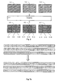
- the initial symbol of the BDU of rank j is mapped within the D-PDU of rank j while in the second and third embodiments, it is always mapped in the first D-BDU.
- Fig. 7a illustrates the first embodiment
- Fig. 7b the second one
- Fig. 7c the third one.
- the embodiments of the invention use a direct allocation where first D-BDU is allocated to the first D-PRB, the second D-BDU to the second D-PRB and so on.
- the symbols of each D-BDU can be mapped within the 2D-array of the allocated D-PRB according to any law.
- the number of D-PRBs can be set at any value L where L ⁇ N D-PRB even greater than R the maximum number of available positions within a PRB. This provides an additional flexibility but in this case, all BDUs are not mapped in all D-PRBs, thus leading to an unequal diversity gain. As long as L is lower than R , then all BDUs occupy some positions within all D-PRBs, but not necessarily the same number.
- the D-BDU contains more symbols to be mapped than available positions within the D-PRB. Some symbols have to be punctured. This is always the case when S is chosen greater than R-N FSmin .
- the D-BDU contains less symbols to be mapped than available positions within the D-PRB, thus leaving unused positions. These positions can be set to a void value or used to carry on other kind of traffic. This is always the case when S is chosen lower than R-N FSmax.
- the D-BDU contains exactly the same number of symbols to be mapped than available positions within the D-PRB. No puncturing is needed and no void position is generated.
- the number of forbidden symbols is the same in all D-PRBs but do not occupy the same positions.
- the first one consists in mapping D-BDUs just as if all D-PRBs share the same pattern of forbidden symbols and simply puncturing symbols that shall be mapped onto forbidden ones. Then, all D-BDUs still occupy all the positions such as in a L-PRB, but some BDUs are punctured and others not possibly leading to different level of performance.
- a second solution is to map symbols onto available positions using the same PRB mapping law. The limitation of this approach is that all D-BDUs do not occupy any more the same positions.
- This first solution leads to the puncturing of the fourth symbol, referenced with a 'P', which would have been mapped on a forbidden symbol, while the second position of the D-PRB, marked as 'V' is void.
- the second solution is illustrated by D-PRBs 9.21, 9.22 and 9.23. One can see that all available positions are used at the price of a slightly different mapping for D-PRB 9.22.
- the third solution is illustrated by D-PRBs 9.31, 9.32 and 9.33. keeping globally the same mapping as the first solution but mapping the fourth symbol to the void position instead of puncturing it.
- the same procedure can be applied taking for N FSmax the maximum number of forbidden positions in a D-PRB. Then, the occurrence of puncturing or leaving free some positions will occur not in all D-PRBs but just in some D-PRBs depending on the effective number of forbidden positions for each particular D-PRB.
- the proposed method can be easily modified to support an efficient mapping of MIMO encoded symbols where it is required to benefit from the same channel conditions for a given number of symbols. For instance, in the case of the Alamouti scheme, it is very important to keep the two elements of each pair adjacent within the D-PRBs. This can be achieved by multiplexing the modulation symbols of BDUs, with an even value of S, and then applying a snake either in time or frequency. More, generally the proposed invention can be applied to map groups of symbols of any size as required by specific transmission schemes.
- An advantage of the proposed invention is to maintain a regularity within the symbols mapped in all D-PRBs even if the PRB structure is not regular itself. This is due to the fact that multiplexing of streams is performed independently of the mapping of the data. This greatly facilitates the implementation avoiding uncessary testing to determine the position of each stream's symbols.
- the number of available symbols S is set as or below to the total number of symbols in a D-PRB reduced by the common number of forbidden symbols.
- the number of D-PRBs is set to L possibly as a sub-multiple of S .
- Each D-BDU is described as an array of symbols according to a law that covers all the positions, only once, of a D-PRB at the exception of forbidden symbols. The law is potentially different within each D-PRB. Data streams are segmented into packets of S symbols, the BDUs.
- Mapping is applied in D-PRBs with multiplexing of streams according to the laws mentioned above and mapped within the D-PRB following the path described by the selected law. When meeting additional forbidden symbols, the corresponding data is punctured. Remaining positions are left void and used for other purpose.
- the key of the proposed technique is that if all D-BDUs are mapped within D-PRBs according to the same law and if D-PRBs share the same pattern of forbidden positions, then all distributed BDUs globally occupy the same set of positions within D-PRBs which are the same as in a localized PRB with the same mapping. As the size of localized and distributed PRB is the same, it is possible to switch from distributed to localized mode depending on the channel conditions. This also avoids the system handling two different payload sizes depending on the allocation mode. The impact of the error on the channel estimation achieved from scattered pilots is also equally spread among the different streams.
- the scheme is also compatible with the simplified signaling approach using, for example, the table based solution.
- all D-PRBs benefit from a inherent frequency diversity due to the fact that all symbols corresponding to a specific stream are mapped both in time and frequency. It allows spreading data from different streams on several physical resource blocks in a way where, within a physical resource block, each sub-carrier carries on data from different streams and during each symbol time, data from different streams are transmitted. It is required to indicate the position of the D-PRBs if it is dynamic and the mapping law within each PRB. If the mapping law is the same within all D-PRBs and position of forbidden symbols is the same, then all streams occupy all the positions of a D-PRB, at the exception of punctured symbols, leading to an even degradation due to channel estimation for all streams and a simplified implementation.
- One advantage of the proposed invention lies in its low complexity in terms of implementation especially for systems that support localized transmission.
- data are typically provided to the physical layer as PDUs to be transmitted over a TTI, where a PDU is allocated a given number of VRBs.
- a typical approach is to encode the PDUs and to store over each transmission interval the resulting symbols into a memory that is organised as a bank of smaller memories corresponding to the number of VRBs within the transmission interval. This operation corresponds to the segmentation of the PDUs into BDUs.
- a key function in an OFDM system is performed by the framing module that builds the OFDM multiplex to be modulated over each symbol duration.
- the OFDM multiplex and thus the PRBs are often built OFDM symbol by OFDM symbol and within each OFDM symbol going through sub-carriers from the left to the right (increasing or decreasing frequencies).
- One issue is to achieve the mapping of BDUs inside the PRBs.
- the mapping is simply a way of covering all available positions for data in a PRB in order to benefit for example of some stationnarity of the channel. It can also be a solution for spreading the data within a PRB in order to maximise diversity.
- This operation consists in mapping the content of a one-dimensional (1D) array, i.e. the BDU, into the PRB that is a 2D array. Dealing with implementation, the mapping can be applied in different ways.
- a first one is to store the content of the BDU in a 2D array corresponding to the PRB structure according to the mapping law. Then, with a latency of one transmission interval, the OFDM symbols can be built accessing the 2D array by rows for each new OFDM symbol.
- the PRB can be viewed as a 1D array which is the concatenation of 1D arrays obtained by slicing the PRB in the time domain. This is described as a flattened PRBs.
- the mapping can be viewed as an interleaving law between two 1D arrays.
- the mapping can simply be achieved using a table (typically a ROM) that stores for each position of the flattened PRB the address of the BDU sample that shall be mapped onto that position.
- a table typically a ROM
- This approach allows applying a 2D mapping without having to first build the PRBs with the BDUs before actual transmission.
- the PRB can be build on an OFDM symbol by OFDM symbol basis thus reducing the latency and the required amount of memory.
- a simple approach consists in applying the invention as a two-step procedure.
- the DBUs corresponding to distributed streams are first multiplexed together and the resulting D-BDUs can then be mapped into D-PRBs according to any mapping law.
- the framing module can build the OFDM symbols just as for localized traffic.
- a basic approach is to perform the dual operation. But this requires to store the data associated to all D-PRBs to then perform the de-mutiplexing operation.
- the de-framing module is able to perform the extraction of the data only for the selected stream (one or more BDUs) on an OFDM symbol by OFDM symbol basis.
- the receiver must perform the demapping of the PRB. This can be done by simply storing in a ROM the address in the corresponding BDU of each symbol in the PRB. Then, when accessing the symbols over each sub-band and each OFDM period, the receiver can directly stores the symbols in the corresponding BDU bank at the right position. A procedure of the same kind can be applied for distributed traffic. Let's first consider the PRB corresponding to the VRB to be extracted. In this PRB with the first multiplexing approach, the stream occupies the first position in the PRB according to selected mapping law. It also occupies all positions N D-PRB apart in the PRB going through the PRB positions according to the selected mapping law.
- the receiver is able to know the position in the BDU of each PRB symbol. What is needed in the case of distributed traffic is to determine if the symbol is associated to the stream to be extracted. By simply dividing the position in the D-BDU (content of the mapping ROM) of the sample modulo the number of D-PRBs, all symbols for which the result is zero is associated to the stream to be extracted. Then, the de-framing stores the corresponding sample at the correct position in the corresponding BDU. This operation can be done for all the data symbols in the D-PRB on an OFDM symbol basis. The same procedure can be applied to the other D-PRBs.
- the first symbol is stored in the first position of the second D-PRB, the second one into the second position in the following D-PRB and so one.
- the user In each D-PRB, the user always occupies all positions N D-PRB apart in the PRB going through the PRB positions according to the selected mapping law but with a specific offset depending on the rank of the D-PRB among all D-PRBs. In these D-PRBs, the selection of the correct symbols is done looking at positions for which the result of the modulo division gives no more zero but the offset associated to the D-PRB.
- This implementation is even simpler when data are mapped the same way in all D-PRBs according to the first multiplexing law and a linear mapping in frequency.
- the stream allocated to the VRB corresponding for example to the second D-PRB occupies the first position in this D-PRB, the second position in the following D-PRB and so on modulo the number of D-PRBs.
- the mapping can therefore be applied just as for localized PRB but shifting to the next D-PRB for each new symbol to be mapped, this for the number of available data positions in each slice of a PRB.
- the stream multiplexing and the mapping are achieved altogether.
- the mapping and framing can also be achieved on a D-PRB basis, i.e. mapping each time slice of each D-PRB in one pass. This can be done accessing linearly the BDUs of the streams to be multiplexed but shifting of one BDU for each new symbol to be mapped.
- a similar procedure can be applied at the receiving side.
- the receiver reads the first symbol in this D-PRB, then reads the second symbol not in the same PRB such as for localized traffic, but in the second D-PRB and so on for the number of available positions for data in the first slice of a PRB. Then, the same procedure can be applied for the second OFDM symbol and so on.
- the invention also permits to mitigate inter-cell interference in cellular networks.
- signals from neighbouring cells interfere with each other.
- the mapping of distributed transmissions is the same in all cells, there may be cases in which the inter-cell interference is not enough random. For instance, if same PRBs are allocated to distributed traffic in all cells and the mapping of D-VRBs on these PRBs is done the same way, one D-VRB is interfered by a single D-VRB of a neighbouring cell. If the interfering D-VRB is not allocated, the interference is null, if the interfering D-VRB is received with low power, the interference has low power and if the interfering D-VRB is received with high power, the interference has high power. There is a strong lack of diversity.
- the interfering power is averaged over the received power of many D-VRBs.
- the diversity is increased and all D-VRBs of the interfered cell experience an average interference power.
- the inter-cell interference is randomized and thus averaged over D-VRBs.
- the mapping of distributed transmissions may advantageously be varied from one cell to another.
- a general way is to add frequency hopping after the mapping, i.e., to permute the data symbols after mapping in a way which is specific to the cell and can be determined for example from the cell identity (ID or cell signature).
- the proposed mapping can be modified by introducing a parameter s , which is cell-specific.
- a parameter s which is cell-specific.
- the first data is always transmitted on the fisrt PRB but the second data is transmitted in a consecutive PRB with a shift of two PRBs modulo the number of D-PRBs. It randomizes the inter-cell interference by a straightforward change in the mapping procedure.
- s is an cell-specific integer such that 1 ⁇ s ⁇ L .
- the 3GPP consortium is currently working on the evolution of the 3GPP radio-access technology as part of the Long Term Evolution (LTE) work item [www.3gpp.com].
- LTE Long Term Evolution
- the goal is to define a high-data-rate, low-latency and packet-optimized radio-access technology suitable for the future generation of radio-mobile cellular systems.
- the OFDMA technique has been selected as a candidate for downlink transmission.
- Several combinations are contemplated in terms of duplex scheme and frame format. We consider here the FDD option with no-coexistence issue where data is transmitted over 10 ms frames made of 20 sub-frames where each 0.5 ms sub-frame is itself composed of 7 OFDM symbols.
- a particularity of the LTE system is the support of different channel bandwidths to allow for a better use of the spectrum resources that appear to be fragmented in some areas.
- Each base station may operate in 1.25, 2.5, 5, 10, 15 or 20 MHz channels.
- Each user equipment (UE) shall be able to operate by default in 20 MHz channels and shall adapt automatically to the base station bandwidth it is connected to.
- the PRBs can be dynamically allocated to streams either in localized or distributed mode.
- the present invention can therefore be applied to the LTE system.
- the flexibility of the proposed invention is particularly well suited to the LTE system where the number of PRBs goes from 6 for the 1.25 MHz bandwidth to 100 in 20 MHz channels.
- PRBs may carry at least two kinds of forbidden symbols, reference symbols and signaling symbols.
- the number of reference symbols depends on the number of transmit antennas with a minimum number of 4 occupied symbols per PRB for one transmit antenna.
- the position of the reference symbols is the same in all the PRBs within a sub-frame.
- all distributed UEs occupy all the positions such as in a localized PRB with the corresponding advantages.
- the present invention provides a great flexibility for the actual implementation of the distributed transmission.
- Fig. 10 displays the functional diagram of a particular embodiment of the invention.
- the BDUs to be distributed 10.2 are multiplexed together according the selected law in the module 10.3.
- data are manipulated simply as one-dimension streams without any relation with the actual mapping of data onto the OFDM sub-frame.
- This module 10.3 provides L BDUs of data corresponding to the L distributed PRBs in the multiplex. These BDUs can then be manipulated just localized traffic.
- the streams corresponding to localized 10.1 and distributed PRB can therefore be multiplexed according to any appropriate law by the module 10.4.
- the different BDUs can then be organised, by the module 10.5, as two-dimensional arrays taking into account the PRB structure according to any mapping law.
- the content of the resulting arrays can then be read by the framing module 10.6 that builds the OFDM multiplex associated to each OFDM symbol of the frame according to the appropriate frame format.
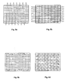
- Fig. 11 depicts an application of the proposed scheme in the case of the 2.5 MHz bandwidth, thus with 12 PRBs in the channel. It is supposed that the system supports only one transmit antenna.
- Distributed streams are mapped onto 5 PRBs according to the same format, namely the first multiplexing law combined with a 2D mapping linear in frequency. It is supposed that the position of the D-PRBs can be modified on a sub-frame basis with a signalling achieved according to the table based approach. For simplification purpose, it is supposed that signalling is transmitted outside PRBs and is reduced to one bit indicating whether the PRB is distributed or not and an UE identifier.
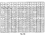
- the signalling table entry of rank i provides the identity of the UE that is allocated to the PRB of the same rank.
- the rank of the UE identifier within the L distributed PRBs indicate on which D-PRB the corresponding UE is mapped onto the first available position.
- Fig. 11-a depicts an example of content of the signalling table. As shown on Fig. 11-a , PRBs numbers 0, 3, 5, 9 and 11 are devoted to distributed traffic, signalled on the table by the first information set to 1. The remaining PRBs arc devoted to localized traffic, signalled on the table by the first information set to 0. The second information gives the reference of the stream that is allocated to the PRB.
- PRBs numbers 0, 3, 5, 9 and 11 are devoted to distributed traffic, signalled on the table by the first information set to 1.
- the remaining PRBs arc devoted to localized traffic, signalled on the table by the first information set to 0.
- the second information gives the reference of the stream that is allocated to the PRB.
- 11b, 11c, 11d , 11e and 11f display the result of the mapping within distributed PRBs for the 5 allocated streams where symbols marked as "P" are forbidden pilot symbols and where the other symbols are marked whith the same convention as above indicating the index within the source BDU and the index of the BDU.
- the allocation of the signalling is not yet clearly defined in the LTE but it shall be multiplexed with data in time over at most the first three OFDM symbols over each TTI duration (2 consecutive sub-frames).
- the main difference with reference symbols is that the number of symbols dedicated to signalling may not be the same in all distributed PRBs.
- Fig. 12 depicts an example of application of the proposed method taking into account the transmission of signalling in addition to reference symbols.
- distributed PRBs include signaling symbols, referenced as "S" on the figure, inserted in the first OFDM symbols of the PRBs.
- Fig. 12 illustrates a situation where all the PRBs do not contain the same number of signaling symbols.
- the PRBs contain signaling in the first two OFDM symbols of each TTI corresponding to the first two lines of the four PRBs illustrated Fig. 12a , 12b , 12c and 12d .
- the PRB of Fig. 12b has 3 extra signaling symbols inserted on the 3 first sub-carrier positions in the third OFDM symbol.
- Fig. 13 presents a general architecture of an embodiment of a transmission device 13.1 able to set up the described methods.
- the transmission device 13.1 is, in a variant, implemented under the form of one or several dedicated integrated circuits which execute the same operations as the one executed by the processor 13.2 as disclosed hereinafter.
- This device comprises a radio module 13.3 to receive and transmit signals. Data to be transmited are generated by the processor 13.2 which is able to execute programs implementing the various described methods. These programes could be stored in a read only memory, ROM, 13.5 or in a random access memory 13.4.
- ROM read only memory
- ROM read only memory
- ROM read only memory
- D-BDUs D-BDUs
- These modules are linked by a bus 13.6 which allows communication between the different modules.
- the radio module 13.3 is controlled by the processor 13.2.
Landscapes
- Engineering & Computer Science (AREA)
- Signal Processing (AREA)
- Computer Networks & Wireless Communication (AREA)
- Quality & Reliability (AREA)
- Mobile Radio Communication Systems (AREA)
Priority Applications (4)
| Application Number | Priority Date | Filing Date | Title |
|---|---|---|---|
| EP07002520A EP1965536A1 (fr) | 2007-02-06 | 2007-02-06 | Procédé de transmission de données dans un système de transmissions multiporteuses et dispositif de mise en place du procédé |
| JP2008019074A JP2008228279A (ja) | 2007-02-06 | 2008-01-30 | マルチキャリアベース伝送システムにおけるデータ伝送方法及びデータ伝送デバイス |
| US12/025,386 US8249043B2 (en) | 2007-02-06 | 2008-02-04 | Method of data transmission in a multi-carrier based transmission system and device implementing the method |
| CN200810080714.2A CN101242257B (zh) | 2007-02-06 | 2008-02-05 | 基于多载波的传输系统中的数据传输的方法及装置 |
Applications Claiming Priority (1)
| Application Number | Priority Date | Filing Date | Title |
|---|---|---|---|
| EP07002520A EP1965536A1 (fr) | 2007-02-06 | 2007-02-06 | Procédé de transmission de données dans un système de transmissions multiporteuses et dispositif de mise en place du procédé |
Publications (1)
| Publication Number | Publication Date |
|---|---|
| EP1965536A1 true EP1965536A1 (fr) | 2008-09-03 |
Family
ID=38325351
Family Applications (1)
| Application Number | Title | Priority Date | Filing Date |
|---|---|---|---|
| EP07002520A Withdrawn EP1965536A1 (fr) | 2007-02-06 | 2007-02-06 | Procédé de transmission de données dans un système de transmissions multiporteuses et dispositif de mise en place du procédé |
Country Status (4)
| Country | Link |
|---|---|
| US (1) | US8249043B2 (fr) |
| EP (1) | EP1965536A1 (fr) |
| JP (1) | JP2008228279A (fr) |
| CN (1) | CN101242257B (fr) |
Cited By (3)
| Publication number | Priority date | Publication date | Assignee | Title |
|---|---|---|---|---|
| WO2010087896A1 (fr) * | 2009-01-28 | 2010-08-05 | Qualcomm Incorporated | Saut de fréquence dans un réseau de communication sans fil |
| EP2352267A1 (fr) * | 2008-11-06 | 2011-08-03 | ZTE Corporation | Procédé de mappage de cellules de ressources |
| US20210136796A1 (en) * | 2008-01-07 | 2021-05-06 | Optis Cellular Technology, Llc | Method and apparatus for determining allocation of communication resources |
Families Citing this family (17)
| Publication number | Priority date | Publication date | Assignee | Title |
|---|---|---|---|---|
| KR101341501B1 (ko) * | 2007-05-29 | 2013-12-16 | 엘지전자 주식회사 | 제어 정보 전송 방법 |
| CN103401642B (zh) * | 2007-06-19 | 2016-06-29 | 松下电器(美国)知识产权公司 | 移动站装置、数据发送方法、数据接收方法以及集成电路 |
| KR100904433B1 (ko) * | 2008-01-07 | 2009-06-24 | 엘지전자 주식회사 | 분산형 가상자원블록 스케쥴링 방법 |
| KR100925441B1 (ko) * | 2008-01-07 | 2009-11-06 | 엘지전자 주식회사 | 분산형 가상자원블록 스케쥴링 방법 |
| ES2711802T3 (es) * | 2008-01-07 | 2019-05-07 | Optis Cellular Tech Llc | Procedimiento para planificar bloques de recursos virtuales distribuidos |
| WO2009107985A1 (fr) | 2008-02-28 | 2009-09-03 | Lg Electronics Inc. | Procédé de multiplexage de données et d’information de commande |
| US8305974B2 (en) * | 2008-04-09 | 2012-11-06 | Nokia Siemens Networks Oy | Method, apparatus and computer program for permutation and subchannelization |
| KR101449766B1 (ko) * | 2008-04-23 | 2014-10-14 | 엘지전자 주식회사 | Tdd 방식에 따른 통신 방법 |
| KR101565417B1 (ko) * | 2008-08-08 | 2015-11-03 | 엘지전자 주식회사 | 다중 주파수 대역 시스템에서의 자원 할당하는 방법 및 장치 |
| EP2424143A1 (fr) * | 2009-04-24 | 2012-02-29 | Panasonic Corporation | Dispositif de communication sans fil et procédé de communication sans fil |
| EP2432148B1 (fr) | 2009-05-13 | 2019-07-03 | Panasonic Intellectual Property Corporation of America | Dispositif de communication radio et procédé de communication radio |
| CN102056296B (zh) * | 2009-10-30 | 2016-03-30 | 索尼株式会社 | 通信网络中的资源分配方法和装置 |
| US9131395B2 (en) * | 2010-09-08 | 2015-09-08 | Broadcom Corporation | Acknowledgment and/or receiver recovery mechanisms for scheduled responses within multiple user, multiple access, and/or MIMO wireless communications |
| CN103796313B (zh) * | 2012-11-01 | 2018-02-09 | 中兴通讯股份有限公司 | 配置增强物理下行控制信道资源集合的方法和装置 |
| CN105453467B (zh) * | 2013-10-18 | 2018-12-25 | 华为技术有限公司 | 无线通信系统中的发送和接收方法及设备 |
| WO2017150447A1 (fr) * | 2016-02-29 | 2017-09-08 | 株式会社Nttドコモ | Terminal utilisateur, station de base radio et procédé de radiocommunication |
| WO2017164222A1 (fr) * | 2016-03-25 | 2017-09-28 | 株式会社Nttドコモ | Terminal d'utilisateur, station de base sans fil, et procédé de communication sans fil |
Citations (2)
| Publication number | Priority date | Publication date | Assignee | Title |
|---|---|---|---|---|
| EP1045522A1 (fr) * | 1999-04-07 | 2000-10-18 | Mitsubishi Electric Telecom Europe | Procédé et dispositif pour entrelacement de canal et multiplexage |
| US6870826B1 (en) * | 1999-05-17 | 2005-03-22 | Mitsubishi Denki Kabushiki Kaisha | Multicarrier transfer system and multicarrier modulation method |
Family Cites Families (3)
| Publication number | Priority date | Publication date | Assignee | Title |
|---|---|---|---|---|
| US6788710B1 (en) * | 1998-03-19 | 2004-09-07 | Thomson Licensing S.A. | Auxiliary data insertion in a transport datastream |
| EP1241824A1 (fr) * | 2001-03-14 | 2002-09-18 | TELEFONAKTIEBOLAGET LM ERICSSON (publ) | Procédé de multiplexage dans un système multiporteur à transmission en diversité |
| US7221680B2 (en) * | 2003-09-02 | 2007-05-22 | Qualcomm Incorporated | Multiplexing and transmission of multiple data streams in a wireless multi-carrier communication system |
-
2007
- 2007-02-06 EP EP07002520A patent/EP1965536A1/fr not_active Withdrawn
-
2008
- 2008-01-30 JP JP2008019074A patent/JP2008228279A/ja active Pending
- 2008-02-04 US US12/025,386 patent/US8249043B2/en not_active Expired - Fee Related
- 2008-02-05 CN CN200810080714.2A patent/CN101242257B/zh not_active Expired - Fee Related
Patent Citations (2)
| Publication number | Priority date | Publication date | Assignee | Title |
|---|---|---|---|---|
| EP1045522A1 (fr) * | 1999-04-07 | 2000-10-18 | Mitsubishi Electric Telecom Europe | Procédé et dispositif pour entrelacement de canal et multiplexage |
| US6870826B1 (en) * | 1999-05-17 | 2005-03-22 | Mitsubishi Denki Kabushiki Kaisha | Multicarrier transfer system and multicarrier modulation method |
Non-Patent Citations (2)
| Title |
|---|
| ERICSSON: "E-UTRA DL - Localized and distributed transmission", TSG-RAN WG1 LTE AD HOC. HELSINKI, FINLAND, JANUARY 23-25, 2006. R1-060095, 23 January 2006 (2006-01-23), pages 1 - 3, XP002446540 * |
| ERICSSON: "E-UTRA DL multiplexing - Multiplexing of reference signals, L1/L2 control signaling, and shared channel", TSG-RAN WG1 LTE AD HOC. HELSINKI, FINLAND, JANUARY 23-25, 2006. R1-060097, 23 January 2006 (2006-01-23), pages 1 - 2, XP002446541 * |
Cited By (6)
| Publication number | Priority date | Publication date | Assignee | Title |
|---|---|---|---|---|
| US20210136796A1 (en) * | 2008-01-07 | 2021-05-06 | Optis Cellular Technology, Llc | Method and apparatus for determining allocation of communication resources |
| EP2352267A1 (fr) * | 2008-11-06 | 2011-08-03 | ZTE Corporation | Procédé de mappage de cellules de ressources |
| EP2352267A4 (fr) * | 2008-11-06 | 2014-02-12 | Zte Corp | Procédé de mappage de cellules de ressources |
| WO2010087896A1 (fr) * | 2009-01-28 | 2010-08-05 | Qualcomm Incorporated | Saut de fréquence dans un réseau de communication sans fil |
| KR101396298B1 (ko) | 2009-01-28 | 2014-05-22 | 퀄컴 인코포레이티드 | 무선 통신 네트워크에서 주파수 홉핑 |
| US9374131B2 (en) | 2009-01-28 | 2016-06-21 | Qualcomm Incorporated | Frequency hopping in a wireless communication network |
Also Published As
| Publication number | Publication date |
|---|---|
| US20080187005A1 (en) | 2008-08-07 |
| JP2008228279A (ja) | 2008-09-25 |
| CN101242257A (zh) | 2008-08-13 |
| CN101242257B (zh) | 2013-10-30 |
| US8249043B2 (en) | 2012-08-21 |
Similar Documents
| Publication | Publication Date | Title |
|---|---|---|
| US8249043B2 (en) | Method of data transmission in a multi-carrier based transmission system and device implementing the method | |
| JP7341300B2 (ja) | 通信システム及び通信方法 | |
| US11252729B2 (en) | Communication device and communication method | |
| CN101779432B (zh) | 用于无线通信的方法和装置 | |
| KR101362976B1 (ko) | 기지국 및 송신방법 | |
| WO2006011524A1 (fr) | Dispositif de transmission radio et dispositif de reception radio |
Legal Events
| Date | Code | Title | Description |
|---|---|---|---|
| PUAI | Public reference made under article 153(3) epc to a published international application that has entered the european phase |
Free format text: ORIGINAL CODE: 0009012 |
|
| AK | Designated contracting states |
Kind code of ref document: A1 Designated state(s): AT BE BG CH CY CZ DE DK EE ES FI FR GB GR HU IE IS IT LI LT LU LV MC NL PL PT RO SE SI SK TR |
|
| AX | Request for extension of the european patent |
Extension state: AL BA HR MK RS |
|
| 17P | Request for examination filed |
Effective date: 20081024 |
|
| 17Q | First examination report despatched |
Effective date: 20081215 |
|
| RAP1 | Party data changed (applicant data changed or rights of an application transferred) |
Owner name: MITSUBISHI DENKI KABUSHIKI KAISHA Owner name: MITSUBISHI ELECTRIC R&D CENTRE EUROPE B.V. |
|
| AKX | Designation fees paid |
Designated state(s): AT BE BG CH CY CZ DE DK EE ES FI FR GB GR HU IE IS IT LI LT LU LV MC NL PL PT RO SE SI SK TR |
|
| STAA | Information on the status of an ep patent application or granted ep patent |
Free format text: STATUS: THE APPLICATION IS DEEMED TO BE WITHDRAWN |
|
| 18D | Application deemed to be withdrawn |
Effective date: 20150901 |