EP1965304A1 - Storage system - Google Patents
Storage system Download PDFInfo
- Publication number
- EP1965304A1 EP1965304A1 EP08008293A EP08008293A EP1965304A1 EP 1965304 A1 EP1965304 A1 EP 1965304A1 EP 08008293 A EP08008293 A EP 08008293A EP 08008293 A EP08008293 A EP 08008293A EP 1965304 A1 EP1965304 A1 EP 1965304A1
- Authority
- EP
- European Patent Office
- Prior art keywords
- partition
- size
- storage device
- storage system
- cache memory
- Prior art date
- Legal status (The legal status is an assumption and is not a legal conclusion. Google has not performed a legal analysis and makes no representation as to the accuracy of the status listed.)
- Granted
Links
Images


Classifications
-
- G—PHYSICS
- G06—COMPUTING; CALCULATING OR COUNTING
- G06F—ELECTRIC DIGITAL DATA PROCESSING
- G06F12/00—Accessing, addressing or allocating within memory systems or architectures
- G06F12/02—Addressing or allocation; Relocation
- G06F12/08—Addressing or allocation; Relocation in hierarchically structured memory systems, e.g. virtual memory systems
- G06F12/0802—Addressing of a memory level in which the access to the desired data or data block requires associative addressing means, e.g. caches
- G06F12/0875—Addressing of a memory level in which the access to the desired data or data block requires associative addressing means, e.g. caches with dedicated cache, e.g. instruction or stack
-
- G—PHYSICS
- G06—COMPUTING; CALCULATING OR COUNTING
- G06F—ELECTRIC DIGITAL DATA PROCESSING
- G06F12/00—Accessing, addressing or allocating within memory systems or architectures
- G06F12/02—Addressing or allocation; Relocation
- G06F12/08—Addressing or allocation; Relocation in hierarchically structured memory systems, e.g. virtual memory systems
- G06F12/0802—Addressing of a memory level in which the access to the desired data or data block requires associative addressing means, e.g. caches
- G06F12/0806—Multiuser, multiprocessor or multiprocessing cache systems
- G06F12/084—Multiuser, multiprocessor or multiprocessing cache systems with a shared cache
-
- G—PHYSICS
- G06—COMPUTING; CALCULATING OR COUNTING
- G06F—ELECTRIC DIGITAL DATA PROCESSING
- G06F12/00—Accessing, addressing or allocating within memory systems or architectures
- G06F12/02—Addressing or allocation; Relocation
- G06F12/08—Addressing or allocation; Relocation in hierarchically structured memory systems, e.g. virtual memory systems
- G06F12/0802—Addressing of a memory level in which the access to the desired data or data block requires associative addressing means, e.g. caches
- G06F12/0866—Addressing of a memory level in which the access to the desired data or data block requires associative addressing means, e.g. caches for peripheral storage systems, e.g. disk cache
- G06F12/0873—Mapping of cache memory to specific storage devices or parts thereof
-
- G—PHYSICS
- G06—COMPUTING; CALCULATING OR COUNTING
- G06F—ELECTRIC DIGITAL DATA PROCESSING
- G06F12/00—Accessing, addressing or allocating within memory systems or architectures
- G06F12/02—Addressing or allocation; Relocation
- G06F12/08—Addressing or allocation; Relocation in hierarchically structured memory systems, e.g. virtual memory systems
- G06F12/12—Replacement control
- G06F12/121—Replacement control using replacement algorithms
-
- G—PHYSICS
- G06—COMPUTING; CALCULATING OR COUNTING
- G06F—ELECTRIC DIGITAL DATA PROCESSING
- G06F2212/00—Indexing scheme relating to accessing, addressing or allocation within memory systems or architectures
- G06F2212/26—Using a specific storage system architecture
- G06F2212/261—Storage comprising a plurality of storage devices
-
- G—PHYSICS
- G06—COMPUTING; CALCULATING OR COUNTING
- G06F—ELECTRIC DIGITAL DATA PROCESSING
- G06F2212/00—Indexing scheme relating to accessing, addressing or allocation within memory systems or architectures
- G06F2212/28—Using a specific disk cache architecture
- G06F2212/282—Partitioned cache
Abstract
Description
- This application relates to and claims priority from Japanese Patent Application No.
2005-037347, filed on February 15, 2005 - The present invention relates to a storage system which can optimize performance tuning of a cache memory for each of a plurality of application programs.
- Recently, storage consolidation where storages dispersed in each server are consolidated in a single place and connected to servers via a storage-dedicated network such as a SAN (Storage Area Network) has been widely used. As an operation pattern of the storage consolidation, common use of a storage system by a plurality of application programs or contents has been increasing. The storage system is configured with, for example, a disk array device and the like. A disk array device is configured by disposing numbers of disk drives in an array, and is constructed on the basis of, for example, RAID (Redundant Array of Independent Inexpensive Disks). On a physical storage region provided by the group of disk drives, at least one or more logical volumes are formed that are provided to a host device. The host device can read and write data for the logical volumes by issuing a write command or read command to the storage system.
- In this type of storage system, a cache memory for temporarily storing write data for writing data into a disk drive or read data for reading data from the disk drive is mounted, to realize high speed I/O processing for the host device (For example, Japanese Patent Application Laid-Open No.
2001-166993 - However, since the I/O characteristics of each application program differ, it is necessary to optimize performance tuning of the cache memory (for example, setting of the segment size, necessity of dual writing (mirror writing) between controllers, etc.) in accordance with the I/O characteristics.
- For example, as with an application program which performs streaming delivery of the contents of an moving image, a still image or the like, for such application program for consecutively processing large quantities of data, it is preferred that the segment size of the cache memory be set large and that the overhead be reduced. On the other hand, for an application program in which a fine access such as a database is issued randomly, it is preferred that the segment size be set small and the overhead be reduced.
- Further, for example, as in an online service in a bank, for an application program in which high reliability is required, it is necessary to duplicate the cache data to securely save the data in case of trouble. On the other hand, as in a temporary simulation such as weather prediction etc. or scientific and engineering calculations, when performing calculation on the basis of source data which is saved using another method, securing the performance of the calculation is often a center of focus rather than securing high reliability by dual writing the data to the cache memory, for saving a half-way calculation result (temporary data or the like).
- In a conventional storage system, performance tuning for judging necessity of segment size settings or of dual writing in accordance with the I/O characteristics for each application program could not be performed, thus in a storage system which is shared by a plurality of application programs, when performing tuning for a cache memory which is optimum to a certain application program, there occurred a problem that the performances of other application programs decrease. For example, when setting the segment size large for an application program which provides a streaming service, the application program such as a database is lowered in the percent of hit rate of the cache memory.
- Moreover, in the storage system which is shared by a plurality of application programs, a resource conflict between the application programs could be generated, thus it is necessary to inhibit the resource conflict to appropriately bring the performance of each application program into action. For example, in the storage system which is shared by a plurality of application programs having different loads, more writing is performed from an application program having a high load, thus the cache memory is filled with the data of the high load application program, and a resource conflict with other application program may be generated.
- Such a resource conflict could be generated not only between a plurality of application programs having different I/O characteristics but also between a plurality of disk drives having different performance characteristics. For example, in a storage system which has mixed loads of a fiber channel disk drive and ATA (Advanced Technology Attachment) disk drive, it takes longer time for access in the ATA disk drive than the fiber channel disk drive, thus the time required in destaging from the cache memory to the ATA disk drive is longer than the time required in destaging from the cache memory to the fiber channel disk drive. Consequently, the time taken for the data of the application program that uses the ATA disk drive to accumulate in the cache memory becomes long by that much, thus the data of the ATA disk drive is accumulated in the cache memory, thereby generating a resource conflict.
- The present invention is contrived in the light of the problems described above, and one of the preferred aims of the present invention is to provide, in a storage system which is shared by a plurality of application programs, a storage system which can optimize performance tuning of a cache memory for each application program.
- Another preferred aim of the present invention is to provide, in a storage system which is shared by a plurality of application programs, a storage system which inhibits performance deterioration caused by a resource conflict of a cache memory between a plurality of application programs having different I/O characteristics or between a plurality of storage devices having different performance characteristics.
- Preferably to solve the above problems, the storage system of an aspect of the present invention comprises a storage device for providing a plurality of logical volumes which can be accessed from a plurality of application programs, a controller for controlling input and output of data to and from the logical volumes in response to input/output requests from the plurality of application programs, and a cache memory for temporarily storing the data input and output to and from the logical volumes, wherein the cache memory is logically divided into a plurality of partitions assigned exclusively for the plurality of logical volumes.
- For each of the plurality of logical volumes, by assigning each of the plurality of partitions exclusively, a resource conflict between the logical volumes assigned exclusively to the respective application programs may be inhibited, whereby performance tuning of an optimum cache memory can be performed.
- Even when the performance characteristics of the storage device are different, by assigning the plurality of partitions exclusively to the plurality of logical volumes respectively, the resource conflict of the cache memory, which is caused by the difference in the performance characteristics of the storage device, may be inhibited, and performance tuning of an optimum cache memory can be performed.
- Preferably, in such a storage system according to the invention, the plurality of application programs are exclusively assigned to the plurality of logical volumes respectively.
- Further, the plurality of partitions may be configured such that the segment size can be independently adjusted and the controller configures the segment by logically associating subsegments which are the constitutional units of the segments of the cache memory, and adjusts the number of subsegments that constitute the segments, thereby independently adjusting the segment size for every partition.
- Preferably, the controller restrains input and output of data to and from the logical volume corresponded to the partition in which the segment size is adjusted, and destages dirty data stored in the partition to the storage device, and thereafter independently adjusts the segment size for every partition.
- In a further embodiment, the controller responds to an input/output request from the application program by means of a write-through system in the course of destaging to the storage device the dirty data stored in the partition in which the segment size is adjusted, and, after destaging is completed, independently adjusts the segment size for every partition.
- The storage system according to the invention may further comprise a management terminal for managing the storage system, wherein the controller independently adjusts the segment size for every partition in response to an instruction from the management terminal.
- In the storage system according to the invention, the plurality of partitions may be configured such that the partition size can be independently adjusted, wherein the controller adjusts the partition size by logically associating the blocks of the cache memory.
- In an embodiment of the storage system according to the invention, the controller restrains input and output of data to and from the logical volume corresponded to the partition in which the partition size is adjusted, and, in the partition in which the partition size is adjusted, destages to the storage device the dirty data stored in the block which is used when changing the partition size, and thereafter moves the block between the plurality of partitions adjusting the partition sizes, thereby independently adjusting the partition size for every partition.
- In the partition in which the partition size is adjusted, the controller may be configured such that it responds to an input/output request from the application program by means of a write-through system in the course of destaging to the storage device the dirty data stored in the block used when changing the partition size, and, after destaging the dirty data stored in the block is completed, moves the block between the plurality of partitions adjusting the partition sizes, thereby independently adjusting the partition size for every partition.
- The storage system according to the invention may further comprise a management terminal for managing the storage system, wherein the controller independently adjusts the partition size for every partition in response to an instruction from the management terminal.
- The storage system according to the invention may further comprise a timer for timing a current time, wherein the controller independently adjusts the partition size for every partition such that the partition size becomes a preset partition size when a time which is timer controlled in advance is reached.
- The storage system according to the invention may further comprise a plurality of cache memories, wherein the plurality of partitions are independently configured such that necessity of dual writing into the plurality of cache memories is set freely, and may further comprise a management terminal for managing the storage system, wherein the controller independently adjusts the necessity of dual writing for every partition in response to an instruction from the management terminal.
- A storage system according to the invention may comprise: a storage device which provides a plurality of logical volumes which can be accessed from a plurality of application programs; a CPU for controlling input and output of data to and from the logical volumes in response to input/output requests from the plurality of application programs; a cache memory for temporarily storing data input to and output from the logical volumes; and a local memory configured so as to be accessed at higher speed than the cache memory and for storing management information of cache data,
wherein the cache memory is logically divided into a plurality of partitions which are exclusively assigned to the plurality of logical volumes respectively, and the CPU manages the cache data by referring to the management information stored in the local memory. - In such a storage system according to the invention, the cache memory stores therein the same management information as the management information stored in the local memory, and the CPU updates the management information stored in both the cache memory and the local memory.
- The cache memory may be a nonvolatile memory.
- In such a storage system according to the invention, when the management information of the local memory is lost due to a power failure, the CPU may restore the lost management information by copying the management information stored in the cache memory to the local memory.
- In such a storage system according to the invention, preferably, the management information of the cache data is information for queue-managing a parent subsegment management block and a child subsegment management block for respectively managing a parent subsegment and a child subsegment which are the constitutional units of subsegments of the cache memory, wherein the parent subsegment management block comprises a parent subsegment address which indicates a position of the parent subsegment in the cache memory, a forward pointer which indicates the parent subsegment management block in the order of oldest to latest accesses, a backward pointer which indicates the parent subsegment management block in the order of latest to oldest accesses, and a child subsegment pointer which indicates a child subsegment management block, and the child subsegment management block comprises a child subsegment address which indicates a position of the child subsegment in the cache memory, and a forward pointer which indicates the child subsegment management block in the order of oldest to latest accesses.
- In the Figures:
-
Fig. 1 is a block diagram which shows a main configuration of a storage system; -
Fig. 2 is an explanatory diagram which shows dual writing of cache data; -
Fig. 3 is a figure which shows a correspondence of each partition to a logical volume; -
Fig. 4 is a figure which shows a correspondence of LUN to a partition number; -
Fig. 5 is a figure which shows an outline in which a resource conflict is inhibited by cache partitioning; -
Fig. 6 shows a logical configuration of each partition; -
Fig. 7 shows a correspondence of a physical configuration of each partition to a logical configuration; -
Fig. 8 is a main configuration diagram of a controller; -
Fig. 9 is a figure which shows a correspondence of a segment to the management information thereof; -
Fig. 10 is a flow chart of a partition size automatic change processing routine; -
Fig. 11 is a flow chart of a partition size manual change processing routine; -
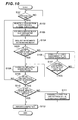
Fig. 12 is a flow chart of a segment size change processing routine; -
Fig. 13 is a flow chart of a partition/LU allocation change processing routine; -
Fig. 14 is an example of a unit screen display; -
Fig. 15 is an example of reference/change screen display of a partition; -
Fig. 16 is an example of display of partition change screen; -
Fig. 17 is an example of display of a setting screen for partition assignment for a logical volume; -
Fig. 18 is an example of display of a partition assignment change screen; -
Fig. 19 is an example of display of a partition specification screen; -
Fig. 20 is a block diagram which shows a main configuration of the storage system; -
Fig. 21 is a block diagram which shows a main configuration of the storage system; -
Fig. 22 is a block diagram which shows a main configuration of the storage system; and -
Fig. 23 is a flow chart for a recovery processing routine in case of a power failure. - Embodiments of the present invention will now be described with reference to each figure. Each embodiment is not to limit the patent claims, and all the characteristics described in the embodiments are not necessarily required for means of solution.
-
Fig. 1 shows a main configuration of the storage system according to the present embodiment. - A
storage system 10 is connected to one or a plurality ofhost devices 60 via acommunication network 50. Thehost device 60 is a server device, personal computer, workstation, main frame, or the like which functions as a higher-level device of thestorage system 10. Thehost device 60 has mounted therein a plurality of applicationprograms AP# 0,AP# 1, ..., AP#N that are operated on an OS (Operating System) 61. A storage resource provided by thestorage system 10 is shared by the plurality of applicationprograms AP# 0,AP# 1, ..., AP#N. - Examples of the
communication network 50 include, for example, a SAN (Storage Area Network), LAN (Local Area Network), Internet, dedicated circuit, public circuit, and the like. When thehost device 60 is connected to thestorage system 10 via a SAN, thehost device 60 requests data input/output by a block which is a data executive unit of thestorage system 10 in accordance with a fiber channel protocol. When thehost device 60 is connected to thestorage system 10 via a LAN, thehost device 60 specifies a file name and requests data input/output, file by file by a protocol such as an NFS (Network File System), iSCSI (internet Small Computer System Interface) or the like. In order for thestorage system 10 to receive a file access request from thehost device 60, it is necessary to load a NAS (Network Attached Storage) function. - The
storage system 10 employs a dual controllerconfiguration comprising controllers disk drives 40 as storage devices provided to the plurality of applicationprograms AP# 0,AP# 1, ..., AP#N. For the disk drives 40, a plurality of disk drives having different performance characteristics, such as, for example, a fiber channel disk drive, serial ATA disk drive, parallel ATA disk drive, SCSI disk drive and the like, or one of these disk drives may be used. Here, "performance characteristics" means, for example, an access speed or the like for the disk drive. - Besides these disk drives, an optical disk, semiconductor memory, magnetic tape, flexible disk or the like may be employed as the storage device.
- The
controller disk drives 40 at a RAID level (0, 1, 5, for example) which is defined by a so called RAID formula. In the RAID formula, the plurality ofdisk drives 40 are managed as a single RAID group. A plurality of logical volumes as an access unit from thehost device 60 are defined in the RAID group. Anidentifier LU# 0,LU# 1, ..., LU#M called "LUN (Logical Unit Number)" is given in each logical volume. - The
controller 20 mainly comprises aCPU 21, CPU/PCI bridge 22, local memory (LM) 23, data transfer control section (D-CTL) 24, cache memory (CM) 25, host I/F control section 26, and drive I/F control section 27. -
CPU 21 is a processor for controlling I/O processing (write access or read access) for the plurality ofdisk drives 40 in response to a data input/output request from thehost device 60. Thecontroller 20 comprises atimer 29, and thus is configured so as to automatically adjust the segment size of thecache memory 25 when a preset time is reached (the detail will be described later). Thelocal memory 23 has stored therein a micro program of theCPU 21. The CPU/PCI bridge 22 connects theCPU 21,local memory 22, and datatransfer control section 24 to one another. Thecache memory 25 is a buffer memory which temporarily stores write data for writing data into thedisk drive 40 or read data obtained by reading from thedisk drive 40. Thecache memory 25 has a backup power and is configured as a nonvolatile memory which prevents loss of cache data even when a power failure occurs in thestorage system 10. - The data
transfer control section 24 connects the CPU/PCI bridge 22,cache memory 25, host I/F control section 26, and drive I/F control section 27 to one another, and controls data transfer between thehost device 60 and thedisk drive 40. Specifically, when a write access from thehost device 60 is made, the datatransfer control section 24 writes the write data received from thehost device 60 via the host I/F control section 26 into thecache memory 25, and thereafter transfers the write data to the drive I/F control section 27 in order to write asynchronously the write data into thedisk drive 40. In addition, when a read access from thehost device 60 is made, the datatransfer control section 24 writes the read data read out from thedisk drive 40 via the drive I/F control section 27 into thecache memory 25, and transfers it to the host I/F control section 26. APCI bus 28 is wired between the datatransfer control section 24 and the CPU/PCI bridge 22. - The host I/
F control section 26 is a controller for controlling an interface with thehost device 60, and has, for example, a function for receiving a block access request from thehost device 60 made by a fiber channel protocol. The drive I/F control section 27 is a controller for controlling an interface with thedisk drive 40, and has, for example, a function for controlling a data input/output request for thedisk drive 40 in accordance with the protocol which controls thedisk drive 40. - The
controller 30 comprises aCPU 31, CPU/PCI bridge 32, local memory (LM) 33, data transfer control section (D-CTL) 34, cache memory (CM) 35, host I/F control section 36, and drive I/F control section 37, and the same configuration as thecontroller 20. Thecontroller 30 comprises atimer 39, and thus is configured so as to automatically adjust the segment size of thecache memory 35 when a preset time is reached (the detail will be described later). - The data transfer
control sections respective controllers control sections disk drive 40 is managed at aRAID level 5, the datatransfer control sections - The
storage system 10 is connected to amanagement terminal 70 for maintaining or managing the system. Data communication is carried out between the both on the basis of a predetermined communication protocol such as fiber channel protocol, TCP/IP, or the like. An operator can perform setting of a logical volume defined in thedisk drive 70, add on or reduce the disk drives 40, change the settings of the RAID configuration (for example, change fromRAID level 5 to RAID level 1), or the like by operating themanagement terminal 70. Moreover, as will be described later, optimum performance tuning of theindividual cache memory 25, 35 (partitioning, partition size setting, segment size setting, dual writing necessity setting, assignment setting or assignment change of the logical volume for a partition, and the like) can be performed for the respective applicationprograms AP# 0,AP# 1, ..., AP#N. - Note that the
management terminal 70 may be embedded inside or attached externally to thestorage system 10. -
Fig. 2 shows an outline of dual writing of the cache data by a dual controller. For the sake of explanatory convenience, in the following explanation thecontroller 20 is sometimes called "CTL# 0", and thecontroller 30 is sometimes called "CTL# 1". TheCTL# 0 andCTL# 1 is each assigned a logical volume which has an authority to access exclusively. For example,CTL# 0 has an authority to accessLU# 0 exclusively, andCTL# 1 has an authority to accessLU# 1 exclusively. With regard to which one of the logicalvolumes LU# 0,LU# 1 is exclusively assigned to which one ofCTL# 0,CTL# 1, each ofCTL# 0,CTL# 1 can figure out their own access authorities by, for example, the setting information on a management information region (seeFig. 8 ) or the like on thecache memory - The
cache memory 25 is divided into a plurality of storage regions P01, P02, P03, and thecache memory 35 is divided into a plurality of storage regions P11, P12, P13. The storage region P01 is a storage region for temporarily storing cache data DATA0 which is written into the logical volume assigned exclusively to CTL#0 (LU# 0, for example), and dual writing setting (mirror-on setting) is conducted in this storage region P01. In other words, the cache data DATA0 written into the storage P01 is also written into the storage region P11 by control ofCTL# 0. The storage region P11 is a storage region for mirroring performed byCTL# 0. - Similarly, the storage region P12 is a storage region for temporarily storing cache data DATA1 which is written into the logical volume assigned exclusively to CTL#1 (
LU# 1, for example), and dual writing setting is conducted in this storage region P12. In other words, the cache data DATA1 written into the storage P12 is also written into the storage region P02 by control ofCTL# 1. The storage region P02 is a storage region for mirroring performed byCTL# 1. - The storage regions P03, P13 are storage regions in which the dual writing settings are not conducted (mirror-off setting).
- Note that the storage regions P01, P02, P11, P12 in which the dual writing settings are applied are called "mirror-on regions" and the storage regions P03, P13 in which the dual writing settings are not applied are called "mirror-off regions".
- Incidentally, the data
transfer control section cache memory controller -
Fig. 3 shows a correspondence of each partition of the cache memory to an application program and logical volume. Each of the storage regions described above (for example, P01) is logically divided into a plurality of partitions (for example,P01# 0,P01# 2, P01#3). The partition is a storage region for storing user data and logically divided on the cache memory, and refers to an individual storage region assigned exclusively to an individual logical volume. The term "partition" can be also called "area", "divided storage region", "divided area", "divided cache" and the like without departing from the scope. In the respective partitions, different logical volumes (for example, logical volumes to avoid a resource conflict)LU# 0,LU# 1, ..., LU#M are exclusively assigned, whereby independent resource management can be performed in thecache memory cache memory disk drive 40 having different performance characteristics, a resource conflict occurred by the difference in the performance characteristics of the logical volumes. - By exclusively assigning a plurality of application
programs AP# 0,AP# 1, ..., AP#N having different I/O characteristics to the respective logicalvolumes LU# 0,LU# 1, ..., LU#M, a resource conflict in thecache memory programs AP# 0,AP# 1, ..., AP#N can be prevented. For example, examples such that the logicalvolume LU# 0 used by a versatile application program to thepartition P01# 0, the logicalvolume LU# 2 used by a database is assigned to thepartition P01# 1, and the logicalvolume LU# 3 used by an application program for streaming is assigned to thepartition P01# 2 are shown. - Further, the storage region P03 as a mirror-off region is divided into
partitions P03# 0,P03# 1, and in the respectivepartitions P03# 0,P03# 1, logicalvolumes LU# 5,LU# 6 used by an application program (HPC) which performs scientific and engineering calculations are assigned. The mirror-off region is used when dual writing is not necessary such as when temporary data is stored as in the case of a half-way calculation result of the scientific and engineering calculations. - Similarly storage regions P02, P11, P12, P13 are logically divided into a plurality of partitions.
- Note that the partition division pattern (the number of partitions, partition size, and partition segment) of the storage region P11 as the mirroring region (copy destination region) of the storage region P01 (copy source region) is same as the partition division pattern of the storage region P01. Similarly, the partition division pattern of the storage region P12 as the mirroring region (copy destination region) of the storage region P02 (copy source region) is same as the partition division pattern of the storage region P12. On the other hand, the partition division patterns of the storage regions P03, P13 as the mirror-off regions do not always have to be the same, and the sizes of the storage regions P03, P13 do not always have to be the same. However, by setting the sizes of the storage regions P03, P13 to be the same, the mirror-on regions can be used efficiently.
- Moreover, setting of necessity judgment for dual writing (mirror-on/mirror-off) can be performed for each partition. If the mirror-off settings are performed, cache data is not necessarily transferred between the data transfer
control sections controllers -
Fig. 4 shows a correspondence of LUN to the number of partitions. This correspondence can be changed accordingly when an operator operates themanagement terminal 70 and instructs thestorage system 10 for an allocation change in the logical volume and the partition (the detail will be described later). -
Fig. 5 shows an outline in which a resource conflict is inhibited by assigning a logical volume to each partition. Cache data DATA2 written and read by the applicationprogram AP# 1 into and out from the logicalvolume LU# 2 is stored in thepartition P01# 1, and cache data DATA3 written and read by the applicationprogram AP# 2 into and out from the logicalvolume LU# 3 is stored in thepartition P01# 2. The applicationprogram AP# 1 is a program which issues fine random accesses to the database and the like, while the applicationprogram AP# 2 is a program such as for streaming to handle consecutive large quantities of data, thus the I/O characteristics of both largely differ. Specifically, the amounts of time that the cache data DATA2, DATA3 stored in eachpartition P01# 1,P01# 2 are different, thus a resource conflict may occur when independent source management is not provided to each partition. - However, by partitioning the cache memory and exclusively assigning a resource of the cache memory which can be used by each application
program AP# 1,AP# 2, the cache data DATA2 of the applicationprogram AP# 1 does not consume the resource of thepartition P01# 2. Similarly, the cache data DATA3 of the applicationprogram AP# 2 does not consume the resource of thepartition P01# 1. Accordingly, the load of a single application program spreads over the entire cache memory, whereby a resource conflict can be prevented from being caused. - Note that even when the performance characteristics of the disk drives configuring the logical
volumes LU# 2,LU# 3, a resource conflict can be inhibited for the same reason. -
Fig. 6 shows a logical configuration of a partition. It illustrates an example in which each storage region divided into four partitions. The partition size of each partition and the segment size are set to optimum values in accordance with the I/O characteristics of the application program. Generally, when setting the segment size large, management information for managing transition from a state of dirty data to clean data is reduced, thus the processing speed increases and the overhead can be reduced. When setting the segment size small, the percent hit rate of the cache memory increases. For example, for the partition used by an application program which consecutively handles large quantities of data for transmitting a moving image or the like, the segment size is set large, and for the partition used by an application program which issues fine random accesses to the database and the like, it is preferred that the segment size be set small. - In an example shown in the same figure, the segment size of the
partition P01# 0 is set to 16 KB (default size), the segment size of thepartition P01# 1 to 4 KB, the segment size of thepartition P02# 0 to 64 KB, and the segment size of thepartition P03# 0 to 512 KB. - Not only for the mirror-on regions (storage regions P01, P02, P11, P12) but for the mirror-off regions (storage regions P03, P13), the partition size and the segment size for each partition are set to optimum values in accordance with the I/O characteristics of the application program.
- As an operation pattern of the
storage system 10, for example, the default settings are affected in advance for the partition size, segment size, necessity judgment of dual writing, and the like for each application program, and when thestorage system 10 judges the types of the application programs, and the partition size, segment size, necessity judgment of dual writing and the like are set on the basis of a set value which is set to default setting with respect to the application program, so that optimum performance tuning can be performed for the cache memory. - The segment size of each partition can be automatically and dynamically changed in its settings without turning off the power and by an input operation of an operator in accordance with a change of the I/O characteristics of the application program. For example, although the segment size of the
partition P01# 0 is set to 16 KB default, this can be dynamically enlarged (changed to 64 KB, for example) or narrowed down (changed to 4 KB, for example) in accordance with a change of the I/O characteristics. Further, the settings of the partition size of each partition can be changed without turning off the power by an input operation of an operator or automatically. For the partition used by an application program which handles large quantities of data, the partition size can be set large, and for the partition used by an application program which handles small quantities of data, the partition size can be set small. - As an example where the
storage system 10 automatically changes settings of the segment size or partition size, theCPUs cache memory -
Fig. 7 shows a correspondence of the physical configuration of each partition to the logical configuration. The cache memory is logically divided into a plurality of partitions by mapping a plurality of blocks (for example,BLK# 0,BLK# 9,BLK# 25, BLK#27) to individual partition (P01# 0, for example). Each block is configured by a plurality of segments SEG. By realizing logical division of the partition by mapping the blocks as above, changing the partition size can respond to mapping change of the blocks, thus the movement of the segment can be kept to the minimum. Supposedly, if the physical configuration and logical configuration are equalized, when changing the partition size, the partition boundaries have to be moved little by little sequentially, and thus large quantities of segments may have to be moved. -
Fig. 8 shows a main configuration of a controller. Since the hardware with the same symbols as those shown inFig. 1 indicate the same hardware, the detailed explanations are omitted. The storage region provided by thecache memory 25 is mainly divided into amanagement information region 25a and auser data region 25b. Theuser data region 25b is a storage region for temporarily storing user data (cache data), and is divided into a plurality of partitions in accordance with the plurality of application programs as described above. In themanagement information region 25a, management information required for managing the user data, e.g. data attribute (read data/write data), a logical address of the user data, which is specified by thehost device 60, information on free areas in the cache memory, information on priority regarding replacement of the cache data, and other information, are stored. -
Fig. 9 shows a correspondence of the segment to a parent subsegment management block and child subsegment management block. In the present embodiment, the segment is configured by a single or a plurality of subsegments, where the segment size is adjusted by adjusting the number of subsegments configuring the segment. The size of the segment is set to a fixed size beforehand. When configuring a segment from a plurality of subsegments, in this segment a subsegment which is accessed first is called "a parent subsegment", and a subsegment which is accessed second onward is called "a child subsegment". When not distinguishing between the parent subsegment and the child subsegment, the segment is simply called "a segment". - In the same figure, subsegments that are accessed are shown by SSEG1 to SSEG8 indicate in the order of the access. When the size of a subsegment is set to 16 KB default, in order to make the segment size 64 KB, it is necessary to configure the segment by collecting four segments. For example, SSEG1 is taken as a parent subsegment and three subsegments SSEG2 to SSEG4 that follow thereafter are taken as child subsegments to relate them to each other logically, whereby one segment can be configured. Similarly, SSEG5 is taken as a parent subsegment and three subsegments SSEG6 to SSEG8 that follow thereafter are taken as child subsegments to associate them to each other logically, whereby one segment can be configured.
- Note that a parent subsegment and child subsegment do not always have to be disposed on the consecutive storage regions, and may be discretely scattered in places.
- A parent
subsegment management block 80 comprises aparent subsegment address 81,forward pointer 82,backward pointer 83,child subsegment pointer 84, and parentsubsegment management information 85. Theparent subsegment address 81 shows a position of a parent subsegment managed by the parentsubsegment management block 80. Theforward pointer 82 indicates the parentsubsegment management block 80 in the order of oldest to latest accesses. Thebackward pointer 83 indicates the parentsubsegment management block 80 in the order of latest to oldest accesses. Thechild subsegment pointer 84 indicates a childsubsegment management block 90. In the parent subsegment management information 85 a status of a parent subsegment (dirty/clean/free) or the like is stored. When dirty data and clean data are mixed in the parent subsegment, the statuses are managed by the bitmap information. - The child
subsegment management block 90 comprises achild subsegment address 91,forward pointer 92, and childsubsegment management information 93. Thechild subsegment address 91 indicates a position of a child subsegment managed by the childsubsegment management block 90. Theforward pointer 92 indicates the childsubsegment management block 90 in the order of oldest to latest accesses. In the childsubsegment management information 93, a status of a child subsegment and the like are stored. When dirty data and clean data are mixed in the child subsegment, the statuses are managed by the bitmap information. - A
forward pointer 101 indicates an end of theforward pointer 81 and thebackward pointer 102 is indicated by thebackward pointer 82. - As above, the parent
subsegment management block 80 and the childsubsegment management block 90 that are queue managed are, when their statuses are dirty data, queue managed, and when their statuses are clean data, are queue managed as clean data. By logically relating the parent subsegment to the plurality of child subsegment to configure a segment, high speed destaging processing can be achieved, since the child subsegments move when a mother subsegment is moved. -
Fig. 10 shows a flow chart of a partition size automatic change processing routine. Some applicationprograms AP# 0,AP# 1, ..., AP#N are required to be operated for 24 hours at any time as usage, and some are increased in the operating rate at a certain period of time. The load is different time to time. In order to appropriately bring the performance of the application program into action, it is preferred that the partition size be changed in accordance with the load fluctuation of each period of time. For example, in the night time when a certain application program is not operated, the partition size that other application program use is increased. - When the partition size automatic change processing routine is called, the
CPU 21 checks whether or not the current time thetimer 29 ticks is equivalent to a timer controlled time (S101). When the current time reaches the timer controlled time (S101; YES), theCPU 21 selects a partition having a partition size larger than the partition size specified beforehand by an operator as a change-from partition, and a partition having a partition size smaller than the partition size specified by the operator as a change-to partition (S102). - For example, suppose that the size of the
partition P01# 0 is set to 10 % of auser data region 25b and the size of thepartition P01# 1 is set to 5 % of theuser data region 25b. In order to change the size of thepartition P01# 1 to 7 %, it is only necessary to move 2-percent block to thepartition P01# 1 from thepartition P01# 0. At this time thepartition P01# 0 is the change-from partition and thepartition P01# 1 is the change-to partition. However, when a plurality of change-from partitions are present, a partition used by the application program having the lowest operating rate may be preferentially selected as the change-from partition at that period of time. - Next, the
CPU 21 secures a block which moves from the change-from partition to the change-to partition, destages the dirty data in this block (S103), and dequeues the parent subsegment management block and child subsegment management block that manage the subsegment inside the block (S104). - Thereafter, the
CPU 21 checks whether or not the segment size of the change-to partition is the smallest size (subsegment size) (S105). When the segment size of the change-to partition is not the smallest size (S105; NO), theCPU 21 reconfigures queue management of the parentsubsegment management block 80 and the childsubsegment management lock 90 such that the child subsegment is connected to the parent subsegment. (S106), repeats this reconfiguration processing the number of the child subsegments (S107), thereby conforming the segment size of the block moving from the change-from partition to the change-to partition to the segment size of the change-to partition. - When the segment size is not the smallest size (S105; NO), or when the process of S106 is completed the number of child subsegment (S107; YES), the
CPU 21 reconfigures queue management of the parentsubsegment management block 80 so that the parent subsegments are connected to each other (S108), and this reconfiguration process is repeated until all the partitions have the specified size (S109). - Next, the
CPU 21 checks whether or not thecache memory 25 is set to mirror-off setting (S110), and, when it is not set to mirror-off setting (S110; NO), sends an instruction to theCPU 31 so as to change the partition size as with the mirror-on region of the cache memory 35 (S111). Accordingly, the partition sizes of the mirror-on regions of thecache memory cache memory 25 is set to mirror-off setting (S110; YES), it is not necessary to change the partition size or the like of thecache memory 35, thus theCPU 21 sends a report of completion to the operator (S112) and leaves the routine. -
Fig. 11 illustrates a flow chart of a partition size manual change processing routine. The operator can operate themanagement terminal 70 to instruct thestorage system 10 to change the partition size. For example, the operator monitors a load fluctuation of each application program, the load fluctuation being displayed on the display of themanagement terminal 70, and can assign an optimum partition size to each application. - When the partition size manual change process routine is called, the
CPU 21 receives an instruction for a change of the partition size from the operator (S201). Then theCPU 21 selects a partition having a partition size larger than the partition size specified beforehand by an operator as a change-from partition, and a partition having a partition size smaller than the partition size specified by the operator as a change-to partition (S202). - Next, the
CPU 21 secures a block which moves from the change-from partition to the change-to partition, destages the dirty data in this block (S203), and dequeues the parent subsegment management block and child subsegment management block that manage the subsegment inside the block (S204). - Thereafter, the
CPU 21 checks whether or not the segment size of the change-to partition is the smallest size (subsegment size) (S205). When the segment size of the change-to partition is not the smallest size (S205; NO), theCPU 21 reconfigures queue management of the parentsubsegment management block 80 and the childsubsegment management lock 90 such that the child subsegment is connected to the parent subsegment. (S126), repeats this reconfiguration processing the number of the child subsegments (S207), thereby conforming the segment size of the block moving from the change-from partition to the change-to partition to the segment size of the change-to partition. - When the segment size is not the smallest size (S205; NO), or when the process of S206 is completed the number of child subsegment (S207, YES), the
CPU 21 reconfigures queue management of the parentsubsegment management block 80 so that the parent subsegments are connected to each other (S208), and this reconfiguration process is repeated until all the partitions have the specified size (S209). - Next, the
CPU 21 checks whether or not thecache memory 25 is set to mirror-off setting (S210), and, when it is not set to mirror-off setting (S210; NO), sends an instruction to theCPU 31 so as to change the partition size as with the mirror-on region of the cache memory 35 (S211). On the other hand, when thecache memory 25 is set to mirror-off setting (S210; YES), it is not necessary to change the partition size or the like of thecache memory 35, thus theCPU 21 sends a report of completion to the operator (S212) and leaves this routine. -
Fig. 12 illustrates a flow chart of a segment size change process routine. As described above, the segment size is determined according to the I/O characteristics of the application program, and it is appropriate to operate with the segment size which is set to default setting for every individual application program. However, it is preferred that the segment size be configured so that it can be appropriately changed so as to be able to correspond to a fluctuation or the like of the I/O characteristics of the application program. The operator can operate themanagement terminal 70 to instruct to thestorage system 10 to change the segment size. - When the segment size change process routine is called, the
CPU 21 receives an instruction for a change of the partition size from the operator (S301). The instruction for a change of the partition size includes a target partition for change and a segment size obtained after change. In preparation for a change work of the partition size, theCPU 21 restrains input/output to/from a logical volume corresponded to a change target partition (S302), and destages the dirty data inside the change target partition (S303). After completing destage, theCPU 21 dequeues the parent subsegment management block and the child subsegment block as much as the size of the segment obtained after change (S304). - Next, the
CPU 21 checks whether or not the segment size after change is the smallest size (subsegment size) (S305). When the segment size after change is not the smallest size (S305; NO), theCPU 21 secures a plurality of subsegments as much as the size of the segment after change (S306). Then theCPU 21 reconfigures queue management of the parentsubsegment management block 80 and childsubsegment management block 90 so that the parent subsegment is connected to the child subsegment (S307), and repeats this reconfiguration processing the number of child subsegments (S308), thereby adjusting the subsegment size to a specified segment size. - When the segment size is not the smallest size (S305; NO), or when the process of S307 is completed the number of child subsegment (S308, YES), the
CPU 21 reconfigures queue management of the parentsubsegment management block 80 so that the parent subsegments are connected to each other (S309), and repeats this reconfiguration processing until the entire charge target partition becomes the specified segment size (S310). Then theCPU 21 cancels I/O retain to the logical volume corresponded to the change target partition (S311), sends a report of completion to the operator (S312) and leaves the routine. - Note that, when changing the segment size, it is not always necessary to destage all the dirty data of the change target partition and then change the segment size. For example, a part of the dirty data within the change target partition may be destaged, cancel the I/O restrain to the logical volume when a certain level of the subsegment can be secured, and perform the change process of the segment size in the background in parallel with the I/O processing for the logical volume.
- Further, as another means, an I/O stop time may be reduced by applying a write-through system, for example, without restraining the I/O for the logical volume until destage of the change target partition is completed. Here, the write-through system means a system in which write data is not written into the
cache memory disk device 40. -
Fig. 13 is a flow chart of a partition/LU allocation change process. The operator can instruct thestorage system 10 to change the allocation of the logical volume to the partition by operating themanagement terminal 70. - When the partition/LU allocation change processing routine is called, the
CPU 21 receives from the operator an instruction for change of allocation of a logical volume to the partition (S401). Then, in preparation for a partition/LU allocation change work, theCPU 21 restrains input/output to/from a change target logical volume (S402), and destages the dirty data on thecache memory - Next, the
CPU 21 changes the partition assigned to the change target logical volume to a partition specified by the operator (S404). Then, theCPU 21 cancels I/O restrain to the change target logical volume (S405), sends a report of completion to the operator (S406) and leaves this routine. -
Fig. 14 to Fig. 19 are screen images displayed on themanagement terminal 70 when performing reference or change of a partition size, reference or change of a segment size, reference or change of assignment of a logical volume to a partition, and the like. Hereinbelow, these display screens are explained. -
Fig. 14 illustrates a display example of a unit screen. The operator can perform reference or change of various set values on this unit screen. Displayed on a tree on the left side of the unit screen are a "Cache Partition" object, below which are displayed "partition" object and "logical unit" object. When performing reference or change of the partition size, or reference or change of the segment size, the operator selects the "partition" object. Then, the image screen makes the transition fromFig. 14 to Fig. 15 . On the other hand, when referring or changing assignment of the logical volume to the partition, the operator selects the "logical unit" object. Then, the screen image makes the transition fromFig. 14 to Fig. 17 . -
Fig.15 illustrates a partition reference/change screen. In the upper right corner of the screen is displayed "current value", and in the lower right corner of the screen is displayed "set value". The operator clicks a "change" button, whereby the set values of a cache total space, cache free space, controller number of each partition, partition size, segment size, and the like can be changed. When the operator clicks the "change" button, the screen image makes the transition fromFig. 15 to Fig. 16 . -
Fig. 16 illustrates a partition change screen. With this screen the operator can change the name of each partition, controller number, partition size, and segment size. Furthermore, by clicking an "add" button, a new partition can be added. By clicking a "delete" button, a partition can be deleted. The operator inputs a new "set value" for the partition size, segment size, or the like, and clicks an "OK" button (this operation is equal to the partition size change instruction (S201) or segment size change instruction (S301) as described above), whereby a new "set value" is reflected the device. -
Fig. 17 illustrates a setting screen for assigning a partition to a logical volume. In this screen is displayed a state in which a partition is assigned to a logical volume at the present time. In the example shown in the figure, a partition called "Mastor0" is assigned to LUN0000, and a partition called "Sample" is assigned to LUN0001. When the operator clicks the "change" button, the screen image makes the transit fromFig. 17 to Fig. 18 . -
Fig. 18 illustrates a partition assignment change screen. When the operator clicks a "change assignment" button, the screen image makes the transition fromFig. 18 to Fig. 19 . -
Fig. 19 illustrates a partition specifying screen. In a "logical unit number" on this screen is displayed a set target logical volume. The operator selects, from pull-down menu "Cache partition", a partition wished to be assigned to the logical volume, and when clicking an "OK" button (this operation is equal to the partition allocation change instruction (S401) described above), a new "set value" is reflected in the device. - Note the above-described explanation has exemplified a configuration in which performance tuning for the
cache memory 25, 35 (partition allocation, partition size setting, segment size setting, necessity judgment of dual writing setting, setting or change of allocation of a logical volume to a partition) is performed by an operation of themanagement terminal 70 by the operator. However, a configuration may be made such that, as shown inFig. 20 , for example, amiddleware 62 installed in thehost device 60 monitors the I/O characteristics of the applicationprograms AP# 0,AP# 1, ..., AP#N, and, in response to a fluctuation or the like of the I/O characteristics, the operator gives thestorage system 10 instructions for partition allocation, partition size setting, segment size setting, necessity judgment of dual writing, setting or change of assignment of a logical volume to a partition, and the like, to perform optimum performance tuning of thecache memory program AP# 0,AP# 1, ..., AP#N. - According to the present embodiment, by assigning the plurality of partitions exclusively to the plurality of logical volumes respectively, a resource conflict between the logical volumes assigned exclusively to each application program can be inhibited and performance tuning for an optimum cache memory can be performed.
- Moreover, even when the performance characteristics of the
disk drive 40 are different, by assigning the plurality of partitions to the plurality of logical volumes respectively, a resource conflict of thecache memory disk drive 40 can be inhibited and performance tuning for a optimum cache memory can be performed. -
Fig. 21 shows a main configuration of the storage system according to the present embodiment. Since the hardware with the same symbols as those shown inFig. 1 indicate the same hardware, the detailed explanations are omitted. - The
local memory 23 is provided with, in addition to theprogram region 23b which stores the micro program of theCPU 21, a management information region 23a for store management information required in management of the user data, such as data attributes (read data/write data), a logical address of the user data, which is specified by thehost device 60, free area information on the cache memory, and information of the priority related to the cache data replacement. On the other hand, although thecache memory 25 is provided with theuser data region 25b for temporarily storing the user data (cache data), it is not provided with the management information region for managing the user data. - When a write access is made from the
host device 60 to thestorage system 10, theCPU 21 refers to themanagement information region 23a of thelocal memory 23, searches for a free area in theuser data region 25b of thecache memory 25, and writes write data into the free region. Further, when a read access is made from thehost device 60 to thestorage system 10, theCPU 21 refers to themanagement information region 23a of thelocal memory 23 and performs cache hit judgment. When themanagement information region 25a is in thecache memory 25 as inEmbodiment 1, it was difficult to make a high speed access since a memory access has to be made through thePCI bus 28. However, in the present embodiment, when themanagement information region 23a is in thelocal memory 23, a high speed access can be made, thus overhead associated with the memory access can be reduced. - Note that the
CPU 21 may have mounted therein thelocal memory 23 so as to have a configuration in which thelocal memory 23 is provided therein with themanagement information region 23a. -
Fig. 22 shows a main configuration of the storage system according to the present embodiment. Since the hardware with the same symbols as those shown inFig. 1 orFig. 21 indicate the same hardware, the detailed explanations are omitted. - The
local memory 23 and thecache memory 25 are respectively provided with themanagement information region CPU 21 refers to themanagement information region 23a of thelocal memory 23 with regard to a write access or read access from thehost device 60, thereby searching a free area in theuser data region 25b or performing cache hit judgment. One theCPU 21 writes the write data into the free area of theuser data region 25b with regard to the write access from thehost device 60, theCPU 21 updates the management information stored in both themanagement information regions CPU 21, or may be performed by the datatransfer control section 24 in accordance with the instructions of theCPU 21. -
Fig. 23 shows a flow chart for a recovery processing routine in case of a power failure. When a power failure occurs suddenly on thestorage system 10, the management information stored in the volatilelocal memory 23 is lost, but the management information of thecache memory 25 that is supported by power backup is remained without being lost. In the case of failure recovery, it is preferred that the power be turned on again, which is a trigger to copy the management information in thecache memory 25 to thelocal memory 23, thereby restoring the lost management information. During this restoration process, thestorage system 10 may temporarily stop the I/O process from thehost device 60, perform I/O acceptance queuing only and stop I/O execution, or perform an I/O process from thehost device 60 by referring to themanagement information region 25a. - In the recovery processing routine in case of a power failure, when the power is turned on (S501), the
CPU 21 checks whether or not the previous system stop is due to a power failure (S502). When the system is stopped because of a power failure (S502; YES), theCPU 21 checks whether or not thecache memory 25 is nonvolatile (S503). When thecache memory 25 is nonvolatile because it is supported by power back up, or for other reasons (S503; YES), the management information in thecache memory 25 is copied to the local memory 23 (S504). - On the other hand, when the previous system stop is not due to a power failure, and when the management information is not lost (S502; NO), the
cache memory 25 is initialized as per normal since there is no problem in the system operation (S505). When thecache memory 25 is volatile and the management information is lost (S503; NO), the management information cannot be restored, thus, in this case as well, thecache memory 25 is initialized as per normal (S505). Then, theCPU 21 prepares for an I/O process from the host device 60 (S506) and starts an I/O process (S507). - According to the present embodiment, the management information of the cache data is obtained from the
local memory 23 to which a high speed access can be made, and overhead of the memory access is reduced, and at the same time, regarding loss of the management information in case of a power failure, the management information of thelocal memory 23 is restored based on the management information kept in thenonvolatile cache memory 25, thus the disaster tolerance of the system can be improved.
Claims (16)
- A storage system, comprising:a processor controlling I/O processing for a plurality of storage devices;a cache memory storing write data for writing data into at least one of the plurality of storage devices and/or read data obtained by reading from at least one of the plurality of storage devices; andthe plurality of storage devices having a first type storage device and a second type storage device;wherein the cache memory is logically divided into a plurality of partitions and can be performed tuning based on values of a partition size of each of the plurality of partitions, andwherein a first partition of the plurality of partitions being assigned to the first type storage device, a second partition of the plurality of partitions being assigned to the second type storage device, performance characteristics of the first type storage device is different from the performance characteristics of the second type storage device, the partition size of the first partition is different from the partition size of the second partition.
- A storage system according to claim 1, wherein:the partition size of each of the plurality of partitions is set to optimum values in accordance with the difference of the performance characteristics of the plurality of storage devices.
- A storage system according to claim 1, wherein:the processor performs performance tuning for an optimum cache memory due to the difference of the performance characteristics of the plurality of storage devices.
- A storage system according to claim 1, wherein:the first partition is assigned to a first logical volume of the first type storage device,the second partition is assigned to a second logical volume of the second type storage device.
- A storage system according to claim 1, wherein:the first partition is assigned to a first application program,the second partition is assigned to a second application program, I/O characteristics of the second application program is different from the I/O characteristics of the first application program.
- A storage system according to claim 1, wherein:in order to change the partition size of each of the plurality of partitions, the processor automatically moves a portion of the first partition to the second partition.
- A storage system according to claim 1, wherein:the first type storage device is an FC (Fiber Channel) disk drive.
- A storage system according to claim 1, wherein:the second type storage device is a serial ATA disk drive.
- A storage system according to claim 1, wherein:the first type storage device is a semiconductor memory.
- A storage system according to claim 1, wherein:time for access in the first type storage device is different from the time for access in the second type storage device due to the difference in the performance characteristics of the storage device.
- A storage system according to claim 1, wherein:time required in destaging from the cache memory to the first type storage device is different from the time required in destaging from the cache memory to the second type storage device due to the difference in the performance characteristics of the storage device.
- A storage system according to claim 1, wherein:the tuning is performed due to data of the second type storage device is accumulated in the cache memory longer than data of the first type storage device.
- A storage system according to claim 1, wherein:the partition size of each of the plurality of partitions is changed by values set.
- A storage system according to claim 1, wherein:the first partition is assigned to a first application program which issues random accesses,the second partition is assigned to a second application for program streaming.
- A storage system according to claim 1, wherein:a segment size of each of a plurality of segment included in the first partition is same as the segment size of each of a plurality of segment included in the second partition.
- A storage system according to claim 1, wherein:a segment size of each of a plurality of segment included in the first partition is different from the segment size of each of a plurality of segment included in the second partition.
Applications Claiming Priority (2)
| Application Number | Priority Date | Filing Date | Title |
|---|---|---|---|
| JP2005037347A JP4819369B2 (en) | 2005-02-15 | 2005-02-15 | Storage system |
| EP05255955A EP1691293A1 (en) | 2005-02-15 | 2005-09-26 | Storage system |
Related Parent Applications (1)
| Application Number | Title | Priority Date | Filing Date |
|---|---|---|---|
| EP05255955A Division EP1691293A1 (en) | 2005-02-15 | 2005-09-26 | Storage system |
Publications (2)
| Publication Number | Publication Date |
|---|---|
| EP1965304A1 true EP1965304A1 (en) | 2008-09-03 |
| EP1965304B1 EP1965304B1 (en) | 2009-12-23 |
Family
ID=35852175
Family Applications (2)
| Application Number | Title | Priority Date | Filing Date |
|---|---|---|---|
| EP08008293A Active EP1965304B1 (en) | 2005-02-15 | 2005-09-26 | Storage system |
| EP05255955A Withdrawn EP1691293A1 (en) | 2005-02-15 | 2005-09-26 | Storage system |
Family Applications After (1)
| Application Number | Title | Priority Date | Filing Date |
|---|---|---|---|
| EP05255955A Withdrawn EP1691293A1 (en) | 2005-02-15 | 2005-09-26 | Storage system |
Country Status (5)
| Country | Link |
|---|---|
| US (3) | US7447843B2 (en) |
| EP (2) | EP1965304B1 (en) |
| JP (1) | JP4819369B2 (en) |
| CN (2) | CN100442250C (en) |
| DE (1) | DE602005018560D1 (en) |
Cited By (6)
| Publication number | Priority date | Publication date | Assignee | Title |
|---|---|---|---|---|
| US7617375B2 (en) * | 2007-03-28 | 2009-11-10 | International Business Machines Corporation | Workload management in virtualized data processing environment |
| US7698531B2 (en) * | 2007-03-28 | 2010-04-13 | International Business Machines Corporation | Workload management in virtualized data processing environment |
| US7698530B2 (en) * | 2007-03-28 | 2010-04-13 | International Business Machines Corporation | Workload management in virtualized data processing environment |
| US9086957B2 (en) | 2012-08-02 | 2015-07-21 | International Business Machines Corporation | Requesting a memory space by a memory controller |
| US9710381B2 (en) | 2014-06-18 | 2017-07-18 | International Business Machines Corporation | Method and apparatus for cache memory data processing |
| US10229043B2 (en) | 2013-07-23 | 2019-03-12 | Intel Business Machines Corporation | Requesting memory spaces and resources using a memory controller |
Families Citing this family (71)
| Publication number | Priority date | Publication date | Assignee | Title |
|---|---|---|---|---|
| US6056410A (en) | 1997-04-02 | 2000-05-02 | Donnelly Corporation | Digital electrochromic mirror system |
| US7895398B2 (en) * | 2005-07-19 | 2011-02-22 | Dell Products L.P. | System and method for dynamically adjusting the caching characteristics for each logical unit of a storage array |
| US7904747B2 (en) * | 2006-01-17 | 2011-03-08 | International Business Machines Corporation | Restoring data to a distributed storage node |
| US7949824B2 (en) * | 2006-04-11 | 2011-05-24 | Emc Corporation | Efficient data storage using two level delta resemblance |
| US7844652B2 (en) * | 2006-04-11 | 2010-11-30 | Emc Corporation | Efficient computation of sketches |
| US7600073B2 (en) * | 2006-09-26 | 2009-10-06 | International Business Machines Corporation | Cache disk storage upgrade |
| JP4933211B2 (en) * | 2006-10-10 | 2012-05-16 | 株式会社日立製作所 | Storage device, control device, and control method |
| US7925809B2 (en) * | 2006-10-24 | 2011-04-12 | Apple Inc. | Systems and methods for storage management in a data processing device |
| JP2008181243A (en) * | 2007-01-23 | 2008-08-07 | Hitachi Ltd | Database management system for controlling setting of cache partition region of storage system |
| US8665482B2 (en) * | 2007-03-01 | 2014-03-04 | Konica Minolta Laboratory U.S.A., Inc. | Raster image processor using a self-tuning banding mode |
| JP5094193B2 (en) | 2007-04-16 | 2012-12-12 | 株式会社日立製作所 | Storage system and control method thereof |
| JP2009026255A (en) * | 2007-07-24 | 2009-02-05 | Hitachi Ltd | Data migration method, data migration system, and data migration program |
| US7949850B2 (en) * | 2007-12-28 | 2011-05-24 | Intel Corporation | Methods and appratus for demand-based memory mirroring |
| US8090767B2 (en) * | 2008-01-07 | 2012-01-03 | Apple Inc. | Pairing and storage access scheme between a handheld device and a computing system |
| JP5410025B2 (en) * | 2008-03-07 | 2014-02-05 | 株式会社日立製作所 | Storage system and management method thereof |
| US8214596B2 (en) * | 2008-09-30 | 2012-07-03 | Intel Corporation | Apparatus and method for segmented cache utilization |
| US8239640B2 (en) * | 2008-10-09 | 2012-08-07 | Dataram, Inc. | System for controlling performance aspects of a data storage and access routine |
| CN101727293B (en) * | 2008-10-23 | 2012-05-23 | 成都市华为赛门铁克科技有限公司 | Method, device and system for setting solid state disk (SSD) memory |
| US20100235597A1 (en) * | 2009-03-10 | 2010-09-16 | Hiroshi Arakawa | Method and apparatus for conversion between conventional volumes and thin provisioning with automated tier management |
| TWI371686B (en) * | 2009-04-02 | 2012-09-01 | Lsi Corp | System and method to reduce drive overhead using a mirrored cache volume in a storage array |
| US8074038B2 (en) * | 2009-05-12 | 2011-12-06 | Microsoft Corporation | Converting luns into files or files into luns in real time |
| US8533417B2 (en) * | 2009-06-03 | 2013-09-10 | Hitachi, Ltd. | Method and apparatus for controlling data volume creation in data storage system with dynamic chunk allocation capability |
| JP5413001B2 (en) * | 2009-07-09 | 2014-02-12 | 富士通株式会社 | Cache memory |
| WO2011033600A1 (en) | 2009-09-21 | 2011-03-24 | 株式会社 東芝 | Virtual memory management device |
| WO2011070611A1 (en) * | 2009-12-08 | 2011-06-16 | Hitachi, Ltd. | Storage system and storage control apparatus provided with cache memory group including volatile memory and nonvolatile memory |
| US8972690B2 (en) * | 2010-01-05 | 2015-03-03 | Deric Horn | Methods and apparatuses for usage based allocation block size tuning |
| WO2011101917A1 (en) * | 2010-02-19 | 2011-08-25 | Hitachi,Ltd. | Disk array control device with shortened time recovery following power restoration and method therefor |
| WO2011114379A1 (en) * | 2010-03-18 | 2011-09-22 | Hitachi, Ltd. | Storage controller coupled to storage apparatus |
| US20120011326A1 (en) * | 2010-03-19 | 2012-01-12 | Hitachi, Ltd. | Storage system and method for changing configuration of cache memory for storage system |
| US20110282963A1 (en) * | 2010-05-11 | 2011-11-17 | Hitachi, Ltd. | Storage device and method of controlling storage device |
| JP5641300B2 (en) * | 2010-07-14 | 2014-12-17 | 日本電気株式会社 | Storage system and memory cache area control method for storage system |
| US8850114B2 (en) | 2010-09-07 | 2014-09-30 | Daniel L Rosenband | Storage array controller for flash-based storage devices |
| WO2012039062A1 (en) * | 2010-09-24 | 2012-03-29 | 株式会社日立製作所 | Method and system for assigning a plurality of storage devices in storage unit to a plurality of ranks |
| US10338947B2 (en) * | 2011-03-15 | 2019-07-02 | Microsoft Technology Licensing, Llc | Extent virtualization |
| JP2012208896A (en) * | 2011-03-30 | 2012-10-25 | Nec Corp | Disk array device, connection path control method, and connection path control program |
| BR112014009920B1 (en) * | 2011-10-26 | 2021-06-15 | Hewlett-Packard Development Company, L.P. | METHOD FOR SEGMENTING A CACHE, COMPUTER AND DEVICE, NON TRANSITIONAL STORAGE MEDIA |
| CN102508619B (en) * | 2011-11-21 | 2014-09-17 | 华为数字技术(成都)有限公司 | Memory system, and method and system for controlling service quality of memory system |
| US9021214B2 (en) | 2011-12-14 | 2015-04-28 | Hitachi, Ltd. | Storage system and method for controlling memory in storage system |
| CN103309818B (en) * | 2012-03-09 | 2015-07-29 | 腾讯科技(深圳)有限公司 | Store method and the device of data |
| JP5678923B2 (en) * | 2012-06-20 | 2015-03-04 | 日本電気株式会社 | Storage system, input / output control device, input / output control method, and computer program |
| US10037279B1 (en) * | 2012-06-20 | 2018-07-31 | EMC IP Holding Company LLC | Host device caching of a business process data |
| WO2014030249A1 (en) * | 2012-08-24 | 2014-02-27 | 株式会社日立製作所 | Verification system and verification method for i/o performance of volume |
| US9495287B2 (en) * | 2012-09-26 | 2016-11-15 | International Business Machines Corporation | Solid state memory device logical and physical partitioning |
| US9098417B2 (en) * | 2012-12-13 | 2015-08-04 | Advanced Micro Devices, Inc. | Partitioning caches for sub-entities in computing devices |
| WO2014142337A1 (en) | 2013-03-15 | 2014-09-18 | 日本電気株式会社 | Storage device and method, and program |
| US20160210237A1 (en) * | 2013-07-30 | 2016-07-21 | Nec Corporation | Storage device, data access method, and program recording medium |
| US9558124B2 (en) * | 2013-11-08 | 2017-01-31 | Seagate Technology Llc | Data storage system with passive partitioning in a secondary memory |
| KR20150071500A (en) * | 2013-12-18 | 2015-06-26 | 삼성전자주식회사 | Method and Apparatus for Managing Data |
| JP2015204126A (en) | 2014-04-16 | 2015-11-16 | 株式会社東芝 | Semiconductor storage device |
| JP6327994B2 (en) * | 2014-07-28 | 2018-05-23 | ルネサスエレクトロニクス株式会社 | Control system and semiconductor device |
| US9594628B2 (en) * | 2014-07-30 | 2017-03-14 | Segate Technology Llc | Operational vibration compensation through media cache management |
| WO2016068830A1 (en) * | 2014-10-27 | 2016-05-06 | Hitachi, Ltd. | Method and apparatus to configure information technology infrastructure |
| US9495107B2 (en) * | 2014-11-19 | 2016-11-15 | International Business Machines Corporation | Dynamic relocation of storage |
| TWI576703B (en) * | 2015-03-27 | 2017-04-01 | 宏碁股份有限公司 | Electronic apparatus and method for temporarily storing data thereof |
| US10216594B2 (en) * | 2015-04-30 | 2019-02-26 | International Business Machines Corporation | Automated stalled process detection and recovery |
| US10048878B2 (en) | 2015-06-08 | 2018-08-14 | Samsung Electronics Co., Ltd. | Nonvolatile memory module and storage system having the same |
| US20170031601A1 (en) * | 2015-07-30 | 2017-02-02 | Kabushiki Kaisha Toshiba | Memory system and storage system |
| US10387314B2 (en) * | 2015-08-25 | 2019-08-20 | Oracle International Corporation | Reducing cache coherence directory bandwidth by aggregating victimization requests |
| US20170083441A1 (en) * | 2015-09-23 | 2017-03-23 | Qualcomm Incorporated | Region-based cache management |
| US9798472B1 (en) * | 2015-09-29 | 2017-10-24 | Emc Corporation | Extent level cache destaging |
| US10235288B2 (en) * | 2015-10-02 | 2019-03-19 | Netapp, Inc. | Cache flushing and interrupted write handling in storage systems |
| US20170161193A1 (en) * | 2015-12-02 | 2017-06-08 | International Business Machines Corporation | Hybrid cache |
| CN109635597B (en) * | 2018-11-12 | 2023-03-31 | 博流智能科技(南京)有限公司 | Chip-level secure storage and access system and method |
| JP6898393B2 (en) * | 2019-03-22 | 2021-07-07 | 株式会社日立製作所 | Storage system and data transfer method |
| US11531622B2 (en) | 2019-09-20 | 2022-12-20 | Micron Technology, Inc. | Managing data dependencies for out of order processing in a hybrid DIMM |
| US11494306B2 (en) | 2019-09-20 | 2022-11-08 | Micron Technology, Inc. | Managing data dependencies in a transfer pipeline of a hybrid dimm |
| US11397683B2 (en) * | 2019-09-20 | 2022-07-26 | Micron Technology, Inc. | Low latency cache for non-volatile memory in a hybrid DIMM |
| JP7179794B2 (en) | 2020-03-03 | 2022-11-29 | 株式会社東芝 | Magnetic disk device and memory management method for magnetic disk device |
| US11188252B2 (en) * | 2020-03-13 | 2021-11-30 | Seagate Technology Llc | Data storage system with adaptive cache management |
| US11714547B2 (en) * | 2020-06-05 | 2023-08-01 | Micron Technology, Inc. | Trims for memory performance targets of applications |
| CN111984197B (en) * | 2020-08-24 | 2023-12-15 | 许昌学院 | Computer cache allocation method |
Citations (4)
| Publication number | Priority date | Publication date | Assignee | Title |
|---|---|---|---|---|
| US4503501A (en) | 1981-11-27 | 1985-03-05 | Storage Technology Corporation | Adaptive domain partitioning of cache memory space |
| EP1061449A1 (en) | 1998-02-04 | 2000-12-20 | Hitachi, Ltd. | Disk cache control method, disk array device, and storage device |
| US6347358B1 (en) * | 1998-12-22 | 2002-02-12 | Nec Corporation | Disk control unit and disk control method |
| JP2005037347A (en) | 2003-07-02 | 2005-02-10 | Toyota Motor Corp | Precision confirmation gas supply system, measuring precision confirming system using it, and measuring precision confirming method |
Family Cites Families (52)
| Publication number | Priority date | Publication date | Assignee | Title |
|---|---|---|---|---|
| US4425615A (en) * | 1980-11-14 | 1984-01-10 | Sperry Corporation | Hierarchical memory system having cache/disk subsystem with command queues for plural disks |
| JPH01196074A (en) | 1988-01-30 | 1989-08-07 | Konica Corp | Image forming device |
| EP0389151A3 (en) * | 1989-03-22 | 1992-06-03 | International Business Machines Corporation | System and method for partitioned cache memory management |
| GB2256735B (en) * | 1991-06-12 | 1995-06-21 | Intel Corp | Non-volatile disk cache |
| JP2995926B2 (en) * | 1991-06-18 | 1999-12-27 | カシオ計算機株式会社 | Information playback method |
| JP3160106B2 (en) * | 1991-12-23 | 2001-04-23 | ヒュンダイ エレクトロニクス アメリカ | How to sort disk arrays |
| JPH06110741A (en) * | 1992-09-25 | 1994-04-22 | Omron Corp | Computer device |
| US5437022A (en) * | 1992-12-17 | 1995-07-25 | International Business Machines Corporation | Storage controller having additional cache memory and a means for recovering from failure and reconfiguring a control unit thereof in response thereto |
| JP3080521B2 (en) * | 1993-10-01 | 2000-08-28 | アルプス電気株式会社 | Disk unit |
| DE19540915A1 (en) * | 1994-11-10 | 1996-05-15 | Raymond Engineering | Redundant arrangement of solid state memory modules |
| US5574855A (en) * | 1995-05-15 | 1996-11-12 | Emc Corporation | Method and apparatus for testing raid systems |
| JP3772369B2 (en) * | 1995-11-20 | 2006-05-10 | 株式会社日立製作所 | Storage subsystem |
| JPH09215026A (en) * | 1996-02-07 | 1997-08-15 | Kokusai Electric Co Ltd | Selective radio call receiver and its control method |
| US5805788A (en) * | 1996-05-20 | 1998-09-08 | Cray Research, Inc. | Raid-5 parity generation and data reconstruction |
| JP3898782B2 (en) * | 1996-08-23 | 2007-03-28 | オリンパス株式会社 | Information recording / reproducing device |
| JPH10301847A (en) * | 1997-04-30 | 1998-11-13 | Nec Corp | Data storage device |
| US5966729A (en) * | 1997-06-30 | 1999-10-12 | Sun Microsystems, Inc. | Snoop filter for use in multiprocessor computer systems |
| US6223256B1 (en) * | 1997-07-22 | 2001-04-24 | Hewlett-Packard Company | Computer cache memory with classes and dynamic selection of replacement algorithms |
| JP4272275B2 (en) * | 1998-04-28 | 2009-06-03 | 株式会社日立製作所 | Storage subsystem |
| JP2000089916A (en) | 1998-09-11 | 2000-03-31 | Fujitsu Ltd | File controller |
| JP2000216969A (en) * | 1999-01-27 | 2000-08-04 | Minolta Co Ltd | Memory managing device |
| US6463573B1 (en) * | 1999-06-03 | 2002-10-08 | International Business Machines Corporation | Data processor storage systems with dynamic resynchronization of mirrored logical data volumes subsequent to a storage system failure |
| US20020078300A1 (en) | 1999-08-16 | 2002-06-20 | Chanda Dharap | Semantics-based caching policy to minimize latency |
| JP2001101076A (en) * | 1999-10-04 | 2001-04-13 | Alps Electric Co Ltd | Disk controller |
| JP2001166993A (en) * | 1999-12-13 | 2001-06-22 | Hitachi Ltd | Memory control unit and method for controlling cache memory |
| US6546462B1 (en) * | 1999-12-30 | 2003-04-08 | Intel Corporation | CLFLUSH micro-architectural implementation method and system |
| WO2001088720A2 (en) | 2000-05-15 | 2001-11-22 | Superspeed Software, Inc. | System and method for high-speed substitute cache |
| US6591335B1 (en) * | 2000-09-29 | 2003-07-08 | Emc Corporation | Fault tolerant dual cache system |
| JP2002251322A (en) * | 2001-02-22 | 2002-09-06 | Hitachi Ltd | System for controlling storage device |
| US6718434B2 (en) * | 2001-05-31 | 2004-04-06 | Hewlett-Packard Development Company, L.P. | Method and apparatus for assigning raid levels |
| US6966033B1 (en) * | 2001-09-28 | 2005-11-15 | Emc Corporation | Methods and apparatus for graphically managing resources |
| JP2003131818A (en) * | 2001-10-25 | 2003-05-09 | Hitachi Ltd | Configuration of raid among clusters in cluster configuring storage |
| JP4162184B2 (en) * | 2001-11-14 | 2008-10-08 | 株式会社日立製作所 | Storage device having means for acquiring execution information of database management system |
| JP2003162377A (en) | 2001-11-28 | 2003-06-06 | Hitachi Ltd | Disk array system and method for taking over logical unit among controllers |
| JP2003316713A (en) * | 2002-04-26 | 2003-11-07 | Hitachi Ltd | Storage device system |
| JP3806077B2 (en) * | 2002-08-26 | 2006-08-09 | 株式会社東芝 | Memory card recognition system, capacity switching type memory card / host device, capacity switching type memory card, storage capacity setting method and storage capacity setting program |
| WO2004042505A2 (en) * | 2002-10-31 | 2004-05-21 | Ring Technology Enterprises, Llc | Methods and systems for a storage system |
| US20040162926A1 (en) * | 2003-02-14 | 2004-08-19 | Itzhak Levy | Serial advanced technology attachment interface |
| JP4313068B2 (en) * | 2003-03-28 | 2009-08-12 | 株式会社日立製作所 | Cache management method for storage device |
| US7058764B2 (en) * | 2003-04-14 | 2006-06-06 | Hewlett-Packard Development Company, L.P. | Method of adaptive cache partitioning to increase host I/O performance |
| JP4257783B2 (en) * | 2003-10-23 | 2009-04-22 | 株式会社日立製作所 | Logically partitionable storage device and storage device system |
| US20050160249A1 (en) * | 2004-01-21 | 2005-07-21 | Hewlett-Packard Development Company, L.P. | Volume type determination for disk volumes managed by a LDM |
| JP4429780B2 (en) * | 2004-03-31 | 2010-03-10 | 富士通株式会社 | Storage control device, control method, and control program. |
| JP4370571B2 (en) | 2004-06-15 | 2009-11-25 | 信越半導体株式会社 | Annealing wafer evaluation method and quality assurance method |
| US7949849B2 (en) * | 2004-08-24 | 2011-05-24 | Mcafee, Inc. | File system for a capture system |
| US7302522B2 (en) * | 2004-12-27 | 2007-11-27 | Lsi Corporation | Optimizing I/O performance in a RAID subsystem using an adaptive maximum request size for a logical drive |
| US7454566B1 (en) * | 2005-05-02 | 2008-11-18 | Nvidia Corporation | System and method for adaptive RAID configuration |
| US7895398B2 (en) * | 2005-07-19 | 2011-02-22 | Dell Products L.P. | System and method for dynamically adjusting the caching characteristics for each logical unit of a storage array |
| US7363451B2 (en) * | 2005-10-11 | 2008-04-22 | Lsi Logic Corporation | Load balancing of disk drives |
| US7774545B2 (en) * | 2006-12-01 | 2010-08-10 | Lsi Corporation | System and method of volume group creation based on an automatic drive selection scheme |
| US8271757B1 (en) * | 2007-04-17 | 2012-09-18 | American Megatrends, Inc. | Container space management in a data storage system |
| JP4920658B2 (en) * | 2008-10-20 | 2012-04-18 | 株式会社日立製作所 | Power estimation method and computer system |
-
2005
- 2005-02-15 JP JP2005037347A patent/JP4819369B2/en not_active Expired - Fee Related
- 2005-04-21 US US11/110,883 patent/US7447843B2/en not_active Expired - Fee Related
- 2005-09-26 EP EP08008293A patent/EP1965304B1/en active Active
- 2005-09-26 EP EP05255955A patent/EP1691293A1/en not_active Withdrawn
- 2005-09-26 DE DE602005018560T patent/DE602005018560D1/en active Active
- 2005-12-22 CN CNB2005101322376A patent/CN100442250C/en not_active Expired - Fee Related
- 2005-12-22 CN CN200810173106.6A patent/CN101393536B/en active Active
-
2007
- 2007-10-26 US US11/976,645 patent/US8612716B2/en active Active
-
2013
- 2013-12-06 US US14/098,666 patent/US8832380B2/en active Active
Patent Citations (4)
| Publication number | Priority date | Publication date | Assignee | Title |
|---|---|---|---|---|
| US4503501A (en) | 1981-11-27 | 1985-03-05 | Storage Technology Corporation | Adaptive domain partitioning of cache memory space |
| EP1061449A1 (en) | 1998-02-04 | 2000-12-20 | Hitachi, Ltd. | Disk cache control method, disk array device, and storage device |
| US6347358B1 (en) * | 1998-12-22 | 2002-02-12 | Nec Corporation | Disk control unit and disk control method |
| JP2005037347A (en) | 2003-07-02 | 2005-02-10 | Toyota Motor Corp | Precision confirmation gas supply system, measuring precision confirming system using it, and measuring precision confirming method |
Non-Patent Citations (2)
| Title |
|---|
| THIEBAUT D ET AL: "IMPROVING DISK CACHE HIT-RATIOS THROUGH CACHE PARTITIONING", IEEE TRANSACTIONS ON COMPUTERS, IEEE SERVICE CENTER, LOS ALAMITOS, CA, US, vol. 41, no. 6, 1 June 1992 (1992-06-01), pages 665 - 676, XP000291722, ISSN: 0018-9340 * |
| THIEBAUT ET AL.: "Improving Disk Cache Hit-Ratios Through Cache Partitioning", IEEE SERVICE CENTER, LOS ALAMITOS, CA, vol. 41, no. 6, 1 June 1992 (1992-06-01) |
Cited By (8)
| Publication number | Priority date | Publication date | Assignee | Title |
|---|---|---|---|---|
| US7617375B2 (en) * | 2007-03-28 | 2009-11-10 | International Business Machines Corporation | Workload management in virtualized data processing environment |
| US7698531B2 (en) * | 2007-03-28 | 2010-04-13 | International Business Machines Corporation | Workload management in virtualized data processing environment |
| US7698530B2 (en) * | 2007-03-28 | 2010-04-13 | International Business Machines Corporation | Workload management in virtualized data processing environment |
| US9086957B2 (en) | 2012-08-02 | 2015-07-21 | International Business Machines Corporation | Requesting a memory space by a memory controller |
| US10229043B2 (en) | 2013-07-23 | 2019-03-12 | Intel Business Machines Corporation | Requesting memory spaces and resources using a memory controller |
| US10275348B2 (en) | 2013-07-23 | 2019-04-30 | International Business Machines Corporation | Memory controller for requesting memory spaces and resources |
| US9710381B2 (en) | 2014-06-18 | 2017-07-18 | International Business Machines Corporation | Method and apparatus for cache memory data processing |
| US9792209B2 (en) | 2014-06-18 | 2017-10-17 | International Business Machines Corporation | Method and apparatus for cache memory data processing |
Also Published As
| Publication number | Publication date |
|---|---|
| US7447843B2 (en) | 2008-11-04 |
| CN101393536A (en) | 2009-03-25 |
| CN100442250C (en) | 2008-12-10 |
| US8832380B2 (en) | 2014-09-09 |
| US20080244183A1 (en) | 2008-10-02 |
| CN1821979A (en) | 2006-08-23 |
| JP2006227688A (en) | 2006-08-31 |
| EP1965304B1 (en) | 2009-12-23 |
| US20140095793A1 (en) | 2014-04-03 |
| US20060184740A1 (en) | 2006-08-17 |
| EP1691293A1 (en) | 2006-08-16 |
| CN101393536B (en) | 2013-02-06 |
| US8612716B2 (en) | 2013-12-17 |
| DE602005018560D1 (en) | 2010-02-04 |
| JP4819369B2 (en) | 2011-11-24 |
Similar Documents
| Publication | Publication Date | Title |
|---|---|---|
| EP1965304B1 (en) | Storage system | |
| US9081691B1 (en) | Techniques for caching data using a volatile memory cache and solid state drive | |
| US9081690B2 (en) | Storage system and management method of control information therein | |
| US9836243B1 (en) | Cache management techniques | |
| US7793061B1 (en) | Techniques for using flash-based memory as a write cache and a vault | |
| US7613877B2 (en) | Storage system comprising volatile cache memory and nonvolatile memory | |
| US7096336B2 (en) | Information processing system and management device | |
| US7769952B2 (en) | Storage system for controlling disk cache | |
| US7398363B2 (en) | Storage system and power source control method thereof, storage apparatus and data processing method | |
| US9323682B1 (en) | Non-intrusive automated storage tiering using information of front end storage activities | |
| WO2011114384A1 (en) | Storage system and method for changing configuration of cache memory for storage system | |
| US7249218B2 (en) | Method, system, and program for managing an out of available space condition | |
| US20030014568A1 (en) | Method, system, and program for transferring data between storage devices | |
| US20140351151A1 (en) | Providing a lease period determination | |
| JP2008040645A (en) | Load distribution method by means of nas migration, computer system using the same, and nas server | |
| JP2007199920A (en) | Storage device and its control method | |
| US7493443B2 (en) | Storage system utilizing improved management of control information | |
| US10552342B1 (en) | Application level coordination for automated multi-tiering system in a federated environment | |
| JP2015052853A (en) | Storage controller, storage control method, and program | |
| US11315028B2 (en) | Method and apparatus for increasing the accuracy of predicting future IO operations on a storage system | |
| JP2006146661A (en) | Replication system, method, replica storage, and program | |
| CN113821161A (en) | Information processing apparatus and method |
Legal Events
| Date | Code | Title | Description |
|---|---|---|---|
| PUAI | Public reference made under article 153(3) epc to a published international application that has entered the european phase |
Free format text: ORIGINAL CODE: 0009012 |
|
| 17P | Request for examination filed |
Effective date: 20080502 |
|
| AC | Divisional application: reference to earlier application |
Ref document number: 1691293 Country of ref document: EP Kind code of ref document: P |
|
| AK | Designated contracting states |
Kind code of ref document: A1 Designated state(s): DE FR GB IE |
|
| AKX | Designation fees paid |
Designated state(s): DE FR GB IE |
|
| GRAP | Despatch of communication of intention to grant a patent |
Free format text: ORIGINAL CODE: EPIDOSNIGR1 |
|
| GRAS | Grant fee paid |
Free format text: ORIGINAL CODE: EPIDOSNIGR3 |
|
| GRAA | (expected) grant |
Free format text: ORIGINAL CODE: 0009210 |
|
| AC | Divisional application: reference to earlier application |
Ref document number: 1691293 Country of ref document: EP Kind code of ref document: P |
|
| AK | Designated contracting states |
Kind code of ref document: B1 Designated state(s): DE FR GB IE |
|
| REG | Reference to a national code |
Ref country code: GB Ref legal event code: FG4D |
|
| REG | Reference to a national code |
Ref country code: IE Ref legal event code: FG4D |
|
| REF | Corresponds to: |
Ref document number: 602005018560 Country of ref document: DE Date of ref document: 20100204 Kind code of ref document: P |
|
| PLBE | No opposition filed within time limit |
Free format text: ORIGINAL CODE: 0009261 |
|
| STAA | Information on the status of an ep patent application or granted ep patent |
Free format text: STATUS: NO OPPOSITION FILED WITHIN TIME LIMIT |
|
| 26N | No opposition filed |
Effective date: 20100924 |
|
| REG | Reference to a national code |
Ref country code: FR Ref legal event code: ST Effective date: 20110531 |
|
| PG25 | Lapsed in a contracting state [announced via postgrant information from national office to epo] |
Ref country code: IE Free format text: LAPSE BECAUSE OF NON-PAYMENT OF DUE FEES Effective date: 20100926 Ref country code: FR Free format text: LAPSE BECAUSE OF NON-PAYMENT OF DUE FEES Effective date: 20100930 |
|
| PGFP | Annual fee paid to national office [announced via postgrant information from national office to epo] |
Ref country code: GB Payment date: 20220804 Year of fee payment: 18 Ref country code: DE Payment date: 20220809 Year of fee payment: 18 |