JP4313068B2 - Cache management method for storage device - Google Patents
Cache management method for storage device Download PDFInfo
- Publication number
- JP4313068B2 JP4313068B2 JP2003090360A JP2003090360A JP4313068B2 JP 4313068 B2 JP4313068 B2 JP 4313068B2 JP 2003090360 A JP2003090360 A JP 2003090360A JP 2003090360 A JP2003090360 A JP 2003090360A JP 4313068 B2 JP4313068 B2 JP 4313068B2
- Authority
- JP
- Japan
- Prior art keywords
- data
- cache
- information
- storage device
- processing
- Prior art date
- Legal status (The legal status is an assumption and is not a legal conclusion. Google has not performed a legal analysis and makes no representation as to the accuracy of the status listed.)
- Expired - Fee Related
Links
Images


Classifications
-
- G—PHYSICS
- G06—COMPUTING; CALCULATING OR COUNTING
- G06F—ELECTRIC DIGITAL DATA PROCESSING
- G06F12/00—Accessing, addressing or allocating within memory systems or architectures
- G06F12/02—Addressing or allocation; Relocation
- G06F12/08—Addressing or allocation; Relocation in hierarchically structured memory systems, e.g. virtual memory systems
- G06F12/0802—Addressing of a memory level in which the access to the desired data or data block requires associative addressing means, e.g. caches
- G06F12/0866—Addressing of a memory level in which the access to the desired data or data block requires associative addressing means, e.g. caches for peripheral storage systems, e.g. disk cache
- G06F12/0871—Allocation or management of cache space
-
- G—PHYSICS
- G06—COMPUTING; CALCULATING OR COUNTING
- G06F—ELECTRIC DIGITAL DATA PROCESSING
- G06F12/00—Accessing, addressing or allocating within memory systems or architectures
- G06F12/02—Addressing or allocation; Relocation
- G06F12/08—Addressing or allocation; Relocation in hierarchically structured memory systems, e.g. virtual memory systems
- G06F12/0802—Addressing of a memory level in which the access to the desired data or data block requires associative addressing means, e.g. caches
- G06F12/0866—Addressing of a memory level in which the access to the desired data or data block requires associative addressing means, e.g. caches for peripheral storage systems, e.g. disk cache
- G06F12/0873—Mapping of cache memory to specific storage devices or parts thereof
-
- G—PHYSICS
- G06—COMPUTING; CALCULATING OR COUNTING
- G06F—ELECTRIC DIGITAL DATA PROCESSING
- G06F12/00—Accessing, addressing or allocating within memory systems or architectures
- G06F12/02—Addressing or allocation; Relocation
- G06F12/08—Addressing or allocation; Relocation in hierarchically structured memory systems, e.g. virtual memory systems
- G06F12/12—Replacement control
-
- G—PHYSICS
- G06—COMPUTING; CALCULATING OR COUNTING
- G06F—ELECTRIC DIGITAL DATA PROCESSING
- G06F2212/00—Indexing scheme relating to accessing, addressing or allocation within memory systems or architectures
- G06F2212/28—Using a specific disk cache architecture
- G06F2212/282—Partitioned cache
-
- Y—GENERAL TAGGING OF NEW TECHNOLOGICAL DEVELOPMENTS; GENERAL TAGGING OF CROSS-SECTIONAL TECHNOLOGIES SPANNING OVER SEVERAL SECTIONS OF THE IPC; TECHNICAL SUBJECTS COVERED BY FORMER USPC CROSS-REFERENCE ART COLLECTIONS [XRACs] AND DIGESTS
- Y10—TECHNICAL SUBJECTS COVERED BY FORMER USPC
- Y10S—TECHNICAL SUBJECTS COVERED BY FORMER USPC CROSS-REFERENCE ART COLLECTIONS [XRACs] AND DIGESTS
- Y10S707/00—Data processing: database and file management or data structures
- Y10S707/99951—File or database maintenance
- Y10S707/99952—Coherency, e.g. same view to multiple users
- Y10S707/99953—Recoverability
Description
【0001】
【発明の属する技術分野】
本発明は記憶装置のキャッシュ管理方法に係り、特にデータベース管理システム(DBMS)が稼動する計算機システムにおける記憶装置のキャッシュ量の設定管理に関する。
【0002】
【従来の技術】
サーバ計算機上で実行されるアプリケーションプログラム(APプログラム)のソフトウェア構成を調べると、データベース(DB)を基盤として利用するものが多数を占め、DBに関する一連の処理・管理を行うソフトウェアであるデータベース管理システム(DBMS)は極めて重要なものとなっている。
【0003】
APプログラムの利用に際し、業務毎に定まる要求性能が存在し、それを守ることが強く求められており、それは計算機システム管理の中で極めて重要なものとなっている。DBMSの性能は、データへのアクセス性能から多大な影響を受ける。そのため、記憶装置へのアクセス性能の向上が極めて重要である。
【0004】
一般的に、ディスク装置を多数保持する記憶装置においては、記憶装置内にデータを一時的に保管する高速アクセス可能なデータキャッシュを用意し、データリード時にデータがキャッシュに存在している状態(ヒット)を作り出すことによりアクセス性能を向上させる手法を用いる。米国特許第5,434,992号明細書(特許文献1)では、データ種類毎に区分化されたキャッシュ領域を持つ場合に、その領域割り当てを最適化してキャッシュヒット率を向上させる技術について開示している。LRU置換アルゴリズムによるキャッシュデータ置換制御を行うシステムで、キャッシュヒット時にLRU管理リスト中のどの位置に存在するかの情報を取得し、その情報を用いて領域割り当て変更時のキャッシュヒット率の見積を行い、領域分割の最適化を行う。
【0005】
また、一般に、ファイルキャッシュ等の形で計算機上にもキャッシュが存在する。論文(非特許文献1)においては、計算機上のファイルキャッシュと記憶装置上のデータキャッシュを排他的に利用することにより、データへのアクセス性能を向上させる技術について論じている。この技術では、計算機上で保持されなくなったデータを記憶装置でキャッシュ化させる機構を利用する。記憶装置は、原則LRU置換アルゴリズムによりキャッシュデータ置換制御を行うが、記憶装置内のディスク装置から読み出したデータはLRU管理リスト中のLRU端に挿入し、そのデータが記憶装置のデータキャッシュに留まらないように制御する。更に、キャッシュヒット率をより一層向上させるため、ディスク装置から読み出されたデータと計算機から与えられたデータのそれぞれに関して、ゴーストLRUキャッシュと称するそれぞれ独立したLRU管理リストを用いることにより、全体を管理するLRU管理リスト中の初期挿入位置を最適化する方法についても論じている。
【0006】
【特許文献1】
米国特許 第5,434,992号明細書
【非特許文献1】
Theodore M. Wong and John Wilkes、 溺y cache or yours? Making storage more exclusive USENIX Annual Technical Conference (USENIX 2002), pp. 161-175、 10-15 June 2002
【0007】
【発明が解決しようとする課題】
一般的に、DBMSにより管理されるデータは、その内容や利用目的により明確に分類される。それらは、それぞれでアクセスの特性が大きくなる。データの中には、必要とされる特性を事前に明確化することができるものもある。しかし、従来の技術では、それらの特徴を必ずしも考慮していない。
【0008】
特許文献1の技術では、キャッシュを分割化し、データの種類により独立した領域を割り当てるため、データ毎のアクセス特性の差を扱うことができるが、データや処理の内容までは考慮されていない。非特許文献1の技術では、データ毎のアクセス特性の差を扱うことについては特に何も考慮されていない。
【0009】
本発明の目的は、DBSMが稼動する計算機システムにおいて、記憶装置のキャッシュ量を最適に設定し、性能管理コストを削減することである。
【0010】
本発明の他の目的は、データの利用目的や処理内容等から生じるデータのアクセス特性の違いに基づいて記憶装置のデータキャッシュを効果的に割当てることにある。
【0011】
本発明の更に他の目的は、データキャッシュのアクセスに関する稼動の統計情報に基づいて、データキャッシュの量をチューニングすることにより、キャッシュの効果を向上させることにある。
【0012】
【課題を解決するための手段】
本発明は、設計情報として与えられるDBMSで実行される処理に関する情報を取得し、それを基にデータ毎に利用するキャッシュ量を設定するものである。
【0013】
そのために本発明は、DBMSが書き出すログに対するキャッシュ量を調整する。ログは、DBMSが異常終了した後の再起動時に処理の再実行(Re-Run)や取り消し(Undo)を実施するためにDBMSが出力する情報である。それらの処理を高速に実施する必要がある場合に、その際に利用されるログは全て記憶装置のキャッシュ上に存在するようにし、ログの読み出しを高速化する。Re-Run処理時間(Undo処理時間も含む)への要求値を基に読み出されるべきログの量を把握し、その分のログは記憶装置のキャッシュ上に存在することができるようなキャッシュ量を設定する。
【0014】
本発明はまた、表・索引データに対するキャッシュ量の初期割り当てを好適化する。DBMSで実施される処理の組があらかじめ明確になっている場合、処理内容の解析からあるデータ全体へのアクセス量はおおよその見当がつく。データ内でのおおよそのアクセス特性を与え、それと処理内容の解析結果を基に、ある量のキャッシュを割り当てた場合のキャッシュヒット率の概算値を求め、データに対して割り当てるキャッシュ量を決定する。
【0015】
本発明はまた、稼動統計情報と組み合わせたキャッシュ量チューニングによるキャッシュ効果の向上である。事前解析により得た処理が利用するデータページ数の期待値と処理実行時の稼動統計情報を組み合わせることにより、問題と判断された処理や処理全体におけるキャッシュ量変更時の処理時間の変化を見積り、それを基に好適なキャッシュの割り当て方法を提供する。
なお、上記発明において、データ毎のアクセス特性の差を扱うため、記憶装置のキャッシュを区分化し、データ毎に独立したキャッシュ領域を割り当てる。
【0016】
【発明の実施の形態】
以下、本発明の実施の形態を説明する。なお、これにより本発明が限定されるものではない。
・第一の実施の形態
第一の実施の形態は、DBMSで実施される処理の設計情報からDBMSが書き出すログに対するキャッシュ量を調整するものである。ここで、処理とはDBMSにより実施される処理である。また設計情報とは、DBMSに求められている機能や性能を実現するための情報であって、DBMSに実行させる処理の内容を規定する情報や、DBMSじ実行させる処理の実行条件を規定する情報のことを言う。例えば設計によりそれぞれの処理に対応するSQL文が作成され、複数のSQL文により1つの処理が実施されるが、これらはその処理の詳細を設計する際に見積もられる。またログは、DBMSが異常終了した後の再起動時に処理のRe-RunやUndoを実施するためにDBMSが出力する情報である。それらの処理を高速にする必要がある場合に、その際に利用されるログは全て記憶装置のキャッシュ上に存在するようにし、ログの読み出しを高速化する。Re-Run処理時間(Undo処理時間も含む)への要求値を基に読み出されるべきログの量を把握し、その分のログは記憶装置のキャッシュ上に存在することができるようなキャッシュ量の設定を実現する。
【0017】
図1は、本発明の一実施形態による計算機システムの構成を示す図である。
計算機システムは、記憶装置40、記憶装置40を使用する計算機(以下「サーバ」)70、システム管理を行う計算機(以下「管理サーバ」)120、及び記憶領域の仮想化処理を行う仮想化スイッチ60を有して構成される。各々の装置はネットワークインタフェース(ネットワーックI/Fと略す)22を有し、それらのI/Fを介してネットワーク24に接続され、相互に通信可能である。
【0018】
サーバ70、仮想化スイッチ60、及び記憶装置40は各々I/OパスI/F 32を有し、それを介して通信線(以下「I/Oパス」)34により接続される。サーバ70と記憶装置40間のI/O処理はI/Oパス34を用いて行われる。尚、I/Oパス34は、装置間で異なる物理媒体や異なるプロトコルでデータ転送を行う通信線が用いられてもよい。また、ネットワーク24とI/Oパス34が同一の通信線でもよい。
【0019】
記憶装置40は、CPU 12、メモリ14、ディスク装置(以下「HDD」)16、ネットワークI/F 22、I/OパスI/F 32を有し、それらは内部バス18で接続される。なお、HDD 16は例えばRAID構成のディスク装置が好ましいが、必ずしもRAID構成でなくても良いし、単体又は複数のHDDでも良い。メモリ14は不揮発領域と高性能領域を有する。
【0020】
記憶装置40を制御するプログラムである制御プログラム44はメモリ14の不揮発領域に記憶され、起動時にメモリ14の高性能領域へ移された後にCPU 12により実行される。記憶装置40が有する機能は、全て制御プログラム44により制御されて、実現される。メモリ14には制御プログラム44が記憶装置40を制御、管理するために利用する管理情報46が記憶される。更に、メモリ14の一部は外部装置からアクセス要求のあったデータを一時的に記憶しておく領域であるデータキャッシュ42に割り当てられる。
【0021】
記憶装置40は、HDD 16が有する物理記憶領域を仮想化して1又は複数の論理ディスク装置(以下、「LU」と称す) 208(詳細説明は図2参照)を外部装置に対して提供する。LU 208は、HDD 16と一対一に対応してもよいし、複数のHDD 16から構成される記憶領域と対応してもよい。また、1つのHDD16が複数のLU208に対応してもよい。その対応関係は管理情報46中に領域マッピング情報300の形で保持される。
【0022】
記憶装置40では、LU 208を単位として記憶領域のグループ化が行われ、そのグループ毎に独立したデータキャッシュ42内の領域が割り当てられる。以下、このLU 208のグループを「キャッシュグループ」と称する。その構成は、管理情報46中にキャッシュグループ情報460の形で保持される。キャッシュグループの作成・削除や、それに所属するLU208の追加・削除は動的(以下「他の処理を停止させることなく実施される」の意味で利用)に行える。また、キャッシュグループへのデータキャッシュ42の割当量を動的に変更する機能を有する。
【0023】
記憶装置40は、外部からの要求に応じて、領域マッピング情報300(詳細は図3参照)やキャッシュグループ情報460(詳細は図4参照)、その他記憶装置40の構成情報を、ネットワーク24を介して外部に送信する機能を有する。また、外部装置からネットワーク24を介して外部から受信した指示に従い、前述の各種機能を実行する機能を有する。
【0024】
仮想化スイッチ60は、CPU 12、メモリ14、ネットワークI/F 22、I/OパスI/F 32を有し、それらは内部バス18で接続される。メモリ14は不揮発領域と高性能領域を有する。
【0025】
仮想化スイッチ60を制御するプログラムである制御プログラム64はメモリ14の不揮発領域に記憶され、起動時にメモリ14の高性能領域へ移された後にCPU 12により実行される。仮想化スイッチ60が提供する機能は、全て制御プログラム64により制御される。また、メモリ14には制御プログラム64が仮想化スイッチ60を制御、管理するために利用する管理情報66が記憶される。
【0026】
仮想化スイッチ60は、本装置に接続された記憶装置40から提供されるLU 208を認識し、その記憶領域を仮想化して仮想ボリューム206を外部装置(例えばサーバ70や他の仮想化スイッチ60)に提供する。尚、仮想化スイッチ60が多段接続された場合には、他の仮想スイッチ60が提供する仮想ボリューム206を記憶装置40から提供されるLU 208と等価に扱い、その記憶領域を仮想化して仮想ボリューム206を外部装置に提供する。その対応関係は管理情報66中に領域マッピング情報300の形で保持される。仮想化スイッチ60は、外部からの要求に応じて、領域マッピング情報300やその他構成情報を、ネットワーク24を介して外部に送信する機能を有する。
サーバ70は、CPU12、メモリ14、HDD16、ネットワークI/F 22、I/OパスI/F 32を有し、それらは内部バス18で接続される。メモリ14上には、オペレーティングシステム(OS)72と管理エージェント144がHDD16から読み込まれ、CPU12により実行される。
【0027】
OS72は、サーバ70上で実行されるプログラム対して、ネットワークI/F 22、I/OパスI/F 32等のハードウェア制御や、ネットワーク24を介した他の装置との通信、I/Oパス34を通してのデータ転送処理、複数プログラム間の実行制御等、基本的な処理機能を提供するプログラム群であり、ボリュームマネージャ78、ファイルシステム80を含む。メモリ14上に読み込まれたOS72は、それらや他のOS72を構成するプログラムが利用する管理情報であるOS管理情報74を有する。OS管理情報74は、サーバ70のハードウェア構成の情報を含む。OS72は、OS管理情報74中に記憶されている情報を外部プログラムが読むためのソフトウェアインターフェイスを有する。なお、本図では、サーバ70は1つのファイルシステム80しか有していないが、複数のファイルシステム80を有してもよい。
【0028】
ボリュームマネージャ78は、記憶装置40から提供されるLU 208や仮想化スイッチ60から提供される仮想ボリューム206の記憶領域を仮想化し、論理ボリューム204をファイルシステム80に提供するプログラムである。その対応関係はOS管理情報74中に領域マッピング情報300の形で保持される。また、ボリュームマネージャ78は複数I/Oパス34を利用したI/O処理の負荷分散機能を有してもよい。
【0029】
ファイルシステム80は、記憶装置40から提供されるLU 208や仮想化スイッチ60から提供される仮想ボリューム206、ボリュームマネージャ78から提供される論理ボリューム204の記憶領域を仮想化し、ファイル202を他のプログラムに提供するプログラムである。その対応関係はOS管理情報74中に領域マッピング情報300の形で保持される。なお、ファイル202と同じソフトウェアインターフェイスで、論理ボリューム204、仮想ボリューム206、LU 208の記憶領域に直接アクセスする機能であるローデバイス機能も、ファイルシステム80により提供されるとする。
【0030】
管理エージェント144は、管理サーバ120上で実行されるシステム管理プログラム140からネットワーク24を介して受け付けた処理要求をサーバ70で実行し、必要に応じてその結果を、ネットワーク24を介してシステム管理プログラム140に返信するプログラムである。管理エージェント144が行う処理は、
(1)OS管理情報74中に記憶されている情報の読み出し、(2)DBMS管理情報92中に記憶されている情報の読み出し、等である。
【0031】
DBMS90は、DBに関する一連の処理・管理を実行するサーバ70上で実行されるプログラムである。本プログラムは、HDD16もしくは記憶装置40からメモリ14に読み出されてCPU12により実行される。メモリ14上に読み込まれたDBMS90は、それが利用・管理する表・索引・ログ等(以下、まとめて「データ構造」と称する)の記憶領域の管理情報であるデータ記憶領域情報342を含む、DBMS90の管理情報であるDBMS管理情報92を有する。DBMS90は、DBMS管理情報92を外部プログラムが読むためのソフトウェアインターフェイスを有する。DBMS90は、1台のサーバ70上で複数同時に実行することができる。
【0032】
OS72やDBMS90、管理エージェント144はCD-ROM(記憶媒体)に記憶されている。CD-ROMの内容は、管理サーバ120が有するCD-ROMドライブ20によって読み出され、ネットワーク24を介してサーバ70内のHDD16もしくは記憶装置40にインストールされる。
【0033】
管理サーバ120は、CPU12、メモリ14、HDD16、CD-ROMドライブ20、ネットワークI/F 22を有し、それらは内部バス18で接続される。
【0034】
メモリ14上には、OS72とシステム管理プログラム142がHDD16から読み込まれ、CPU12により実行される。CD-ROMドライブ20は、各種プログラムのインストールに用いられる。
【0035】
管理サーバ120には、キーボード・マウス等の入力装置112および表示画面114を有する管理端末110がネットワーク24を介して接続される。この接続は、ネットワーク24とは異なる通信線を用いてもよく、管理サーバ72と管理端末110が一体で構成されてもよい。管理者は、通常管理端末110を用いて情報の入出力を行うが、必要に応じてCD-ROMドライブ20を用いることもある。
【0036】
システム管理プログラム140は、管理サーバ120が有する、システム管理機能を実現するプログラムである。HDD16からメモリ14上に読み込まれ、CPU12により実行される。システム管理プログラム140は、その機能を実現するために必要な管理情報であるシステム管理情報142を有する。本プログラムはCD-ROMに記憶されており、その内容は管理サーバ120が有するCD-ROMドライブ20によって読み出され、HDD16にインストールされる。
【0037】
システム管理プログラム140は、他の装置から種々の情報を取得する。このとき、記憶装置40と仮想化スイッ60が保持する情報に関しては、ネットワーク24を介して直接情報の送信要求を発行し、情報を取得する。また、サーバ70上で実行されるプログラムが保持する情報に関しては、ネットワーク24を介して管理エージェント144に対して情報の読み出し要求を発行し、それが必要な情報を読み出すことにより情報を収集する。
【0038】
システム管理プログラム140は、記憶装置40、仮想化スイッチ60、ボリュームマネージャ78、ファイルシステム80(以下、これらをまとめて「仮想化機構」と称する)が保持する領域マッピング情報300を、DBMS90からデータ記憶領域情報342を、記憶装置40からキャッシュグループ情報460を取得し、それらを取得元の識別子とともにマッピング集約情報としてシステム管理情報142中に記憶する。
【0039】
また、システム管理プログラム140は、記憶装置40のキャッシュグループの管理において、ある特定のキャッシュグループをキャッシュ割当量の調整で優先的に削減対象とする「フリーキャッシュグループ」として扱う。特にキャッシュ量の割り当て要求がないLU208は、フリーキャッシュグループに属するとして制御する。
【0040】
なお、図1では、システム管理プログラム140は管理サーバ120上で実行されているが、任意のサーバ70、仮想化スイッチ60、記憶装置40上で実行されてもよい。このとき、サーバ70ではシステム管理プログラム140はHDD16に記憶され、メモリ14に読み出された後にCPU12により実行される。仮想化スイッチ60、記憶装置40ではメモリ14の不揮発領域に記憶され、メモリ14の高性能領域に移された後にCPU12により実行される。
【0041】
図2は、本実施の形態におけるDBMS90が管理するデータのデータマッピングの階層構成を示す図である。
図2を参照してサーバ70と記憶装置40との間に1つの仮想化スイッチ60が存在する場合を説明する。以下、ある2つの階層について、DBMS90に近い方を上位、HDD16に近い方を下位の階層と称する。ファイル202、論理ボリューム204、仮想ボリューム206、LU 208をまとめて「仮想構造」と称し、更に、仮想構造にHDD16を加えたものをまとめて「管理構造」と称する。
【0042】
図2では、DBMS90は、それが管理しているデータ構造200を記憶しているファイルシステム80が提供するファイル202に対してアクセスを行う。ファイルシステム80は、ファイル202に対するアクセスを対応する論理ボリューム204の領域へのアクセスに変換する。ボリュームマネージャ78は、論理ボリューム204に対するアクセスを対応する仮想ボリューム206の領域へのアクセスに変換する。仮想化スイッチ60は、仮想ボリューム206に対するアクセスを対応するLU 208の領域へのアクセスに変換する。記憶装置40は、LU 208に対するアクセスを、対応するHDD16に対するアクセスに変換する。このように、仮想化機構は、それが上位階層に提供する仮想構造のデータを下位階層に存在する1つ以上の管理構造の記憶領域にマッピングする。
【0043】
また、図示しないが、ある仮想構造のデータの同一部分が複数の下位階層の管理構造にマッピングされてもよい。また、ある仮想構造のデータがHDD16にマッピングされる経路が複数存在してもよい。これらの場合には、仮想化機構が、そのようなマッピングであることを領域マッピング情報300中に保持しておく。
【0044】
ある管理構造が複数のサーバ70に共有されるマッピングを有してもよい。これは、フェイルオーバ構成をとるサーバ70とその上で実行されるDBMS90において利用される。
【0045】
本実施の形態では、論理層212における管理構造間のデータの対応関係が明確化されればよく、サーバ70でボリュームマネージャ78が使用されなくてもよい。仮想化スイッチ60は複数段存在してもよいし、仮想化スイッチ60が存在せずにサーバ70と記憶装置40がI/Oパス34により直結されてもよい。仮想化スイッチ60に相当するスイッチが記憶領域の仮想化機能を有しなくてもよく、この場合、仮想化スイッチ60が下位階層から提供された管理構造をそのまま上位階層へ仮想構造として提供していると考える。
【0046】
必須事項ではないものの、後述する記憶装置40におけるキャッシュ量の調整においては、1つのLU 208に1つのデータ構造208のみが記憶されるようにマッピングを作成すると、異なるデータを同一のキャッシュグループに混在させずに済み、その効果を高めることができる。
【0047】
以下、各装置やプログラムが保持するデータ構造に関して説明する。
【0048】
図3は、領域マッピング情報300のデータ構造を示す図である。領域マッピング情報300は、仮想化機構が提供する仮想構造の領域と、それが利用する管理構造の領域の対応を保持するものであり、エントリ302、304を有する。エントリ302は、仮想化機構が上位階層に提供する仮想構造の領域に関する情報であり、仮想構造の識別子である仮想構造ID 306を保持するエントリ、その構造内の領域を示すエントリ、その領域が下位階層の複数の仮想構造へ記憶されたり、異なる経路でHDD16に対応している場合に、それらを識別するための多重化方法を示すエントリの組を有する。エントリ304は、エントリ302に対応する下位階層の管理構造の領域に関する情報であり、管理構造を提供する仮想化機構の識別子である仮想化機構ID 308を保持するエントリ、管理構造の識別子である管理構造ID 310を保持するエントリ、その構造内領域を示すエントリの組を有する。なお、記憶装置40においては、仮想化機構ID 308を有するエントリを保持しない。
【0049】
前述のように、異なる仮想構造が同一の管理構造の記憶領域を利用することが許される。また、仮想化機構ID 308、仮想構造ID 306、管理構造ID 310はシステム内で一意に定まる識別子であるとする。そうでない場合でも、装置の識別子を付加することによりシステム内で一意に定まるようにすることができる。
【0050】
図4は、キャッシュグループ情報460のデータ構造を示す図である。キャッシュグループ情報460は記憶装置40がキャッシュグループの管理に用いる情報で、キャッシュグループの識別子であるキャッシュグループID 462を保持するエントリと、そのキャッシュグループに対して割り当てられるキャッシュ量の情報であるキャッシュ量466を保持するエントリ、そのキャッシュグループに属するLU 208の識別子であるLU ID 364を保持するエントリの組を有する。
【0051】
図5は、データ記憶領域情報342のデータ構造を示す図である。データ記憶領域情報342は、DBMS90が管理するデータの記憶領域管理に用いる情報で、データ構造の名前であるデータ構造名346を保持するエントリ、対応するデータ構造がファイル202のどの位置に記憶されているかの情報であるデータ記憶位置348を保持するエントリの組からなる。なお、データ構造名346は、DBMS90内で一意に定まる名前であるとし、DBMS90内でDB毎に同じ名前が許される場合には、DBの識別子も含めたものを利用する。
【0052】
本実施の形態においては、DBMS90は、データ構造が表である場合その属性が記憶される際の最大データサイズに関する情報である属性サイズ情報350をDBMS管理情報92中に有する。
【0053】
図6は、属性サイズ情報350のデータ構造を示す図であり、表の名前であるデータ構造名346を保持するエントリ、対応する表の属性の名前である属性名352を保持するエントリ、そのエントリの記憶領域における最大サイズ354を保持するエントリの組からなる。
【0054】
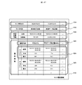
図7は、DBMS情報420のデータ構造を示す図である。
システム管理プログラム140は、計算機システム内で実行されるDBMS90に関する情報を、DBMS情報420としてシステム管理情報142中に保持する。この情報は、DBMS90の識別子であるDBMS ID 582を保持するエントリと、それが実行されるサーバ70の識別子であるサーバID 422を保持するエントリ、対応するDBMS90のデータ内部管理方法情報426を保持するエントリの組を含む。データ内部管理方法情報426は、DBMS90の型式により定まる、ログの出力フォーマットに関する情報を含む。
【0055】
以下、本実施の形態において、ログに対して割り当てる記憶装置40におけるデータキャッシュ42の量を定める処理について説明する。この処理は、システム管理プログラム140が行う。
【0056】
図8は、本処理開始時にシステム管理プログラム140に対して与えられる、処理設計情報850のデータ構造を示す図である。処理設計情報850は、処理を実施するDBMS90のDBMS ID 582を保持するエントリ、処理が実施されるDBの識別子であるDB ID 854を保持するエントリ、ログを用いて実行するRe-Run/Undo処理の処理性能に関する情報であるRe-Run性能856を保持するエントリ、Re-Run/Undo処理実施時の最大所要時間の設計情報であるRe-Run最大所要時間858を保持するエントリ、実行される処理の情報として、処理の識別子である処理ID 432を保持するエントリ、 その処理が実施される比率に関する情報である実行比率862を保持するエントリ、その処理において実施されるSQL文である実行SQL文860を保持するエントリ、処理内でそのSQL文が何回実行されるかの期待値を示す期待回数864を保持するエントリの組を含む。
【0057】
本実施の形態においては、Re-Run性能856は、Re-Run時に単位時間あたりに処理可能なログに記憶された処理の件数を示し、システムにおける実測値や、サーバ70の性能とDBMS90の論理的処理性能から求めた論理値、システム設計時の設定値等を与える。1つの処理で複数のSQL文が実施される可能性があり、処理ID 432に対応する実行SQL文860は複数存在しても良い。実行SQL文860が繰り返し実行される場合には、期待回数864にそれぞれ独立したものとしてカウントする。同じ処理に含まれるSQL文でも各種条件により実施されるSQL文が異なる可能性があり、実行SQL文860毎に異なる値を取り得る。なお、実行比率862や期待回数864は、設計値でもよいし、実測値でも良い。
【0058】
図9は、ログのキャッシュ量を定める処理の処理フローである。前述のように、処理開始時に処理設計情報850が与えられる。また、処理により利用されるDBやその記憶領域は既に定義されているものとして説明する。ただし、対応するDBMS90や仮想化機構から取得する情報を別途設計情報として管理者が与えることにより、それらが定義されていなくても本処理を実施できる。(ステップ1101)
処理設計情報850を参照し、Re-Run性能856とRe-Run最大所要時間858からRe-Run時に処理可能な処理の最大処理件数を求める。(ステップ1102)
処理設計情報850中の実行SQL文860を参照し、それらの中からINSERT/UPDATEを実施するSQL文と、その期待回数864を求める。(ステップ1103)
ステップ1103で求めたINSERT/UPDATEを行う実行SQL文860を1回実行した際に出力されるログの最大量を把握する。まず、対象となる実行SQL文860からデータの挿入/更新が行われる表とその属性の名前をそれぞれ把握する。そして、属性サイズ情報350を参照してそれらの最大サイズ354を求める。また、DBMS情報420中のデータ内部管理方法情報426からログの出力フォーマットの情報を取得し、それらから各実行SQL文860においてログとして出力される最大データ量を把握する。(ステップ1104)
ステップ1103とステップ1104で求めた値を用いて、ログを出力する各処理の1件あたりのログ出力量を計算する。この値は、ある処理に属するINSERT/UPDATEを行う実行SQL文860によるログの最大データ量と期待回数864の積の値の和として求める。更に、DBMS情報420中のデータ内部管理方法情報426からログのヘッダや処理がコミットされたときに出力されるデータ等の出力フォーマットに関する情報を把握し、その分もログ出力量に加える。最後に、求めた値を、記憶装置のブロックサイズ(512byte)を単位として切り上げ処理を実施する。(ステップ1105)
ステップ1105で求めたログを出力する処理1件あたりのログ出力量と、処理設計情報850中の各処理における実行比率862から、ログを出力する処理1件あたりの平均ログ出力量を求める。そして、この値とステップ1102で求めたRe-Run時に処理可能な最大処理件数の積の値に、事前に定めた余裕分を加えた量をRe-Run時に必要となるログ量とする。(ステップ1106)
ステップ1106で求めた量のログが記憶装置40上に常に存在するようなキャッシュ量の設定を求める。DBMS90のログがどの記憶装置40に記憶され、更に、そのログがどのLU208上に記憶され、そのLU208がどのキャッシュグループに存在するか、マッピング集約情報から把握する。求めたキャッシュグループに対し、ステップ1105で求めたRe-Run時に必要となるログ量以上のキャッシュを割り当てる。なお、記憶装置40が書き込まれたデータを2重化する場合には、必要に応じてログ量に対して2倍のキャッシュ量が必要であるとする。
【0059】
ログが記憶されるLU208がフリーキャッシュグループに属する場合には、それらのみのキャッシュグループを定義し、そこにRe-Run時に必要となるログ量を割り当てることとする。複数のLU208に分割されてログが記憶され、かつ、それらが異なるキャッシュグループに属する場合には、それぞれにRe-Run時に必要となるログ量を割り当てる。ログが記憶されるLU208が属するキャッシュグループに他のデータも記憶されるマッピングがマッピング集約情報から得られた場合、例えば、以前のキャッシュグループの設定値から他のデータが記憶される分のキャッシュ量を別途求め、その値にRe-Run時に必要となるログ量を加算した値をそのキャッシュグループのキャッシュ量とする。(ステップ1107)
ステップ1106で求めたキャッシュグループとそのキャッシュ量の設定を、記憶装置40に対して発行する。処理に利用されるDBがDBMS90でまだ定義されていない場合には、その定義と記憶領域を確保した後にこのステップを実施する。(ステップ1108)
そして、処理を完了する。(ステップ1109)
これまで、記憶装置40はLU208を外部装置に提供し、それはI/Oパス34を経由してアクセスされるとしてきた。記憶装置40がファイル202を外部装置に提供し、そのファイル202がネットワークファイルシステムプロトコルを用いてネットワーク24経由でアクセスされてもよい。
【0060】
図10は、上述した第一の実施形態の変形例であり、記憶装置40がファイル202を外部装置に提供する場合の計算機システムの構成を示す図である。その場合には、以下のような違いがある。
【0061】
サーバ70はI/OパスI/F 32を有さなくともよい。OS72は外部装置が提供するファイル202を、ネットワークファイルシステムプロトコルを用いてネットワークI/F 22、ネットワーク24経由でアクセスするネットワークファイルシステム82を含み、ボリュームマネージャ78やファイルシステム80を有さなくともよい。ネットワークファイルシステムは領域マッピング情報300をOS管理情報74中に有する。DBMS90により認識されるファイル202と記憶装置40から提供されるファイル202があるルールに従って対応する場合、その対応関係を定めるルールの情報のみがOS管理情報74中に保持されても良い。この場合には、システム管理プログラム140は対応関係を定める情報を取得し、それから領域マッピング情報300を作成し、マッピング集約情報中に記憶する。
【0062】
記憶装置40はI/OパスI/F 32を持たなくてもよく、ファイルを外部装置に対して提供する。記憶装置40の制御プログラム44はファイルシステム80が提供する機能を有し、記憶装置40内に存在するLU208の記憶領域を仮想化し、ファイル202を提供する。また、制御プログラム44は1つ以上のネットワークファイルシステムプロトコルを解釈し、ネットワーク24、ネットワークI/F 22経由で外部装置からそのプロトコルを用いて要求されるファイルアクセス処理を実施する。この記憶装置40では、キャッシュグループのメンバの管理単位がLU208ではなくファイル202を単位とする。
【0063】
データのマッピングに関しては、図2で説明したデータのマッピング階層構成において、ファイル202以下が全て記憶装置40により提供されるようになり、サーバ70はOS72内のネットワークファイルシステム82を用いて記憶装置40上にあるファイル202をアクセスする。
記憶装置40がファイル202を外部装置に提供する場合、本実施の形態において実施する処理においては、LU208を考えている部分を記憶装置40上のファイル202に対応させる。
【0064】
・第二の実施の形態
第二の実施の形態では、DBMSで実施される処理の設計情報から表・索引データに対するキャッシュ量の初期割り当てを好適化する。DBMSで実施される処理の組があらかじめ明確になっている場合、処理内容の解析からあるデータ全体へのアクセス量はおおよその見当がつく。データ内でのおおよそのアクセス特性を与え、それと処理内容の解析結果を基に、ある量のキャッシュを割り当てた場合のキャッシュヒット率の概算値を求め、データに対して割り当てるキャッシュ量を決定する。本実施の形態では、計算機システムが、DBMSのキャッシュと記憶装置のデータキャッシュを1つのキャッシュ領域とみなして管理するための機構を有し、双方で記憶データの重複がほとんどないことを前提とする。
【0065】
図11は、第二の実施形態による計算機システムの構成を示す図である。第二の形態における計算機システムの構成は、第一の形態のものと基本的に同じである。以下、第一の形態との差異を中心にして第二の実施形態について説明する。
【0066】
DBMS90は、メモリ14上の領域をキャッシュ94として利用し、DBMS管理情報92中に表データ量情報700とB-Tree索引情報710を含むDBMS90bとなる。DBMS90bは属性サイズ情報350を保持する必要はない。DBMS90bは、データ構造毎にキャッシュ94の利用量を管理する機能を有し、その設定情報は表データ量情報700やB-Tree索引情報710に含まれる。DBMS90bは、データ構造毎のキャッシュ94の利用量を動的に変更するためのソフトウェアインターフェイスを有する。
【0067】
管理エージェント144がシステム管理プログラム140からの指示に従って実行する処理に、データ構造毎のキャッシュ94の利用量の変更をDBMS90bに指示することが加わる。システム管理プログラム140は、システム管理情報142中に保持するDBMS情報420にデータ内部管理方法情報426を有する必要はない。
【0068】
更に大きな違いとして、I/Oパス34を通してキャッシュ化要求954とキャッシュ化要求付ライト要求958が伝達される。キャッシュ化要求954は、記憶装置40b内に格納されているデータをデータキャッシュ42に保持することを求める要求であり、通常のリード要求950と同様の形式でデータが指定される。キャッシュ化要求付ライト要求958は書き込まれたデータを記憶装置40b内でデータキャッシュ42に保持することを求める要求である。
【0069】
キャッシュ化要求954とキャッシュ化要求付ライト要求958を使用した例として、I/Oパス34上でのデータ転送プロトコルとしてSCSI(Small Computer System Interface)を基にしたものを利用する場合について説明する。第一の方法としては、キャッシュ化要求954とキャッシュ化要求付ライト要求958に対応するオペレーションコードを新規に作成する。第二の方法としては、既存のプリフェッチとライトのオペレーションコードを利用し、コマンド中のコントロールバイトのベンダ依存ビットにキャッシュヒントを意味するビットを定義し、その値が“0”の時には通常の処理を、その値が“1”のときに、オペレーションコードがプリフェッチコマンドの場合にはキャッシュ化要求954、オペレーションコードがライトのときにはキャッシュ化要求付ライト要求958として処理する。なお、他のデータ転送プロトコルを用いても同様の方法で実現可能である。
【0070】
本実施の形態においては、仮想化スイッチ60は、仮想ボリューム206へのキャッシュ化要求954とキャッシュ化要求付ライト要求958を、対応する管理構造へのキャッシュ化要求954やキャッシュ化要求付ライト要求958に変換する機能を制御プログラム64により実現する仮想スイッチ60bとなる。サーバ70上のOS72は、上位プログラムからのキャッシュ化要求954とキャッシュ化要求付ライト要求958をI/Oパス34を通して送出可能なOS72bに変更される。DBMS90bはキャッシュ化要求954とキャッシュ化要求付ライト要求958を送出する機能を有する。記憶装置40は、制御プログラム44によりキャッシュ化要求954とキャッシュ化要求付ライト要求958が解釈可能な記憶装置40bとなる。
【0071】
本実施の形態において、記憶装置40のキャッシュグループ情報460は記憶装置40bではキャッシュグループ情報460bとなる。キャッシュグループ情報460b中のヒント機能468の値が“ON”であるキャッシュグループに属するLU208内のデータに対してキャッシュ化要求954やキャッシュ化要求付ライト要求958を受け取った場合、それらにより指示されたデータに関しては長時間データキャッシュ42に保持するようにする。例えば、記憶装置40bがキャッシュグループ内のデータ領域の管理を、LRU置換アルゴリズムを用いて行う場合、要求データをMRUデータ化する。なお、キャッシュ化要求954を受け取り、それで指示されたデータがデータキャッシュ42内に存在しない場合、そのデータをHDD16から読み出してデータキャッシュ42上に格納する。そのLU208に対してリード要求950やライト要求956があった場合、その要求を完了後、そのデータは原則データキャッシュ42には保持しない。記憶装置40bの内部制御の都合上、データキャッシュ42に保持する必要がある場合でも、保持する必要がなくなったら、そのデータを保持する領域がすぐに再利用されるようにする。(前述の例ではその時点のLRUデータとして扱う。)
図12は、キャッシュ化要求954とキャッシュ化要求付ライト要求958を用いた際の、DBMS90bと記憶装置40bとの間のデータ制御を説明した図である。各領域での処理開始時にDBMS90bや記憶装置40bはそのデータをキャッシュ94やデータキャッシュ42上に保持していない。なお、図を簡略化するため、処理の受諾や完了の応答は図から省いてある。
【0072】
領域962は、DBMS90bがデータの読み出しのみを行った際のデータ制御を示す。まず、DBMS90bがリード要求950を記憶装置40bに発行し、それに応答して記憶装置40bがDBMS90bに要求されたデータを転送する(データ転送952)。記憶装置40bはデータを転送した後、そのデータをデータキャッシュ42に保持しない。DBMS90bは転送されたデータをキャッシュ94に格納する。DBMS90bは、データをキャッシュ94から破棄する際に、リード要求950と同様の方法でキャッシュ化要求954を記憶装置40bに送出する。キャッシュ化要求954を受け取った記憶装置40bは要求データをHDD16から読み出し、データキャッシュ42上に保持する。
【0073】
領域964は、DBMS90bがデータの更新を行う際の第一のデータ制御を示す。DBMS90bがデータをキャッシュ94上に読み出すまでは領域962と同様である。その後、DBMS90bはキャッシュ94上のデータを更新し、更新したデータを記憶装置40bに書き込む(ライト要求956+データ転送952)。記憶装置40bは、受領したデータを対応するHDD16に書き込み、データキャッシュ42上にそのデータを保持しない。その後、DBMS90bは、データをキャッシュ94から破棄する際に、キャッシュ化要求954を記憶装置40bに送出する。キャッシュ化要求954を受け取った記憶装置40bは要求データをHDD16から読み出し、データキャッシュ42上に保持する。
【0074】
領域966は、DBMS90bがデータの更新を行う際の第二のデータ制御を示す。DBMS90bがデータをキャッシュ94上で更新するまでは領域964と同様である。データ更新後、本制御では、キャッシュ94上からデータを破棄するまで記憶装置40bへのデータ書き込みを行わない。データをキャッシュ94から破棄する際に、DBMS90bは、更新したデータを記憶装置40bに書き込むと同時にキャッシュ化要求を行う(キャッシュ化要求付ライト要求958+データ転送952)。キャッシュ化要求付ライト要求958を受け取った記憶装置40bは書き込まれたデータをデータキャッシュ42上に保持する。データのHDD16への書き込みは適宜行う。
【0075】
なお、これまでの説明はキャッシュ化要求954を用いた方法で説明してきたが、DBMS90bがデータ破棄時に常にキャッシュ化要求付ライト要求958を発行しても良い。この場合、各装置はキャッシュ化要求954を処理できる必要はない。
【0076】
図13は、キャッシュグループ情報460bのデータ構造を示す図である。第一の実施の形態と比較して、キャッシュグループID 462を保持するエントリ毎にヒント機能468を保持するエントリが付加される。ヒント機能468はキャッシュヒント機能が有効か無効かを示す情報で、有効な場合は“ON”が、無効な場合には“OFF”がその値として記憶される。ヒント機能468の値が“ON”のときの制御は前述の通りである。その値が“OFF”の場合は、一般的なキャッシュのデータ管理手法を用いる。例えば、データキャッシュ42内に保持されるデータをLRU置換アルゴリズムで管理し、アクセスされたデータはその種別に関わらず全てその時点でMRUデータ化する。
【0077】
図14は、表データ量情報700のデータ構造を示す図である。表データ量情報700は、表のデータ構造名346を保持するエントリと、その表におけるデータページの大きさに関する情報であるデータページサイズ702を保持するエントリとその表が利用しているデータページ数704を保持するエントリ、そのデータが利用可能なキャッシュ94の量に関する情報であるキャッシュ量466を保持するエントリを有する。
【0078】
図15は、B-Tree索引情報710のデータ構造を示す図である。B-Tree索引情報710は、索引のデータ構造名346を保持するエントリと、その索引が付加された表のデータ構造名346である対応表名712を保持するエントリ、データページサイズ702を保持するエントリ、データページ数704を保持するエントリ、データページのうち、B-Tree索引のリーフノードのデータを保持しているデータページ数であるLeafノードページ数714を保持するエントリ、その索引のキャッシュ量466を保持するエントリ、その索引を利用して検索が行われる属性の属性名352の組である検索属性716を保持するエントリ、検索属性716における1回の検索で得られると期待されるタプル数の情報である期待タプル数718を保持するエントリの組からなる。なお、1つの索引に複数の検索属性716とそれに対応する期待タプル数718が存在することがある。また、期待タプル数718は、対応する表のデータ解析により得られる値で、平均値や最頻値、あるいは各種指標から計算した値が用いられる。
【0079】
以下、本実施の形態において、DBMS90bや記憶装置40bにおけるキャッシュ量を設定する処理を説明する。本処理は、システム管理プログラム140が行う。
【0080】
図16は、キャッシュ量情報720のデータ構造を示す図である。キャッシュ量情報720は、処理開始時にシステム管理プログラム140に対して与えられる、DBMS90bや記憶装置40bにおいて利用可能なキャッシュ量に関する情報であり、処理が実施されるDBMS90bのDBMS ID 582を保持するエントリとそのDBMS90bで利用可能なキャッシュ94の量に関する情報であるキャッシュ量722を保持するエントリの組と、処理に利用されるデータを保持する記憶装置40b(装置)の識別子である装置ID 572を保持するエントリとそこで利用可能なデータキャッシュ42の量であるキャッシュ量722を保持するエントリの組を含む。
【0081】
図17は、処理開始時にシステム管理プログラム140に対して与えられる情報である、表アクセス分布情報730のデータ構造を示す図である。表アクセス分布情報730には、処理に利用される表のデータ構造名346を保持するエントリと、その表におけるデータページへのアクセス頻度の分布に関する情報であるアクセス分布732を保持するエントリの組を含む。アクセス分布732は、アクセス頻度が高い順に並び替えられているとし、理論値/実測値のどちらでもよい。その分布がわからない場合には一般化されたZipf分布に従うとし、k番目に高いアクセス確率を持つデータページへのアクセス確率をF(k)としたときに、F(k) = C/kα (α:パラメータ(0<=α)、C:補正係数(C=1/Σ(1/ cα)))である仮定する。このとき、データページ数が少ない場合にはαを0に近い値(例えば0.25程度)とし、データページ数が多い場合にはαを1に近い値(例えば0.75程度)とする。また、データのINSERTが行われる、INSERTされたデータがある程度の時間経過後に更新される、等の時間的局所性を有する処理が行われる場合には、それによりアクセスされる領域が限られ、データページの一定割合(例えば8割)はデータアクセスがされない(アクセス確率が0)としてもよい。
【0082】
図18は、システム管理プログラム140がシステム管理情報142中に保持する期待アクセスページ数情報780のデータ構造を示す図である。期待アクセスページ数情報780は、処理ID 432を保持するエントリ、その処理によりアクセスされるデータ構造のデータ構造名346を保持するエントリと、そのデータ構造に対して処理あたり幾つの異なるデータページが利用されると期待されるかの情報を示す期待アクセスデータページ数784を保持するエントリの組からなる。期待アクセスデータページ数784は、参照と更新(データの挿入を含む)の双方を含めてアクセスされるデータページ数の総計値を保持するエントリと、更新が行われる(参照のみを除いた)データページ数が保持されるエントリを有する。
【0083】
期待アクセスページ数情報780は設計情報として管理者が与えてもよいし、また、キャッシュ量を設定する処理を開始する前に、システム管理プログラム140に処理設計情報850を与え、それから以下のように作成してもよい。なお、この場合の処理設計情報850には、Re-Run性能856とRe-Run最大所要時間858を保持するエントリが含まれなくともよい。
【0084】
まず、処理設計情報850から実行SQL文860を参照し、それぞれのSQL実行計画をDBMS90bから取得、各処理ステップでアクセスされるデータ構造とそのアクセス方法(データの挿入/更新を含む)を把握する。その結果と、DBMS90bから取得するB-Tree索引情報710を利用し、SQL実行計画中の各処理ステップにおいて処理するデータ量(タプル数)を把握する。求めたアクセスされるデータ構造と、そのアクセス方法と、各処理ステップにおける処理データ量から、アクセスされるデータページ数とアクセス内容(参照/更新)を把握する。このとき、基本的に、各タプルは異なるデータページに存在すると考える。ただし、あるB-Tree索引により検索されるタプルがどのようにデータページに分散されるかの情報をB-Tree索引情報710中に含めておき、それを利用してアクセスされるデータページ数をより詳細に求めてもよい。この処理の全部/一部として、DBMS90bでSQL実行計画を作成するときに内部的に見積られた値をSQL実行計画と同時に出力させ、その値を利用してもよい。求めた値に、実行SQL文860に対応する期待回数864を乗じた値を期待アクセスページ数情報780に設定する。
【0085】
図19は、DBMS90bや記憶装置40bにおけるキャッシュ量を設定する処理の処理フローである。本処理においては、各データ構造毎に、DBMS90bと各記憶装置40bにおけるキャッシュ量の割り当てを求めるものとする。処理開始前に期待アクセスページ数情報780がシステム管理情報142中に保持される。処理開始時、処理設計情報850b、キャッシュ量情報720、表アクセス分布情報730が与えられる。なお、処理設計情報850bは、処理設計850から実行SQL文860と期待回数864を保持するエントリが除かれたものである。ここでは、処理により利用されるDBやその記憶領域は既に定義されているものとして説明する。ただし、対応するDBMS90bや仮想化機構から取得する情報を別途設計情報として管理者が与えることにより、それらが定義されていなくても本処理を実施できる。(ステップ1401)
まず、表・索引の各データ構造に対して、処理を実施する際に必要となる最小限の量として、DBMS90bにおけるキャッシュ94と各記憶装置40bにおけるデータキャッシュ42での利用量を、それぞれ事前に定められる一定量分割り当てる。
【0086】
なお、本処理の全てのステップにおいて、データの記憶先の記憶装置40bは、システム管理情報142中に保持されているマッピング集約情報から把握する。複数の記憶装置40bに対してデータが記憶されている場合には、特に断らない限り、マッピング集約情報から各記憶装置40b毎のデータの記憶比率を把握し、それに比例したキャッシュ量をそれぞれに割り当てる。DBMS90bや記憶装置40bにおいて、キャッシュ量情報720中にキャッシュ量722として与えられたキャッシュの利用量の上限を超えた量を要求する場合にはエラーとして処理を終了する。(ステップ1402)
次に、DBMS90bからB-Tree索引情報710を取得する。その後、各索引毎に、取得した情報中のデータページ数704とLeafノードページ数714の差とデータページサイズ702から、リーフノード以外のデータを記憶するデータページの量を把握し、それと同量のキャッシュ94の利用量を割り当てる。(ステップ1403)
続いて、各索引毎に、Leafノードページ数714とデータページサイズ702からリーフノードのデータ量を把握し、それと同量のデータキャッシュ42の利用量と、それに対して事前に定められた比率(例えば20%)分のキャッシュ94の利用量を割り当てる。(ステップ1404)
各表毎にキャッシュ効果関数を指定し、ステップ1601から始まる処理を実施し、各表のデータに対してキャッシュ94の利用量を指定する。ここで、キャッシュ効果関数E(i)は「あるデータ構造における、データを利用するときに既にそのデータがキャッシュ上に存在する(キャッシュヒットする)確率の、キャッシュ上に保持可能なデータページ数をi-1からiに増加させたときの増分」と定義する。従って、ΣE(i)=1である。ここでは、近似として表アクセス分布情報730で与えられるアクセス分布732をそのまま与える。ただし、アクセス分布732をベースにキャッシュ効果関数を別途定義してもよい。(ステップ1405)
記憶装置40bにおいて、データキャッシュ42がライトキャッシュとしても利用される場合に、各データ構造にその利用分を考慮したデータキャッシュ42を割り当てる。まず、処理設計情報850b中の期待アクセスページ数情報720を参照し、期待アクセスデータページ数784の更新データページ数の値が0でないデータ構造を有する処理を求める。それらの処理のうちどれか1つが実施された際の各データ構造毎の期待データページ更新数を、処理設計情報850b中の処理の実行比率862による重み付けを考慮しながら期待アクセスデータページ数784の更新データページ数から求める。次に、処理設計情報850b中のRe-Run性能856とRe-Run最大所要時間858からRe-Run時に処理可能な処理の最大処理件数を求め、それと既に求めた更新が行われる処理あたりの各データ構造毎の期待データページ更新数の積を求める。
【0087】
求めた値と、データ構造における現在のキャッシュ94の割り当て量に事前に定めた割合(例えば70%)を乗じた値を比較し、そのうち値が小さな方をデータ構造に対するライトキャッシュ必要量とする。データキャッシュ42の割当量がその値未満のデータ構造に対して、その量に達するようにデータキャッシュ42の割り当てを行う。なお、ある記憶装置40bが書き込まれたデータを2重化する場合には、必要に応じて求めた値の2倍のキャッシュ量が必要であるとする。
【0088】
なお、本ステップは必ずしも実施される必要はない。この場合、処理設計情報850b中にRe-Run性能856やRe-Run最大所要時間858が保持される必要はない。(ステップ1406)
各表毎にキャッシュ効果関数を指定し、ステップ1601から始まる処理を実施し、各表のデータに対してデータキャッシュ42を割り当てる。ここでも、キャッシュ効果関数は、近似として表アクセス分布情報730で与えられるアクセス分布732をそのまま与える。ただし、アクセス分布732をベースにキャッシュ効果関数を別途に定義してもよい。特に、DBMS90bでのキャッシュ94の制御方法、記憶装置40bにおけるデータキャッシュ42の制御方法の違いを考慮して、ステップ1405と異なる関数を用いてもよい。(ステップ1407)
これまでに求めたキャッシュ量の設定を、DBMS90bや記憶装置40bに対して発行する。処理に利用されるDBがDBMS90bでまだ定義されていない場合には、その定義と記憶領域の確保と同時、もしくは確保後にこのステップを実施する。
【0089】
記憶装置40bへのキャッシュ量の指示は以下のように行う。マッピング集約情報を参照し、処理で利用されるデータ構造のデータを保持するLU208を確認し、それがフリーキャッシュグループに属している場合には、同じデータ構造のデータが記憶されるLU208をメンバとするキャッシュグループを作成するように記憶装置90bに対して指示を出す。その後に各データ構造を記憶するLU208が属するキャッシュグループに対して求めたキャッシュ量の設定を行う。なお、あるデータ構造のデータが異なるキャッシュグループに属する複数のLU208上に記憶される場合には、マッピング集約情報からそれぞれに記憶されているデータ量を把握し、それに比例するように割当を行う。マッピング集約情報から、データ構造のデータが他のデータと同一のキャッシュグループに属することになる場合には、それらのデータ構造に対して割りあてられた量の和としてキャッシュグループのキャッシュ量を設定する。このとき、本処理によるキャッシュ量の割当とは別に割り当てが行われている場合には、必要に応じて、以前のキャッシュグループの設定値から他のデータが記憶される分のキャッシュ量を別途求める。(ステップ1408)
そして、処理を完了する。(ステップ1409)
なお、本処理は、記憶装置40bのデータキャッシュ42の割当のみを実施する場合に実行しても良い。この場合、DBMS90bにおける各データ構造へのキャッシュ94の割当が処理開始時に与えられる。そして、ステップ1402からステップ1405までと、ステップ1408におけキャッシュ94に関する処理は実施しない。
【0090】
図20は、キャッシュ効果関数を利用してキャッシュ量の割り当てを行う処理の処理フローを示す。本処理はステップ1401から始まる処理の一部であり、その処理が利用可能な情報は全て利用できる。以下、説明のため、処理に利用される表に通番tを付加し、各表毎に定まる定数や関数等は、この通番を利用してそれぞれのものとして識別する。本処理の開始時、各表毎にキャッシュ効果関数Et(i)と割り当てを行うキャッシュがDBMS90bのキャッシュ94か記憶装置40bのデータキャッシュ42かに関する指定が与えられる。また、必要に応じて、現在のキャッシュ割当量を求める方法も指定される。(ステップ1601)
現在までに割り当てられたキャッシュ量を各表毎に求め、それをデータページ数に換算した値をntに設定する。このとき、処理開始時に特に指定がない限り、キャッシュ94とデータキャッシュ42のそれぞれに割り当てられた値の総計としてキャッシュ量を求める。(ステップ1602)
次に、各表毎に以下の値を計算する。
【0091】
At = Σ((表に対する処理の期待アクセスページ数(総計値))×(処理の実行比率))
ここで、Σは処理に関して総和を取ることを示す。表に対する処理の期待アクセスページ数は期待アクセスページ数情報780から求めることができ、処理の実行比率は処理設計情報850bから求めることができる。(ステップ1603)
次に、各表毎に指定されたキャッシュ効果関数を用いて以下の値を計算する。
【0092】
Wt(nt) = At×Et(nt)
(ステップ1604)
ステップ1604で求めたWt(nt)の値が一番大きな表を選択し、その表に対して1データページ分キャッシュを割り当てる。
【0093】
データキャッシュ42の割り当ての場合には、Wt(nt)の選択後に以下の処理も行う。マッピング集約情報を参照して、その表のデータがどの記憶装置40bにどれだけの量が記憶されているかを求め、その量に比例して追加されたデータキャッシュ42の割り当て量を記憶装置40b間で分配する。このとき、特定の記憶装置40bにおける、各データ構造に対するデータキャッシュ42の割当量の和がキャッシュ量情報720中にキャッシュ量722として与えられた値に達している場合には、そこへの割り当ては不可能とし、他の記憶装置40bのみを考えて追加されたキャッシュ量の分配を行う。選択された表において、そのデータを保持する全ての記憶装置40bでデータキャッシュ42の割り当てが不可能と判断される場合、その表に対するキャッシュの割り当ては行わず、次にWt(nt)の値が大きな表をキャッシュの割り当て対象とし、同様の確認を繰り返す。
【0094】
そして、選択された表のntの値に1を加える。(ステップ1605)
キャッシュが全て割り当てられたか確認し、まだ割り当て可能な未割り当て分が存在する場合にはステップ1604に戻る。割り当てが完了した(これ以上割り当てを続行できない)場合には、ステップ1607に進み、処理を完了する。(ステップ1606)
ここで、処理を完了する。(ステップ1607)
これまで、記憶装置40bはLU208を外部装置に提供し、それはI/Oパス34を経由してアクセスされるとしてきた。第一の実施の形態と同様に、記憶装置40bがファイル202を外部装置に提供し、そのファイル202がネットワークファイルシステムプロトコルを用いてネットワーク24経由でアクセスされてもよい。この場合、第一の実施の形態と同様の対応関係がとられる。
【0095】
主な相違点として、記憶装置40bでは、キャッシュグループのメンバの管理単位が、ファイル202が単位となり、本実施の形態において実施する処理においては、LU208の部分が記憶装置40b上のファイル202に対応するようになる。
・第三の実施の形態
第三の実施の形態は、第二の実施の形態において利用されていたキャッシュ化要求954とキャッシュ化要求付ライト要求958が利用されない条件の下、DBMSで実施される処理の設計情報から表・索引データに対するキャッシュ量の初期割り当てを好適化する。つまり、本実施の形態では、DBMSのキャッシュと記憶装置のデータキャッシュがそれぞれ独立に管理され、双方の間でキャッシュ上に保持されるデータが一部重複することを前提とする点が第二の実施の形態と異なる。
【0096】
第三の実施における計算機システムの構成は、基本的に第二の実施形態のものと似ている。以下、本実施の形態について第二の実施形態との違いを中心にして説明する。
【0097】
前述のように、本実施の形態においては、キャッシュ化要求954とキャッシュ化要求付ライト要求958が利用されない。そのため、記憶装置40b、仮想化スイッチ60b、OS72bは、第一の実施の形態と同じ記憶装置40、仮想化スイッチ60、OS72となる。また、DBMS90bは、キャッシュ化要求954とキャッシュ化要求付ライト要求958を送出する機能を有さないDBMS90cになる。
【0098】
記憶装置40では、データキャッシュ42内のデータ管理に関し、一般的な手法を用いる。例えば、データキャッシュ42内に保持されるデータをLRU置換アルゴリズムで管理し、アクセスされたデータはその種別に関わらず全てその時点でMRUデータ化する。
【0099】
本実施の形態では、ステップ1401から始まるキャッシュ量を設定する処理がステップ1401bから始まる処理に変更される。図21は、ステップ1401bから始まるDBMS90cや記憶装置40におけるキャッシュ量を設定する処理の処理フローである。ステップ1401bから始まる処理では、ステップ1401から始まる場合に実行されるステップ1407がステップ1421からステップ1423までの処理に変更される。なお、本処理は、第二の実施の形態と同様にして、記憶装置40のデータキャッシュ42の割当のみを実施する場合に実行しても良い。
【0100】
表のデータ量を表データ量情報700から求め、その値の一定割合(例えば90%)以上の量のキャッシュ94が割り当てられた表を、以降の記憶装置40のデータキャッシュ42の割り当て対象から除く選択処理を行う。(ステップ1421)
次に、ステップ1407と同様に、各表毎にキャッシュ効果関数を指定し、ステップ1601から始まる処理を実施し、各表のデータに対してデータキャッシュ42の利用量を割り当てる。このとき、ステップ1602で設定する現在までに割り当てられたキャッシュ量は、記憶装置90におけるデータキャッシュ42の割当量のみを考慮するように指示する。キャッシュ効果関数は、キャッシュ94とデータキャッシュ42の間でのデータの重複を考慮しないものを与えるとし、近似として表アクセス分布情報730で与えられるアクセス分布732をそのまま与える。また、別途キャッシュ効果関数を定義してもよい。なお、本ステップで割り当てたデータキャッシュ42の量は、全体の割当量とは別に記憶する。(ステップ1422)
ステップ1422で割り当てたデータキャッシュ42に関し、キャッシュ94とデータキャッシュ42の間でのデータ重複によるデータキャッシュ42のキャッシュ効果低減分を考慮する、データキャッシュ42の割り当ての再調整を行う。本実施の形態では、現在のキャッシュ94の利用量に一定割合(例えば80%)を乗じた値(以下、Ntと表記)未満の領域では、データキャッシュ42を利用してもその効果がないと判断する。まず、ステップ1422でデータキャッシュ42が割り当てられなかった表を再調整の対象から外す。
【0101】
次に、ステップ1422でデータキャッシュ42が割り当てらてたものに対してキャッシュ効果があるか確認する。調整対象の各表において、ntを現時点でのデータキャッシュ42の割当量から求めたデータページ数としたとき、確認指標としてnt-Nt<0を用い、それ満たす表が存在する場合には、その値が最も小さな表のステップ1422以降で割り当てたデータキャッシュ42を全て開放し、調整対象から外す。そして、ステップ1422で行ったデータキャッシュ42の割当処理を再度実行する。以下、確認指標を満たす表が存在する間この確認と再割当処理を繰り返す。この確認で、全ての表でステップ1422で割り当てたデータキャッシュ42を開放することになった場合は、エラー発生として処理を終了する。なお、確認指標にキャッシュ効果より強く反映させるために、nt-Nt<0の代わりに(nt-Nt)/Wt(Nt)<0(Wt(i)はステップ1604での定義を利用)を用いてもよいし、その他の確認指標を用いてもよい。
【0102】
更に、キャッシュ効果を高めるため、調整対象の全ての表でnt-Nt>0を満たす場合に、キャッシュ効果を考慮した割当の調整を行う。調整対象の各表においてVt=ΣWt(i)(ただしΣはNt<=i<=ntの和を取ることを意味する)を計算し、その値が最も小さな表を選択する。その表に対してステップ1422以降で割り当てられたデータキャッシュ42を開放した場合に、他の調整対象の表に割り当てる方法をステップ1422と同様にして求める。ここで、新規割当先に対応するWt(i)の値の和を計算し、その値がデータキャッシュ42を開放した表におけるVtよりも大きな値の場合、求めたキャッシュ割当の再調整を実施するとする。以下、この確認を再調整を実施しないと判断されるまで繰り返す。(ステップ1423)
これまで、記憶装置40はLU208を外部装置に提供し、それはI/Oパス34を経由してアクセスされるとしてきた。第一の実施の形態と同様に、記憶装置40がファイル202を外部装置に提供し、そのファイル202がネットワークファイルシステムプロトコルを用いてネットワーク24経由でアクセスされてもよい。この場合、第一の実施の形態と同様の対応関係がとられる。
【0103】
主な相違点として、記憶装置40では、キャッシュグループのメンバの管理単位がファイル202単位となり、本実施の形態において実施する処理においては、LU208の部分が記憶装置40上のファイル202に対応するようになる。
・第四の実施の形態
第四の実施の形態では、DBMSで実施される処理の設計情報と稼動統計情報と組み合わせ、記憶装置におけるデータキャッシュ量のチューニングによりキャッシュ効果を向上させる。事前解析により得た処理のデータページ数の期待値と処理実行時の稼動統計情報を組み合わせることにより、問題と判断された処理や処理全体におけるキャッシュ量変更時の処理時間の変化を見積り、それを基に好適なキャッシュの割り当て方法を発見する。
【0104】
図22は、第四の実施形態による計算機システムの構成を示す図である。第四の実施における計算機システムの構成は、基本的に第一の実施の形態とものと似ている。以下、本実施の形態について、第一の実施形態との相違点を中心にして説明する。
【0105】
本実施の形態においては、記憶装置40がデータキャッシュ42における稼動統計情報を取得する記憶装置40dとなる。記憶装置40dにおいて、キャッシュグループにおけるキャッシュデータ置換制御は、それぞれ独立にLRU置換アルゴリズムを用いてわれる。前記アルゴリズムによるデータ置換によりデータキャッシュ42に存在しなくなったデータの記憶領域に関しても、データ置換後も一定量分は仮想管理領域としてLRU置換アルゴリズムの管理リスト中にその情報を記憶し、稼動状況の計測に利用する。制御プログラム44は、データキャッシュ42の稼動状況を計測し、管理情報46中にキャッシュモニタ情報362として保持する。このとき、LRU置換アルゴリズムのキャッシュセグメント(データキャッシュ42の領域管理単位)管理リストを等サイズの複数領域に分割し、分割領域毎にヒット数を計測する。更に、仮想管理領域に関しても実管理領域(実際にデータに対してキャッシュセグメントが割り当てられている領域)と等サイズの領域に分割して実管理領域と同様にヒット数を計測する。また、記憶装置40dは、外部からの要求に応じて、キャッシュモニタ情報362をネットワーク24を介して外部に送信する機能を有する。
【0106】
DBMS90は、メモリ14上の領域をキャッシュ94として利用するDBMS90dとなる。また、DBMS90dは、内部で利用されるソフトウェア機能や各データ構造のデータページ等の内部リソースに関して、それを利用する際に待ちが何回発生したかに関する稼動統計情報を収集し、それをDBMS管理情報92中にDBMSモニタ情報410として保持する。特に、本実施の形態においては、各データ構造毎にそのデータページを利用しようとした際に何回待ちが発生したかの累積値を保持する。
【0107】
サーバ70上では、DBMS90dの他にAPプログラム100が実行される。APプログラム100は、ユーザが行う業務のためにサーバ70上で実行されるプログラムであり、DBMS90dに対して処理要求を発行するものとする。APプログラム100は、HDD16もしくは記憶装置40からメモリ14に読み出されてCPU12により実行される。メモリ14上に読み込まれたAPプログラム100は、その管理情報であるAPプログラム管理情報102を有する。
【0108】
本実施の形態におけるAPプログラム100は、1つ以上の処理の組として実現され、それぞれに処理ID 432が付加されている。ユーザはそのいずれかの処理実行を要求し、APプログラム100はそれに応じて処理を実施する。APプログラム100は受け付けた処理要求のキューイング制御を実施し、APプログラム100からDBMS90dに対して処理要求を発行した場合には、DBMS90dで即座に処理を開始できるものとする。APプログラム100は処理に関する実行統計情報を取得し、それをオンラインJobモニタ情報430としてAPプログラム管理情報102中に保持する。APプログラム100は、APプログラム管理情報102を外部プログラムが読むためのソフトウェアインターフェイスを有する。
【0109】
DBMS90dとAPプログラム100が1台のサーバ70上で複数同時に実行されてもよい。また、DBMS90dとAPプログラム100が異なるサーバ70上で実行されてもよく、その場合には、APプログラム100はネットワーク24を経由してDBMS90dに処理要求を伝達する。
管理エージェント144がシステム管理プログラム140からの指示に従って実行する処理に、APプログラム管理情報102中に記憶されている情報の読み出しが加わる。
システム管理プログラム140は、システム管理情報142中に保持するDBMS情報420にデータ内部管理方法情報426を有する必要はない。その代わり、システム管理情報142中にHDD性能情報612を保持する。
【0110】
図23は、キャッシュモニタ情報362のデータ構造を示す図である。
キャッシュモニタ情報362は、LU 208が外部装置からアクセスされた場合にどのキャッシュ領域にヒットしたかに関する稼動統計情報であり、実管理領域の分割数を示す実領域分割数502と、実管理領域の分割後のサイズを単位とした仮想管理領域の保持量を示す仮想管理領域数504を含む。また、LU 208毎のキャッシュヒット数の統計値として、LU ID 364を保持するエントリと、それに対応するリード/ライトのI/O種別366を保持するエントリ、それに対応するI/O処理の累積実行回数368を保持するエントリ、そのときにヒットした回数を示すキャッシュヒット回数累計370を保持するエントリの組を保持する。なお、キャッシュヒット回数累計370は、実管理領域でのヒット数の総累計値と、実管理領域と仮想管理領域の双方で分割された各領域でのヒット数の累計値を保持する。本実施の形態では、実管理領域と仮想管理領域を統合して分割された領域に通番を付加し、最も最近利用されたデータが存在する領域を第1領域、以下小さい通番の領域ほど最近利用されたデータを有する領域であるとする。
【0111】
図24は、DBMSモニタ情報410のデータ構造を示す図である。DBMSモニタ情報410は、ソフトウエア機能や各データ構造等の名前であるDBMSリソース名412を保持するエントリと、そのリソースを利用する際に発生した待ちの回数累積値である累積待ち回数414を保持するエントリの組を有する。
【0112】
図25は、オンラインJob情報430のデータ構造を示す図である。オンラインJob情報430は、APプログラム100が取得する実行統計情報であり、処理ID 432を保持するエントリ、対応する処理の累積実行回数368を保持するエントリ、その処理をDBMS90dに対して発行した際の累積処理時間396(処理の待ち時間を含まない)を保持するエントリの組を有する。
【0113】
図26は、HDD性能情報612のデータ構造を示す図である。HDD性能情報612はHDD16のアクセス性能に関する情報であり、記憶装置40dの識別子である装置ID 572を保持するエントリとHDD16の識別子であるHDD ID 394を保持するエントリ、それに対応するHDD16が有するアクセス性能に関する情報であるアクセス性能情報614を含むエントリの組を有する。アクセス性能情報614は、ランダムアクセス時のリードでキャッシュヒットした/しない(ミスした)場合、ライトでキャッシュヒットした/しない場合のそれぞれの平均応答時間を保持する。この情報は、記憶装置40dでのHDD16の型式を取得し、それと事前に与えられた型式毎の性能情報と組み合わせて作成する。
【0114】
以下、本実施の形態における、DBMS90dで実施される処理の設計情報と各要素の稼動統計情報と組み合わせたデータキャッシュ42のキャッシュ量チューニング処理の説明を行う。この処理は、システム管理プログラム140が行う。
【0115】
まず、システム管理プログラム140は、記憶装置40d、DBMS90d、APプログラム100から、それぞれキャッシュモニタ情報370、DBMSモニタ情報410、オンラインJobモニタ情報430(以下これらをまとめて「モニタ情報」と称す)を取得し、それを適当な形に編集した情報をシステム管理情報142中にモニタ履歴情報510として保持する。
【0116】
図27は、モニタ履歴情報510のデータ構造を示す図である。稼動状況がモニタされている部位(キャッシュモニタ情報362ではアクセス先のLU208も含む)に関して、システム内で一意に定まるモニタ部位ID 514が付加される。モニタ履歴情報510は、モニタ部位ID 514を保持するエントリとそのモニタ内容516を示す情報を保持するエントリと、対応する前回取得情報518を保持するエントリと、履歴情報520を保持するエントリの組を有する。
【0117】
モニタ内容516としては、モニタ情報のデータ構造を説明する際に説明した通りである。前回取得情報518は、前回モニタ情報の値を取得した日時のエントリとその取得値のエントリを有する。履歴情報520は、履歴として集計・記憶される値の内容を示す履歴内容522を保持するエントリと、ある期間のモニタ値であるサンプル524を保持する複数のエントリからなる。本実施の形態で利用する履歴内容522としては、キャッシュモニタ情報362からLU208におけるリード/ライト毎の平均実行回数と平均実ヒット率と、リードの領域毎の平均ヒット率(期間内の領域でのリードヒット回数/期間内のLU208へのリード実行回数)、DBMSモニタ情報410からとして各データ構造における平均待ち発生回数、オンラインJobモニタ情報430からとしてAPプログラム100における各処理毎の平均実行回数と平均処理時間がある。サンプル524は、そこに記憶されたデータがいつの期間のモニタ値かを示すエントリと、その期間における集計値である平均値と最大値をそれぞれ保持するエントリからなる。
【0118】
モニタ履歴情報510への値の設定は以下のように行う。まず、システム管理プログラム140は、モニタ情報を取得している記憶装置40d、DBMS90d、APプログラム100からその値を一定間隔で取得する。データ取得後、対応する前回取得情報518のエントリ中に保存されている前回のデータ取得日時と取得値から、データの取得期間とその期間内の履歴内容522として指示される値を計算し、それをサンプル524に保存し、今回取得した値を対応する前回取得情報518に保存する。以下、これを繰り返す。なお、システム管理プログラム140は、連続した期間に対応するサンプル524の値をまとめたり、特に古い期間のデータを保持するサンプル524を削除する処理を適宜実施する。
【0119】
以下、システム管理プログラム140により行われるデータキャッシュ量チューニング処理に関して説明する。この処理は、例えば、APプログラム100の平均応答時間が定められた値を下回った場合に実施され、基本的には、他の部位がボトルネックかどうかの確認を、別途取得している実行稼動統計情報を用いて行った後に、そのような部位が存在しない場合に実施される。
【0120】
図28は、データキャッシュ量チューニングのメイン処理の処理フローである。外部からの指示に応じてこの処理は開始される。このとき、チューニング対象に関する情報として、対象となる処理が実施されているDBMS90dのDBMS ID 582と利用されるDBのDB ID 854、処理の事前解析結果として期待アクセスページ数情報780を与える。なお、期待アクセスページ数情報780の代わりに処理設計情報850を与え、それから第二の実施形態の場合と同様の方法で期待アクセスページ数情報780を求めてもよい。また、期待アクセスページ数情報780中の期待アクセスページ数784は、各処理に求められるデータ整合性のレベルやデータのロック粒度から定まる、データへのロック取得方法の差を考慮して補正した値を用いても良い。(ステップ1801)
まず、DBMS90d内の各データ構造におけるデータページを利用しようとした際に、待ちが多数発生しているかを確認する。期待アクセスページ数情報780から処理に利用されるデータ構造を把握し、それらのデータ構造での平均待ち発生回数をモニタ履歴情報510中の履歴情報520の対応する最新の値を保持するエントリ524から把握し、あるデータ構造におけるその値が事前に定められている閾値以上の場合には、待ちが多数発生しているとしてステップ1803に進む。全てのデータ構造でその値が閾値未満の場合には、待ちが多数発生していないとしてステップ1811に進む。(ステップ1802)
ここでは、ステップ1802で待ちが多数発生していると判断されたデータ構造を利用する処理とそのデータ構造への期待アクセスデータページ数(総計値)を期待アクセスページ数情報780を参照して把握する。(ステップ1803)
続いて、ステップ1803で求めた処理の中で、処理時間が長く、かつ、待ちが多数発生しているデータ構造を多数回アクセスするものがないか確認する。処理における平均実行回数と平均処理時間をモニタ履歴情報510中の履歴情報520の対応する最新の値を保持するエントリ524から把握し、それらの値とステップ1803で求めたそのデータ構造への期待アクセスデータページ数との積をステップ1803で求めた処理に関して計算する。他の処理と比較したとき、常にその計算値が他の処理の値よりもある事前に定められた倍率(例えば4倍)となる処理が存在する場合に、その処理が、処理時間が長く、待ちが多数発生しているデータ構造を多数回利用する処理と判断し、ステップ1805に進む。そのような処理が存在しない場合にはステップ1811に進む。(ステップ1804)
ここでは、ステップ1804で求めた処理の処理時間が短くなるように、その処理が利用するデータのキャッシュヒット率を向上させるキャッシュ割当の変更方法を求める。ここでは、処理時間を短くしたい処理の処理ID 432を指定してステップ2701から開始される処理を実施する。(ステップ1805)
ここでは、各処理を全体としてみたときに処理時間の総和が小さくなるように、各処理が利用するデータのキャッシュヒット率を向上させるキャッシュ割当の変更方法を求める。ここでは、特に何も指定せずにステップ2701から開始される処理を実施する。(ステップ1811)
ステップ1805やステップ1811で求めたキャッシュ割当の変更方法に従って記憶装置40dにデータキャッシュ42の割当の変更を指示する。マッピング集約情報を参照し、処理で利用されるデータ構造のデータを保持するLU208とそれが属するキャッシュグループを把握し、そのキャッシュグループに対して求めたキャッシュ割当の変更方法に従ってキャッシュ量の変更指示を出す。なお、あるデータ構造のデータが異なるキャッシュグループに属する複数のLU208上に記憶される場合には、マッピング集約情報からそれぞれに記憶されているデータ量を把握し、それに比例するように割当の変更指示を出す。(ステップ1821)
ここで、処理を完了する。(ステップ1822)
図29は、モニタ情報を基にしたデータキャッシュ42の割当量をチューニングする処理の処理フローである。処理開始時に、特定の処理の処理時間を短くしたい場合には、その処理の処理ID 432が与えられる。それが与えられなかった場合には、各処理全体として処理時間を短くするとする。なお、本処理はステップ1801から始まる処理の一部であり、その処理が利用可能な情報は全て利用できる。(ステップ2701)
まず、期待アクセスページ数情報780とマッピング集約情報を参照し、処理が利用するデータ構造を保持する記憶装置40d、LU208、キャッシュグループと、そのキャッシュグループにおけるデータキャッシュ42の割当量を各処理毎に求める。(ステップ2702)
続いて、キャッシュ量を変更した際のキャッシュヒット率の変化量を計算する。ここで、記憶装置40dにおける実領域分割数502と仮想管理領域数504の値がそれぞれRとVであるとする。LU208が属するキャッシュグループの現在のキャッシュ量をCとしたとき、キャッシュモニタ情報362中のキャッシュヒット回数累計370における第i領域(0<i<=R)のヒット数は、そのLU208が属するキャッシュグループのキャッシュ量をiC/Rから(i-1)C/Rに削減したときにヒットしなくなる回数、第i領域(R<i<=R+V)のヒット数は、キャッシュ量を(i-1)C/RからiC/Rに増加させたときにヒットするようになる回数と考えられる。キャッシュ量をCからC/R減らしたときの平均実ヒット率の削減分が第R領域における平均ヒット率であるから、LU208におけるキャッシュ量が(i-1)C/RからiC/Rの範囲(0<i<=R)での単位キャッシュ量あたりの平均ヒット率削減分は(第i領域での平均ヒット率)xR/Cとして近似可能である。同様に、キャッシュ量が(i-1)C/RからiC/Rの範囲(R<i<=R+V)での単位キャッシュ量あたりの平均ヒット率増加分は(第i領域での平均ヒット率)xR/Cとして近似可能である。なお、各LU208毎のリードアクセス実行時の第i領域(0<i<=R+V)での平均ヒット率はモニタ履歴情報510に保持されている。記憶装置40dにおける実領域分割数502と仮想管理領域数504は記憶装置40dのキャッシュモニタ情報362中に保持されているものを記憶装置40dから取得することができる。
【0121】
この値を各処理が利用するデータ構造を保持するLU208について全て計算し、ヒット率変化率とする。なお、以下のステップを含めてモニタ履歴情報510からは最も直近のサンプル524による値、もしくは、事前に定められた直近のある期間の平均値を取得するものとする。(ステップ2703)
次に、マッピング集約情報を用いて、各処理が利用するデータ構造を保持するLU208に対応するHDD16を把握する。そして、HDD性能情報612のHDD16のアクセス性能情報614を参照してHDD16のリードヒット時の平均応答時間とリードミス時の平均応答時間を求め、(リードミス時の平均応答時間)-(リードヒット時の平均応答時間)を計算しLU208の応答時間変化量とする。なお、LU208中のデータが性能の異なるHDD16に分割されて記憶される場合には、HDD16毎に応答時間変化量を求め、HDD16に記憶されるデータ量で重み付き平均を計算した値をLU208の応答時間変化量とする。(ステップ2704)
記憶装置40d毎に、
I = Σ(LU処理時間変化の平均) ただし、 (LU処理時間変化の平均)=(応答時間変化量)×(LUの平均リードI/O回数)×(ヒット率変化量)
の値を増加させるようにキャッシュ割当の変更方法を求める。応答時間変化量はステップ2704で求めたものを用いる。ヒット率変化量はステップ2703で求めたヒット率変化率とキャッシュ割当の変更量から求めることができる。このとき、ヒット率変化率は、キャッシュグループのキャッシュ量により変化することに注意する。
【0122】
各処理全体の処理時間を考慮し、それを短くする(処理開始時に特定の処理ID 432が与えられなかった)場合、Σは、記憶装置40dにおいて各処理が利用するのデータ構造を保持するLU208に関して総和を取ることを意味する。LU208の平均リードI/O回数はモニタ履歴情報510から取得可能であり、取得値をそのまま用いる。
【0123】
処理時間を短くしたい処理の処理ID 432が与えられた場合には、Σは、記憶装置40dにおいて指定処理が利用するデータ構造を保持するLU208に関して総和を取ることを意味する。LU208の平均リードI/O回数は、指定処理への寄与分のみを考える。各処理によるLU208へのリード処理回数は、処理における期待アクセスページ数情報780中の期待アクセスデータページ数784の総計値に比例しているとして指定処理に関連するリードI/Oの割合を計算し、モニタ履歴情報510から取得した平均リードI/O回数にその割合を乗じた値をIの計算に用いる。
【0124】
Iを用いたキャッシュ割当の変更方法決定には、例えば以下のアルゴリズムを用いる。まず、各処理が利用するデータ構造を保持するLU208が属するキャッシュグループに対して、単位キャッシュ量を増やした場合と減らした場合のIを計算する。そして、キャッシュ量を減らした場合に最もIが大きい(影響が小さい)キャッシュグループから最もIの値が大きい(効果が高い)キャッシュグループへ単位量分キャッシュ割当を変更したとした場合のIの値を計算し、それがある閾値以上のときに効果ありとしてキャッシュ割当の変更を行うとする。なお、処理時間を短くしたい処理の処理ID 432が与えられた場合には、上記で求めたキャッシュ割当の変更により、各処理全体の処理時間を考慮した場合のIの値の変化も同時に確認し、その値が別の0以下のある閾値より小さい(処理全体として処理時間が悪化する)場合には、そのキャッシュ割当の変更は不可として別のキャッシュ割当変更方法を求める。
【0125】
以下、キャッシュ割当の変更が行われたとして上記確認を繰り返し実施し、更に割当変更を行うことに効果なしと判断されるか、もしくは、事前に定められる量(例えば、記憶装置40dで利用しているキャッシュ量の一定割合)の割当変更を行った場合に、この確認の繰り返しを終了させる。(ステップ2705)
そして、処理を完了する。(ステップ2706)
これまで、記憶装置40dはLU208を外部装置に提供し、それはI/Oパス34を経由してアクセスされるとしてきた。第一の実施の形態と同様に、記憶装置40dがファイル202を外部装置に提供し、そのファイル202がネットワークファイルシステムプロトコルを用いてネットワーク24経由でアクセスされてもよい。この場合、第一の実施の形態と同様の対応関係がとられる。
【0126】
主要な相違点としては、記憶装置40dでは、キャッシュグループのメンバの管理単位がファイル202単位となり、本実施の形態における処理においては、LU208の部分が記憶装置40d上のファイル202に対応するようになる。
【0127】
【発明の効果】
本発明によれば、DBMSが稼動する計算機システムにおいて、データの利用目的や処理内容から生じるデータの特性を考慮したキャッシュ量の設定を行うことができる。これにより記憶装置のデータキャッシュが一層有効に活用され、好適な性能を得ることができる。
また、記憶装置のキャッシュ量の設定やそのチューニングを自動的に行うことができ、計算機システムの性能管理コストが削減される。
【図面の簡単な説明】
【図1】第一の実施の形態による計算機システムの構成を示す。
【図2】第一の実施の形態におけるデータマッピングの階層構成の概念を示す。
【図3】領域マッピング情報300のデータ構造を示す。
【図4】キャッシュグループ情報460のデータ構造を示す。
【図5】データ記憶領域情報342のデータ構造を示す。
【図6】属性サイズ情報350のデータ構造を示す。
【図7】 DBMS情報420のデータ構造を示す。
【図8】処理設計情報850のデータ構造を示す。
【図9】ログのキャッシュ量を定める処理の処理フローを示す。
【図10】第一の実施の形態の変形例を説明に供する計算機システムの構成を示す。
【図11】第二の実施の形態による計算機システムの構成を示す。
【図12】キャッシュ化要求954とキャッシュ化要求付ライト要求958を用いた際の、DBMS90bと記憶装置40bとの間のデータ制御を示す。
【図13】キャッシュグループ情報460bのデータ構造を示す。
【図14】表データ量情報700のデータ構造を示す。
【図15】 B-Tree索引情報710のデータ構造を示す。
【図16】キャッシュ量情報720のデータ構造を示す。
【図17】表アクセス分布情報730のデータ構造を示す。
【図18】期待アクセスページ数情報780のデータ構造を示す。
【図19】第二の実施の形態による、DBMS90b及び記憶装置40bにおけるキャッシュ量を設定する処理の処理フローを示す。
【図20】キャッシュ効果関数を利用してキャッシュ量の割り当てを行う処理の処理フローを示す。
【図21】第三の実施の形態による、DBMS90cや記憶装置40におけるキャッシュ量を設定する処理の処理フローを示す。
【図22】第四の実施の形態による計算機システムの構成を示す。
【図23】キャッシュモニタ情報362のデータ構造を示す。
【図24】 DBMSモニタ情報410のデータ構造を示す。
【図25】オンラインJob情報430のデータ構造を示す。
【図26】 HDD性能情報612のデータ構造を示す。
【図27】モニタ履歴情報510のデータ構造を示す。
【図28】データキャッシュ量チューニングのメイン処理の処理フローを示す。
【図29】モニタ情報を基にしたデータキャッシュ42の割当量をチューニングする処理の処理フローを示す。
【符号の説明】
16…HDD、 22…ネットワークI/F、
24…ネットワーク、 32…I/OパスI/F、
34…I/Oパス、 40、40b、40d…記憶装置、
60、60b…仮想化スイッチ、 70…サーバ、
90、90b、90c、90d…DBMS、 100…APプログラム、
120…管理サーバ、 140…システム管理プログラム[0001]
BACKGROUND OF THE INVENTION
The present invention relates to a storage device cache management method, and more particularly to setting management of a storage device cache amount in a computer system in which a database management system (DBMS) operates.
[0002]
[Prior art]
When examining the software configuration of application programs (AP programs) executed on a server computer, many use a database (DB) as a base, and a database management system is a software that performs a series of processing and management related to a DB. (DBMS) is extremely important.
[0003]
When using the AP program, there is a required performance that is determined for each business, and it is strongly required to protect it. This is extremely important in computer system management. DBMS performance is greatly affected by data access performance. Therefore, it is very important to improve the access performance to the storage device.
[0004]
Generally, in a storage device that holds a large number of disk devices, a high-speed accessible data cache that temporarily stores data is prepared in the storage device, and the data exists in the cache when data is read (hit ) Is used to improve access performance. US Pat. No. 5,434,992 (Patent Document 1) discloses a technique for improving the cache hit rate by optimizing the area allocation when there is a cache area partitioned for each data type. A system that performs cache data replacement control using the LRU replacement algorithm, and obtains information about the location in the LRU management list at the time of a cache hit, and uses that information to estimate the cache hit rate when the area allocation is changed Optimize the area division.
[0005]
In general, there is a cache on a computer in the form of a file cache or the like. The paper (Non-Patent Document 1) discusses a technique for improving data access performance by exclusively using a file cache on a computer and a data cache on a storage device. In this technique, a mechanism for caching data that is no longer held on a computer in a storage device is used. In principle, the storage device performs cache data replacement control using the LRU replacement algorithm, but the data read from the disk device in the storage device is inserted into the LRU end in the LRU management list, and the data does not remain in the storage device data cache. To control. Furthermore, in order to further improve the cache hit rate, the entire data is managed by using an independent LRU management list called a ghost LRU cache for each of the data read from the disk device and the data given from the computer. It also discusses how to optimize the initial insertion position in the LRU management list.
[0006]
[Patent Document 1]
U.S. Pat.No. 5,434,992
[Non-Patent Document 1]
Theodore M. Wong and John Wilkes, 溺 y cache or yours? Making storage more exclusive USENIX Annual Technical Conference (USENIX 2002), pp. 161-175, 10-15 June 2002
[0007]
[Problems to be solved by the invention]
In general, data managed by a DBMS is clearly classified according to its contents and purpose of use. Each of them has a large access characteristic. Some data can clarify the required characteristics in advance. However, the conventional technology does not always take these characteristics into consideration.
[0008]
In the technique of
[0009]
An object of the present invention is to reduce the performance management cost by optimally setting the cache amount of a storage device in a computer system in which a DBSM operates.
[0010]
Another object of the present invention is to effectively allocate a data cache of a storage device based on a difference in data access characteristics resulting from the purpose of use of data and processing contents.
[0011]
Still another object of the present invention is to improve the effect of the cache by tuning the amount of the data cache based on the statistical information of the operation related to the access of the data cache.
[0012]
[Means for Solving the Problems]
The present invention acquires information related to processing executed by a DBMS given as design information, and sets a cache amount to be used for each data based on the information.
[0013]
Therefore, the present invention adjusts the cache amount for the log written by the DBMS. The log is information that is output by the DBMS in order to re-execute (Re-Run) or cancel (Undo) the process when the DBMS is restarted after abnormal termination. When these processes need to be performed at high speed, all the logs used at that time are made to exist in the cache of the storage device, thereby speeding up the log reading. Based on the required value for the re-run processing time (including the undo processing time), grasp the amount of logs that should be read, and the amount of logs that can be stored in the storage device cache. Set.
[0014]
The present invention also optimizes the initial allocation of cache amounts for table / index data. If the set of processing performed by the DBMS is clear in advance, the amount of access to the entire data can be roughly estimated from the analysis of processing contents. An approximate access characteristic in the data is given, and an approximate value of the cache hit rate when a certain amount of cache is allocated is obtained based on the analysis result of the processing content, and the cache amount allocated to the data is determined.
[0015]
The present invention also improves the cache effect by cache amount tuning combined with operation statistics information. By combining the expected value of the number of data pages used by the process obtained by the pre-analysis and the operation statistical information at the time of process execution, estimate the change in the processing time when the cache amount change in the process judged as a problem or the entire process, Based on this, a suitable cache allocation method is provided.
In the above invention, in order to handle the difference in access characteristics for each data, the cache of the storage device is partitioned and an independent cache area is assigned for each data.
[0016]
DETAILED DESCRIPTION OF THE INVENTION
Embodiments of the present invention will be described below. Note that the present invention is not limited thereby.
First embodiment
In the first embodiment, the cache amount for the log written by the DBMS is adjusted from the design information of the process executed by the DBMS. Here, the process is a process executed by the DBMS. Design information is information for realizing the functions and performance required for the DBMS. Information specifying the content of the processing to be executed by the DBMS and information for specifying the execution conditions of the processing to be executed by the DBMS. Say that. For example, an SQL statement corresponding to each process is created by design, and one process is performed by a plurality of SQL statements. These are estimated when designing the details of the process. The log is information that the DBMS outputs in order to execute Re-Run or Undo of the process when the DBMS is restarted after abnormal termination. When these processes need to be performed at high speed, the logs used at that time are all present in the cache of the storage device, and the log reading speed is increased. Based on the required value for the Re-Run processing time (including the Undo processing time), grasp the amount of logs to be read, and the amount of logs that can be stored in the storage device cache. Realize the settings.
[0017]
FIG. 1 is a diagram showing a configuration of a computer system according to an embodiment of the present invention.
The computer system includes a
[0018]
The server 70, the
[0019]
The
[0020]
A
[0021]
The
[0022]
In the
[0023]
The
[0024]
The
[0025]
A control program 64, which is a program for controlling the
[0026]
The
The server 70 has a
[0027]
The
[0028]
The
[0029]
The
[0030]
The
(1) Reading of information stored in the
[0031]
The
[0032]
The
[0033]
The
[0034]
On the
[0035]
A management terminal 110 having an
[0036]
The system management program 140 is a program that realizes a system management function of the
[0037]
The system management program 140 acquires various information from other devices. At this time, regarding the information held by the
[0038]
The system management program 140 stores the
[0039]
Further, in the management of the cache group of the
[0040]
In FIG. 1, the system management program 140 is executed on the
[0041]
FIG. 2 is a diagram showing a hierarchical configuration of data mapping of data managed by the
A case where one
[0042]
In FIG. 2, the
[0043]
Although not shown, the same portion of data of a certain virtual structure may be mapped to a plurality of lower-layer management structures. There may also be a plurality of paths through which data of a certain virtual structure is mapped to the
[0044]
A management structure may have a mapping that is shared by multiple servers 70. This is used in the server 70 having a failover configuration and the
[0045]
In this embodiment, it is only necessary to clarify the data correspondence between the management structures in the
[0046]
Although it is not essential, when adjusting the cache amount in the
[0047]
Hereinafter, the data structure held by each device or program will be described.
[0048]
FIG. 3 is a diagram showing a data structure of the
[0049]
As described above, different virtual structures are allowed to use the storage area of the same management structure. Further, it is assumed that the
[0050]
FIG. 4 is a diagram showing the data structure of the
[0051]
FIG. 5 is a diagram showing the data structure of the data
[0052]
In the present embodiment, when the data structure is a table, the
[0053]
FIG. 6 is a diagram showing the data structure of the
[0054]
FIG. 7 is a diagram showing a data structure of the
The system management program 140 holds information related to the
[0055]
Hereinafter, processing for determining the amount of the
[0056]
FIG. 8 is a diagram showing a data structure of the
[0057]
In this embodiment, the
[0058]
FIG. 9 is a processing flow of processing for determining the log cache amount. As described above, the
With reference to the
The
Determine the maximum amount of log that is output when the
Using the values obtained in
From the log output amount per process that outputs the log obtained in
The cache amount setting is determined such that the amount of log obtained in
[0059]
When the
The cache group obtained in
Then, the process is completed. (Step 1109)
So far,
[0060]
FIG. 10 is a modification of the first embodiment described above, and shows a configuration of a computer system when the
[0061]
The server 70 may not have the I / O path I /
[0062]
The
[0063]
With respect to data mapping, in the data mapping hierarchy described with reference to FIG. 2, all
When the
[0064]
Second embodiment
In the second embodiment, the initial allocation of the cache amount for the table / index data is optimized based on the design information of the process executed by the DBMS. If the set of processing performed by the DBMS is clear in advance, the amount of access to the entire data can be roughly estimated from the analysis of processing contents. An approximate access characteristic in the data is given, and an approximate value of the cache hit rate when a certain amount of cache is allocated is obtained based on the analysis result of the processing content, and the cache amount allocated to the data is determined. In the present embodiment, it is assumed that the computer system has a mechanism for managing the DBMS cache and the data cache of the storage device as one cache area, and there is almost no duplication of the storage data in both. .
[0065]
FIG. 11 is a diagram showing a configuration of a computer system according to the second embodiment. The configuration of the computer system in the second form is basically the same as that in the first form. Hereinafter, the second embodiment will be described focusing on differences from the first embodiment.
[0066]
The
[0067]
In addition to instructing the DBMS 90b to change the usage amount of the
[0068]
As a further big difference, a
[0069]
As an example using the
[0070]
In the present embodiment, the
[0071]
In the present embodiment, the
FIG. 12 is a diagram for explaining data control between the DBMS 90b and the storage device 40b when the
[0072]
An
[0073]
An
[0074]
An area 966 shows second data control when the DBMS 90b updates data. The process is the same as that in the
[0075]
Although the description so far has been made by the method using the
[0076]
FIG. 13 shows the data structure of the
[0077]
FIG. 14 is a diagram showing a data structure of the tabular data amount
[0078]
FIG. 15 shows the data structure of B-
[0079]
Hereinafter, in the present embodiment, a process for setting a cache amount in the DBMS 90b or the storage device 40b will be described. This processing is performed by the system management program 140.
[0080]
FIG. 16 is a diagram showing a data structure of the
[0081]
FIG. 17 is a diagram showing the data structure of the table
[0082]
FIG. 18 is a diagram showing a data structure of expected access
[0083]
The administrator may give the expected access
[0084]
First, refer to the
[0085]
FIG. 19 is a processing flow of processing for setting a cache amount in the DBMS 90b or the storage device 40b. In this processing, it is assumed that allocation of cache amounts in the DBMS 90b and each storage device 40b is obtained for each data structure. The expected access
First, as the minimum amount required for processing each table / index data structure, the usage amount in the
[0086]
In all the steps of this process, the storage device 40b that is the data storage destination grasps from the mapping aggregate information held in the
Next, B-
Subsequently, for each index, the data amount of the leaf node is grasped from the number of
A cache effect function is designated for each table, the processing starting from step 1601 is performed, and the usage amount of the
In the storage device 40b, when the
[0087]
The obtained value is compared with a value obtained by multiplying the current allocation amount of the
[0088]
Note that this step is not necessarily performed. In this case, the
A cache effect function is designated for each table, the processing starting from step 1601 is performed, and the
The cache amount setting obtained so far is issued to the DBMS 90b and the storage device 40b. If the DB used for processing is not yet defined in DBMS90b, this step is performed simultaneously with or after securing the definition and storage area.
[0089]
The instruction of the cache amount to the storage device 40b is performed as follows. Refer to the mapping aggregation information to confirm LU208 that holds data of the data structure used in the processing. If it belongs to the free cache group, LU208 that stores the data of the same data structure as a member The storage device 90b is instructed to create a cache group. Thereafter, the obtained cache amount is set for the cache group to which the
Then, the process is completed. (Step 1409)
Note that this processing may be executed when only allocation of the
[0090]
FIG. 20 shows a processing flow of processing for allocating a cache amount using a cache effect function. This process is a part of the process starting from
The amount of cache allocated to date is obtained for each table, and the value converted to the number of data pages is ntSet to. At this time, the cache amount is obtained as the sum of values assigned to the
Next, the following values are calculated for each table.
[0091]
At = Σ ((Expected number of pages accessed for processing (total value)) x (Processing execution ratio))
Here, Σ indicates that the sum is taken for processing. The expected number of access pages for processing the table can be obtained from the expected access
Next, the following values are calculated using the cache effect function designated for each table.
[0092]
Wt(nt) = At× Et(nt)
(Step 1604)
W obtained in step 1604t(nt) Select the table with the largest value, and allocate cache for one data page for that table.
[0093]
W for
[0094]
And n in the selected tabletAdd 1 to the value of. (Step 1605)
It is confirmed whether all the caches have been allocated. If there is an unallocated portion that can be allocated, the process returns to step 1604. When the assignment is completed (assignment cannot be continued any more), the process proceeds to step 1607 to complete the process. (Step 1606)
Here, the process is completed. (Step 1607)
So far, storage device 40b has provided
[0095]
The main difference is that in the storage device 40b, the management unit of the cache group members is the
Third embodiment
The third embodiment is based on the design information of the processing executed in the DBMS under the condition that the
[0096]
The configuration of the computer system in the third embodiment is basically similar to that of the second embodiment. Hereinafter, the present embodiment will be described focusing on differences from the second embodiment.
[0097]
As described above, in the present embodiment, the
[0098]
The
[0099]
In the present embodiment, the process of setting the cache amount starting from
[0100]
The data amount of the table is obtained from the table data amount
Next, as in
Regarding the
[0101]
Next, in
[0102]
In addition, to increase the cache effect, nt-NtWhen> 0 is satisfied, the allocation is adjusted in consideration of the cache effect. V in each table to be adjustedt= ΣWt(i) (where Σ is Nt<= i <= ntIs calculated) and the table with the smallest value is selected. When the
So far,
[0103]
The main difference is that in the
-Fourth embodiment
In the fourth embodiment, the cache effect is improved by combining the design information and operation statistics information of processing executed by the DBMS and tuning the data cache amount in the storage device. By combining the expected value of the number of data pages of the process obtained by the pre-analysis and the operation statistical information at the time of process execution, estimate the change in the processing time when the cache amount is changed in the process judged to be a problem or the entire process, and Based on this, a suitable cache allocation method is discovered.
[0104]
FIG. 22 is a diagram showing a configuration of a computer system according to the fourth embodiment. The configuration of the computer system in the fourth embodiment is basically similar to that in the first embodiment. Hereinafter, the present embodiment will be described focusing on differences from the first embodiment.
[0105]
In the present embodiment, the
[0106]
The
[0107]
On the server 70, the
[0108]
The
[0109]
A plurality of DBMSs 90d and
Reading of information stored in the AP
The system management program 140 need not have the data internal
[0110]
FIG. 23 shows the data structure of the cache monitor
The cache monitor
[0111]
FIG. 24 shows the data structure of DBMS monitor
[0112]
FIG. 25 shows the data structure of
[0113]
FIG. 26 shows the data structure of
[0114]
Hereinafter, the cache amount tuning process of the
[0115]
First, the system management program 140 obtains
[0116]
FIG. 27 is a diagram showing a data structure of the
[0117]
The monitor contents 516 are the same as described when the data structure of the monitor information is described. The
[0118]
A value is set in the
[0119]
Hereinafter, the data cache amount tuning process performed by the system management program 140 will be described. This process is performed, for example, when the average response time of the
[0120]
FIG. 28 is a processing flow of main processing of data cache amount tuning. This process is started in response to an instruction from the outside. At this time, the
First, it is confirmed whether a large number of waits have occurred when attempting to use a data page in each data structure in the DBMS 90d. The data structure used for processing is grasped from the expected access
Here, refer to the expected access
Subsequently, in the processing obtained in
Here, a cache allocation changing method for improving the cache hit rate of the data used by the process is obtained so that the processing time of the process obtained in
Here, a cache allocation changing method for improving the cache hit rate of data used by each process is obtained so that the total processing time is reduced when each process is viewed as a whole. Here, the process starting from
The storage device 40d is instructed to change the allocation of the
Here, the process is completed. (Step 1822)
FIG. 29 is a processing flow of processing for tuning the allocation amount of the
First, by referring to the expected access
Subsequently, the change amount of the cache hit rate when the cache amount is changed is calculated. Here, it is assumed that the values of the real
[0121]
This value is calculated for all
Next, the
For each storage device 40d,
I = Σ (average LU processing time change) However, (LU processing time change average) = (response time change amount) x (LU average read I / O count) x (hit rate change amount)
The method of changing the cache allocation is calculated so as to increase the value of. The response time change amount obtained in
[0122]
When the processing time of each entire process is considered and shortened (a
[0123]
When the
[0124]
For example, the following algorithm is used to determine the method for changing the cache allocation using I. First, I is calculated when the unit cache amount is increased or decreased for the cache group to which the
[0125]
In the following, it is determined that the cache allocation has been changed, and the above confirmation is repeated, and it is determined that there is no effect in further changing the allocation, or a predetermined amount (for example, using the storage device 40d) When the allocation change is made (a certain percentage of the cached amount), the repetition of this confirmation is terminated. (Step 2705)
Then, the process is completed. (Step 2706)
So far, the storage device 40d has provided the
[0126]
The main difference is that in the storage device 40d, the management unit of the cache group members is the unit of the
[0127]
【The invention's effect】
According to the present invention, in a computer system in which a DBMS operates, it is possible to set a cache amount in consideration of data usage purposes and data characteristics resulting from processing contents. As a result, the data cache of the storage device can be used more effectively, and suitable performance can be obtained.
Further, the cache amount of the storage device can be set and tuned automatically, and the performance management cost of the computer system is reduced.
[Brief description of the drawings]
FIG. 1 shows a configuration of a computer system according to a first embodiment.
FIG. 2 shows a concept of a hierarchical structure of data mapping in the first embodiment.
FIG. 3 shows a data structure of
4 shows a data structure of
FIG. 5 shows the data structure of data
6 shows a data structure of
FIG. 7 shows a data structure of
FIG. 8 shows the data structure of
FIG. 9 shows a processing flow of processing for determining a log cache amount;
FIG. 10 shows a configuration of a computer system for explanation of a modification of the first embodiment.
FIG. 11 shows a configuration of a computer system according to a second embodiment.
FIG. 12 shows data control between the DBMS 90b and the storage device 40b when using a
FIG. 13 shows the data structure of
FIG. 14 shows a data structure of table data amount
FIG. 15 shows the data structure of B-
FIG. 16 shows a data structure of
FIG. 17 shows the data structure of table
18 shows the data structure of expected access
FIG. 19 shows a processing flow of processing for setting a cache amount in the DBMS 90b and the storage device 40b according to the second embodiment.
FIG. 20 shows a processing flow of processing for allocating a cache amount using a cache effect function.
FIG. 21 shows a processing flow of processing for setting a cache amount in the DBMS 90c and the
FIG. 22 shows a configuration of a computer system according to a fourth embodiment.
23 shows a data structure of cache monitor
24 shows the data structure of DBMS monitor
FIG. 25 shows the data structure of
FIG. 26 shows the data structure of
FIG. 27 shows the data structure of
FIG. 28 shows a processing flow of main processing of data cache amount tuning.
FIG. 29 shows a processing flow of processing for tuning the allocation amount of the
[Explanation of symbols]
16 ... HDD, 22 ... Network I / F,
24 ... Network, 32 ... I / O path I / F,
34 ... I / O path, 40, 40b, 40d ... storage device,
60, 60b ... Virtualization switch, 70 ... Server,
90, 90b, 90c, 90d ... DBMS, 100 ... AP program,
120 ... Management server, 140 ... System management program
Claims (3)
前記管理装置は;
前記データベース管理システムで実行される処理における前記データベース管理システムが管理するデータである表・索引への期待データページアクセス数を取得する手段と、
該計算機及び該記憶装置からデータのマッピングに関する情報を取得する手段と、
該取得情報を用いて前記記憶装置のキャッシュ量設定案を作成する手段と、
該記憶装置に対してキャッシュ量設定案に従ってキャッシュ量の設定を指示する手段と、前記データベース管理システムで実行される前記処理の内容に関する情報として、更に、前記処理が実行される比率と、前記処理が利用するデータのデータ量に関する情報と、前記処理が利用するデータへのアクセス分布に関する情報と、前記データベース管理システムと前記記憶装置で利用可能なキャッシュ量に関する情報を取得する手段と、
前記記憶装置の前記キャッシュ量設定案として、前期データベース管理システムが管理するデータである表や索引のキャッシュ量の設定案を作成する手段と
を有することを特徴とするデータ処理システム。A computer that operates a database management system, a storage device that includes a cache and stores database data managed by the database management system, and a management device that manages the computer and the storage device are connected to each other via a network. A data processing system comprising:
The management device;
Means for obtaining an expected number of data page accesses to a table / index that is data managed by the database management system in processing executed by the database management system;
Means for obtaining information relating to data mapping from the computer and the storage device;
Means for creating a cache amount setting plan for the storage device using the acquired information;
Means for instructing the storage device to set a cache amount in accordance with a cache amount setting plan, information regarding the contents of the process executed by the database management system, a ratio at which the process is executed, and the process Means for obtaining information relating to the amount of data used by the data, information relating to access distribution to the data used by the processing, and information relating to the amount of cache available in the database management system and the storage device;
A data processing system comprising: a means for creating a cache amount setting plan for tables and indexes, which are data managed by the previous database management system, as the cache amount setting plan for the storage device.
前記管理装置は、前記データベース管理システムで実行される処理における前記データベース管理システムが管理するデータである表・索引への期待データページアクセス数を取得するステップと、
前記管理装置は、該計算機及び該記憶装置からデータのマッピングに関する情報を取得するステップと、
前記管理装置は、該取得情報を用いて前記記憶装置のキャッシュ量設定案を作成するステップと、
前記管理装置は、該記憶装置に対してキャッシュ量設定案に従ってキャッシュ量の設定を指示するステップと、
前記管理装置は、前記データベース管理システムで実行される前記処理の内容に関する情報として、更に、前記処理が実行される比率と、前記処理が利用するデータのデータ量に関する情報と、前記処理が利用するデータへのアクセス分布に関する情報と、前記データベース管理システムと前記記憶装置で利用可能なキャッシュ量に関する情報を取得するステップと、
前記管理装置は、前記記憶装置の前記キャッシュ量設定案として、前期データベース管理システムが管理するデータである表や索引のキャッシュ量の設定案を作成するステップ
を実行することを特徴とするデータ処理方法。A computer that operates a database management system, a storage device that includes a cache and stores database data managed by the database management system, and a management device that manages the computer and the storage device are connected to each other via a network. A data processing method in a data processing system comprising:
The management device acquires an expected data page access number to a table / index that is data managed by the database management system in processing executed by the database management system;
The management device acquires information relating to data mapping from the computer and the storage device;
The management device creates a cache amount setting plan for the storage device using the acquired information;
The management device instructs the storage device to set a cache amount according to a cache amount setting plan;
The management device further uses, as information related to the contents of the processing executed in the database management system, the ratio at which the processing is executed, information on the data amount of data used by the processing, and the processing. Obtaining information relating to access distribution to data; and information relating to the amount of cache available in the database management system and the storage device;
The management apparatus executes a step of creating a table or index cache amount setting plan that is data managed by the database management system in the first half as the cache amount setting plan of the storage device. .
前記管理装置は、前記データベース管理システムで実行される処理における前記データベース管理システムが管理するデータである表・索引への期待データページアクセス数を取得するステップと、
前記管理装置は、該計算機及び該記憶装置からデータのマッピングに関する情報を取得するステップと、
前記管理装置は、該取得情報を用いて前記記憶装置のキャッシュ量設定案を作成するステップと、
前記管理装置は、該記憶装置に対してキャッシュ量設定案に従ってキャッシュ量の設定を指示するステップと、
前記管理装置は、前記データベース管理システムで実行される前記処理の内容に関する情報として、更に、前記処理が実行される比率と、前記処理が利用するデータのデータ量に関する情報と、前記処理が利用するデータへのアクセス分布に関する情報と、前記データベース管理システムと前記記憶装置で利用可能なキャッシュ量に関する情報を取得するステップと、
前記管理装置は、前記記憶装置の前記キャッシュ量設定案として、前期データベース管理システムが管理するデータである表や索引のキャッシュ量の設定案を作成するステップ
を実行することを特徴とするデータ処理プログラム。A computer that operates a database management system, a storage device that includes a cache and stores database data managed by the database management system, and a management device that manages the computer and the storage device are connected to each other via a network. A data processing program executed by a computer of the management device in the data processing system,
The management device acquires an expected data page access number to a table / index that is data managed by the database management system in processing executed by the database management system;
The management device acquires information relating to data mapping from the computer and the storage device;
The management device creates a cache amount setting plan for the storage device using the acquired information;
The management device instructs the storage device to set a cache amount according to a cache amount setting plan;
The management device further uses, as information related to the contents of the processing executed in the database management system, the ratio at which the processing is executed, information on the data amount of data used by the processing, and the processing. Obtaining information relating to access distribution to data; and information relating to the amount of cache available in the database management system and the storage device;
The management device executes a step of creating a table or index cache amount setting plan that is data managed by the previous database management system as the cache amount setting plan of the storage device .
Priority Applications (2)
| Application Number | Priority Date | Filing Date | Title |
|---|---|---|---|
| JP2003090360A JP4313068B2 (en) | 2003-03-28 | 2003-03-28 | Cache management method for storage device |
| US10/646,699 US6944711B2 (en) | 2003-03-28 | 2003-08-25 | Cache management method for storage device |
Applications Claiming Priority (1)
| Application Number | Priority Date | Filing Date | Title |
|---|---|---|---|
| JP2003090360A JP4313068B2 (en) | 2003-03-28 | 2003-03-28 | Cache management method for storage device |
Publications (2)
| Publication Number | Publication Date |
|---|---|
| JP2004295790A JP2004295790A (en) | 2004-10-21 |
| JP4313068B2 true JP4313068B2 (en) | 2009-08-12 |
Family
ID=32985279
Family Applications (1)
| Application Number | Title | Priority Date | Filing Date |
|---|---|---|---|
| JP2003090360A Expired - Fee Related JP4313068B2 (en) | 2003-03-28 | 2003-03-28 | Cache management method for storage device |
Country Status (2)
| Country | Link |
|---|---|
| US (1) | US6944711B2 (en) |
| JP (1) | JP4313068B2 (en) |
Cited By (1)
| Publication number | Priority date | Publication date | Assignee | Title |
|---|---|---|---|---|
| KR20170116351A (en) * | 2016-04-11 | 2017-10-19 | 전자부품연구원 | Adaptive Block Cache Management Method and DBMS applying the same |
Families Citing this family (82)
| Publication number | Priority date | Publication date | Assignee | Title |
|---|---|---|---|---|
| US7035911B2 (en) | 2001-01-12 | 2006-04-25 | Epicrealm, Licensing Llc | Method and system for community data caching |
| US7188145B2 (en) | 2001-01-12 | 2007-03-06 | Epicrealm Licensing Llc | Method and system for dynamic distributed data caching |
| US20040230753A1 (en) * | 2003-05-16 | 2004-11-18 | International Business Machines Corporation | Methods and apparatus for providing service differentiation in a shared storage environment |
| JP4437650B2 (en) * | 2003-08-25 | 2010-03-24 | 株式会社日立製作所 | Storage system |
| JP4258332B2 (en) * | 2003-09-30 | 2009-04-30 | ティアック株式会社 | Optical disk device |
| JP4257783B2 (en) | 2003-10-23 | 2009-04-22 | 株式会社日立製作所 | Logically partitionable storage device and storage device system |
| JP4117656B2 (en) * | 2003-11-26 | 2008-07-16 | 株式会社日立製作所 | Storage device for learning access patterns |
| JP4435588B2 (en) * | 2004-01-30 | 2010-03-17 | 株式会社日立製作所 | Storage system |
| JP4141391B2 (en) | 2004-02-05 | 2008-08-27 | 株式会社日立製作所 | Storage subsystem |
| US7346620B2 (en) * | 2004-02-12 | 2008-03-18 | International Business Machines Corporation | Adjusting log size in a static logical volume |
| JP2005267008A (en) | 2004-03-17 | 2005-09-29 | Hitachi Ltd | Method and system for storage management |
| JP4147198B2 (en) * | 2004-03-23 | 2008-09-10 | 株式会社日立製作所 | Storage system |
| JP4631301B2 (en) * | 2004-03-31 | 2011-02-16 | 株式会社日立製作所 | Cache management method for storage device |
| US7747601B2 (en) * | 2006-08-14 | 2010-06-29 | Inquira, Inc. | Method and apparatus for identifying and classifying query intent |
| US8612208B2 (en) | 2004-04-07 | 2013-12-17 | Oracle Otc Subsidiary Llc | Ontology for use with a system, method, and computer readable medium for retrieving information and response to a query |
| US8082264B2 (en) * | 2004-04-07 | 2011-12-20 | Inquira, Inc. | Automated scheme for identifying user intent in real-time |
| US7418560B2 (en) | 2004-09-23 | 2008-08-26 | Sap Ag | Centralized cache storage for runtime systems |
| US7590803B2 (en) * | 2004-09-23 | 2009-09-15 | Sap Ag | Cache eviction |
| JP4463661B2 (en) | 2004-11-01 | 2010-05-19 | 株式会社日立製作所 | Computer system, computer, database access method and database system |
| US20060112155A1 (en) * | 2004-11-24 | 2006-05-25 | Agami Systems, Inc. | System and method for managing quality of service for a storage system |
| US20060143398A1 (en) * | 2004-12-23 | 2006-06-29 | Stefan Rau | Method and apparatus for least recently used (LRU) software cache |
| US7539821B2 (en) * | 2004-12-28 | 2009-05-26 | Sap Ag | First in first out eviction implementation |
| US7552284B2 (en) * | 2004-12-28 | 2009-06-23 | Sap Ag | Least frequently used eviction implementation |
| US7437516B2 (en) * | 2004-12-28 | 2008-10-14 | Sap Ag | Programming models for eviction policies |
| US7512737B2 (en) * | 2004-12-28 | 2009-03-31 | Sap Ag | Size based eviction implementation |
| US7694065B2 (en) | 2004-12-28 | 2010-04-06 | Sap Ag | Distributed cache architecture |
| US7971001B2 (en) | 2004-12-28 | 2011-06-28 | Sap Ag | Least recently used eviction implementation |
| JP2006185335A (en) * | 2004-12-28 | 2006-07-13 | Toshiba Corp | Information processor and method for controlling this information processor |
| US7523263B2 (en) * | 2004-12-28 | 2009-04-21 | Michael Wintergerst | Storage plug-in based on shared closures |
| US7451275B2 (en) * | 2004-12-28 | 2008-11-11 | Sap Ag | Programming models for storage plug-ins |
| US8204931B2 (en) | 2004-12-28 | 2012-06-19 | Sap Ag | Session management within a multi-tiered enterprise network |
| US20060143256A1 (en) | 2004-12-28 | 2006-06-29 | Galin Galchev | Cache region concept |
| JP4819369B2 (en) * | 2005-02-15 | 2011-11-24 | 株式会社日立製作所 | Storage system |
| US7831634B2 (en) * | 2005-04-29 | 2010-11-09 | Sap Ag | Initializing a cache region using a generated cache region configuration structure |
| US7581066B2 (en) * | 2005-04-29 | 2009-08-25 | Sap Ag | Cache isolation model |
| JP4784974B2 (en) * | 2005-07-15 | 2011-10-05 | 株式会社日立製作所 | Computer system, management computer, and database management system control method |
| US7966412B2 (en) | 2005-07-19 | 2011-06-21 | Sap Ag | System and method for a pluggable protocol handler |
| US20070022148A1 (en) * | 2005-07-20 | 2007-01-25 | Akers David G | Reserving an area of a storage medium for a file |
| US8346740B2 (en) | 2005-07-22 | 2013-01-01 | Hewlett-Packard Development Company, L.P. | File cache management system |
| JP4700478B2 (en) * | 2005-11-15 | 2011-06-15 | 株式会社日立製作所 | Storage system and undo processing method |
| US7809882B1 (en) | 2006-01-24 | 2010-10-05 | Verizon Services Corp. | Session independent backend data cache system |
| US7693883B2 (en) * | 2006-01-30 | 2010-04-06 | Sap Ag | Online data volume deletion |
| US8117153B2 (en) * | 2006-03-28 | 2012-02-14 | Oracle America, Inc. | Systems and methods for a distributed cache |
| US7921099B2 (en) * | 2006-05-10 | 2011-04-05 | Inquira, Inc. | Guided navigation system |
| US8781813B2 (en) | 2006-08-14 | 2014-07-15 | Oracle Otc Subsidiary Llc | Intent management tool for identifying concepts associated with a plurality of users' queries |
| US7788243B2 (en) * | 2006-09-08 | 2010-08-31 | Sybase, Inc. | System and methods for optimizing data transfer among various resources in a distributed environment |
| US20080077638A1 (en) * | 2006-09-21 | 2008-03-27 | Microsoft Corporation | Distributed storage in a computing environment |
| US8095476B2 (en) * | 2006-11-27 | 2012-01-10 | Inquira, Inc. | Automated support scheme for electronic forms |
| US7831772B2 (en) * | 2006-12-12 | 2010-11-09 | Sybase, Inc. | System and methodology providing multiple heterogeneous buffer caches |
| US8055645B1 (en) * | 2006-12-15 | 2011-11-08 | Packeteer, Inc. | Hierarchical index for enhanced storage of file changes |
| US7599969B2 (en) * | 2006-12-20 | 2009-10-06 | International Business Machines Corporation | Method and system for scheduling workload in databases |
| US7996609B2 (en) * | 2006-12-20 | 2011-08-09 | International Business Machines Corporation | System and method of dynamic allocation of non-volatile memory |
| JP2008181243A (en) * | 2007-01-23 | 2008-08-07 | Hitachi Ltd | Database management system for controlling setting of cache partition region of storage system |
| US8015367B1 (en) * | 2007-02-16 | 2011-09-06 | Vmware, Inc. | Memory management methods in a computer system with shared memory mappings |
| US7921085B2 (en) * | 2007-03-26 | 2011-04-05 | International Business Machines Corporation | Method and system for quantifying a data page repetition pattern for a database index in a database management system |
| US7882285B2 (en) * | 2007-12-18 | 2011-02-01 | International Business Machines Corporation | Buffer cache management to prevent deadlocks |
| JP5408600B2 (en) | 2008-05-28 | 2014-02-05 | インターナショナル・ビジネス・マシーンズ・コーポレーション | Determination apparatus, database apparatus, program, and determination method |
| US8108587B2 (en) * | 2009-05-26 | 2012-01-31 | Microsoft Corporation | Free-space reduction in cached database pages |
| WO2011132357A1 (en) * | 2010-04-22 | 2011-10-27 | 株式会社日立製作所 | Data processing method, data processing device, and data processing program |
| US9594785B2 (en) | 2010-12-16 | 2017-03-14 | Nec Corporation | Database management device and database management method |
| US8990166B2 (en) | 2011-03-25 | 2015-03-24 | Sap Se | Variable page sizing for improved physical clustering |
| WO2014141419A1 (en) * | 2013-03-14 | 2014-09-18 | 株式会社日立製作所 | Virtual computer system and scheduling method |
| US9396128B2 (en) * | 2013-06-13 | 2016-07-19 | Samsung Electronics Co., Ltd. | System and method for dynamic allocation of unified cache to one or more logical units |
| KR102149468B1 (en) * | 2013-06-13 | 2020-08-28 | 삼성전자 주식회사 | System and method for dynamic allocation of unified cache to one or more Logical Units |
| US9235517B2 (en) * | 2013-08-12 | 2016-01-12 | Globalfoundries Inc. | Implementing dynamic cache enabling and disabling based upon workload |
| IN2013MU04016A (en) | 2013-12-23 | 2015-08-07 | Tata Consultancy Services Ltd | |
| US9208086B1 (en) | 2014-01-09 | 2015-12-08 | Pure Storage, Inc. | Using frequency domain to prioritize storage of metadata in a cache |
| US10366102B2 (en) * | 2014-02-19 | 2019-07-30 | Snowflake Inc. | Resource management systems and methods |
| US9646012B1 (en) * | 2014-03-06 | 2017-05-09 | Veritas Technologies Llc | Caching temporary data in solid state storage devices |
| CN104281517B (en) * | 2014-10-16 | 2017-05-17 | 浙江宇视科技有限公司 | Log mode based memory space management method and device |
| US9811474B2 (en) | 2015-10-30 | 2017-11-07 | International Business Machines Corporation | Determining cache performance using a ghost cache list indicating tracks demoted from a cache list of tracks in a cache |
| US9824030B2 (en) | 2015-10-30 | 2017-11-21 | International Business Machines Corporation | Adjusting active cache size based on cache usage |
| KR102456109B1 (en) | 2015-12-03 | 2022-10-18 | 삼성전자주식회사 | Memory mapping management method for a nonvolatile main memory |
| WO2017141408A1 (en) * | 2016-02-18 | 2017-08-24 | 株式会社日立製作所 | Method, medium, and computer system |
| CN106055640A (en) * | 2016-05-31 | 2016-10-26 | 乐视控股(北京)有限公司 | Buffer memory management method and system |
| US10437822B2 (en) * | 2017-03-06 | 2019-10-08 | Sap Se | Grouping tables in a distributed database |
| US10540295B2 (en) | 2017-06-21 | 2020-01-21 | International Business Machines Corporation | Processing cache miss rates to determine memory space to add to an active cache to reduce a cache miss rate for the active cache |
| KR20190085359A (en) * | 2018-01-10 | 2019-07-18 | 에스케이하이닉스 주식회사 | Data storage device and operating method thereof |
| CN110300134B (en) * | 2018-03-22 | 2022-10-04 | 杭州海康威视系统技术有限公司 | Storage space adjusting method and device of cloud storage resource pool and cloud storage system |
| US11372761B1 (en) * | 2020-12-11 | 2022-06-28 | International Business Machines Corporation | Dynamically adjusting partitioned SCM cache memory to maximize performance |
| US11755251B2 (en) * | 2021-06-02 | 2023-09-12 | Samsung Electronics Co., Ltd. | Virtual computational storage devices |
| CN114296635B (en) * | 2021-12-03 | 2023-11-03 | 北京易捷思达科技发展有限公司 | Cache elimination method, device, terminal and storage medium for cache data |
Family Cites Families (20)
| Publication number | Priority date | Publication date | Assignee | Title |
|---|---|---|---|---|
| US4463424A (en) * | 1981-02-19 | 1984-07-31 | International Business Machines Corporation | Method for dynamically allocating LRU/MRU managed memory among concurrent sequential processes |
| US4947319A (en) | 1988-09-15 | 1990-08-07 | International Business Machines Corporation | Arbitral dynamic cache using processor storage |
| EP0389151A3 (en) | 1989-03-22 | 1992-06-03 | International Business Machines Corporation | System and method for partitioned cache memory management |
| US5434992A (en) | 1992-09-04 | 1995-07-18 | International Business Machines Corporation | Method and means for dynamically partitioning cache into a global and data type subcache hierarchy from a real time reference trace |
| US5918225A (en) * | 1993-04-16 | 1999-06-29 | Sybase, Inc. | SQL-based database system with improved indexing methodology |
| US5537635A (en) | 1994-04-04 | 1996-07-16 | International Business Machines Corporation | Method and system for assignment of reclaim vectors in a partitioned cache with a virtual minimum partition size |
| US5675797A (en) | 1994-05-24 | 1997-10-07 | International Business Machines Corporation | Goal-oriented resource allocation manager and performance index technique for servers |
| US5680573A (en) | 1994-07-12 | 1997-10-21 | Sybase, Inc. | Method of buffering data objects in a database |
| US5566315A (en) | 1994-12-30 | 1996-10-15 | Storage Technology Corporation | Process of predicting and controlling the use of cache memory in a computer system |
| US6119118A (en) * | 1996-05-10 | 2000-09-12 | Apple Computer, Inc. | Method and system for extending file system metadata |
| US6021408A (en) * | 1996-09-12 | 2000-02-01 | Veritas Software Corp. | Methods for operating a log device |
| US5918249A (en) * | 1996-12-19 | 1999-06-29 | Ncr Corporation | Promoting local memory accessing and data migration in non-uniform memory access system architectures |
| US5852818A (en) * | 1996-12-23 | 1998-12-22 | Oracle Corporation | Non-recursive method for parameter evaluation within an information management system |
| US5897634A (en) * | 1997-05-09 | 1999-04-27 | International Business Machines Corporation | Optimized caching of SQL data in an object server system |
| US6035306A (en) * | 1997-11-24 | 2000-03-07 | Terascape Software Inc. | Method for improving performance of large databases |
| US6370619B1 (en) | 1998-06-22 | 2002-04-09 | Oracle Corporation | Managing partitioned cache |
| US6421761B1 (en) | 1999-11-09 | 2002-07-16 | International Business Machines Corporation | Partitioned cache and management method for selectively caching data by type |
| US6493810B1 (en) * | 2000-04-28 | 2002-12-10 | Microsoft Corporation | Method and system for allocating cache memory for a network database service |
| JP4162183B2 (en) | 2001-11-12 | 2008-10-08 | 株式会社日立製作所 | Storage device having means for acquiring static information of database management system |
| JP4162184B2 (en) | 2001-11-14 | 2008-10-08 | 株式会社日立製作所 | Storage device having means for acquiring execution information of database management system |
-
2003
- 2003-03-28 JP JP2003090360A patent/JP4313068B2/en not_active Expired - Fee Related
- 2003-08-25 US US10/646,699 patent/US6944711B2/en not_active Expired - Fee Related
Cited By (3)
| Publication number | Priority date | Publication date | Assignee | Title |
|---|---|---|---|---|
| KR20170116351A (en) * | 2016-04-11 | 2017-10-19 | 전자부품연구원 | Adaptive Block Cache Management Method and DBMS applying the same |
| KR101887741B1 (en) * | 2016-04-11 | 2018-09-11 | 전자부품연구원 | Adaptive Block Cache Management Method and DBMS applying the same |
| US10162541B2 (en) | 2016-04-11 | 2018-12-25 | Korea Electronics Technology Institute | Adaptive block cache management method and DBMS applying the same |
Also Published As
| Publication number | Publication date |
|---|---|
| JP2004295790A (en) | 2004-10-21 |
| US20040193803A1 (en) | 2004-09-30 |
| US6944711B2 (en) | 2005-09-13 |
Similar Documents
| Publication | Publication Date | Title |
|---|---|---|
| JP4313068B2 (en) | Cache management method for storage device | |
| JP4631301B2 (en) | Cache management method for storage device | |
| US7689573B2 (en) | Prefetch appliance server | |
| US7694070B2 (en) | Computer system for managing performances of storage apparatus and performance management method of the computer system | |
| US7734616B2 (en) | Storage system having means for acquiring execution information of database management system | |
| US6507893B2 (en) | System and method for time window access frequency based caching for memory controllers | |
| US8825963B1 (en) | Dynamic balancing of performance with block sharing in a storage system | |
| US8868831B2 (en) | Caching data between a database server and a storage system | |
| US6487638B2 (en) | System and method for time weighted access frequency based caching for memory controllers | |
| JP2008181243A (en) | Database management system for controlling setting of cache partition region of storage system | |
| US20140068184A1 (en) | Assimilation of foreign luns into a network storage system | |
| US7558919B1 (en) | Dynamic cache partitioning | |
| WO2022063059A1 (en) | Data management method for key-value storage system and device thereof | |
| US20230106982A1 (en) | Techniques for recording metadata changes | |
| JP2001027967A (en) | External storage device and information processing system | |
| JP5261809B2 (en) | Computer system and database management system program | |
| WO2015029188A1 (en) | Computer and method for reading data | |
| JP5098120B2 (en) | Computer system and database management system program | |
| CN112214460A (en) | High-performance storage control method based on distributed large-capacity fragmentation | |
| US20230325324A1 (en) | Caching techniques | |
| US11709839B2 (en) | Database system and query execution method | |
| US11782842B1 (en) | Techniques for reclaiming dirty cache pages |
Legal Events
| Date | Code | Title | Description |
|---|---|---|---|
| A621 | Written request for application examination |
Free format text: JAPANESE INTERMEDIATE CODE: A621 Effective date: 20050808 |
|
| RD02 | Notification of acceptance of power of attorney |
Free format text: JAPANESE INTERMEDIATE CODE: A7422 Effective date: 20050808 |
|
| A131 | Notification of reasons for refusal |
Free format text: JAPANESE INTERMEDIATE CODE: A131 Effective date: 20081021 |
|
| A521 | Request for written amendment filed |
Free format text: JAPANESE INTERMEDIATE CODE: A523 Effective date: 20081222 |
|
| A131 | Notification of reasons for refusal |
Free format text: JAPANESE INTERMEDIATE CODE: A131 Effective date: 20090127 |
|
| A521 | Request for written amendment filed |
Free format text: JAPANESE INTERMEDIATE CODE: A523 Effective date: 20090327 |
|
| TRDD | Decision of grant or rejection written | ||
| A01 | Written decision to grant a patent or to grant a registration (utility model) |
Free format text: JAPANESE INTERMEDIATE CODE: A01 Effective date: 20090421 |
|
| A01 | Written decision to grant a patent or to grant a registration (utility model) |
Free format text: JAPANESE INTERMEDIATE CODE: A01 |
|
| A61 | First payment of annual fees (during grant procedure) |
Free format text: JAPANESE INTERMEDIATE CODE: A61 Effective date: 20090514 |
|
| FPAY | Renewal fee payment (event date is renewal date of database) |
Free format text: PAYMENT UNTIL: 20120522 Year of fee payment: 3 |
|
| R150 | Certificate of patent or registration of utility model |
Free format text: JAPANESE INTERMEDIATE CODE: R150 |
|
| FPAY | Renewal fee payment (event date is renewal date of database) |
Free format text: PAYMENT UNTIL: 20120522 Year of fee payment: 3 |
|
| FPAY | Renewal fee payment (event date is renewal date of database) |
Free format text: PAYMENT UNTIL: 20130522 Year of fee payment: 4 |
|
| FPAY | Renewal fee payment (event date is renewal date of database) |
Free format text: PAYMENT UNTIL: 20130522 Year of fee payment: 4 |
|
| LAPS | Cancellation because of no payment of annual fees |