EP1965277B1 - Anker für Uhrhemmungsmechanismus vom Typ Anker und Rad - Google Patents
Anker für Uhrhemmungsmechanismus vom Typ Anker und Rad Download PDFInfo
- Publication number
- EP1965277B1 EP1965277B1 EP20070103341 EP07103341A EP1965277B1 EP 1965277 B1 EP1965277 B1 EP 1965277B1 EP 20070103341 EP20070103341 EP 20070103341 EP 07103341 A EP07103341 A EP 07103341A EP 1965277 B1 EP1965277 B1 EP 1965277B1
- Authority
- EP
- European Patent Office
- Prior art keywords
- pallet
- functional
- face
- functional surface
- anchor
- Prior art date
- Legal status (The legal status is an assumption and is not a legal conclusion. Google has not performed a legal analysis and makes no representation as to the accuracy of the status listed.)
- Ceased
Links
- 239000000463 material Substances 0.000 claims description 5
- 238000006073 displacement reaction Methods 0.000 claims description 2
- 239000004575 stone Substances 0.000 claims 12
- 230000010355 oscillation Effects 0.000 description 10
- 230000007547 defect Effects 0.000 description 2
- 230000002093 peripheral effect Effects 0.000 description 2
- 230000033764 rhythmic process Effects 0.000 description 2
- 230000002459 sustained effect Effects 0.000 description 2
- 239000000853 adhesive Substances 0.000 description 1
- 238000004026 adhesive bonding Methods 0.000 description 1
- 230000001070 adhesive effect Effects 0.000 description 1
- 239000011248 coating agent Substances 0.000 description 1
- 238000000576 coating method Methods 0.000 description 1
- 230000001627 detrimental effect Effects 0.000 description 1
- 239000000314 lubricant Substances 0.000 description 1
- 238000005461 lubrication Methods 0.000 description 1
- 238000000034 method Methods 0.000 description 1
- 239000007787 solid Substances 0.000 description 1
Images


Classifications
-
- G—PHYSICS
- G04—HOROLOGY
- G04B—MECHANICALLY-DRIVEN CLOCKS OR WATCHES; MECHANICAL PARTS OF CLOCKS OR WATCHES IN GENERAL; TIME PIECES USING THE POSITION OF THE SUN, MOON OR STARS
- G04B15/00—Escapements
- G04B15/06—Free escapements
- G04B15/08—Lever escapements
-
- G—PHYSICS
- G04—HOROLOGY
- G04B—MECHANICALLY-DRIVEN CLOCKS OR WATCHES; MECHANICAL PARTS OF CLOCKS OR WATCHES IN GENERAL; TIME PIECES USING THE POSITION OF THE SUN, MOON OR STARS
- G04B15/00—Escapements
- G04B15/14—Component parts or constructional details, e.g. construction of the lever or the escape wheel
Definitions
- the invention relates to an anchor for watchmaker-type escapement mechanism with anchor and wheel type.
- the anchor is a first piece which, pivotally mounted on a support and around a first axis, performs a sustained oscillation movement, which movement makes it possible to split the rotation of a second piece which, so-called wheel, is, on the one hand, rotatably mounted on the support, and this, around a second axis parallel to the first axis and, secondly, driven in rotation by a motor member.
- the pallets are bodies which, in particular made of a hard material, are attached and fixed on a structural part of the anchor.
- Each pallet comprises two groups of functional surfaces including, a first group of functional surfaces intended to participate in its attachment to the anchor and a second group of functional surfaces intended to cooperate locally with a face determining the transverse profile of each tooth of the wheel. .
- the functional surfaces of the second group are planar functional surfaces which each extend in a plane parallel to the first axis.
- the functional surfaces of the second group are those known as “support plan” and “rest plan”, but this is not limiting.
- the functional surfaces of the second group must be very precisely positioned relative to the first axis, that is to say to the axis that allows the pivoting of the anchor on its support.
- the first group of functional surfaces comprises at least two functional surfaces which, said first functional surface and second functional surface, are opposite and parallel to each other and allow the pallet to be maintained, in particular by pinching and, on the other hand, on the structural part of the anchor is provided, for each pallet, a group of two bearing surfaces which, facing each other, are intended to rest on the first surface the functional surface and the second functional surface to ensure effective pinching of the pallet.
- Effective pinching can result from elastic pinching action and / or action of bonding adhesives.
- a position adjusting device is used by moving the pallet in one direction. parallel to said first and second functional surfaces and to said first and second faces of the structural portion.
- This defect can be small and does not blatantly appear during the setting.
- the document JP57110979 presents an anchor for an anchor and wheel type clockwork escapement mechanism with pallets.
- the pallets in this document are made with a solid lubrication coating. Nevertheless, this anchor has the same disadvantages concerning the positioning of the pallets with respect to the orthogonal axis to the functional surfaces.
- One result that the invention aims to obtain is an anchor for an anchor and wheel mechanism that overcomes the aforementioned drawbacks.
- the subject of the invention is an anchor according to claim 1.
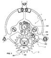
- the anchor 2 is a first piece which, pivotally mounted on a support 4 and around a first axis 200, performs a sustained oscillation movement, which movement makes it possible to split the rotation of a second a piece which, said wheel 3, on the one hand, is rotatably mounted on the support 4, and this, around a second axis 300, parallel to the first axis 200 and, on the other hand, is rotated by a member motor (not shown).
- the anchor 2 and the wheel 3 are flat parts, that is to say that they each have a structural part 201 determined by opposite faces 21 and 22 and a peripheral face 23.
- the pallets 202 are bodies which, in particular made of a hard material, are attached and fixed on the structural part 201 of the anchor 2.
- Each pallet 202 comprises two groups of functional surfaces including, a first group 203 of functional surfaces intended to participate in its attachment to the anchor 2 and a second group 204 of functional surfaces intended to cooperate locally with a face, called the fourth face 302, determining the transverse profile of each tooth 301 of the wheel 3 ( figure 1 ).
- the functional surfaces of the second group 204 are planar surfaces which each extend in a plane parallel to the first axis 200.
- the functional surfaces of the second group 204 are those known as “support plane” and “rest plane”, but this is not limiting.
- one of the functional surfaces of the first group 203 extends in continuity and in the same plane as a functional surface of the second group 204.
- the functional surfaces of the second group 204 must be very precisely positioned relative to the first axis 200, that is to say to the axis which allows the anchor 2 to pivot on the support 4.
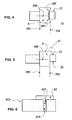
- a device 5 is used to adjust its position by moving the pallet 202 in a direction, called the adjustment direction D1, parallel to said first and second functional surfaces 205, 206 and said first face 21 and second face 22 of the structural part 201,
- the setting device 5 is simply symbolized because it does not relate to the invention.
- This technical feature allows that, when adjusting a pallet 202 by displacement between the pinch bearing surfaces 207, the risk of accidental tilting of the pallet 202 around a third axis 208 orthogonal to said first and second functional surfaces 205, 206, significantly reduced.
- that of said first functional surface 205 and second functional surface 206 which carries said support element 6 comprises a groove 60 whose cross section has a chosen shape so such that groove 60 cooperates with each of the two edges 209 which are formed by the intersection, on the one hand, of that of the bearing surfaces 207 which is intended to cooperate with this functional surface and, on the other hand, of each of said first face 21 and second face 22 of the structural part 201 of the anchor.
- the groove 60 extends over the entire dimension of the pallet 202 in the direction D1 of adjustment.
- the groove 60 can thus be easily obtained by grinding.
- the groove 60 is of rounded cross section, but other shapes may be suitable and by way of example, the groove 60 has a V-shaped cross section.
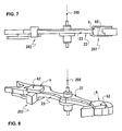
- the pallet 202 carries a heel 61 which bears on one of said first functional surface 205 and second functional surface 206.
- the heel 61 is constituted by a projection of the material which constitutes at least partly the pallet 202, which projection extends beyond at least one of the two surfaces that are the first functional surface 205 and the second functional surface 206, for a distance sufficient to constitute the support element 6.
- the heel 61 is constituted by a projection formed by a plate 62 attached and fixed on the pallet 202, which projection extends beyond at least one of the two surfaces that are the first functional surface 205 and the second functional surface 206, and this, for a distance sufficient to constitute the support element 6.
- the plate 62 is fixed by gluing.
- the pallet 202 and the plate 62 comprise relative positioning means and for example, that of the faces of the pallet 202 which receives the plate 62 comprises a bore 620 and the plate 62 comprises in turn a lug 621 intended for s to fit into the hole 620.
Landscapes
- Physics & Mathematics (AREA)
- General Physics & Mathematics (AREA)
- Jigs For Machine Tools (AREA)
- Pallets (AREA)
Claims (7)
- Anker für Uhrhemmungsmechanismus (1) vom Typ Anker (2) und Rad (3), wobei der Anker (2) angeordnet ist, um schwenkbar auf einem Träger (4) um eine erste Achse (200) montiert zu werden und angeordnet ist, um mit einem Rad (3) zusammenzuarbeiten, das drehend auf dem Träger (4) montiert ist, und dies um eine zweite Achse (300), die parallel zur ersten Achse (200) ist,. wobei der Anker (2) einen strukturellen Teil (201) aufweist, der durch mindestens zwei gegenüberliegende Seiten, genannt erste Seite (21) und zweite Seite (22) bestimmt ist, die flach und orthogonal zur ersten Achse (200) sind, wobei das Rad eine Vielzahl von Zähnen (301) umfasst und der Anker (2) mindestens zwei funktionelle Teile aufweist, die, im Folgenden Paletten (202) genannt,.. dazu bestimmt sind, sequenziell mit den Zähnen (301) zusammenzuarbeiten,.. aus einem harten Material bestehen, am strukturellen Teil (201) des Ankers (2) aufmontiert und befestigt sind,. wobei jede Palette (202) zwei Gruppen von funktionellen Oberflächen umfasst, davon eine erste Gruppe (203) von funktionellen Oberflächen, die dazu bestimmt sind, an ihrer Befestigung auf dem Anker (2) mitzuwirken, und eine zweite Gruppe (204) von funktionellen Oberflächen, die dazu bestimmt sind, lokal mit einer Seite, genannt vierte Seite (302) zusammenzuarbeiten, die das Querprofil jedes Zahns (301) des Rades (3) bestimmt, wobei sich eine der funktionellen Oberflächen der ersten Gruppe (203) kontinuierlich auf einer gleichen Ebene wie eine funktionelle Oberfläche der zweiten Gruppe (204) erstreckt.. wobei auf jeder Palette (202) die erste Gruppe (203) von funktionellen Oberflächen mindestens zwei funktionelle Oberflächen umfasst, die, genannt erste funktionelle Oberfläche (205) und zweite funktionelle Oberfläche (206) einander gegenüberliegen und zueinander parallel sind und das Festhalten der Palette (202), insbesondere durch Klemmen, ermöglichen,. wobei auf dem strukturellen Teil (201) des Ankers (2) für jede Palette (202) eine Gruppe von zwei Auflageflächen (207) vorgesehen ist, die, genannt erste Auflagefläche und zweite Auflagefläche, einerseits einander gegenüberliegend angeordnet sind, jede auf einer orthogonalen Ebene zur ersten Seite (21) und zweiten Seite (22) des strukturellen Teils (201), und, andererseits dazu bestimmt sind, einerseits auf der ersten funktionellen Oberfläche (205) und andererseits auf der zweiten funktionellen Oberfläche (206) aufzuliegen, um ein Klemmen der Palette (202) sicherzustellen,wobei jede Palette (202) angeordnet ist, um bezüglich der ersten Achse (200) und zwischen den Auflageflächen der Klemmung (207) durch Verschiebung der Palette (202) in eine Richtung, genannt Einstellungsrichtung (D1), parallel zur ersten und zweiten funktionellen Oberfläche (205, 206) und zur ersten Seite (21) und zweiten Seite (22) des strukturellen Teils (201) positioniert zu werden.
wobei der Anker dadurch gekennzeichnet ist, dass mindestens eine der funktionellen Oberflächen, d.h. die erste funktionelle Oberfläche (205) und die zweite funktionelle Oberfläche (206) sich nicht kontinuierlich und auf einer gleichen Ebene wie eine funktionelle Oberfläche der zweiten Gruppe (204) erstreckt und mindestens ein Auflageelement (6) trägt, das eine lineare Auflage auf einer der Seiten, d.h. der ersten Seite (21) und der zweiten Seite (22) des strukturellen Teils (201) des Ankers (2) definiert. - Anker nach Anspruch 1, dadurch gekennzeichnet dass, um das Auflageelement (6) zu bilden, diejenige der ersten funktionellen Oberfläche (205) und der zweiten funktionellen Oberfläche (206), die das Auflageelement (6) trägt, eine Nut (60) enthält, deren Querschnitt eine Form aufweist, die so gewählt ist, dass diese Nut (60) mit jeder der zwei Kanten (209) zusammenarbeitet, die aus dem Schnitt einerseits derjenigen der Auflageflächen (207) gebildet sind, die dazu bestimmt ist, mit dieser funktionellen Oberfläche zusammenzuarbeiten, und andererseits jeder der ersten Seite (21) und der zweiten Seite (22) des strukturellen Teils (201) des Ankers.
- Anker nach Anspruch 2, dadurch gekennzeichnet, dass sich die Nut (60) über die gesamte Abmessung der Palette (202) in der Einstellungsrichtung (D1) erstreckt.
- Anker nach Anspruch 2, dadurch gekennzeichnet, dass die Nut (60) einen abgerundeten Querschnitt aufweist.
- Anker nach Anspruch 1, dadurch gekennzeichnet dass, um das Auflageelement (6) zu bilden, die Palette (202) einen Absatz (61) trägt, der auf einer der ersten funktionellen Oberfläche (205) und der zweiten funktionellen Oberfläche (206) aufliegt.
- Anker nach Anspruch 5, dadurch gekennzeichnet dass der Absatz (61) durch einen Vorsprung des Materials gebildet ist, das die Palette (202) mindestens teilweise bildet, wobei sich der Vorsprung über mindestens eine der zwei Oberflächen, d.h. die erste funktionelle Oberfläche (205) und die zweite funktionelle Oberfläche (206) hinaus erstreckt, und dies auf einer Distanz, die ausreichend ist, um das Auflageelement (6) zu bilden.
- Anker nach Anspruch 5, dadurch gekennzeichnet dass der Absatz (61) durch einen Vorsprung des Materials gebildet ist, der aus einer festen Platte auf der Palette (202) besteht, wobei sich der Vorsprung über mindestens eine der zwei funktionellen Oberflächen, d.h. die erste funktionelle Oberfläche (205) und die zweit funktionelle Oberfläche (206) hinaus erstreckt, und dies auf einer Distanz, die ausreichend ist, um das Auflageelement (6) zu bilden.
Priority Applications (2)
| Application Number | Priority Date | Filing Date | Title |
|---|---|---|---|
| DE200760003434 DE602007003434D1 (de) | 2007-03-01 | 2007-03-01 | Anker für Uhrhemmungsmechanismus vom Typ Anker und Rad |
| EP20070103341 EP1965277B1 (de) | 2007-03-01 | 2007-03-01 | Anker für Uhrhemmungsmechanismus vom Typ Anker und Rad |
Applications Claiming Priority (1)
| Application Number | Priority Date | Filing Date | Title |
|---|---|---|---|
| EP20070103341 EP1965277B1 (de) | 2007-03-01 | 2007-03-01 | Anker für Uhrhemmungsmechanismus vom Typ Anker und Rad |
Publications (2)
| Publication Number | Publication Date |
|---|---|
| EP1965277A1 EP1965277A1 (de) | 2008-09-03 |
| EP1965277B1 true EP1965277B1 (de) | 2009-11-25 |
Family
ID=38982649
Family Applications (1)
| Application Number | Title | Priority Date | Filing Date |
|---|---|---|---|
| EP20070103341 Ceased EP1965277B1 (de) | 2007-03-01 | 2007-03-01 | Anker für Uhrhemmungsmechanismus vom Typ Anker und Rad |
Country Status (2)
| Country | Link |
|---|---|
| EP (1) | EP1965277B1 (de) |
| DE (1) | DE602007003434D1 (de) |
Family Cites Families (3)
| Publication number | Priority date | Publication date | Assignee | Title |
|---|---|---|---|---|
| CH357337A (de) * | 1959-09-30 | 1961-09-30 | Ebauchesfabrik Eta Ag | Anker für Uhrwerk |
| CH541666A4 (de) * | 1966-04-14 | 1968-02-29 | ||
| JPS57110979A (en) * | 1980-12-27 | 1982-07-10 | Citizen Watch Co Ltd | Precision part with solid-lubricated sliding surface |
-
2007
- 2007-03-01 EP EP20070103341 patent/EP1965277B1/de not_active Ceased
- 2007-03-01 DE DE200760003434 patent/DE602007003434D1/de active Active
Also Published As
| Publication number | Publication date |
|---|---|
| EP1965277A1 (de) | 2008-09-03 |
| DE602007003434D1 (de) | 2010-01-07 |
Similar Documents
| Publication | Publication Date | Title |
|---|---|---|
| EP1704448B1 (de) | Gezähntes drehteil für die einholung des spiels, getriebe, und die benutzung dieses getriebes | |
| EP2977829B1 (de) | Anordnung mit beweglichem Bremselement einer Uhr | |
| EP2743782B1 (de) | Vorrichtung zum zusammenbau von elastischen armen durch verformung | |
| FR2688163A1 (fr) | Dispositif d'entretoisement pour les lames d'un train de scies et train de scies utilisant un tel dispositif. | |
| EP1826634A1 (de) | Mikromechanisches Bauteil mit formschlüssiger Öffnung zum Assemblieren einer Welle | |
| EP3483663B1 (de) | Antriebsvorrichtung für kalendersystem einer uhr | |
| EP2977833B1 (de) | Präzise Positionierung der Brücke einer Uhr | |
| EP2798413B1 (de) | Feder für uhrwerk | |
| EP2781972B1 (de) | Zapfen für Uhrwerksmechanismus | |
| EP1978421A2 (de) | Gestellelement für Uhren | |
| CH707808B1 (fr) | Cassette de mécanisme d'horlogerie. | |
| EP3489766B1 (de) | Mechanismus zur korrektur einer bewegungsfunktion einer uhr | |
| EP1965277B1 (de) | Anker für Uhrhemmungsmechanismus vom Typ Anker und Rad | |
| EP2798414B1 (de) | Feder für uhrwerk | |
| CH716957A2 (fr) | Dispositif de guidage pour afficheur d'horlogerie. | |
| EP2781971B1 (de) | Struktur für Uhrwerksmechanismus | |
| EP2075652A1 (de) | Antriebs- und Übertragungsorgan für einen Hemmungsmechanimus, damit ausgestattete Platte und Hemmung und mit diesen ausgestattetes Uhrwerk | |
| CH709282A2 (fr) | Ancre suspendue pour échappement horloger. | |
| EP1923754B1 (de) | Mit einem Anzeigemodul ausgerüstetes Uhrwerk | |
| EP1860511B1 (de) | Uhrwerk mit einer mobilen Brücke | |
| CH714791A1 (fr) | Organe denté pour pièce d'horlogerie. | |
| CH716774B9 (fr) | Dispositif horloger de couplage et d'indexation. | |
| EP3629100B1 (de) | Vorrichtung zur symmetrischen führung von zwei elementen, insbesondere für uhrwerke | |
| EP3432080A1 (de) | Uhrwerksbestandteil | |
| EP4184254B1 (de) | Armbanduhrengehäuse mit einer verriegelung |
Legal Events
| Date | Code | Title | Description |
|---|---|---|---|
| PUAI | Public reference made under article 153(3) epc to a published international application that has entered the european phase |
Free format text: ORIGINAL CODE: 0009012 |
|
| AK | Designated contracting states |
Kind code of ref document: A1 Designated state(s): AT BE BG CH CY CZ DE DK EE ES FI FR GB GR HU IE IS IT LI LT LU LV MC MT NL PL PT RO SE SI SK TR |
|
| AX | Request for extension of the european patent |
Extension state: AL BA HR MK RS |
|
| 17P | Request for examination filed |
Effective date: 20090129 |
|
| 17Q | First examination report despatched |
Effective date: 20090304 |
|
| AKX | Designation fees paid |
Designated state(s): CH DE LI |
|
| GRAP | Despatch of communication of intention to grant a patent |
Free format text: ORIGINAL CODE: EPIDOSNIGR1 |
|
| RTI1 | Title (correction) |
Free format text: PALLETS FOR A TIMEPIECE ESCAPEMENT MECHANISM OF PALLETS AND WHEEL TYPE |
|
| GRAS | Grant fee paid |
Free format text: ORIGINAL CODE: EPIDOSNIGR3 |
|
| GRAA | (expected) grant |
Free format text: ORIGINAL CODE: 0009210 |
|
| AK | Designated contracting states |
Kind code of ref document: B1 Designated state(s): CH DE LI |
|
| REG | Reference to a national code |
Ref country code: CH Ref legal event code: EP |
|
| REG | Reference to a national code |
Ref country code: CH Ref legal event code: NV Representative=s name: BOVARD AG PATENTANWAELTE |
|
| REF | Corresponds to: |
Ref document number: 602007003434 Country of ref document: DE Date of ref document: 20100107 Kind code of ref document: P |
|
| PLBE | No opposition filed within time limit |
Free format text: ORIGINAL CODE: 0009261 |
|
| STAA | Information on the status of an ep patent application or granted ep patent |
Free format text: STATUS: NO OPPOSITION FILED WITHIN TIME LIMIT |
|
| 26N | No opposition filed |
Effective date: 20100826 |
|
| REG | Reference to a national code |
Ref country code: CH Ref legal event code: PFA Owner name: AUDEMARS PIGUET (RENAUD ET PAPI) SA Free format text: AUDEMARS PIGUET (RENAUD ET PAPI) SA#RUE JAMES-PELLATON 2#2400 LE LOCLE (CH) -TRANSFER TO- AUDEMARS PIGUET (RENAUD ET PAPI) SA#RUE JAMES-PELLATON 2#2400 LE LOCLE (CH) |
|
| PGFP | Annual fee paid to national office [announced via postgrant information from national office to epo] |
Ref country code: DE Payment date: 20170322 Year of fee payment: 11 Ref country code: CH Payment date: 20170313 Year of fee payment: 11 |
|
| REG | Reference to a national code |
Ref country code: DE Ref legal event code: R119 Ref document number: 602007003434 Country of ref document: DE |
|
| REG | Reference to a national code |
Ref country code: CH Ref legal event code: PL |
|
| PG25 | Lapsed in a contracting state [announced via postgrant information from national office to epo] |
Ref country code: DE Free format text: LAPSE BECAUSE OF NON-PAYMENT OF DUE FEES Effective date: 20181002 |
|
| PG25 | Lapsed in a contracting state [announced via postgrant information from national office to epo] |
Ref country code: LI Free format text: LAPSE BECAUSE OF NON-PAYMENT OF DUE FEES Effective date: 20180331 Ref country code: CH Free format text: LAPSE BECAUSE OF NON-PAYMENT OF DUE FEES Effective date: 20180331 |