EP1964697B1 - Algorithme pour l'activation d'un système de purge dirigé à partir d'accéléromètres de véhicule lors de la collision - Google Patents
Algorithme pour l'activation d'un système de purge dirigé à partir d'accéléromètres de véhicule lors de la collision Download PDFInfo
- Publication number
- EP1964697B1 EP1964697B1 EP07122535A EP07122535A EP1964697B1 EP 1964697 B1 EP1964697 B1 EP 1964697B1 EP 07122535 A EP07122535 A EP 07122535A EP 07122535 A EP07122535 A EP 07122535A EP 1964697 B1 EP1964697 B1 EP 1964697B1
- Authority
- EP
- European Patent Office
- Prior art keywords
- leakage
- probability
- deceleration
- relationship
- predetermined conditions
- Prior art date
- Legal status (The legal status is an assumption and is not a legal conclusion. Google has not performed a legal analysis and makes no representation as to the accuracy of the status listed.)
- Ceased
Links
Images


Classifications
-
- B—PERFORMING OPERATIONS; TRANSPORTING
- B60—VEHICLES IN GENERAL
- B60H—ARRANGEMENTS OF HEATING, COOLING, VENTILATING OR OTHER AIR-TREATING DEVICES SPECIALLY ADAPTED FOR PASSENGER OR GOODS SPACES OF VEHICLES
- B60H1/00—Heating, cooling or ventilating devices
- B60H1/00642—Control systems or circuits; Control members or indication devices for heating, cooling or ventilating devices
- B60H1/00978—Control systems or circuits characterised by failure of detection or safety means; Diagnostic methods
-
- Y—GENERAL TAGGING OF NEW TECHNOLOGICAL DEVELOPMENTS; GENERAL TAGGING OF CROSS-SECTIONAL TECHNOLOGIES SPANNING OVER SEVERAL SECTIONS OF THE IPC; TECHNICAL SUBJECTS COVERED BY FORMER USPC CROSS-REFERENCE ART COLLECTIONS [XRACs] AND DIGESTS
- Y02—TECHNOLOGIES OR APPLICATIONS FOR MITIGATION OR ADAPTATION AGAINST CLIMATE CHANGE
- Y02T—CLIMATE CHANGE MITIGATION TECHNOLOGIES RELATED TO TRANSPORTATION
- Y02T10/00—Road transport of goods or passengers
- Y02T10/80—Technologies aiming to reduce greenhouse gasses emissions common to all road transportation technologies
- Y02T10/84—Data processing systems or methods, management, administration
Definitions
- the subject invention relates to an air conditioning system, and more specifically, to a method of venting a refrigerant from the air conditioning system of a vehicle during a crash to mitigate leakage of the refrigerant into a cabin of the vehicle.
- Air conditioning systems with directed relief valves for venting refrigerant are well known in the art.
- An example of such a system is disclosed in the U.S. Pat. No. 6,085,531 (the '531 patent) to Numoto et al.
- the '531 patent discloses an air conditioning system utilizing a flammable refrigerant, such as propane.
- the system includes the standard components of a compressor, a condenser, an expansion device, and an evaporator.
- the system also includes a sensor to continuously monitor leakage of the refrigerant, particularly in an air space. When a leak is detected, the sensor generates a signal.
- a directed relief valve receives the signal and opens the valve in response to the signal to vent the refrigerant to the surrounding atmosphere.
- venting refrigerant contained within an air conditioning system after a leak is detected helps to prevent exposure to the refrigerant contained within the air conditioning system to the occupants of a vehicle, it does not prevent exposure to the refrigerant that has already leaked from the air conditioning system.
- the integrity of the air conditioning system can be severely compromised in an instant, causing refrigerant to leak from the air conditioning system before the refrigerant can be vented to the surrounding atmosphere.
- the directed relief system controlling the directed relief valve may become damaged entirely, thus preventing the directed relief valve from venting the refrigerant still contained within the air conditioning system.
- the '738 patent discloses a refrigerant relief device for an air conditioning system having a sensor.
- a sensor senses deceleration of the vehicle greater than a predetermined threshold amount, for example, an impact due to a collision of the vehicle, a CPU supplies current to a relief valve, discharging the refrigerant from the air conditioning system.
- the U.S. Patent No. 5,684,701 discloses a sensor system for initiating deployment of an occupant protection apparatus in a vehicle, such as an air bag, to protect an occupant of the vehicle in a crash.
- a neural network is trained using data from approximately 25 crash events, and in addition, techniques of velocity and crash scaling are used to create a large library of crashes.
- a sensor senses deceleration of the vehicle, and the neural network determines if the signal contains a pattern characteristic of a vehicle crash by directly comparing the signal to the library of crash events. If the neural network determines the signal from the sensor is similar to a stored signal in the library of crash events, a deployment initiation mechanism initiates deployment of the occupant protection apparatus.
- the invention provides a method of venting a refrigerant from an air conditioning system of a vehicle during a crash to mitigate leakage into a cabin of the vehicle.
- the method comprises the steps of crashing a test vehicle having an air conditioning test system under a first set of predetermined conditions a number of first crash events, determining the existence of leakage of a test refrigerant from the air conditioning test system during each of the number of first crash events, dividing the number of first crash events in which leakage of the test refrigerant under the first set of predetermined conditions existed by the number of first crash events to establish a first probability of leakage ratio, crashing the test vehicle under a second set of predetermined conditions a number of second crash events, determining the existence of leakage of the test refrigerant from the air conditioning test system each of the number of second crash events, dividing the number of second crash events in which leakage of the test refrigerant under the second set of predetermined conditions existed by the number of second crash events to establish a second probability of leakage ratio, correlating the
- the method will sense a condition of a vehicle to determine a probability of leakage ratio from a probability of leakage relationship in order to vent the refrigerant from the air conditioning system when the probability of leakage ratio exceeds a predetermined threshold before the occurrence of the crash event.
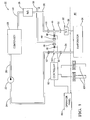
- Figure 1 is a schematic view of a first embodiment of an air conditioning system showing a thermostatic expansion valve implemented as an expansion device;
- Figure 2 is a schematic view of a second embodiment of the air conditioning system showing an orifice tube implemented as the expansion device;
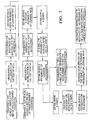
- Figure 3 is a flowchart showing an algorithm for venting a refrigerant from an air conditioning system of a vehicle
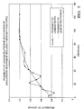
- Figure 4 is a graph of a first embodiment of the probability of leakage relationship
- Figure 5 is a graph of a second embodiment of the probability of leakage relationship.
- FIG. 3 a method of venting a refrigerant from an air conditioning system 20 of a vehicle is shown in Figure 3 .
- An example of such an air conditioning system is shown at 20 in Figure 1 .
- the method may be used to vent alternative air conditioning systems 20.
- the air conditioning system 20 is located in a vehicle.
- the air conditioning system 20 is implemented into a building, an industrial cooling system, a refrigerator, etc.
- the air conditioning system 20 utilizes a refrigerant.
- the refrigerant is of type R-152a or carbon dioxide (CO 2 ).
- CO 2 carbon dioxide
- refrigerants include, but are not limited to R-12/CFC-12, R-134a/HFC-134a, isobutane, and propane.
- a compressor 22 is operatively connected to a suction line 24.
- the suction line 24 contains the refrigerant in a low pressure, gaseous state.
- the compressor 22 receives the refrigerant from the suction line 24 and compresses the refrigerant into a high-pressure gaseous state.
- a gas line 26 is operatively connected to the compressor 22 for receiving the refrigerant and transporting it along in the system.
- a condenser 28 or gas cooler is operatively connected to the gas line 26.
- the condenser 28 cools the refrigerant received from the gas line 26.
- the condenser 28 dissipates heat removed from the refrigerant to the environment.
- a liquid line 30 is operatively connected to the condenser 28 for receiving the refrigerant from the condenser 28.
- An expansion device 32 is operatively connected to the liquid line 30.
- An evaporator 34 is also operatively connected to the expansion device 32.
- the expansion device 32 restricts the flow of the refrigerant using the Joules-Thompson effect to significantly cool and lower the pressure of the refrigerant before entering the evaporator 34.
- a thermostatic expansion valve (TXV) 36 performs the function of the expansion device 32.
- the TXV 36 dynamically regulates the flow of refrigerant into the evaporator 34.
- a receiver/dryer 38 is typically connected in-line with the liquid line 30.
- the receiver/dryer may be integrated into the condenser.
- an orifice tube 40 is used as a static, fixed implementation of the expansion device 32.
- An accumulator/dehydrator 42 is implemented in-line with the suction line 24 in the second embodiment.
- the evaporator 34 is preferably located within an air space 44 and includes a series of coils. As air flows through the air space 44 and the evaporator 34, it is cooled by heat exchange with the coils of the evaporator 34.
- the evaporator 34 is also operatively connected to the suction line 24 for sending the now low-pressure, mostly gaseous refrigerant back to the compressor 22.
- a first directed relief valve 46 is integrated with the air conditioning system 20 in order to vent the refrigerant to the atmosphere.
- the first directed relief valve 46 includes an ambient port 48 open to the atmosphere.
- the first directed relief valve 46 also includes an inlet 50 for receiving the refrigerant and an outlet 52 for sending the refrigerant.
- the inlet 50 and outlet 52 are operatively connected inline to one of the lines 24, 26, 30, such as the suction line 24, the gas line 26, or the liquid line 30.
- Additional directed relief valves, such as a second directed relief valve 54 may also be implemented in the system.
- the embodiments shown in Figures 1 and 2 illustrate the first directed relief valve 46 in-line with the liquid line 30 and the second directed relief valve 54 in-line with the suction line 24.
- Those skilled in the art realize that alternate locations and quantities of the directed relief valves 46, 54 are possible. However, for ease of illustration, only the first directed relief valve 46 will be described hereforth.
- a squib 56 is positioned within the first directed relief valve 46 to block the inlet 50 and the outlet 52 from the ambient port 48.
- refrigerant enters the inlet 50 and flows out the outlet 52; no refrigerant flows to the ambient port 48.
- the squib 56 detonates and deflagrates, thus unblocking the inlet 50 and the outlet 52 from the ambient port 48. Refrigerant then flows in through the inlet 50 and the outlet 52 to the ambient port 48.
- the ambient port 48 is preferably connected to a port tube 58.
- the port tube 58 leads to a location away from the air space 44 for venting the refrigerant to the atmosphere.
- venting the refrigerant from the system takes about six to ten seconds. Venting of the refrigerant may be required for a number of reasons, including, but not limited to, potential toxicity or flammability related to the refrigerant.
- the air conditioning system 20 uses a sensor 60 for sensing a condition of the vehicle to determine the probability of leakage ratio.
- the sensor 60 senses a condition and produces a sensor 60 signal in response to sensing the condition.
- Various types of conditions can be sensed, including, but not limited to, deceleration, impact, or front end crush. Depending on the reliability and sensing needs of the sensor 60, additional sensors 60 may be required.
- a controller 62 is electrically connected to the sensor 60 and the squib 56.
- the controller 62 contains all the necessary electrical and electronic components to perform its function as described herein. These components include, but are not limited to, a power supply, a microprocessor, an analog-to-digital converter, an amplifier, and a relay.
- the controller 62 receives a sensor 60 signal from the sensor 60.
- the controller 62 analyzes the sensor 60 signal by evaluating a relationship with the current value of the sensor 60, comparing the current value to a lookup table, or comparing the current value to any other set of predetermined values stored within the controller 62. In analyzing the sensor 60 signal, the controller 62 determines the probability of leakage ratio.
- the controller 62 In response to the probability of leakage ratio exceeding a predetermined threshold, the controller 62 sends a venting signal to the squib 56.
- the squib 56 then initiates an opening by deflagrating, causing the refrigerant to be vented from the system to the atmosphere.
- the method of venting a refrigerant from the air conditioning system 20 of a vehicle is shown in Figure 3 and consists of the step of crashing a test vehicle having an air conditioning test system under a first set of predetermined conditions a number of first crash events. These tests are preferably done in conjunction with crash tests done for other purposes, such as vehicle crashworthiness tests or airbag evaluations.
- the predetermined conditions can be, but are not limited to, velocity, offset, barrier type and geometry, or impact sled.
- the test vehicle is preferably of the same type as the vehicle, however, test vehicles differing from the vehicle can also be used.
- the method includes the step of measuring a deceleration of the test vehicle each of the number of first crash events to establish a number of first deceleration measurements.
- the method includes the step of determining the existence of leakage of a test refrigerant from the air conditioning test system each of the number of first crash events.
- determining the existence of leakage all forms of leakage can be considered, or only those leaks that do not result from a puncture can be considered.
- There are ways to mitigate punctures in an air conditioning system including different, softer grille plastics that do not result in sharp objects when broken and rounding of sharp metal edges in front of a condenser, especially on the hood latch. Therefore, depending upon whether the original equipment manufactures consider design modifications to reduce punctures, the determining of the existence of leakage can either include or ignore leakage as a result of punctures.
- the types of leaks considered will remain constant throughout the number of first crash events.
- the method includes the step of dividing the number of first crash events in which leakage of the test refrigerant under the first set of predetermined conditions existed by the number of first crash events to establish a first probability of leakage ratio.
- the method includes the step of crashing the test vehicle under a second set of predetermined conditions a number of second crash events.
- the test vehicle is preferably of the same kind as the test vehicle crashed under the first set of predetermined conditions, but a test vehicle of a different kind may also be used to provide general test crash results covering a wide range of vehicles.
- the test vehicle crashed under the second crash events is of the same kind as the test vehicle crashed under the first set of predetermined conditions, and the test vehicles are of the same kind as the vehicle.
- the method includes the step of measuring the deceleration of the test vehicle each of the number of second crash events to establish a number of second deceleration measurements.
- the method includes the step of determining the existence of leakage of the test refrigerant from the air conditioning test system each of the number of second crash events.
- determining the existence of leakage of the number of second crash events all forms of leakage can be considered, or only those leaks that do not result from a puncture can be considered.
- There are ways to mitigate punctures in an air conditioning system including different, softer grille plastics that do not result in sharp objects when broken and rounding of sharp metal edges in front of a condenser, especially on the hood latch. Therefore, depending upon whether the original equipment manufactures consider design modifications to reduce punctures, the determining of the existence of leakage can either include or ignore leakage as a result of punctures.
- leakage as a result of punctures was excluded, however, in the embodiment shown in Figure 5 , leakage as a result of punctures was included.
- the types of leaks considered will remain constant throughout the number of second crash events, and preferably the types of leaks considered under the number of second crash events are the same as those considered under the number of first crash events.
- the method includes the step of dividing the number of second crash events in which leakage of the test refrigerant under the second set of predetermined conditions existed by the number of second crash events to establish a second probability of leakage ratio
- the method includes the step of correlating the predetermined conditions and the probability of leakage ratios to establish a probability of leakage relationship.
- the step of correlating the predetermined conditions and the probability of leakage ratios to establish a probability of leakage relationship is further defined as establishing a graph with the predetermined conditions on an x-axis and the probability of leakage ratios on a y-axis, placing the probability of leakage ratios on the graph as shown in Figures 4 , and establishing a probability of leakage relationship of the probability of leakage ratios.
- the probability of leakage relationship can be, but is not limited to, being a polynomial regression of the probability of leakage ratios.
- the probability of leakage relationship is established as being a third order polynomial regression of the probability of leakage ratios relating the predetermined condition, front end crush in this embodiment, to the probability of leakage.
- the method includes the step of correlating the deceleration measurements of the test vehicle and the predetermined conditions to establish a deceleration relationship to the probability of leakage ratios.
- the step of correlating the deceleration measurements of the test vehicle and the predetermined conditions to establish a deceleration relationship to the probability of leakage ratios can be further defined as establishing a trigger graph with the deceleration measurements of the test vehicle on a trigger x-axis and the predetermined conditions on a trigger y-axis, placing the deceleration measurements on the trigger graph, and establishing the deceleration relationship of the deceleration measurements to the probability of leakage relationship.
- correlating the deceleration measurements of the test vehicle to the predetermined conditions will establish a deceleration relationship whereby the predetermined conditions are expressed as a function of deceleration.
- the probability of leakage relationship expressed as the probability of leakage being a function of the predetermined conditions, can thereby be simplified to further define the probability of leakage relationship as being the probability of leakage being a function of the deceleration relationship as shown in Figure 5 .
- the step of correlating the deceleration measurements of the test vehicle and the predetermined conditions to establish a deceleration relationship to the probability of leakage ratios can be further defined as establishing a table to correlate the deceleration measurements and the predetermined conditions to establish the deceleration relationship to the probability of leakage ratios.
- a condition other than deceleration such as, but not limited to, impact or front end crush is measured of the test vehicle during the first and second crash events. The condition is correlated with the predetermined conditions to establish a condition relationship to the probability of leakage ratios.
- the method includes the step of sensing a condition of the vehicle to determine the probability of leakage ratio from the probability of leakage relationship.
- the condition sensed is deceleration.
- the condition sensed is, but is not limited to, impact or front end crush.
- the method includes the step of venting the refrigerant from the air conditioning system 20 in response to the probability of leakage ratio exceeding a predetermined threshold.
- the original equipment manufacturer sets the air conditioning system 20 to vent the refrigerant based on a trade-off between the probability of having the air conditioning system 20 functional in a drivable post-crash vehicle versus mitigating the risk by discharging the refrigerant. It is most accurate if an original equipment manufacturer plots out the probability of refrigerant leakage versus the predetermined conditions for each of their car platforms or constructions. However, if an original equipment manufacturer does not have enough data to do this, the curves generated in Figure 4 and Figure 5 based on a random post-collision vehicle sample is the next best alternative.
Landscapes
- Physics & Mathematics (AREA)
- Thermal Sciences (AREA)
- Engineering & Computer Science (AREA)
- Mechanical Engineering (AREA)
- Air Conditioning Control Device (AREA)
- Air Bags (AREA)
- Air-Conditioning For Vehicles (AREA)
Claims (20)
- Procédé pour purger un réfrigérant depuis un système de conditionnement d'air (20) d'un véhicule pendant une collision pour éviter des fuites dans une cabine du véhicule, ledit procédé comprenant les étapes consistant à :amener un véhicule test ayant un système de conditionnement d'air test en collision pour un nombre de premiers événements de collision sous un premier groupe de conditions prédéterminées,déterminer l'existence d'une fuite d'un réfrigérant test depuis le système de conditionnement d'air test à chacun du nombre de premiers événements de collision,diviser le nombre de premiers événements de collision dans lesquels une fuite du réfrigérant test s'est produite sous le premier groupe de conditions prédéterminées par le nombre de premiers événements de collision pour établir une première probabilité de rapport de fuite,amener le véhicule test en collision pour un nombre de seconds événements de collision sous un second groupe de conditions prédéterminées,déterminer l'existence d'une fuite du réfrigérant test hors du système de conditionnement d'air test à chacun du nombre de seconds événements de collision,diviser le nombre de seconds événements de collision dans lesquels une fuite du réfrigérant test s'est produite sur le second groupe de conditions prédéterminées par le nombre de seconds événements de collision pour établir une seconde probabilité de rapport de fuite,mettre en corrélation les conditions prédéterminées et la probabilité de rapport de fuite pour établir une probabilité de relation de fuite,détecter une condition du véhicule pour déterminer une probabilité de rapport de fuite à partir de la probabilité de relation de fuite, etpurger le réfrigérant hors du système de conditionnement d'air (20) en réponse au fait que la probabilité de rapport de fuite excède un seuil prédéterminé.
- Procédé selon la revendication 1, dans lequel ladite étape de mise en corrélation des conditions prédéterminées et de la probabilité de rapports de fuite pour établir une probabilité de relation de fuite est encore définie comme consistant à :établir un graphique avec les conditions prédéterminées sur un axe x et la probabilité des rapports de fuite sur un axe y,placer la probabilité des rapports de fuite sur le graphique, etétablir la probabilité de relation de fuite de la probabilité de rapports de fuite.
- Procédé selon la revendication 2, dans lequel la probabilité de rapport de fuite est encore définie comme étant une régression polynomiale de la probabilité de rapports de fuite.
- Procédé selon la revendication 3, dans lequel la probabilité de relation de fuite est encore définie par

dans laquelle y est la probabilité de rapport de fuite et x représente les conditions prédéterminées. - Procédé selon la revendication 3, dans lequel la probabilité de relation de fuite est encore définie par

dans laquelle y est la probabilité de rapport de fuite et x représente les conditions prédéterminées. - Procédé selon la revendication 1, incluant les étapes consistant à mesurer une décélération du véhicule test à chacun des premiers événements de collision pour établir un nombre de premières mesures de décélération et à mesurer la décélération du véhicule test à chacun des seconds événements de collision pour établir un nombre de secondes mesures de décélération.
- Procédé selon la revendication 6, incluant l'étape consistant à mettre en corrélation les mesures de décélération du véhicule test et les conditions prédéterminées pour établir une relation de décélération vis-à-vis de la probabilité de rapports de fuite.
- Procédé selon la revendication 7, dans lequel ladite étape de mise en corrélation des mesures de décélération est encore définie comme consistant à :établir un graphique de déclenchement avec les mesures de décélération du véhicule test sur un axe x de déclenchement et les conditions prédéterminées sur un axe y de déclenchement,placer les mesures de décélération sur le graphique de déclenchement, etétablir la relation de décélération des mesures de décélération.
- Procédé selon la revendication 8, dans lequel la relation de décélération vis-à-vis de la probabilité de rapports de fuite est encore définie comme étant une régression polynomiale des mesures de décélération.
- Procédé selon la revendication 7, dans lequel ladite étape de mise en corrélation des mesures de décélération est encore définie comme consistant à établir une table pour mettre en corrélation les mesures de décélération et les conditions prédéterminées pour établir la relation de décélération vis-à-vis de la probabilité de rapports de fuite.
- Procédé selon la revendication 7, dans lequel ladite mise en corrélation des conditions prédéterminées et de la probabilité de rapports de fuite pour établir une probabilité de relation de fuite est encore définie comme consistant à :établir un graphique avec les conditions prédéterminées sur un axe x et la probabilité de rapports de fuite sur un axe y,placer la probabilité de rapports de fuite sur le graphique, etétablir la probabilité de relation de fuite vis-à-vis de la probabilité de rapports de fuite.
- Procédé selon la revendication 11, dans lequel la probabilité de relation de fuite est encore définie comme étant une régression polynomiale de la probabilité de rapports de fuite.
- Procédé selon la revendication 12, dans lequel la probabilité de relation de fuite est encore définie par

dans laquelle y est la probabilité de rapport de fuite et x est la relation de décélération qui met en corrélation la décélération du véhicule et les conditions prédéterminées. - Procédé selon la revendication 12, dans lequel la probabilité de relation de fuite est encore définie par

dans laquelle y est la probabilité de rapport de fuite et x est la relation de décélération qui met en corrélation la décélération du véhicule et les conditions prédéterminées. - Procédé selon la revendication 11, dans lequel ladite étape de détection d'une condition du véhicule est encore définie comme consistant à détecter la décélération du véhicule pour déterminer une probabilité de rapport de fuite à partir de la relation de décélération.
- Procédé pour purger un réfrigérant depuis un système de conditionnement d'air (20) d'un véhicule pendant une collision pour éviter des fuites dans une cabine du véhicule, ledit procédé comprenant les étapes consistant à :amener un véhicule test ayant un système de conditionnement d'air test en collision pour un nombre de premiers événements de collision sous un premier groupe de conditions prédéterminées,mesurer une décélération du véhicule test à chacun du nombre de premiers événements de collision pour établir un nombre de premières mesures de décélération,déterminer l'existence d'une fuite d'un réfrigérant test depuis le système de conditionnement d'air test à chacun du nombre de premiers événements de collision,diviser le nombre de premiers événements de collision dans lesquels une fuite du réfrigérant test s'est produite sous le premier groupe de conditions prédéterminées par le nombre de premiers événements de collision pour établir une première probabilité de rapport de fuite,amener le véhicule test en collision pour un nombre de seconds événements de collision sous un second groupe de conditions prédéterminées,mesurer la décélération du véhicule test à chacun du nombre de seconds événements de collision pour établir un nombre de secondes mesures de décélération,déterminer l'existence d'une fuite du réfrigérant test hors du système de conditionnement d'air test à chacun du nombre de seconds événements de collision,diviser le nombre de seconds événements de collision dans lesquels une fuite du réfrigérant test s'est produite sur le second groupe de conditions prédéterminées par le nombre de seconds événements de collision pour établir une seconde probabilité de rapport de fuite,établir un graphique avec les conditions prédéterminées sur un axe x et la probabilité de rapports de fuite sur un axe y,placer la probabilité de rapports de fuite sur le graphique,établir un une probabilité de relations de fuite qui est une régression polynomiale de la probabilité de rapport de fuite,mettre en corrélation les conditions prédéterminées et les conditions prédéterminées pour établir une relation de décélération vis-à-vis de la probabilité de rapports de fuite,détecter une condition du véhicule pour déterminer une probabilité de rapport de fuite à partir de la relation de décélération, etpurger le réfrigérant hors du système de conditionnement d'air (20) en réponse au fait que la probabilité de rapport de fuite excède un seuil prédéterminé.
- Procédé selon la revendication 16, dans lequel la probabilité de relation de fuite est encore définie par

dans laquelle y est la probabilité de rapport de fuite et x est la relation de décélération qui met en corrélation la décélération du véhicule et les conditions prédéterminées. - Procédé selon la revendication 16, dans lequel la probabilité de relation de fuite est encore définie par

dans laquelle y est la probabilité de rapport de fuite et x est la relation de décélération qui met en corrélation la décélération du véhicule et les conditions prédéterminées. - Procédé selon la revendication 16, dans lequel ladite étape de mise en corrélation de la décélération du véhicule test et des conditions prédéterminées pour établir une relation de décélération vis-à-vis de la probabilité de rapports de fuite est encore définie comme consistant à :établir un graphique de déclenchement avec les mesures de décélération du véhicule test sur un axe x de déclenchement et les conditions prédéterminées sur un axe y de déclenchement,placer les mesures de décélération sur le graphique de déclenchement, etétablir la relation de décélération vis-à-vis de la probabilité de rapports de fuite, dans laquelle la relation de décélération est une régression polynomiale des mesures de décélération.
- Procédé selon la revendication 16, dans lequel ladite étape de mise en corrélation de la décélération du véhicule et des conditions prédéterminées pour établir une relation de décélération vis-à-vis de la probabilité de rapports de fuite est encore définie comme consistant à établir une table pour mettre en corrélation les mesures de décélération et les conditions prédéterminées pour établir la relation de décélération vis-à-vis de la probabilité de rapports de fuite.
Applications Claiming Priority (1)
| Application Number | Priority Date | Filing Date | Title |
|---|---|---|---|
| US11/712,320 US7677049B2 (en) | 2007-02-28 | 2007-02-28 | Algorithm for activation of directed relief system from vehicle accelerometers during crash |
Publications (3)
| Publication Number | Publication Date |
|---|---|
| EP1964697A2 EP1964697A2 (fr) | 2008-09-03 |
| EP1964697A3 EP1964697A3 (fr) | 2009-03-18 |
| EP1964697B1 true EP1964697B1 (fr) | 2010-03-10 |
Family
ID=39233015
Family Applications (1)
| Application Number | Title | Priority Date | Filing Date |
|---|---|---|---|
| EP07122535A Ceased EP1964697B1 (fr) | 2007-02-28 | 2007-12-06 | Algorithme pour l'activation d'un système de purge dirigé à partir d'accéléromètres de véhicule lors de la collision |
Country Status (4)
| Country | Link |
|---|---|
| US (1) | US7677049B2 (fr) |
| EP (1) | EP1964697B1 (fr) |
| AT (1) | ATE460299T1 (fr) |
| DE (1) | DE602007005216D1 (fr) |
Families Citing this family (5)
| Publication number | Priority date | Publication date | Assignee | Title |
|---|---|---|---|---|
| EP2409874A1 (fr) * | 2010-07-21 | 2012-01-25 | BIOTRONIK SE & Co. KG | Système de surveillance pouvant être commandé |
| US9309982B2 (en) | 2011-08-17 | 2016-04-12 | Hitachi, Ltd. | Vehicle device temperature adjustment system |
| US20190186769A1 (en) * | 2017-12-18 | 2019-06-20 | Heatcraft Refrigeration Products Llc | Cooling system |
| JP6729674B2 (ja) * | 2018-12-21 | 2020-07-22 | ダイキン工業株式会社 | コンテナ用冷凍装置 |
| CN109781445B (zh) * | 2018-12-28 | 2020-07-14 | 大连理工大学 | 一种确定热力膨胀阀流通面积的方法 |
Family Cites Families (6)
| Publication number | Priority date | Publication date | Assignee | Title |
|---|---|---|---|---|
| US5684701A (en) * | 1995-06-07 | 1997-11-04 | Automotive Technologies International, Inc. | Method and apparatus for sensing a vehicle crash |
| JP3775920B2 (ja) * | 1998-04-23 | 2006-05-17 | 松下電器産業株式会社 | 空気調和機 |
| JP2000233638A (ja) * | 1999-02-16 | 2000-08-29 | Nissan Motor Co Ltd | 車両用空調装置の安全装置 |
| JP2004351985A (ja) * | 2003-05-27 | 2004-12-16 | Sanden Corp | 車両用空調装置 |
| US6912860B2 (en) * | 2003-08-08 | 2005-07-05 | Delphi Technologies, Inc. | Method of operating a directed relief valve in an air conditioning system |
| US7814757B2 (en) * | 2006-09-12 | 2010-10-19 | Delphi Technologies, Inc. | Operating algorithm for refrigerant safety system |
-
2007
- 2007-02-28 US US11/712,320 patent/US7677049B2/en not_active Expired - Fee Related
- 2007-12-06 DE DE602007005216T patent/DE602007005216D1/de active Active
- 2007-12-06 EP EP07122535A patent/EP1964697B1/fr not_active Ceased
- 2007-12-06 AT AT07122535T patent/ATE460299T1/de not_active IP Right Cessation
Also Published As
| Publication number | Publication date |
|---|---|
| US7677049B2 (en) | 2010-03-16 |
| EP1964697A2 (fr) | 2008-09-03 |
| ATE460299T1 (de) | 2010-03-15 |
| US20080202134A1 (en) | 2008-08-28 |
| EP1964697A3 (fr) | 2009-03-18 |
| DE602007005216D1 (de) | 2010-04-22 |
Similar Documents
| Publication | Publication Date | Title |
|---|---|---|
| US7814757B2 (en) | Operating algorithm for refrigerant safety system | |
| EP1964697B1 (fr) | Algorithme pour l'activation d'un système de purge dirigé à partir d'accéléromètres de véhicule lors de la collision | |
| US10343490B2 (en) | Safety device for vehicle | |
| EP2972017B1 (fr) | Procédé et appareil d'amélioration de la précision de charge d'une unité de récupération de fluide frigorigène comprenant un dispositif de clapet de non retour et des tuyaux flexibles de service à température contrôlée | |
| EP1654505B1 (fr) | Procédé de ventilation d'un système de conditionnement d'air | |
| US7028496B2 (en) | Air-conditioning system for vehicle | |
| EP0788909A2 (fr) | Dispositif de climatisation pour véhicule | |
| US20170355246A1 (en) | Air conditioning system and method for leakage detection in an air conditioning system | |
| US11940164B2 (en) | Vehicle air conditioning system and control method of vehicle air conditioning system | |
| US20150075822A1 (en) | Engine compartment fire suppression system | |
| US12123636B2 (en) | Systems and methods for transport climate control circuit management and isolation | |
| EP1155886A1 (fr) | Dispositif de securite pour vehicules | |
| JP3355548B2 (ja) | 車両用冷凍装置 | |
| CN109070696A (zh) | 用于车辆的安全装置 | |
| JPH10175426A (ja) | 車両用空調装置 | |
| JP2015038390A (ja) | 車載用空気調和装置 | |
| KR20190072420A (ko) | 안전장치를 구비한 냉매 순환계 및 상기 냉매 순환계의 작동 방법 | |
| KR20170040406A (ko) | 차량용 공조장치 | |
| JP2007322021A (ja) | 車両用冷凍サイクル装置 | |
| EP4700305A1 (fr) | Système de réfrigération et procédé de commande pour un système de réfrigération | |
| US20260097628A1 (en) | Leak detection for deactivated climate control system | |
| KR100216852B1 (ko) | 자동차용 에어콘의 냉매량 감지방법 | |
| KR20080027692A (ko) | 차량용 공조시스템의 안전장치 | |
| JP2005153673A (ja) | 車両用空調装置 |
Legal Events
| Date | Code | Title | Description |
|---|---|---|---|
| PUAI | Public reference made under article 153(3) epc to a published international application that has entered the european phase |
Free format text: ORIGINAL CODE: 0009012 |
|
| AK | Designated contracting states |
Kind code of ref document: A2 Designated state(s): AT BE BG CH CY CZ DE DK EE ES FI FR GB GR HU IE IS IT LI LT LU LV MC MT NL PL PT RO SE SI SK TR |
|
| AX | Request for extension of the european patent |
Extension state: AL BA HR MK RS |
|
| PUAL | Search report despatched |
Free format text: ORIGINAL CODE: 0009013 |
|
| AK | Designated contracting states |
Kind code of ref document: A3 Designated state(s): AT BE BG CH CY CZ DE DK EE ES FI FR GB GR HU IE IS IT LI LT LU LV MC MT NL PL PT RO SE SI SK TR |
|
| AX | Request for extension of the european patent |
Extension state: AL BA HR MK RS |
|
| GRAP | Despatch of communication of intention to grant a patent |
Free format text: ORIGINAL CODE: EPIDOSNIGR1 |
|
| 17P | Request for examination filed |
Effective date: 20090907 |
|
| AKX | Designation fees paid |
Designated state(s): AT BE BG CH CY CZ DE DK EE ES FI FR GB GR HU IE IS IT LI LT LU LV MC MT NL PL PT RO SE SI SK TR |
|
| GRAS | Grant fee paid |
Free format text: ORIGINAL CODE: EPIDOSNIGR3 |
|
| GRAA | (expected) grant |
Free format text: ORIGINAL CODE: 0009210 |
|
| AK | Designated contracting states |
Kind code of ref document: B1 Designated state(s): AT BE BG CH CY CZ DE DK EE ES FI FR GB GR HU IE IS IT LI LT LU LV MC MT NL PL PT RO SE SI SK TR |
|
| REG | Reference to a national code |
Ref country code: GB Ref legal event code: FG4D |
|
| REG | Reference to a national code |
Ref country code: CH Ref legal event code: EP |
|
| REG | Reference to a national code |
Ref country code: IE Ref legal event code: FG4D |
|
| REF | Corresponds to: |
Ref document number: 602007005216 Country of ref document: DE Date of ref document: 20100422 Kind code of ref document: P |
|
| REG | Reference to a national code |
Ref country code: NL Ref legal event code: VDEP Effective date: 20100310 |
|
| PG25 | Lapsed in a contracting state [announced via postgrant information from national office to epo] |
Ref country code: LT Free format text: LAPSE BECAUSE OF FAILURE TO SUBMIT A TRANSLATION OF THE DESCRIPTION OR TO PAY THE FEE WITHIN THE PRESCRIBED TIME-LIMIT Effective date: 20100310 |
|
| LTIE | Lt: invalidation of european patent or patent extension |
Effective date: 20100310 |
|
| PG25 | Lapsed in a contracting state [announced via postgrant information from national office to epo] |
Ref country code: AT Free format text: LAPSE BECAUSE OF FAILURE TO SUBMIT A TRANSLATION OF THE DESCRIPTION OR TO PAY THE FEE WITHIN THE PRESCRIBED TIME-LIMIT Effective date: 20100310 Ref country code: SI Free format text: LAPSE BECAUSE OF FAILURE TO SUBMIT A TRANSLATION OF THE DESCRIPTION OR TO PAY THE FEE WITHIN THE PRESCRIBED TIME-LIMIT Effective date: 20100310 Ref country code: FI Free format text: LAPSE BECAUSE OF FAILURE TO SUBMIT A TRANSLATION OF THE DESCRIPTION OR TO PAY THE FEE WITHIN THE PRESCRIBED TIME-LIMIT Effective date: 20100310 Ref country code: LV Free format text: LAPSE BECAUSE OF FAILURE TO SUBMIT A TRANSLATION OF THE DESCRIPTION OR TO PAY THE FEE WITHIN THE PRESCRIBED TIME-LIMIT Effective date: 20100310 Ref country code: PL Free format text: LAPSE BECAUSE OF FAILURE TO SUBMIT A TRANSLATION OF THE DESCRIPTION OR TO PAY THE FEE WITHIN THE PRESCRIBED TIME-LIMIT Effective date: 20100310 |
|
| PG25 | Lapsed in a contracting state [announced via postgrant information from national office to epo] |
Ref country code: GR Free format text: LAPSE BECAUSE OF FAILURE TO SUBMIT A TRANSLATION OF THE DESCRIPTION OR TO PAY THE FEE WITHIN THE PRESCRIBED TIME-LIMIT Effective date: 20100611 Ref country code: BE Free format text: LAPSE BECAUSE OF FAILURE TO SUBMIT A TRANSLATION OF THE DESCRIPTION OR TO PAY THE FEE WITHIN THE PRESCRIBED TIME-LIMIT Effective date: 20100310 Ref country code: CY Free format text: LAPSE BECAUSE OF FAILURE TO SUBMIT A TRANSLATION OF THE DESCRIPTION OR TO PAY THE FEE WITHIN THE PRESCRIBED TIME-LIMIT Effective date: 20100310 Ref country code: EE Free format text: LAPSE BECAUSE OF FAILURE TO SUBMIT A TRANSLATION OF THE DESCRIPTION OR TO PAY THE FEE WITHIN THE PRESCRIBED TIME-LIMIT Effective date: 20100310 Ref country code: ES Free format text: LAPSE BECAUSE OF FAILURE TO SUBMIT A TRANSLATION OF THE DESCRIPTION OR TO PAY THE FEE WITHIN THE PRESCRIBED TIME-LIMIT Effective date: 20100621 Ref country code: NL Free format text: LAPSE BECAUSE OF FAILURE TO SUBMIT A TRANSLATION OF THE DESCRIPTION OR TO PAY THE FEE WITHIN THE PRESCRIBED TIME-LIMIT Effective date: 20100310 Ref country code: RO Free format text: LAPSE BECAUSE OF FAILURE TO SUBMIT A TRANSLATION OF THE DESCRIPTION OR TO PAY THE FEE WITHIN THE PRESCRIBED TIME-LIMIT Effective date: 20100310 Ref country code: SE Free format text: LAPSE BECAUSE OF FAILURE TO SUBMIT A TRANSLATION OF THE DESCRIPTION OR TO PAY THE FEE WITHIN THE PRESCRIBED TIME-LIMIT Effective date: 20100310 |
|
| PG25 | Lapsed in a contracting state [announced via postgrant information from national office to epo] |
Ref country code: IS Free format text: LAPSE BECAUSE OF FAILURE TO SUBMIT A TRANSLATION OF THE DESCRIPTION OR TO PAY THE FEE WITHIN THE PRESCRIBED TIME-LIMIT Effective date: 20100710 Ref country code: BG Free format text: LAPSE BECAUSE OF FAILURE TO SUBMIT A TRANSLATION OF THE DESCRIPTION OR TO PAY THE FEE WITHIN THE PRESCRIBED TIME-LIMIT Effective date: 20100610 Ref country code: CZ Free format text: LAPSE BECAUSE OF FAILURE TO SUBMIT A TRANSLATION OF THE DESCRIPTION OR TO PAY THE FEE WITHIN THE PRESCRIBED TIME-LIMIT Effective date: 20100310 Ref country code: SK Free format text: LAPSE BECAUSE OF FAILURE TO SUBMIT A TRANSLATION OF THE DESCRIPTION OR TO PAY THE FEE WITHIN THE PRESCRIBED TIME-LIMIT Effective date: 20100310 |
|
| PLBE | No opposition filed within time limit |
Free format text: ORIGINAL CODE: 0009261 |
|
| STAA | Information on the status of an ep patent application or granted ep patent |
Free format text: STATUS: NO OPPOSITION FILED WITHIN TIME LIMIT |
|
| PG25 | Lapsed in a contracting state [announced via postgrant information from national office to epo] |
Ref country code: PT Free format text: LAPSE BECAUSE OF FAILURE TO SUBMIT A TRANSLATION OF THE DESCRIPTION OR TO PAY THE FEE WITHIN THE PRESCRIBED TIME-LIMIT Effective date: 20100712 Ref country code: DK Free format text: LAPSE BECAUSE OF FAILURE TO SUBMIT A TRANSLATION OF THE DESCRIPTION OR TO PAY THE FEE WITHIN THE PRESCRIBED TIME-LIMIT Effective date: 20100310 |
|
| 26N | No opposition filed |
Effective date: 20101213 |
|
| PG25 | Lapsed in a contracting state [announced via postgrant information from national office to epo] |
Ref country code: MC Free format text: LAPSE BECAUSE OF NON-PAYMENT OF DUE FEES Effective date: 20101231 |
|
| PG25 | Lapsed in a contracting state [announced via postgrant information from national office to epo] |
Ref country code: IE Free format text: LAPSE BECAUSE OF NON-PAYMENT OF DUE FEES Effective date: 20101206 |
|
| PG25 | Lapsed in a contracting state [announced via postgrant information from national office to epo] |
Ref country code: MT Free format text: LAPSE BECAUSE OF FAILURE TO SUBMIT A TRANSLATION OF THE DESCRIPTION OR TO PAY THE FEE WITHIN THE PRESCRIBED TIME-LIMIT Effective date: 20100310 Ref country code: IT Free format text: LAPSE BECAUSE OF NON-PAYMENT OF DUE FEES Effective date: 20101206 |
|
| REG | Reference to a national code |
Ref country code: CH Ref legal event code: PL |
|
| PG25 | Lapsed in a contracting state [announced via postgrant information from national office to epo] |
Ref country code: LU Free format text: LAPSE BECAUSE OF NON-PAYMENT OF DUE FEES Effective date: 20101206 Ref country code: HU Free format text: LAPSE BECAUSE OF FAILURE TO SUBMIT A TRANSLATION OF THE DESCRIPTION OR TO PAY THE FEE WITHIN THE PRESCRIBED TIME-LIMIT Effective date: 20100911 |
|
| PG25 | Lapsed in a contracting state [announced via postgrant information from national office to epo] |
Ref country code: LI Free format text: LAPSE BECAUSE OF NON-PAYMENT OF DUE FEES Effective date: 20111231 Ref country code: CH Free format text: LAPSE BECAUSE OF NON-PAYMENT OF DUE FEES Effective date: 20111231 Ref country code: TR Free format text: LAPSE BECAUSE OF FAILURE TO SUBMIT A TRANSLATION OF THE DESCRIPTION OR TO PAY THE FEE WITHIN THE PRESCRIBED TIME-LIMIT Effective date: 20100310 |
|
| REG | Reference to a national code |
Ref country code: DE Ref legal event code: R082 Ref document number: 602007005216 Country of ref document: DE Representative=s name: BRP RENAUD UND PARTNER MBB, DE Ref country code: DE Ref legal event code: R081 Ref document number: 602007005216 Country of ref document: DE Owner name: MAHLE INTERNATIONAL GMBH, DE Free format text: FORMER OWNER: DELPHI TECHNOLOGIES, INC., TROY, MICH., US Ref country code: DE Ref legal event code: R082 Ref document number: 602007005216 Country of ref document: DE Representative=s name: BRP RENAUD UND PARTNER MBB RECHTSANWAELTE PATE, DE |
|
| REG | Reference to a national code |
Ref country code: FR Ref legal event code: PLFP Year of fee payment: 9 |
|
| REG | Reference to a national code |
Ref country code: FR Ref legal event code: PLFP Year of fee payment: 10 |
|
| REG | Reference to a national code |
Ref country code: GB Ref legal event code: 732E Free format text: REGISTERED BETWEEN 20161208 AND 20161214 |
|
| REG | Reference to a national code |
Ref country code: FR Ref legal event code: PLFP Year of fee payment: 11 |
|
| REG | Reference to a national code |
Ref country code: FR Ref legal event code: TP Owner name: MAHLE INTERNATIONAL GMBH, DE Effective date: 20180103 |
|
| PGFP | Annual fee paid to national office [announced via postgrant information from national office to epo] |
Ref country code: FR Payment date: 20181227 Year of fee payment: 12 Ref country code: GB Payment date: 20181221 Year of fee payment: 12 |
|
| PGFP | Annual fee paid to national office [announced via postgrant information from national office to epo] |
Ref country code: DE Payment date: 20190228 Year of fee payment: 12 |
|
| PGFP | Annual fee paid to national office [announced via postgrant information from national office to epo] |
Ref country code: IT Payment date: 20191223 Year of fee payment: 13 |
|
| REG | Reference to a national code |
Ref country code: DE Ref legal event code: R119 Ref document number: 602007005216 Country of ref document: DE |
|
| GBPC | Gb: european patent ceased through non-payment of renewal fee |
Effective date: 20191206 |
|
| PG25 | Lapsed in a contracting state [announced via postgrant information from national office to epo] |
Ref country code: GB Free format text: LAPSE BECAUSE OF NON-PAYMENT OF DUE FEES Effective date: 20191206 Ref country code: DE Free format text: LAPSE BECAUSE OF NON-PAYMENT OF DUE FEES Effective date: 20200701 Ref country code: FR Free format text: LAPSE BECAUSE OF NON-PAYMENT OF DUE FEES Effective date: 20191231 |
|
| PG25 | Lapsed in a contracting state [announced via postgrant information from national office to epo] |
Ref country code: IT Free format text: LAPSE BECAUSE OF NON-PAYMENT OF DUE FEES Effective date: 20201206 |