EP1964626A1 - Method and device for producing tight-flask molds - Google Patents
Method and device for producing tight-flask molds Download PDFInfo
- Publication number
- EP1964626A1 EP1964626A1 EP07012211A EP07012211A EP1964626A1 EP 1964626 A1 EP1964626 A1 EP 1964626A1 EP 07012211 A EP07012211 A EP 07012211A EP 07012211 A EP07012211 A EP 07012211A EP 1964626 A1 EP1964626 A1 EP 1964626A1
- Authority
- EP
- European Patent Office
- Prior art keywords
- flask
- frame
- sand
- pattern
- lifting
- Prior art date
- Legal status (The legal status is an assumption and is not a legal conclusion. Google has not performed a legal analysis and makes no representation as to the accuracy of the status listed.)
- Withdrawn
Links
- 238000000034 method Methods 0.000 title abstract description 12
- 239000004576 sand Substances 0.000 claims abstract description 57
- 239000003110 molding sand Substances 0.000 claims abstract description 31
- 238000004519 manufacturing process Methods 0.000 claims abstract description 4
- 238000000465 moulding Methods 0.000 claims description 31
- 239000000969 carrier Substances 0.000 claims description 9
- 238000005273 aeration Methods 0.000 claims description 2
- 238000007796 conventional method Methods 0.000 description 1
- 239000012530 fluid Substances 0.000 description 1
- 230000013011 mating Effects 0.000 description 1
Images




Classifications
-
- B—PERFORMING OPERATIONS; TRANSPORTING
- B22—CASTING; POWDER METALLURGY
- B22C—FOUNDRY MOULDING
- B22C15/00—Moulding machines characterised by the compacting mechanism; Accessories therefor
- B22C15/02—Compacting by pressing devices only
-
- B—PERFORMING OPERATIONS; TRANSPORTING
- B22—CASTING; POWDER METALLURGY
- B22C—FOUNDRY MOULDING
- B22C15/00—Moulding machines characterised by the compacting mechanism; Accessories therefor
- B22C15/02—Compacting by pressing devices only
- B22C15/08—Compacting by pressing devices only involving pneumatic or hydraulic mechanisms
-
- B—PERFORMING OPERATIONS; TRANSPORTING
- B22—CASTING; POWDER METALLURGY
- B22C—FOUNDRY MOULDING
- B22C15/00—Moulding machines characterised by the compacting mechanism; Accessories therefor
- B22C15/28—Compacting by different means acting simultaneously or successively, e.g. preliminary blowing and finally pressing
Definitions
- This invention relates to a method and a device for producing a tight-flask mold, especially one for successively producing a plurality of tight-flask molds.
- a PCT application that was published as International Publication WO0132333 discloses a prior-art method and device relating to the method and device of the present invention for producing tight-flask molds.
- the molding device disclosed by this publication for squeezing molding sand in a mold space defined by a pattern plate having a pattern and located in a predetermined position, a flask to be placed on the pattern plate for enclosing the pattern, and a filling frame to be placed on the flask, comprises a plurality of spaced-apart, fixedly and uprightly mounted, and upwardly-facing cylinders; a mounting frame secured to the tips of the piston rods of the upwardly-facing cylinders and supported above the mold space for vertical movement; a sand hopper secured to the mounting frame, holding molding sand therein and having a plurality of spaced-apart sand-filling nozzles at the lower part thereof for supplying the molding sand from the sand hopper to the mold space, the
- Forming a mold space (a space in which molding sand is filled) in the molding device disclosed in WO13233 includes two steps, namely, a step of placing a flask on a leveling frame, and a step of placing a filling frame on the flask and lowering the squeeze feet to allow it to advance into the filling frame. Further, to transfer the tight-flask mold after demolding, lifting it also includes two steps, namely, a step of allowing a roller device to come into contact with the flask, and after that contact a step of lifting the tight-flask mold to an upper stop end. Accordingly, in that conventional mold-space forming, a problem is caused in that the cycle to produce a mold is long. Thus the industries in this art have a need for a method and a device that can shorten as much as possible the cycle to produce a mold.
- This invention has been conceived in view of the above circumstances.
- the purpose of it is to provide a method and a device that can shorten as much as possible the cycle to produce a mold.
- the method of the invention is a method for producing a tight-flask mold by transferring the mold to a position between a pattern carrier and a sand hopper by a flask conveyor that horizontally transfers flasks at a transfer level.
- the method includes the steps of keeping the flask in the position at the transfer level, while lowering the sand hopper, squeeze means, and a filling frame to the flask and lifting the pattern carrier and a box-like frame to the frame, thereby defining a mold space by the sand hopper, the squeeze means, the filling frame, the flask, the pattern carrier, and the box-like frame; squeezing molding sand in the mold space to produce a tight-flask mold; and lifting the sand hopper, the squeeze means, and the filling frame and lowering the pattern carrier and the box-like frame, thereby allowing the tight-flask mold to be ready to be transferred.
- the device of the invention is a molding device for producing a tight-flask mold, comprising a lifting and supporting frame mounted on tops of upwardly-facing cylinders that are uprightly mounted on right and left sides of the base of the molding device; a pattern carrier for holding a pattern plate; a box-like frame for surrounding the periphery of the pattern carrier, said box-like frame being vertically movable; a pattern changer rotatably mounted on one of the upwardly-facing cylinders, for holding a plurality of said pattern carriers and for alternatively transferring the pattern carriers to and away from a position above a central part of the base of the molding device; a two-stage lifting means disposed below the pattern carrier that is located above the central part of the base of the molding device, for lifting the pattern carrier and the box-like frame; a sand hopper suspended from the lifting and supporting frame, said sand hopper including an air-ejecting chamber for an aeration that allows air to be ejected into molding
- the mold space is formed by substantially one step, namely, by lowering the sand hopper, the squeeze means, and the filling frame, and by lifting the pattern carrier and the box-like frame to the flask
- the cycle to produce a mold is shorter than in the conventional two-step mold space forming.
- the cycle to produce a mold is again shortened compared with the conventional method, wherein the tight-flask mold is made ready to be transferred by the two steps.
- upwardly-facing cylinders 2, 2 are uprightly mounted on right and left sides of the base 1 of a molding device.
- a lifting and supporting frame 3 is mounted on the tops of the piston rods 2a, 2a of the upwardly-facing cylinders 2, 2.
- a rotary pattern changer 4 which is rotatable in a horizontal plane, is mounted at its central part on one of the upwardly-facing cylinders 2, 2 (the cylinder located at the left side in Fig. 1 ) at its lower part.
- Pattern carriers 6 and 6A are placed on the ends of the pattern changer 4.
- the pattern carriers 6 and 6A hold pattern plates 5a and 5a, respectively.
- the pattern plates 5a, 5a may hold the same patterns or different patterns (for example, an upper pattern half for a cope and a lower pattern half for a drag).
- the pattern carriers 6, 6A are alternately transferred to or from a position located above the base 1 of the molding device.
- a plurality of guide rods 7, 7 are secured to the four corners of the bottom of each pattern carrier 6 or 6A.
- the guide rods 7, 7 are vertically and slidably inserted in holder parts 8a, 8a of box-like frames 8, 8A, which surround the pattern carriers 6, 6A and are movable vertically.
- a plurality of positioning members 4b, 4b ( Fig. 2 ) are secured to the upper surfaces of frame parts 4a, 4a of the pattern changer 4.
- the box-like frames 8, 8A are placed in position on the pattern changer 4 by allowing depressions formed in the box-like frames 8, 8A to be placed on and engaged by the positioning members 4b, 4b.
- the pattern carriers 6, 6A are set on the pattern changer 4 through the box-like frames 8, 8A.
- the box-like frames 8, 8A are moved upward with respect to the frame parts 4a, 4a.
- a two-stage lifting means 9 is disposed below that pattern carrier 6.
- the structure of the two-stage lifting means (a telescopic cylinder) 9 is now explained in detail.
- a first lifting member 9c of which the periphery extends upward, is secured to the upper end of a first lifting rod 9b of a first cylinder 9a of the two-stage lifting means 9.
- a through hole 9d is formed in the center of the first lifting members 9c.
- the two-stage lifting means is arranged such that a second lifting rod 9f of a second cylinder 9e is disposed in the first lifting rod 9b.
- the first lifting rod 9b of the first cylinder 9a acts as a cylinder of the second cylinder 9e.
- the second lifting rod 9f passes through the through hole 9d.
- a second lifting member 9g is secured to the upper end of the second lifting rod 9f.
- the second lifting member 9g has holding means 9h, 9h ( Fig. 2 ).
- the pattern-carrier holding means 9h, 9h in this embodiment are means that use electromagnets for holding the pattern carrier. However, those means are not limited to this. There may be other means such as suction or some mechanical members to hold the pattern carrier.
- a sand hopper 14 is suspended from the lifting and supporting frame 3.
- the sand hopper 14 has a sand-feeding port 11 at its top, which is opened or closed by a sliding gate 10, and has an air-supply pipe 12 at its lower part.
- a valve for the air-supply pipe 12
- a low-pressure airflow (for example, at a pressure of 0.05-0.18 MPa) may be introduced into the sand hopper 14 through the air-supply pipe 12.
- the sand hopper 14 also has a number of air-ejecting chambers 13, 13 at its inner lower part.
- the air-ejecting chambers are connected to a pressurized-air source (not shown) through a valve (not shown) so that low-pressure airflows (for example, at a pressure of 0.05-0.18 MPa) are ejected from them into the sand hopper 14 for aerating molding sand S in the hopper to fluidize it.
- a plurality of squeeze feet as a squeeze means are disposed at the lower end of the sand hopper 14. The squeeze feet are vertically movable and can stop at any level along their vertical passage.
- Sand-filling nozzles 16, 16 are disposed around the squeeze feet 15, 15.
- a filling frame 17 is disposed and connected to downwardly-facing, filling-frame cylinders 18, 18 such that it can vertically move and surround the group of the squeeze feet and the sand-filling nozzles 16, 16. Some vent holes (not shown) are formed in the upper part of the filling frame 17.
- a roller conveyor 20, acting as a flask conveyor is disposed in a position between the sand hopper 14 and the pattern carrier 6 that is located above the central part of the base 1 of the molding device for horizontally transferring flasks 19 to and from that position.
- the roller conveyor 20, which is secured to a frame (not shown), holds the flasks 19 at the transfer level of the roller conveyor 20, at which level the flasks 19 are transferred along the roller conveyor.
- Fig. 1 shows the stage of a device wherein the pattern carrier 6 in which the pattern plate 5 is placed has been transferred to the position above the central part of the base 1 of the molding device, and wherein an empty flask 1 has been transferred by the roller conveyor 20 to the position between the sand hopper 14 and the pattern carrier 6.
- the molding sand S has been introduced into the sand hopper 14, and the plurality of squeeze feet 15, 15 are disposed to form a concave and convex shape (i.e., they are positioned at different levels) corresponding to the concave and convex shape of the pattern plate 5.
- the box-like frame 8 is located to project upward by a small amount (30 mm in this embodiment) from the periphery of the surface of the pattern plate 5.
- the sliding gate 10 is operated to close the sand-feeding port 11. Then, the upwardly-facing cylinders 2, 2 are retracted to lower the sand hopper 14, the squeeze feet 15, 15, and the filling frame 17 to the flask 19, while the first lifting rod 9b is extended from the first cylinder 9a to lift the pattern carrier 6 and the box-like frame 8 to the flask 19, to define a mold space by the sand hopper 14, the squeeze feet 15, 15, the filling frame 17, the flask 19, the pattern plate 5, and the box-like frame 8.
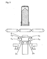
- This stage is shown in Fig. 3 .
- This mold space is shaped such that the concave and convex shape formed by the squeeze feet 15, 15 corresponds to the concave and convex shape of the pattern plate 5. While the extending operation of the first lifting rod 9b is started, the pattern carrier 6 is held by the second lifting member 9g via the operation of the pattern-carrier holding means 9h, 9h.
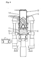
- the molding sand S is blow-filled by low-pressure air from the sand-filling nozzles 16, 16 into the mold space, as shown in Fig. 4 .
- the air for blow-filling at the low pressure is discharged from the aforementioned vent holes (not shown) formed in the filling frame and/or vent holes (not shown) of the pattern plate 5.
- the upwardly-facing cylinders 2, 2 are then further retracted to lower the lifting and supporting frame 3 and the elements supported by it, while the filling-frame cylinders 18, 18 are retracted, to perform a primary squeeze of the molding sand until the bottoms of all the squeeze feet are at the same level (during the squeeze the hydraulic fluid for the squeeze feet is allowed to be discharged), while the sliding gate 10 is reversely operated to open the sand-feeding port 11, as shown in Fig. 5 .
- the second lifting rod 9f of the second cylinder 9e is then extended to allow the pattern carrier 6 to slidably move upward via the second lifting member 9g and with the aid of the guide rods 7, 7, to lift the pattern plate 5, to perform a secondary squeeze. Accordingly, the level of the periphery of the surface of the pattern plate 5 comes to coincide with the level of the mating surfaces of the flask 19 (its bottom) and the box-like frame 8 (its top), as shown in Fig. 6 .
- the second lifting rod 9f of the second cylinder 9e is then retracted to lower the pattern plate 5 via the second lifting member 9g, the pattern-carrier holding means 9h, 9h and the pattern carrier 6, to perform a demolding, as shown in Fig. 7 .
- the demolding is carried out with the flask 19 being sandwiched between the filling frame 17 and the box-like frame 8.
- the upwardly-facing cylinders 2, 2 are then extended to lift the sand hopper 14, the squeeze feet 15, 15, and the filling frame 17, while the first cylinder 9a is retracted to lower the pattern carrier 6 and the box-like frame 8, to allow the tight-flask mold M to be free to be transferred, as shown in Fig. 8 .
- an amount of molding sand S is refilled in the sand hopper 14.
- the pattern-carrier holding means 9h, 9h are deactivated, so that the holding of the pattern carrier 6 by the second lifting member 9g, via the pattern-carrier holding means 9h, 9h, is released.
- the tight-flask mold M is then transferred by the roller conveyor 20, and an empty flask is transferred in, while the pattern changer 4 is rotated through 180 degrees to change the pattern plate 5 and the pattern plate 5A. Further, the squeeze feet 15, 15 are moved to form a concave and convex shape corresponding to the concave and convex shape of the pattern plate 5A. The operation explained above may be repeated.
- a mold space is defined by the sand hopper 14, the squeeze means 15, 15, the filling frame 17, the flask 19, pattern plate 5, and the box-like frame 8.
- the mold space (a space in which molding sand is filled) is defined by substantially one step.
- the mold-producing cycle can be shorter than that when a mold space is conventionally formed, requiring two steps, namely, a step of placing a flask on a leveling frame and a step of placing a filling frame on the flask and lowering the squeeze feet to allow it to advance into the filling frame.
- the contact of the bottom of the filling frame 17 with the top of the flask 19 coincides with the contact of the top of the box-like frame 8 with the bottom of the flask, although some time difference between the lowering operation of the sand hopper 14, the squeeze means 15, 15, and the filling frame 17 and the lifting operation of the pattern carrier 6 and the box-like frame 3 may be allowed.
- the tight-flask mold M can be freely transferred.
- the tight-flask mold can be freely transferred by substantially one step.
- the mold-producing cycle can again be shorter than when a mold is conventionally free to be transferred, requiring two steps, namely, a step of allowing the roller device to come into contact with the flask and a step of lifting the flask to the upper stop end.
- the disengagement of the bottom of the filling frame from the top of the flask coincides with the disengagement of the top of the box-like frame 8 from the bottom of the flask, although some difference of time between the lifting operation of the sand hopper 14, the squeeze means 15, 15, and the filling frame 17 and the lowering operation of the pattern carrier 6 and the box-like frame 8 may be allowed.
- the two-stage lifting means 9 for lifting the pattern carrier 6 and the box-like frame 8 is disposed below the pattern carrier 6, which is located above the central part of the base 1 of the molding device, the aforementioned secondary squeeze is easily carried out even in the structure of the present invention, where the flask 19 is not moved vertically.
- the two-stage lifting means 9 includes the first cylinder 9a having the first lifting rod 9b, the tip of which is connected to the first lifting member 9c, and includes the second cylinder 9e having the second lifting rod 9f, wherein the tip of the second lifting rod 9f is connected to the second lifting member 9g, and the second lifting rod 9f is disposed within the first lifting rod 9b of the first cylinder 9a.
- the lifting means 9 can be a compact structure.
- the flask 19 is sandwiched between the filling frame 17 and the box-like frame 8, with the flask 19 being in contact with rollers 20a, 20a of the roller conveyor 20, as in Fig. 3 .
- the molding device of the invention is not limited to this structure.
- the molding device may be provided with a flask-leveling mechanism (not shown). By using this flask-leveling mechanism the flask may be located above the rollers 20a, 20a by a small distance, for example, 5 mm, while being sandwiched between the filling frame 17 and the box-like frame 8.
Landscapes
- Engineering & Computer Science (AREA)
- Mechanical Engineering (AREA)
- Casting Devices For Molds (AREA)
Abstract
Description
- This invention relates to a method and a device for producing a tight-flask mold, especially one for successively producing a plurality of tight-flask molds.
- A
PCT application that was published as International Publication WO0132333 WO132333 - Forming a mold space (a space in which molding sand is filled) in the molding device disclosed in
WO13233 - This invention has been conceived in view of the above circumstances. The purpose of it is to provide a method and a device that can shorten as much as possible the cycle to produce a mold.
- To the above end, the method of the invention is a method for producing a tight-flask mold by transferring the mold to a position between a pattern carrier and a sand hopper by a flask conveyor that horizontally transfers flasks at a transfer level. The method includes the steps of keeping the flask in the position at the transfer level, while lowering the sand hopper, squeeze means, and a filling frame to the flask and lifting the pattern carrier and a box-like frame to the frame, thereby defining a mold space by the sand hopper, the squeeze means, the filling frame, the flask, the pattern carrier, and the box-like frame; squeezing molding sand in the mold space to produce a tight-flask mold; and lifting the sand hopper, the squeeze means, and the filling frame and lowering the pattern carrier and the box-like frame, thereby allowing the tight-flask mold to be ready to be transferred.
- Further, to the above end, the device of the invention is a molding device for producing a tight-flask mold, comprising a lifting and supporting frame mounted on tops of upwardly-facing cylinders that are uprightly mounted on right and left sides of the base of the molding device; a pattern carrier for holding a pattern plate; a box-like frame for surrounding the periphery of the pattern carrier, said box-like frame being vertically movable; a pattern changer rotatably mounted on one of the upwardly-facing cylinders, for holding a plurality of said pattern carriers and for alternatively transferring the pattern carriers to and away from a position above a central part of the base of the molding device; a two-stage lifting means disposed below the pattern carrier that is located above the central part of the base of the molding device, for lifting the pattern carrier and the box-like frame; a sand hopper suspended from the lifting and supporting frame, said sand hopper including an air-ejecting chamber for an aeration that allows air to be ejected into molding sand to fluidize the molding sand; squeeze means mounted on the bottom of the sand hopper; sand-filling nozzles disposed around the squeeze means; a vertically movable filling frame for surrounding the group of the squeeze means and the sand-filling nozzles; and a flask conveyor disposed between the pattern carrier located above the base of the molding device and the sand hopper, for horizontally transferring flasks at a transfer level.
- Clearly, from the above structure of the invention, since in the invention the mold space is formed by substantially one step, namely, by lowering the sand hopper, the squeeze means, and the filling frame, and by lifting the pattern carrier and the box-like frame to the flask, the cycle to produce a mold is shorter than in the conventional two-step mold space forming. Further, since after demolding the tight-flask mold is made ready to be transferred by substantially one step, namely, by lifting the sand hopper, the squeeze means, and the filling frame, and by lowering the pattern carrier and the box-like frame, the cycle to produce a mold is again shortened compared with the conventional method, wherein the tight-flask mold is made ready to be transferred by the two steps.
Other embodiments and advantages of the invention will be apparent by reviewing the following embodiments described below in reference to the accompanying drawings. -
-
Figure 1 is a vertical cross-sectional view of the molding device of the embodiment of the present invention, showing the starting state of the operation of the molding device. -
Figure 2 is a view taken in the direction of arrows A inFigure 1 . -
Figure 3 is a vertical cross-sectional view of the molding device ofFigure 1 , showing a defined mold space. -
Figure 4 is a vertical cross-sectional view of the molding device ofFigure 1 , showing the filling of molding sand by aerating. -
Figure 5 is a vertical cross-sectional view of the molding device ofFigure 1 , showing the primary squeeze of the molding sand. -
Figure 6 is a vertical cross-sectional view of the molding device ofFigure 1 , showing the secondary squeeze of the molding sand. -
Figure 7 is a vertical cross-sectional view of the molding device ofFigure 1 , showing the demolding. -
Figure 8 is a vertical cross-sectional view of the molding device ofFigure 1 , showing that the tight-flask mold is ready to be transferred. - The embodiment of the present invention will be explained below in detail. In
Fig. 1 , upwardly-facingcylinders base 1 of a molding device. A lifting and supportingframe 3 is mounted on the tops of thepiston rods cylinders rotary pattern changer 4, which is rotatable in a horizontal plane, is mounted at its central part on one of the upwardly-facingcylinders 2, 2 (the cylinder located at the left side inFig. 1 ) at its lower part.Pattern carriers pattern changer 4. Thepattern carriers pattern carriers base 1 of the molding device. - Further, a plurality of
guide rods pattern carrier guide rods like frames 8, 8A, which surround thepattern carriers Fig. 2 ) are secured to the upper surfaces offrame parts pattern changer 4. The box-like frames 8, 8A are placed in position on thepattern changer 4 by allowing depressions formed in the box-like frames 8, 8A to be placed on and engaged by the positioning members 4b, 4b. Thus thepattern carriers pattern changer 4 through the box-like frames 8, 8A. By this arrangement, the box-like frames 8, 8A are moved upward with respect to theframe parts - To lift the box-
like frame 8, andpattern carrier 6, which is located above the central part of thebase 1 of the molding device, a two-stage lifting means 9 is disposed below thatpattern carrier 6. The structure of the two-stage lifting means (a telescopic cylinder) 9 is now explained in detail. Afirst lifting member 9c, of which the periphery extends upward, is secured to the upper end of afirst lifting rod 9b of afirst cylinder 9a of the two-stage lifting means 9. A throughhole 9d is formed in the center of thefirst lifting members 9c. Further, the two-stage lifting means is arranged such that asecond lifting rod 9f of asecond cylinder 9e is disposed in thefirst lifting rod 9b. Namely, thefirst lifting rod 9b of thefirst cylinder 9a acts as a cylinder of thesecond cylinder 9e. Thesecond lifting rod 9f passes through the throughhole 9d. Further, asecond lifting member 9g is secured to the upper end of thesecond lifting rod 9f. Thesecond lifting member 9g has holdingmeans Fig. 2 ). The pattern-carrier holding means 9h, 9h in this embodiment are means that use electromagnets for holding the pattern carrier. However, those means are not limited to this. There may be other means such as suction or some mechanical members to hold the pattern carrier. - Further, a
sand hopper 14 is suspended from the lifting and supportingframe 3. Thesand hopper 14 has a sand-feeding port 11 at its top, which is opened or closed by asliding gate 10, and has an air-supply pipe 12 at its lower part. By opening a valve (not shown) for the air-supply pipe 12, a low-pressure airflow (for example, at a pressure of 0.05-0.18 MPa) may be introduced into thesand hopper 14 through the air-supply pipe 12. Thesand hopper 14 also has a number of air-ejectingchambers sand hopper 14 for aerating molding sand S in the hopper to fluidize it. Further, a plurality of squeeze feet as a squeeze means are disposed at the lower end of thesand hopper 14. The squeeze feet are vertically movable and can stop at any level along their vertical passage. Sand-fillingnozzles squeeze feet - Further, a filling
frame 17 is disposed and connected to downwardly-facing, filling-frame cylinders nozzles filling frame 17. Further, a roller conveyor 20, acting as a flask conveyor, is disposed in a position between thesand hopper 14 and thepattern carrier 6 that is located above the central part of thebase 1 of the molding device for horizontally transferringflasks 19 to and from that position. The roller conveyor 20, which is secured to a frame (not shown), holds theflasks 19 at the transfer level of the roller conveyor 20, at which level theflasks 19 are transferred along the roller conveyor. - The operation of the molding device arranged as explained above will now be explained in detail.
Fig. 1 shows the stage of a device wherein thepattern carrier 6 in which thepattern plate 5 is placed has been transferred to the position above the central part of thebase 1 of the molding device, and wherein anempty flask 1 has been transferred by the roller conveyor 20 to the position between thesand hopper 14 and thepattern carrier 6. The molding sand S has been introduced into thesand hopper 14, and the plurality ofsqueeze feet pattern plate 5. Further, the box-like frame 8 is located to project upward by a small amount (30 mm in this embodiment) from the periphery of the surface of thepattern plate 5. - From this stage, the sliding
gate 10 is operated to close the sand-feedingport 11. Then, the upwardly-facingcylinders sand hopper 14, thesqueeze feet frame 17 to theflask 19, while thefirst lifting rod 9b is extended from thefirst cylinder 9a to lift thepattern carrier 6 and the box-like frame 8 to theflask 19, to define a mold space by thesand hopper 14, thesqueeze feet frame 17, theflask 19, thepattern plate 5, and the box-like frame 8. This stage is shown inFig. 3 . This mold space is shaped such that the concave and convex shape formed by thesqueeze feet pattern plate 5. While the extending operation of thefirst lifting rod 9b is started, thepattern carrier 6 is held by thesecond lifting member 9g via the operation of the pattern-carrier holding means 9h, 9h. - Next, by ejecting low-pressure airflows from a number of the air-ejecting
chambers sand hopper 14 to aerate and fluidize the molding sand S in thesand hopper 14, and by opening the valve (not shown) of the air-supply pipe 12 to introduce a low-pressure airflow from above to the molding sand S in thesand hopper 14, the molding sand S is blow-filled by low-pressure air from the sand-fillingnozzles Fig. 4 . During this blow-filling, the air for blow-filling at the low pressure is discharged from the aforementioned vent holes (not shown) formed in the filling frame and/or vent holes (not shown) of thepattern plate 5. - The upwardly-facing
cylinders frame 3 and the elements supported by it, while the filling-frame cylinders gate 10 is reversely operated to open the sand-feedingport 11, as shown inFig. 5 . - The
second lifting rod 9f of thesecond cylinder 9e is then extended to allow thepattern carrier 6 to slidably move upward via thesecond lifting member 9g and with the aid of theguide rods pattern plate 5, to perform a secondary squeeze. Accordingly, the level of the periphery of the surface of thepattern plate 5 comes to coincide with the level of the mating surfaces of the flask 19 (its bottom) and the box-like frame 8 (its top), as shown inFig. 6 . - The
second lifting rod 9f of thesecond cylinder 9e is then retracted to lower thepattern plate 5 via thesecond lifting member 9g, the pattern-carrier holding means 9h, 9h and thepattern carrier 6, to perform a demolding, as shown inFig. 7 . The demolding is carried out with theflask 19 being sandwiched between the fillingframe 17 and the box-like frame 8. - The upwardly-facing
cylinders sand hopper 14, thesqueeze feet frame 17, while thefirst cylinder 9a is retracted to lower thepattern carrier 6 and the box-like frame 8, to allow the tight-flask mold M to be free to be transferred, as shown inFig. 8 . During this process an amount of molding sand S is refilled in thesand hopper 14. When the retracting operation of thefirst cylinder 9a terminates, the pattern-carrier holding means 9h, 9h are deactivated, so that the holding of thepattern carrier 6 by thesecond lifting member 9g, via the pattern-carrier holding means 9h, 9h, is released. - The tight-flask mold M is then transferred by the roller conveyor 20, and an empty flask is transferred in, while the
pattern changer 4 is rotated through 180 degrees to change thepattern plate 5 and thepattern plate 5A. Further, thesqueeze feet pattern plate 5A. The operation explained above may be repeated. - In the present invention, by lowering the
sand hopper 14, the squeeze means 15, 15, and the fillingframe 17, to theflask 19, and by lifting thepattern carrier 6 and the box-like frame 8 to the flask, a mold space is defined by thesand hopper 14, the squeeze means 15, 15, the fillingframe 17, theflask 19,pattern plate 5, and the box-like frame 8. By this, the mold space (a space in which molding sand is filled) is defined by substantially one step. Thus the mold-producing cycle can be shorter than that when a mold space is conventionally formed, requiring two steps, namely, a step of placing a flask on a leveling frame and a step of placing a filling frame on the flask and lowering the squeeze feet to allow it to advance into the filling frame. Preferably, the contact of the bottom of the fillingframe 17 with the top of theflask 19 coincides with the contact of the top of the box-like frame 8 with the bottom of the flask, although some time difference between the lowering operation of thesand hopper 14, the squeeze means 15, 15, and the fillingframe 17 and the lifting operation of thepattern carrier 6 and the box-like frame 3 may be allowed. - Further, in the present invention, by lifting the
sand hopper 14, thesqueeze feet frame 17, and by lowering thepattern carrier 6 and the box-like frame 8, the tight-flask mold M can be freely transferred. By this, the tight-flask mold can be freely transferred by substantially one step. Thus the mold-producing cycle can again be shorter than when a mold is conventionally free to be transferred, requiring two steps, namely, a step of allowing the roller device to come into contact with the flask and a step of lifting the flask to the upper stop end. Preferably, the disengagement of the bottom of the filling frame from the top of the flask coincides with the disengagement of the top of the box-like frame 8 from the bottom of the flask, although some difference of time between the lifting operation of thesand hopper 14, the squeeze means 15, 15, and the fillingframe 17 and the lowering operation of thepattern carrier 6 and the box-like frame 8 may be allowed. - Further, since in the present invention the two-stage lifting means 9 for lifting the
pattern carrier 6 and the box-like frame 8 is disposed below thepattern carrier 6, which is located above the central part of thebase 1 of the molding device, the aforementioned secondary squeeze is easily carried out even in the structure of the present invention, where theflask 19 is not moved vertically. Further, the two-stage lifting means 9 includes thefirst cylinder 9a having thefirst lifting rod 9b, the tip of which is connected to thefirst lifting member 9c, and includes thesecond cylinder 9e having thesecond lifting rod 9f, wherein the tip of thesecond lifting rod 9f is connected to thesecond lifting member 9g, and thesecond lifting rod 9f is disposed within thefirst lifting rod 9b of thefirst cylinder 9a. Thus the lifting means 9 can be a compact structure. - In the embodiment of the present invention the
flask 19 is sandwiched between the fillingframe 17 and the box-like frame 8, with theflask 19 being in contact withrollers Fig. 3 . However, the molding device of the invention is not limited to this structure. For example, the molding device may be provided with a flask-leveling mechanism (not shown). By using this flask-leveling mechanism the flask may be located above therollers frame 17 and the box-like frame 8.
Claims (4)
- A method for producing a tight-flask mold by transferring a flask to a position between a pattern carrier and a sand hopper by a flask conveyor that transfers flasks horizontally at a transfer level, comprising the steps of:keeping the flask in the position substantially at the transfer level, while lowering the sand hopper, squeeze means, and a filling frame to the flask and lifting the pattern carrier and a box-like frame to the flask, thereby defining a mold space by the sand hopper, the squeeze means, the filling frame, the flask, the pattern carrier, and the box-like frame;filling molding sand into the mold space;squeezing the molding sand in the mold space to produce a tight-flask mold; andlifting the sand hopper, the squeeze means, and the filling frame and lowering the pattern carrier and the box-like frame, thereby allowing the tight-flask mold to be ready to be transferred.
- A method for producing a tight-flask mold, comprising the steps of:transferring a pattern carrier that holds a pattern plate to a position above a central part of a machine base of a molding device and transferring a flask to a position between the pattern carrier and a sand hopper;lowering the sand hopper, squeeze means, and a filling frame to the flask and lifting the pattern carrier and a box-like frame to the flask, thereby defining a mold space by the sand hopper, the squeeze means, the filling frame, the flask, the pattern carrier, and the box-like frame;filling molding sand from the sand hopper into the mold space through sand-filling nozzles, while aerating the molding sand fed into the sand hopper by ejecting air into the molding sand, to fluidize the molding sand:primarily squeezing the molding sand by the squeeze means;secondarily squeezing the molding sand by moving the pattern plate upward;demolding by lowering the pattern plate; andlifting the sand hopper, the squeeze means, and the filling frame and lowering the pattern carrier and the box-like frame, thereby allowing the tight-flask mold to be ready to be transferred.
- A molding device for producing a tight-flask mold, comprising:a lifting and supporting frame mounted on top of upwardly-facing cylinders that are uprightly mounted on right and left sides of a base of the molding device;a pattern carrier for holding a pattern plate;a box-like frame for surrounding the periphery of the pattern carrier, said box-like frame being vertically movable;a pattern changer rotatably mounted on one of the upwardly-facing cylinders, for holding a plurality of said pattern carriers and for alternatively transferring the pattern carriers to and from a position above a central part of the base of the molding device;a two-stage lifting means disposed below the pattern carrier that is located above the central part of the base of the molding device, for lifting the pattern carrier and the box-like frame;a sand hopper suspended from the lifting and supporting frame, said sand hopper including an air-ejecting chamber for an aeration that allows air to be ejected into molding sand to fluidize the molding sand;squeeze means mounted on the bottom of the sand hopper;sand-filling nozzles disposed around the squeeze means;a vertically movable filling frame for surrounding the group of the squeeze means and the sand-filling nozzles; anda flask conveyor disposed between the pattern carrier located above the base of the molding device and the sand hopper, for horizontally transferring flasks at a transfer level.
- The molding device as set forth in claim 3, wherein the two-stage lifting means includes a first cylinder having a first lifting rod to which a first lifting member is connected and a second cylinder having a second lifting rod to which a second lifting member is connected, said second cylinder being arranged so that the second lifting rod is disposed in the first lifting rod of the first cylinder.
Applications Claiming Priority (1)
| Application Number | Priority Date | Filing Date | Title |
|---|---|---|---|
| JP2007037239 | 2007-02-17 |
Publications (1)
| Publication Number | Publication Date |
|---|---|
| EP1964626A1 true EP1964626A1 (en) | 2008-09-03 |
Family
ID=38461934
Family Applications (1)
| Application Number | Title | Priority Date | Filing Date |
|---|---|---|---|
| EP07012211A Withdrawn EP1964626A1 (en) | 2007-02-17 | 2007-06-21 | Method and device for producing tight-flask molds |
Country Status (3)
| Country | Link |
|---|---|
| EP (1) | EP1964626A1 (en) |
| JP (1) | JP2010519040A (en) |
| WO (1) | WO2008099521A1 (en) |
Families Citing this family (2)
| Publication number | Priority date | Publication date | Assignee | Title |
|---|---|---|---|---|
| JP5455161B2 (en) * | 2010-05-13 | 2014-03-26 | 新東工業株式会社 | Sand cutter device and mold making device |
| JP5626639B2 (en) * | 2010-08-09 | 2014-11-19 | 新東工業株式会社 | Mold making method |
Citations (15)
| Publication number | Priority date | Publication date | Assignee | Title |
|---|---|---|---|---|
| EP0195864A2 (en) * | 1985-03-29 | 1986-10-01 | Osborn Manufacturing Company | Foundry molding machine and method |
| US4860817A (en) * | 1988-01-14 | 1989-08-29 | Georg Fischer Ag | Apparatus for the compacting of granular molding materials |
| EP0900606A1 (en) * | 1997-09-05 | 1999-03-10 | Sintokogio, Ltd. | Apparatus for making mold |
| EP0995521A1 (en) * | 1998-10-19 | 2000-04-26 | Josef Mertes | Foundry moulding machine |
| WO2001032333A1 (en) * | 1999-11-04 | 2001-05-10 | Sintokogio, Ltd. | Molding device and molding method or sand mold |
| EP1184106A1 (en) * | 2000-02-17 | 2002-03-06 | Sintokogio, Ltd. | Method and device for filling casting sand |
| EP1208928A1 (en) * | 2000-04-21 | 2002-05-29 | Sintokogio, Ltd. | Die molding machine and pattern carrier |
| EP1222979A1 (en) * | 2000-04-13 | 2002-07-17 | Sintokogio, Ltd. | Compressing method for casting sand and device therefor |
| EP1240957A2 (en) * | 2001-03-16 | 2002-09-18 | Sintokogio, Ltd. | Method and apparatus for compacting molding sand |
| JP2002346698A (en) * | 2001-05-29 | 2002-12-03 | Sintokogio Ltd | Method and apparatus for filling molding sand in a frameless horizontal split mold making machine |
| EP1433548A1 (en) * | 2001-08-06 | 2004-06-30 | Sintokogio, Ltd. | Method and system for monitoring molding machine |
| JP2005007439A (en) * | 2003-06-19 | 2005-01-13 | Sintokogio Ltd | Mold making method |
| JP2005329469A (en) * | 2005-08-19 | 2005-12-02 | Sintokogio Ltd | Pattern carrier transfer mechanism |
| JP2005334976A (en) * | 2005-08-29 | 2005-12-08 | Sintokogio Ltd | Mold making method and apparatus |
| EP1738847A1 (en) * | 2004-04-21 | 2007-01-03 | Sintokogio, Ltd. | Method for manufacturing sandmold |
-
2007
- 2007-06-21 EP EP07012211A patent/EP1964626A1/en not_active Withdrawn
- 2007-06-29 JP JP2009521467A patent/JP2010519040A/en active Pending
- 2007-06-29 WO PCT/JP2007/063517 patent/WO2008099521A1/en not_active Ceased
Patent Citations (16)
| Publication number | Priority date | Publication date | Assignee | Title |
|---|---|---|---|---|
| EP0195864A2 (en) * | 1985-03-29 | 1986-10-01 | Osborn Manufacturing Company | Foundry molding machine and method |
| US4860817A (en) * | 1988-01-14 | 1989-08-29 | Georg Fischer Ag | Apparatus for the compacting of granular molding materials |
| EP0900606A1 (en) * | 1997-09-05 | 1999-03-10 | Sintokogio, Ltd. | Apparatus for making mold |
| EP0995521A1 (en) * | 1998-10-19 | 2000-04-26 | Josef Mertes | Foundry moulding machine |
| WO2001032333A1 (en) * | 1999-11-04 | 2001-05-10 | Sintokogio, Ltd. | Molding device and molding method or sand mold |
| EP1149646A1 (en) * | 1999-11-04 | 2001-10-31 | Sintokogio, Ltd. | Molding device and molding method or sand mold |
| EP1184106A1 (en) * | 2000-02-17 | 2002-03-06 | Sintokogio, Ltd. | Method and device for filling casting sand |
| EP1222979A1 (en) * | 2000-04-13 | 2002-07-17 | Sintokogio, Ltd. | Compressing method for casting sand and device therefor |
| EP1208928A1 (en) * | 2000-04-21 | 2002-05-29 | Sintokogio, Ltd. | Die molding machine and pattern carrier |
| EP1240957A2 (en) * | 2001-03-16 | 2002-09-18 | Sintokogio, Ltd. | Method and apparatus for compacting molding sand |
| JP2002346698A (en) * | 2001-05-29 | 2002-12-03 | Sintokogio Ltd | Method and apparatus for filling molding sand in a frameless horizontal split mold making machine |
| EP1433548A1 (en) * | 2001-08-06 | 2004-06-30 | Sintokogio, Ltd. | Method and system for monitoring molding machine |
| JP2005007439A (en) * | 2003-06-19 | 2005-01-13 | Sintokogio Ltd | Mold making method |
| EP1738847A1 (en) * | 2004-04-21 | 2007-01-03 | Sintokogio, Ltd. | Method for manufacturing sandmold |
| JP2005329469A (en) * | 2005-08-19 | 2005-12-02 | Sintokogio Ltd | Pattern carrier transfer mechanism |
| JP2005334976A (en) * | 2005-08-29 | 2005-12-08 | Sintokogio Ltd | Mold making method and apparatus |
Non-Patent Citations (1)
| Title |
|---|
| "RECENT TRENDS IN GREENSAND MOULDING MACHINE DESIGN", FOUNDRY TRADE JOURNAL, INSTITUTE OF CAST METALS ENGINEERS, WEST BROMWICH, GB, vol. 166, no. 3453, 1 May 1992 (1992-05-01), pages 254,256,258,26, XP000267328, ISSN: 0015-9042 * |
Also Published As
| Publication number | Publication date |
|---|---|
| WO2008099521A1 (en) | 2008-08-21 |
| JP2010519040A (en) | 2010-06-03 |
Similar Documents
| Publication | Publication Date | Title |
|---|---|---|
| KR100721633B1 (en) | Molding machine for producing the death penalty and the method of manufacturing the death penalty | |
| TW555600B (en) | Die molding machine and pattern carrier | |
| CN108367341B (en) | Mold molding machine, sand filling compression unit, and mold molding method | |
| US6684933B2 (en) | Method and apparatus for compacting molding sand | |
| US7726380B2 (en) | Method for manufacturing sand mold | |
| KR100778162B1 (en) | Compression method of foundry sand and its device | |
| US7654302B2 (en) | Method and apparatus for molding an upper and a lower mold having no flask, and a method for replacing a match plate used therefor | |
| CN108290209B (en) | Die Molding Machine | |
| WO2008099521A1 (en) | Method and device for producing tight-flask molds | |
| JP2002336936A (en) | Sand molding device with frame, pattern carrier, pattern exchange device, pattern carrier setting device, and molding method of sand mold with frame | |
| JP6665935B2 (en) | Mold making method | |
| JP4352364B2 (en) | Molding equipment for sand mold with frame | |
| JP4292582B2 (en) | Mold making method | |
| JP2001353557A (en) | Method and apparatus for forming sand mold with frame | |
| JP3441065B2 (en) | Mold molding method and molding apparatus | |
| JP2001321889A (en) | Molding apparatus and pattern carrier for sand mold with frame | |
| JP2001300691A (en) | Method and apparatus for forming sand mold with frame |
Legal Events
| Date | Code | Title | Description |
|---|---|---|---|
| PUAI | Public reference made under article 153(3) epc to a published international application that has entered the european phase |
Free format text: ORIGINAL CODE: 0009012 |
|
| 17P | Request for examination filed |
Effective date: 20071221 |
|
| AK | Designated contracting states |
Kind code of ref document: A1 Designated state(s): AT BE BG CH CY CZ DE DK EE ES FI FR GB GR HU IE IS IT LI LT LU LV MC MT NL PL PT RO SE SI SK TR |
|
| AX | Request for extension of the european patent |
Extension state: AL BA HR MK RS |
|
| AKX | Designation fees paid |
Designated state(s): AT BE BG CH CY CZ DE DK EE ES FI FR GB GR HU IE IS IT LI LT LU LV MC MT NL PL PT RO SE SI SK TR |
|
| STAA | Information on the status of an ep patent application or granted ep patent |
Free format text: STATUS: THE APPLICATION HAS BEEN WITHDRAWN |
|
| 18W | Application withdrawn |
Effective date: 20090508 |