EP1963894B1 - Piezoelektrische fluid-linse mit variablem fokus und fokussierungsverfahren - Google Patents
Piezoelektrische fluid-linse mit variablem fokus und fokussierungsverfahren Download PDFInfo
- Publication number
- EP1963894B1 EP1963894B1 EP06842517A EP06842517A EP1963894B1 EP 1963894 B1 EP1963894 B1 EP 1963894B1 EP 06842517 A EP06842517 A EP 06842517A EP 06842517 A EP06842517 A EP 06842517A EP 1963894 B1 EP1963894 B1 EP 1963894B1
- Authority
- EP
- European Patent Office
- Prior art keywords
- meniscus
- fluid
- focus lens
- piezoelectric element
- variable focus
- Prior art date
- Legal status (The legal status is an assumption and is not a legal conclusion. Google has not performed a legal analysis and makes no representation as to the accuracy of the status listed.)
- Active
Links
- 239000012530 fluid Substances 0.000 title claims abstract description 147
- 238000000034 method Methods 0.000 title claims description 8
- 230000005499 meniscus Effects 0.000 claims abstract description 98
- 230000003287 optical effect Effects 0.000 claims abstract description 56
- 238000013519 translation Methods 0.000 claims abstract description 4
- 230000008859 change Effects 0.000 claims description 29
- 150000001875 compounds Chemical class 0.000 claims description 6
- 230000005855 radiation Effects 0.000 claims description 4
- 239000000463 material Substances 0.000 description 14
- 239000010410 layer Substances 0.000 description 10
- 230000005611 electricity Effects 0.000 description 7
- 239000011248 coating agent Substances 0.000 description 5
- 238000000576 coating method Methods 0.000 description 5
- 230000008901 benefit Effects 0.000 description 4
- 238000010586 diagram Methods 0.000 description 4
- 230000001939 inductive effect Effects 0.000 description 4
- 239000007788 liquid Substances 0.000 description 4
- 229920000089 Cyclic olefin copolymer Polymers 0.000 description 3
- 239000004713 Cyclic olefin copolymer Substances 0.000 description 3
- 230000004913 activation Effects 0.000 description 3
- 238000004519 manufacturing process Methods 0.000 description 3
- 230000004044 response Effects 0.000 description 3
- 238000009736 wetting Methods 0.000 description 3
- 230000004075 alteration Effects 0.000 description 2
- 230000001419 dependent effect Effects 0.000 description 2
- 239000002355 dual-layer Substances 0.000 description 2
- 238000012986 modification Methods 0.000 description 2
- 230000004048 modification Effects 0.000 description 2
- 239000004033 plastic Substances 0.000 description 2
- 239000011241 protective layer Substances 0.000 description 2
- LKAPTZKZHMOIRE-KVTDHHQDSA-N (2s,3s,4s,5r)-3,4-dihydroxy-5-(hydroxymethyl)oxolane-2-carbaldehyde Chemical compound OC[C@H]1O[C@H](C=O)[C@@H](O)[C@@H]1O LKAPTZKZHMOIRE-KVTDHHQDSA-N 0.000 description 1
- KTTCLOUATPWTNB-UHFFFAOYSA-N 2-[2-[4-(6,7-dimethoxy-3,4-dihydro-1h-isoquinolin-2-yl)butylcarbamoyl]-4-methylphenoxy]ethyl methanesulfonate Chemical compound C1C=2C=C(OC)C(OC)=CC=2CCN1CCCCNC(=O)C1=CC(C)=CC=C1OCCOS(C)(=O)=O KTTCLOUATPWTNB-UHFFFAOYSA-N 0.000 description 1
- 101100243959 Drosophila melanogaster Piezo gene Proteins 0.000 description 1
- 238000013459 approach Methods 0.000 description 1
- LKAPTZKZHMOIRE-UHFFFAOYSA-N chitose Natural products OCC1OC(C=O)C(O)C1O LKAPTZKZHMOIRE-UHFFFAOYSA-N 0.000 description 1
- 238000004891 communication Methods 0.000 description 1
- 238000010276 construction Methods 0.000 description 1
- 210000002858 crystal cell Anatomy 0.000 description 1
- 230000000694 effects Effects 0.000 description 1
- 239000013013 elastic material Substances 0.000 description 1
- 238000011156 evaluation Methods 0.000 description 1
- 230000004313 glare Effects 0.000 description 1
- 238000005286 illumination Methods 0.000 description 1
- 239000004973 liquid crystal related substance Substances 0.000 description 1
- 230000007246 mechanism Effects 0.000 description 1
- 239000012528 membrane Substances 0.000 description 1
- ORQBXQOJMQIAOY-UHFFFAOYSA-N nobelium Chemical compound [No] ORQBXQOJMQIAOY-UHFFFAOYSA-N 0.000 description 1
- 229920000515 polycarbonate Polymers 0.000 description 1
- 239000004417 polycarbonate Substances 0.000 description 1
- 238000012545 processing Methods 0.000 description 1
Images


Classifications
-
- G—PHYSICS
- G02—OPTICS
- G02B—OPTICAL ELEMENTS, SYSTEMS OR APPARATUS
- G02B3/00—Simple or compound lenses
- G02B3/12—Fluid-filled or evacuated lenses
- G02B3/14—Fluid-filled or evacuated lenses of variable focal length
-
- G—PHYSICS
- G02—OPTICS
- G02B—OPTICAL ELEMENTS, SYSTEMS OR APPARATUS
- G02B26/00—Optical devices or arrangements for the control of light using movable or deformable optical elements
- G02B26/004—Optical devices or arrangements for the control of light using movable or deformable optical elements based on a displacement or a deformation of a fluid
- G02B26/005—Optical devices or arrangements for the control of light using movable or deformable optical elements based on a displacement or a deformation of a fluid based on electrowetting
-
- G—PHYSICS
- G02—OPTICS
- G02B—OPTICAL ELEMENTS, SYSTEMS OR APPARATUS
- G02B3/00—Simple or compound lenses
Definitions
- the present disclosures relate generally to variable focus lenses, and more particularly, to a piezoelectric variable focus lens and a method of making the same.
- fluid focus lenses There exist a number of technical implementations of a fluid focus, for example, as discussed in WO 03/069380 and WO 2004/102253 , assigned to the assignee of the present disclosure.
- the principle of fluid focus lenses is based on sandwiching of two liquids, one of them conductive and the other non-conductive, between transparent panes, attaching contacts, and controlling a shape of the interface between the two liquids through voltage, using electro-wetting principles.
- electro-wetting principles are not very well understood and are difficult to utilize. Accordingly, conventional fluid focus lenses have a number of challenges, for example, with respect to choice of materials, particularly the fluids used, and proper functioning under various temperature conditions.
- the shape of the meniscus between the two fluids is altered, not using electro-wetting principles, but rather by changing the relative volume of each of the fluids using a pump.
- pump systems may be technically complicated and difficult to control.
- a fluid focus lens includes a chamber with an optical axis extending through the chamber.
- a cylindrical element made from piezoelectric material is provided on a portion of the inside of the chamber, and attached at one side of the end of the chamber.
- the chamber further includes a first fluid and a second fluid in contact via a meniscus extending transverse the optical axis.
- the perimeter of the meniscus is fixedly located on one side of the internal surface of the cylindrical element, for example, using a suitable coating that attracts the first fluid and repels the second fluid, or vice versa.
- the piezoelectric material is connected to a source of electricity, or voltage potential. Changes in the source of electricity, or voltage potential, induce a change in the length of the piezoelectric material, and move the perimeter of the meniscus, thus inducing a change of the shape of the meniscus. Additional designs are also disclosed.
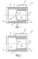
- a piezoelectric fluid focus lens 10 includes a fluid chamber 12 having side walls 14 and transparent end plates 16 and 18. Fluid chamber 12 further includes an optical axis 20 generally disposed along a length dimension of the sidewalls and extending through the chamber.
- a cylindrical element made from piezoelectric material 22 is provided on the inside of the chamber 12, extending partway through the chamber 12. In addition, the piezoelectric material attaches on one side, on the end plate 18 of the chamber 12.
- the chamber 12 further comprises a first fluid 24 and a second, non-miscible, fluid 26 in contact via a meniscus 28.
- the meniscus 28 extends transverse the optical axis 20.
- the perimeter 30 of the meniscus 28 is fixedly located on one side of the cylindrical piezoelectric element 22.
- the piezoelectric element 22 couples to a source of electricity, via suitable connections, as indicated by reference numeral 32. As shown in Figure 1 , the source of electricity, or voltage potential, is at V 1 .
- Changes in this source 32 for example, from voltage V 1 to voltage V 2 , induce a change in the length 34 of the piezoelectric element 22, and move the perimeter of the meniscus, thus inducing a change of the shape of the meniscus, such as indicated by the phantom line 36 in Figure 1 .
- a variable focus lens 10 comprises a fluid chamber 12 having an optical axis 20, a piezoelectric element 22 circumferentially disposed about the optical axis 20 within a portion of the fluid chamber12.
- First and second fluids are disposed within another portion the fluid chamber 12 and in contact with one another via a meniscus 28 extending transverse the optical axis 20.
- the perimeter 30 of the meniscus 28 is fixedly located on a surface of the piezoelectric element 22.
- the first and second fluids are substantially immiscible and have different indices of refraction.
- the first fluid comprises an insulating fluid and the second fluid comprises a conducting fluid.
- the first fluid comprises a vapor and the second fluid comprises a conducting fluid.
- FIG. 1 is a cross-section view of the fluid focus lens of Figure 1 showing the meniscus having a second shape according to an embodiment of the present disclosure.
- Figure 2 illustrates the shape of the meniscus 36 in response to application of voltage potential 32 at voltage V 2 .
- the fluid chamber 12 comprises a substantially cylindrical chamber having a cylinder wall 14, a front element 16, and a rear element 18.
- the front element 16 includes a transparent portion and the rear element 18 includes a transparent portion.
- the transparent portion can comprise the entire front element or the entire rear element.
- the piezoelectric element 22 can further comprise a front surface and a rear surface.
- the perimeter of the meniscus 30 is fixedly located on the front surface of the piezoelectric element 22.
- the back surface of the piezoelectric element 22 is fixedly attached to the rear element 18 of the fluid chamber 12. Furthermore, application of a voltage potential to the piezoelectric element induces a change in length of the piezoelectric element 22 in a direction parallel to the optical axis 20.
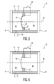
- FIG 3 is a schematic cross-section view of a piezoelectric fluid focus lens 40 according to another embodiment of the present disclosure.
- Fluid focus lens 40 includes a fluid chamber 42 having side walls 44 and transparent end plates 46 and 48.
- Fluid chamber 42 further includes an optical axis 50 generally disposed along a length dimension of the sidewalls and extending through the chamber.
- a cylindrical element 52 made from piezoelectric material is provided on the inside of the chamber 12.
- the piezoelectric element 52 further comprises an inner ring 54.
- First and second fluids, indicated by reference numerals 56 and 58, respectively, are disposed within the fluid chamber 42 and in contact with one another via a meniscus 60 extending transverse the optical axis 50.
- the perimeter of the meniscus 60 is fixedly located on the inner ring 54, for example, as indicated by reference numeral 62.
- the piezoelectric element 52 is fixedly coupled to an inner surface 45 of the fluid chamber 42.
- application of a voltage potential 32 to the piezoelectric element 52 induces a change in dimension of the piezoelectric element such that the inner ring 54 traverses in a direction substantially parallel to the optical axis.
- the source of electricity is at a first voltage V 1 .
- Changes in the source 32 from the first voltage V 1 to a second voltage V 2 induces a change in dimension of the piezoelectric element 52, moves the perimeter of the meniscus, and thus induces a change of the shape of the meniscus, such as indicated by the phantom line 64 in Figure 3 .
- FIG. 4 is a cross-section view of the fluid focus lens of Figure 3 showing the meniscus having a second shape according to an embodiment of the present disclosure.
- Figure 4 illustrates the shape of the meniscus 64 in response to application of voltage potential 32 at voltage V 2 .
- the piezoelectric element 52 is levered in such a way as to enhance the changes on the meniscus 60.
- typical changes in piezoelectric elements are very small.
- one such piezoelectric element may exhibit a stroke in the order of twelve ⁇ m (12 ⁇ m) for a length of thirty-one mm (31 mm).
- Figures 3 and 4 show one possible such construction.
- Piezoelectric element 52 is clamped between and fixed to sidewalls 44. Inducing a shape change will induce a leveraged expansion from a first state 60 to a second state 64.
- a circular hole or ring 54 cut into the middle of the piezoelectric element would hold the meniscus.
- the meniscus would also change from a first state 60 to a second state 64.
- Other similar ways to use a leverage mechanism to enhance the piezo-induced physical change of the position of a ring holding the meniscus are also possible.
- the piezoelectric element 52 can further comprise an inner circumferential surface and an outer surface.
- the perimeter 62 of the meniscus 60 is fixedly located on the inner circumferential surface.
- the outer circumferential surface of the piezoelectric element 52 is fixedly coupled to an inner surface 45 of the chamber 42.
- the inner circumferential surface includes a front, middle, and a rear surface of the piezoelectric element 52.
- the perimeter of the meniscus 62 is fixedly located on one of the front, middle, or rear surface of the piezoelectric element 52, for example, using a suitable coating that attracts the first fluid and repels the second fluid, or vice versa.
- the outer surface of the piezoelectric element may comprise a circumferential outer surface.
- Fluid focus lens 70 includes a fluid chamber 72 having side walls 74 and transparent end plates 76 and 78. Fluid chamber 72 further includes an optical axis 80 generally disposed along a length dimension of the sidewalls and extending through the chamber. A cylindrical element made from piezoelectric material 82 is provided on the inside of the chamber 72. First and second fluids, indicated by reference numerals 84 and 86, respectively, are disposed within the fluid chamber 72 and in contact with one another via a meniscus 88 extending transverse the optical axis 80.
- the meniscus is attached to a wall section of piezoelectric element 82 of the fluid lens 70, for example, by a coating 90 that attracts the first fluid 84 and repels the second fluid 86.
- a coating could include a hydrophilic coating, for example.
- the wall section of piezoelectric element 82 is designed in such a way that its diameter can be changed orthogonally to the optical axis 80 of the fluid lens 70.
- the wall section is made of a piezoelectric material. The change of the wall section from a first position to a second position results in the shape of the meniscus changing from a first shape 88 into a second shape 92.
- a voltage potential 32 to the piezoelectric element 82 induces a change in dimension of the piezoelectric element in a direction substantially transverse or orthogonal to the optical axis 80.
- the source of electricity is at a first voltage V 1 .
- Changes in the source 32 from the first voltage V 1 to a second voltage V 2 induces a change in dimension of the piezoelectric element 80, moves the perimeter of the meniscus, and thus induces a change of the shape of the meniscus, such as indicated by the phantom line 92 in Figure 5 .
- Figure 6 is a cross-section view of the fluid focus lens of Figure 5 showing the meniscus having a second shape according to an embodiment of the present disclosure.
- Figure 6 illustrates the shape of the meniscus 92 in response to application of voltage potential 32 at voltage V 2 .
- the drawing figures are not necessarily drawn to scale; however, they are illustrative of the principals of the embodiments of the present disclosure.
- the illustrations in Figures 5 and 6 are intended to show that the fluid volumes on each side of the meniscus are basically the same.
- the fluid focus lens could further include a suitable means configured for accommodating miniscule volume changes induced by the piezoelectric element(s).
- a suitable means configured for accommodating miniscule volume changes induced by the piezoelectric element(s).
- a small volume of gas (as indicated, for example, by phantom lines and reference numeral 85 in Figures 5 and 6 ) could be introduced in communication with the fluid chamber and in a location away from (or distal) the optical path, wherein the small volume of gas provides compensation for the volume changes induced by the piezoelectric element(s).
- the gas is non-miscible with the fluid in which the gas contacts for providing the desired compensation.
- Yet another embodiment includes providing one or more portion(s) of the fluid chamber walls with elastic material (forming an elastic portion or portions), wherein the elastic portion provides compensation for miniscule volume changes induced by the piezoelectric element(s).
- the sidewalls are generally cylindrical, although some variation from a perfect cylinder is possible, e.g. slightly conical.
- the cylinder should generally remain substantially cylindrical, namely where the fluid contact layer has a linear cross section, i.e. the layer forms straight lines in a cross section of the cylinder, where the axis of the cylinder lies in the cross section.
- the linear cross section should be parallel to the axis of the electrode at least to within ten (10) degrees, and more preferably at least to within one (1) degree.
- the cylindrical sidewalls can be made using suitable tubing having a cross section which is parallel to the axis, for example, within one-tenth (0.1) degree and a smooth inner wall on which the various layers can be attached. The possibility of using such tubing provides the fluid focus lens according to the embodiments of the present disclosure with a cost advantage.
- the sidewalls are formed in a shape other than cylindrical.
- the sidewalls can be formed of a rectangular shape as shown in Figures 7 and 8 .
- the piezoelectric element may comprise one or more piezoelectric elements.
- various attributes of the embodiments as discussed herein with respect to the embodiments of Figures 1-6 can also be applied to the embodiments of Figures 7 and 8 , as appropriate, for a given fluid focus lens application.
- fluid focus lens 200 includes a fluid chamber 202 having side walls 204 and transparent end plates 206 and 208.
- Fluid chamber 202 further includes an optical axis 210 generally disposed along a length dimension of the sidewalls and extending through the chamber.
- One or more elements 212-1, 212-2 made from piezoelectric material are provided on the inside of the chamber 202.
- First and second fluids, indicated by reference numerals 214 and 216, respectively, are disposed within the fluid chamber 202 and in contact with one another via a meniscus 218 extending transverse the optical axis 210.
- the piezoelectric elements 212-1, 212-2 the elements change from a first dimension to a second dimension, wherein the shape of meniscus 218 changes into another shape, as indicated by reference numeral 220.
- fluid focus lens 300 includes a fluid chamber 302 having side walls 304 and transparent end plates 306 and 308.
- Fluid chamber 302 further includes an optical axis 310 generally disposed along a length dimension of the sidewalls and extending through the chamber.
- First and second elements 312-1, 312-2 made from piezoelectric material are provided on the inside of the chamber 302. In this embodiment, the first and second elements 312-1 and 312-2 can be actuated independently, using suitable activation means.
- First and second fluids, indicated by reference numerals 314 and 316, respectively, are disposed within the fluid chamber 302 and in contact with one another via a meniscus 318 extending transverse the optical axis 310.
- the elements respectively change from a first dimension to a second dimension, in a manner wherein the shape of meniscus 318 is substantially maintained, however, meniscus 318 is translated a given amount (such as indicated by translated axis 311) as determined by the change in dimension of elements 312-1, 312-2.
- element 312-1 undergoes an increase in dimension
- element 312-2 undergoes a decrease in dimension (e.g., by a substantially equivalent amount as the increase in dimension of element 312-1).
- the lens could then change shape in a different way, or even be shifted sideways while maintaining the same focal strength, etc.
- FIG 9 is a cross section schematic block diagram view of an image capture device 100 including a piezoelectric fluid focus lens 10 in accordance with an embodiment of the present disclosure. Elements similar to that described in relation to Figures 1 to 8 are provided with the same reference numerals, and the previous description of these similar elements should be taken to apply here.
- the device includes a compound variable focus lens 10 including cylindrical sidewalls 14, a rigid front lens 102 and a rigid rear lens 104.
- the space enclosed by the two lenses and the cylindrical sidewalls 14 form a cylindrical fluid chamber 12.
- the fluid chamber 12 holds the first and second fluids 24 and 26.
- the two fluids touch along a meniscus 36.
- the meniscus forms a meniscus lens of variable power, as previously described, depending on a voltage applied to the piezoelectric element 22.
- the two fluids 24 and 26 have changed position.
- the front lens 102 is a convex-convex lens of highly refracting plastic, such as polycarbonate or cyclic olefin copolymer, and having a positive power.
- the surfaces of the front lens are configured to provide desired initial focusing characteristics.
- the rear lens element 104 is formed of a low dispersive plastic, such as COC (cyclic olefin copolymer) and includes lens surfaces configured to act as a field flattener on one surface, wherein the other surface of the rear lens element may be flat, spherical or aspherical.
- a glare stop 106 and an aperture stop 108 are added to the front of the lens.
- a pixellated image sensor 110 such as a CMOS sensor array, is located in a sensor plane behind the lens.
- An electronic control circuit 112 drives the meniscus lens, in accordance with a focus control signal, derived by focus control processing of the image signals, so as to provide an object range of between infinity and a few centimeters.
- the control circuit controls the applied voltage between a low voltage level, at which focusing on infinity is achieved, and other higher voltage levels, when closer objects are to be focused.
- the lens is configured such that a low, non-zero, voltage is applied to focus the lens on an object at infinity (parallel incoming rays), so as to provide the capability to focus on infinity within reasonable manufacturing tolerances, if on the other hand the lens were to be configured such that focusing on infinity occurred when zero voltage is applied, more strict manufacturing tolerances would have to be applied.
- the front lens element 102 is preferably formed as a single body with a tube 14 holding the piezoelectric element 22 on its inner surface and closed off by the rear lens 104 to form a sealed unit.
- the second lens element 104 may be extended, in relation to that shown in Figure 9 , and the flat rear surface of the lens element 104 may be replaced by an angled mirror surface, preferably angled at 45°, to allow the image sensor 110 to be placed below the lens, in order to reduce the dimensions of the lens.
- the fluid chamber 12 may be provided with an expansion chamber to accommodate volume changes due to thermal expansion of the fluids.
- the expansion chamber may be a flexible membrane in one of the walls of the fluid chamber.
- the inner surfaces of the front lens 102 and the rear lens 104 may be coated with a protective layer to avoid incompatibility of the material from which the lenses are made with the fluids 24 and 26.
- the protective layer may also have anti- reflection characteristics.
- Figure 10 is a cross section schematic block diagram view of an optical scanning device including a piezoelectric fluid focus lens in accordance with another embodiment of the present disclosure.
- Figure 10 shows elements from an optical scanning device containing a lens in accordance with an embodiment of the present disclosures.
- the device is for recording and/or playback from an optical disk 126, for example a dual layer digital video recording (DVR) disk (see for instance the article by K. Schep, B.Stek, R. van Woudenberg, M. Blum, S. Kobayashi, T. Narahara, T. Yamagami, H.Ogawa, "Format description and evaluation of the 22.5 GB DVR disc", Technical Digest, ISOM 2000, Chitose, Japan, Sept. 5-8, 2000 ).
- DVR digital video recording
- the device includes a compound objective lens, for instance having a numerical aperture of 0.85, including a rigid front lens 122 and a rigid rear lens 124, for instance as described in International patent application WO 01/73775 , for focusing the incoming collimated beam, for instance, having a desired wavelength, consisting of substantially parallel rays, to a spot 128 in the plane of an information layer currently being scanned.
- a compound objective lens for instance having a numerical aperture of 0.85, including a rigid front lens 122 and a rigid rear lens 124, for instance as described in International patent application WO 01/73775 , for focusing the incoming collimated beam, for instance, having a desired wavelength, consisting of substantially parallel rays, to a spot 128 in the plane of an information layer currently being scanned.
- the two information layers are at depths of 0.1 mm and 0.08 mm; they are thus separated by typically 0.02 mm.
- a mechanical actuator for example moving a collimator lens in the device, which is relatively expensive.
- a switchable liquid crystal cell which is also a relatively expensive solution.
- a switchable variable focus lens 10 similar to that described in relation to Figures 1 to 8 is used.
- the device includes an electronic control circuit 130 for applying one of two selected voltages to the electrodes of the lens 10 in dependence on the information layer currently being scanned.
- a relatively low selected voltage is applied to produce a first meniscus curvature radius.
- a relatively high selected voltage is applied to produce a planar meniscus curvature.
- the first fluid may consist of a vapor rather than an insulating liquid.
- the second fluid may be a fluid having a lower surface tension than the first fluid. In that case, the shape of the meniscus at low applied voltages will be convex. It is to be understood that any feature described in relation to one embodiment may also be used in other of the embodiments.
- the meniscus responsive to application of a first voltage potential to the piezoelectric element, the meniscus is characterized by a first shape.
- the meniscus responsive to application of a second voltage potential to the piezoelectric element, different from the first voltage potential, the meniscus is characterized by a second shape, different from the first shape.
- the first shape comprises a concave shape when viewed from the second fluid and the second shape comprises a less concave shape.
- the first fluid has a larger refractive index than the second fluid.
- the variable focus lens is a compound lens, further comprising: at least one fixed lens element providing a positive lens power, such that the compound lens has a positive lens power when the meniscus is convex in relation to the first fluid.
- An optical device is also contemplated that comprises a variable focus lens according to the embodiments disclosed herein.
- the optical device further comprises a means for defining a focusing plane with respect to the variable focus lens, wherein responsive to an input of radiation consisting.of parallel rays and a non-zero voltage potential applied to the piezoelectric element, the radiation is focused on the focusing plane.
- the embodiments further contemplate an image capture device comprising a variable focus lens as disclosed and discussed herein.
- the embodiments still further contemplate an optical scanning device for scanning an optical record carrier, comprising a variable focus lens according to the various embodiments disclosed herein.
- a piezoelectric fluid focus lens 150 includes a fluid chamber 12, side walls 14, transparent end plates 16 and 18, and an optical axis 20, similar as discussed herein with respect to the embodiment of Figure 1 .
- One or more element 22 made from piezoelectric material is provided on the inside of the chamber 12, extending partway through the chamber 12.
- the piezoelectric material attaches on one side, i.e., on the end plate 18 of the chamber 12.
- the chamber 12 further comprises a first fluid 24 and a second, non-miscible, fluid 26 in contact via a meniscus 28.
- the meniscus 28 extends transverse the optical axis 20.
- the perimeter 30 of the meniscus 28 is fixedly located on a surface in relationship to one or more of the piezoelectric elements 22.
- the surface comprises a surface of one or more intermediate elements 152.
- the one or more intermediate elements 152 are physically disposed between the one or more piezoelectric elements 22 and the meniscus 28.
- the piezoelectric element 22 couples to a source of electricity (not shown), via suitable connections, as discussed previously with respect to the earlier embodiments.
- Changes in the vo ltage source for example, from voltage V 1 to voltage V 2 , induce a change in the length 34 of the piezoelectric element 22, which impart a force on the one or more intermediate elements 152 and move the perimeter 30 of the meniscus, thus inducing a change of the shape of the meniscus, such as indicated by the 28-1 in Figure 11 .
- the upper half of Figure 11 represents the shape of a portion of the meniscus 28 at voltage V 1
- the lower half of Figure 11 represents the shape of a portion of the meniscus 28-1 at voltage V 2 .
- While only one intermediate element is illustrated in Figure 11 , additional configurations using multiple intermediate elements are possible.
- one or more intermediate elements as illustrated in Figure 11 may also be applied to the embodiments of Figures 1-10 , as may be appropriate for a given optical application.
- a method of operating a variable focus lens including a fluid chamber having an optical axis, one or more piezoelectric element disposed about the optical axis within a portion of the fluid chamber, and first and second fluids disposed within another portion the fluid chamber and in contact with one another via a meniscus extending transverse the optical axis, the perimeter of the meniscus being fixedly located on a surface in relationship to the one or more piezoelectric element, the first and second fluids being substantially immiscible and having different indices of refraction, comprises controlling a voltage potential applied to the one or more piezoelectric element to change one or more of (i) the shape of the meniscus or (ii) a translation of the meniscus.
- Controlling the voltage potential can include varying the voltage potential to produce a meniscus shape that is concave when viewed from the second fluid. Controlling the voltage potential can also include varying the voltage potential to produce a meniscus shape that is convex when viewed from the second fluid.
- the embodiments of the present disclosure can be applied to fluid lens applications such as in camera phones, photo and video cameras, optical pickup devices, medical equipment, identification applications, automotive applications, and lighting applications, such as LED illumination.
- the lens can further be of any optical element shape, including other than cylindrical, as appropriate for the requirements of a given optical application.
- the embodiments of the present disclosure reduce the need for moving optical elements and provide for a number of advantages, for example, one or more of durability, simplicity, speed, and cost.
- any reference signs placed in parentheses in one or more claims shall not be construed as limiting the claims.
- the word “comprising” and “comprises,” and the like, does not exclude the presence of elements or steps other than those listed in any claim or the specification as a whole.
- the singular reference of an element does not exclude the plural references of such elements and vice-versa.
- One or more of the embodiments may be implemented by means of hardware comprising several distinct elements, and/or by means of a suitably programmed computer. In a device claim enumerating several means, several of these means may be embodied by one and the same item of hardware.
- the mere fact that certain measures are recited in mutually different dependent claims does not indicate that a combination of these measures cannot be used to an advantage.
Landscapes
- Physics & Mathematics (AREA)
- General Physics & Mathematics (AREA)
- Optics & Photonics (AREA)
- Mechanical Light Control Or Optical Switches (AREA)
- Lenses (AREA)
- Lens Barrels (AREA)
- Optical Head (AREA)
- Automatic Focus Adjustment (AREA)
Claims (23)
- Linse (10) mit variablem Fokus, mit:einer Fluidkammer (12) mit einer optischen Achse (20);einem oder mehreren piezoelektrischen Elementen (22), die um die optische Achse innerhalb eines Teils der Fluidkammer angeordnet sind; sowieeinem ersten und einem zweiten Fluid (24,26), die innerhalb eines anderes Teils der Fluidkammer angeordnet und über einen sich quer zu der optischen Achse erstreckenden Meniskus (28,36) in Kontakt miteinander sind, wobei der Perimeter des Meniskus fest auf einer Oberfläche vorgesehen ist, wobei die Oberfläche eine oder mehrere Oberflächen (i) einer Oberfläche des einen oder der mehreren piezoelektrischen Elemente (22,52,82,212,312) oder (ii) einer Oberfläche eines oder mehrerer Zwischenelemente (152) aufweist, wobei das eine oder die mehreren Zwischenelemente zwischen dem einen oder den mehreren piezoelektrischen Elementen und dem Meniskus (28) physikalisch angeordnet sind, wobei das erste und zweite Fluid im Wesentlichen nicht mischbar sind und unterschiedliche Brechungsindizes aufweisen, wobei, in Reaktion auf das Anlegen eines oder mehrerer Spannungspotentiale an das eine oder die mehreren piezoelektrischen Elemente, das eine oder die mehreren piezoelektrischen Elemente eine oder mehrere (i) Formen des Meniskus oder (ii) eine Translation des Meniskus steuerbar verändern.
- Linse (10) mit variablem Fokus nach Anspruch 1, wobei das erste Fluid (24) ein isolierendes Fluid und das zweite Fluid (26) ein leitendes Fluid umfasst.
- Linse mit variablem Fokus nach Anspruch 1, wobei das erste Fluid (24) einen Dampf und das zweite Fluid (26) ein leitendes Fluid umfasst.
- Linse mit variablem Fokus nach Anspruch 1, wobei die Fluidkammer (12) eine im Wesentlichen zylindrische Kammer mit einer zylindrischen Wand (14), ein vorderes Element (16) und ein rückwärtiges Element (18) umfasst.
- Linse mit variablem Fokus nach Anspruch 4, wobei weiterhin das vordere Element (16) einen transparenten Teil enthält, und wobei das rückwärtige Element (18) einen transparenten Teil enthält.
- Linse mit variablem Fokus nach Anspruch 5, wobei das piezoelektrische Element (22) weiterhin eine vordere Fläche (34) und eine rückwärtige Fläche umfasst, wobei weiterhin der Perimeter des Meniskus auf der vorderen Fläche fest angeordnet ist, und wobei die rückwärtige Fläche der piezoelektrischen Oberfläche an dem rückwärtigen Element (18) fest angebracht ist.
- Linse mit variablem Fokus nach Anspruch 6, wobei das Anlegen des Spannungspotentials (32) an das piezoelektrische Element eine Änderung der Länge des piezoelektrischen Elements in einer Richtung parallel zu der optischen Achse induziert.
- Linse mit variablem Fokus nach Anspruch 1, wobei das piezoelektrische Element (52) weiterhin einen inneren Ring (54) umfasst, wobei weiterhin der Perimeter (62) des Meniskus (60,64) auf dem inneren Ring fest angeordnet ist, und wobei das piezoelektrische Element an eine Innenfläche (45) der Kammer fest gekoppelt ist.
- Linse mit variablem Fokus nach Anspruch 8, wobei das Anlegen des Spannungspotentials (32) an das piezoelektrische Element eine Änderung der Dimension des piezoelektrischen Elements dahingehend induziert, dass sich der innere Ring in einer Richtung im Wesentlichen parallel zu der optischen Achse verschiebt.
- Linse mit variablem Fokus nach Anspruch 1, wobei das piezoelektrische Element (82) weiterhin eine innere Umfangsfläche (90) und eine äußere Umfangsfläche umfasst, wobei weiterhin der Perimeter des Meniskus (88,92) auf der inneren Umfangsfläche fest angeordnet und die äußere Umfangsfläche des piezoelektrischen Elements an eine Innenfläche der Kammer (74) fest gekoppelt ist.
- Linse mit variablem Fokus nach Anspruch 10, wobei weiterhin die innere Umfangsfläche eine vordere, eine mittlere und eine rückwärtige Fläche des piezoelektrischen Elements enthält, und wobei der Perimeter des Meniskus auf der vorderen, mittleren oder rückwärtigen Fläche des piezoelektrischen Elements fest angeordnet ist.
- Linse mit variablem Fokus nach Anspruch 10, wobei weiterhin das Anlegen des Spannungspotentials (32) an das piezoelektrische Element eine Änderung der Dimension des piezoelektrischen Elements in einer radialen Richtung, quer zu der optischen Achse, induziert.
- Linse mit variablem Fokus nach Anspruch 1, wobei das piezoelektrische Element (82) weiterhin eine Innenfläche und eine Außenfläche umfasst, wobei die Innenfläche eine vordere, eine mittlere und eine rückwärtige Fläche enthält, wobei weiterhin der Perimeter des Meniskus auf der vorderen, mittleren oder rückwärtigen Fläche der Innenfläche fest angeordnet ist, und wobei die Außenfläche der piezoelektrischen Oberfläche an eine Innenfläche der Kammer fest gekoppelt ist.
- Linse mit variablem Fokus nach Anspruch 13, wobei weiterhin das Anlegen des Spannungspotentials (32) an das piezoelektrische Element eine Änderung der Dimension des piezoelektrischen Elements in einer radialen Richtung, quer zu der optischen Achse, induziert.
- Linse mit variablem Fokus nach Anspruch 1, wobei, in Reaktion auf das Anlegen eines ersten Spannungspotentials an das piezoelektrische Element, der Meniskus durch eine erste Form gekennzeichnet ist, und wobei weiterhin, in Reaktion auf das Anlegen eines zweiten, von dem ersten Spannungspotential abweichenden Spannungspotentials an das piezoelektrische Element, der Meniskus durch eine zweite, von der ersten Form abweichende Form gekennzeichnet ist.
- Linse mit variablem Fokus nach Anspruch 15, wobei die erste Form, wenn von dem zweiten Fluid aus betrachtet, eine konkave Form und die zweite Form eine weniger konkave Form umfasst.
- Linse mit variablem Fokus nach Anspruch 1, wobei das erste Fluid (24) einen größeren Brechungsindex als das zweite Fluid (26) aufweist, und wobei die Linse mit variablem Fokus eine zusammengesetzte Linse, welche weiterhin umfasst:mindestens ein festes Linsenelement, welches eine positive Linsenleistung vorsieht, so dass die zusammengesetzte Linse eine positive Linsenleistung aufweist, wenn der Meniskus in Relation zu dem ersten Fluid konvex ist.
- Optische Einrichtung mit einer Linse (10) mit variablem Fokus nach Anspruch 1, wobei die optische Einrichtung weiterhin umfasst:Mittel, um eine Fokussierebene gegenüber der Linse mit variablem Fokus zu definieren, wobei, in Reaktion auf einen Strahlungseingang, der aus parallelen Strahlen und einer an das piezoelektrische Element angelegten Spannung ungleich Null besteht, die Strahlung auf die Fokussierebene fokussiert wird.
- Bilderfassungseinrichtung (100) mit einer Linse mit variablem Fokus nach Anspruch 1.
- Optische Abtasteinrichtung (120) zum Abtasten eines optischen Aufzeichnungsträgers mit einer Linse mit variablem Fokus nach Anspruch 1.
- Verfahren zum Betreiben einer Linse (10) mit variablem Fokus, welche eine Fluidkammer (12) mit einer optischen Achse (20), eine oder mehrere piezoelektrische Elemente (22), welche um die optische Achse innerhalb eines Teils der Fluidkammer angeordnet sind, sowie ein erstes und zweites Fluid (24,26) enthält, die innerhalb eines anderes Teils der Fluidkammer angeordnet und über einen sich quer zu der optischen Achse erstreckenden Meniskus (28,36) in Kontakt miteinander sind, wobei der Perimeter des Meniskus fest auf einer Oberfläche vorgesehen ist, wobei die Oberfläche eine oder mehrere (i) einer Oberfläche des einen oder der mehreren piezoelektrischen Elemente oder (ii) einer Oberfläche eines oder mehrerer Zwischenelemente aufweist, wobei das eine oder die mehreren Zwischenelemente zwischen dem einen oder den mehreren piezoelektrischen Elementen und dem Meniskus physikalisch angeordnet sind, wobei das erste und zweite Fluid im Wesentlichen nicht mischbar sind und unterschiedliche Brechungsindizes aufweisen, wobei das Verfahren umfasst:Steuerung eines Spannungspotentials (32), welches an das eine oder mehrere piezoelektrische Elemente angelegt wird, um eine oder mehrere (i) Formen des Meniskus oder (ii) eine Translation des Meniskus zu verändern.
- Verfahren nach Anspruch 21, wobei die Steuerung des Spannungspotentials das Variieren des Spannungspotentials umfasst, um eine Meniskusform zu erzeugen, welche, wenn von dem zweiten Fluid aus betrachtet, konkav ist.
- Verfahren nach Anspruch 21, wobei die Steuerung des Spannungspotentials das Variieren des Spannungspotentials umfasst, um eine Meniskusform zu erzeugen, welche, wenn von dem zweiten Fluid aus betrachtet, konvex ist.
Applications Claiming Priority (2)
| Application Number | Priority Date | Filing Date | Title |
|---|---|---|---|
| US75142405P | 2005-12-16 | 2005-12-16 | |
| PCT/IB2006/054846 WO2007069213A2 (en) | 2005-12-16 | 2006-12-14 | Piezoelectric variable focus fluid lens and method of focusing |
Publications (2)
| Publication Number | Publication Date |
|---|---|
| EP1963894A2 EP1963894A2 (de) | 2008-09-03 |
| EP1963894B1 true EP1963894B1 (de) | 2009-07-08 |
Family
ID=38066617
Family Applications (1)
| Application Number | Title | Priority Date | Filing Date |
|---|---|---|---|
| EP06842517A Active EP1963894B1 (de) | 2005-12-16 | 2006-12-14 | Piezoelektrische fluid-linse mit variablem fokus und fokussierungsverfahren |
Country Status (9)
| Country | Link |
|---|---|
| US (1) | US20080316610A1 (de) |
| EP (1) | EP1963894B1 (de) |
| JP (1) | JP2009519498A (de) |
| KR (1) | KR20080076946A (de) |
| CN (1) | CN101331413A (de) |
| AT (1) | ATE436035T1 (de) |
| DE (1) | DE602006007735D1 (de) |
| TW (1) | TW200730881A (de) |
| WO (1) | WO2007069213A2 (de) |
Families Citing this family (34)
| Publication number | Priority date | Publication date | Assignee | Title |
|---|---|---|---|---|
| DE102005039561A1 (de) * | 2005-08-22 | 2007-03-01 | Robert Bosch Gmbh | Temperaturkompensation optischer Systeme |
| CN101501534A (zh) * | 2006-08-15 | 2009-08-05 | 皇家飞利浦电子股份有限公司 | 可变焦透镜 |
| US7755841B2 (en) * | 2007-01-30 | 2010-07-13 | Dmetrix, Inc. | Liquid-lens variable-control optics in array microscope |
| JP5419005B2 (ja) * | 2008-02-15 | 2014-02-19 | 国立大学法人 東京大学 | 可変焦点レンズ |
| US8699141B2 (en) * | 2009-03-13 | 2014-04-15 | Knowles Electronics, Llc | Lens assembly apparatus and method |
| US8659835B2 (en) | 2009-03-13 | 2014-02-25 | Optotune Ag | Lens systems and method |
| US8282004B2 (en) * | 2009-04-29 | 2012-10-09 | Hand Held Products, Inc. | Focusing apparatus and terminal comprising variable focus lens assembly |
| WO2010129454A1 (en) * | 2009-05-03 | 2010-11-11 | Lensvector, Inc. | Optical lens having fixed lenses and embedded active optics |
| EP2443626A2 (de) * | 2009-06-19 | 2012-04-25 | Koninklijke Philips Electronics N.V. | Bildgebungssystem zur abbildung eines viskoelastischen mediums |
| JP5743399B2 (ja) * | 2009-12-21 | 2015-07-01 | キヤノン株式会社 | 液体レンズ |
| JP5590901B2 (ja) * | 2010-02-03 | 2014-09-17 | キヤノン株式会社 | 屈折力可変素子 |
| DE102010001551A1 (de) * | 2010-02-03 | 2011-08-04 | TRUMPF Laser- und Systemtechnik GmbH, 71254 | Adaptive Linse |
| JP5382944B2 (ja) * | 2010-03-12 | 2014-01-08 | 富士フイルム株式会社 | 可変焦点レンズ及びその液体充填方法 |
| WO2012010201A1 (en) | 2010-07-20 | 2012-01-26 | Fraunhofer-Gesellschaft zur Förderung der angewandten Forschung e.V. | Fluidic variable focal length optical lens and method for manufacturing the same |
| US8506105B2 (en) * | 2010-08-25 | 2013-08-13 | Generla Electric Company | Thermal management systems for solid state lighting and other electronic systems |
| CN101950078B (zh) * | 2010-09-07 | 2012-03-28 | 华中科技大学 | 基于逆压电效应的可变焦双液体透镜 |
| US8780449B2 (en) * | 2010-11-23 | 2014-07-15 | National Taipei University Of Technology | Method for compensating aberration of variable focus liquid lens |
| US9442285B2 (en) | 2011-01-14 | 2016-09-13 | The Board Of Trustees Of The University Of Illinois | Optical component array having adjustable curvature |
| WO2012158709A1 (en) | 2011-05-16 | 2012-11-22 | The Board Of Trustees Of The University Of Illinois | Thermally managed led arrays assembled by printing |
| US12517342B2 (en) | 2011-06-21 | 2026-01-06 | Gholam A. Peyman | Fluidic phoropter system |
| US12216266B2 (en) * | 2011-06-21 | 2025-02-04 | Gholam A. Peyman | Fluidic glasses for correcting refractive errors of a human or animal |
| KR102177133B1 (ko) | 2014-01-31 | 2020-11-10 | 매직 립, 인코포레이티드 | 멀티-포컬 디스플레이 시스템 및 방법 |
| CN106233189B (zh) | 2014-01-31 | 2020-06-26 | 奇跃公司 | 多焦点显示系统和方法 |
| DE102014205790A1 (de) * | 2014-03-27 | 2015-10-01 | Albert-Ludwigs-Universität Freiburg | Optofluidisches Bauelement |
| NZ727361A (en) | 2014-05-30 | 2020-05-29 | Magic Leap Inc | Methods and systems for displaying stereoscopy with a freeform optical system with addressable focus for virtual and augmented reality |
| CN112987307B (zh) * | 2014-05-30 | 2022-06-28 | 奇跃公司 | 用于在虚拟和增强现实中产生焦平面的方法和系统 |
| JP2018106127A (ja) * | 2016-12-28 | 2018-07-05 | 株式会社ミツトヨ | レンズシステムおよび焦点距離可変レンズ装置 |
| US10677967B1 (en) * | 2018-01-22 | 2020-06-09 | Facebook Technologies, Llc | Flexible border allowing vertical translation of membrane for fluid-filled lens |
| US10677966B1 (en) * | 2018-01-22 | 2020-06-09 | Facebook Technologies, Llc | Flexible border allowing hinge rotation of membrane for fluid-filled lens |
| KR102521613B1 (ko) * | 2018-05-04 | 2023-04-13 | 엘지이노텍 주식회사 | 액체 렌즈 제어 회로, 카메라 모듈 및 액체 렌즈 제어 방법 |
| KR102777670B1 (ko) * | 2019-07-09 | 2025-03-11 | 엘지이노텍 주식회사 | 액체 렌즈 제어 장치 및 그의 제어 방법 |
| KR102925262B1 (ko) * | 2020-06-25 | 2026-02-09 | 엘지이노텍 주식회사 | 가변초점 렌즈모듈 및 이를 갖는 라이트 필드 카메라 |
| CN115542438A (zh) * | 2022-10-31 | 2022-12-30 | 业泓科技(成都)有限公司 | 液体式变焦镜头装置 |
| CN221465835U (zh) * | 2023-12-12 | 2024-08-02 | 比亚迪股份有限公司 | 一种光学元件、透镜、光学系统及电子设备 |
Family Cites Families (4)
| Publication number | Priority date | Publication date | Assignee | Title |
|---|---|---|---|---|
| GB1327503A (en) * | 1971-02-05 | 1973-08-22 | Bosch Gmbh Robert | Optical lenses |
| NL8501101A (nl) * | 1985-04-15 | 1986-04-01 | Optische Ind De Oude Delft Nv | Optisch element met een variabele brandpuntsafstand. |
| GB0407414D0 (en) * | 2004-04-01 | 2004-05-05 | 1 Ltd | Variable focal length lens |
| US7221514B2 (en) * | 2005-04-15 | 2007-05-22 | Asml Netherlands B.V. | Variable lens and exposure system |
-
2006
- 2006-12-13 TW TW095146685A patent/TW200730881A/zh unknown
- 2006-12-14 AT AT06842517T patent/ATE436035T1/de not_active IP Right Cessation
- 2006-12-14 KR KR1020087014371A patent/KR20080076946A/ko not_active Ceased
- 2006-12-14 CN CNA2006800474590A patent/CN101331413A/zh active Pending
- 2006-12-14 WO PCT/IB2006/054846 patent/WO2007069213A2/en not_active Ceased
- 2006-12-14 US US12/097,607 patent/US20080316610A1/en not_active Abandoned
- 2006-12-14 DE DE602006007735T patent/DE602006007735D1/de not_active Expired - Fee Related
- 2006-12-14 EP EP06842517A patent/EP1963894B1/de active Active
- 2006-12-14 JP JP2008545232A patent/JP2009519498A/ja active Pending
Also Published As
| Publication number | Publication date |
|---|---|
| TW200730881A (en) | 2007-08-16 |
| US20080316610A1 (en) | 2008-12-25 |
| JP2009519498A (ja) | 2009-05-14 |
| WO2007069213A2 (en) | 2007-06-21 |
| CN101331413A (zh) | 2008-12-24 |
| WO2007069213A3 (en) | 2007-10-11 |
| KR20080076946A (ko) | 2008-08-20 |
| EP1963894A2 (de) | 2008-09-03 |
| DE602006007735D1 (de) | 2009-08-20 |
| ATE436035T1 (de) | 2009-07-15 |
Similar Documents
| Publication | Publication Date | Title |
|---|---|---|
| EP1963894B1 (de) | Piezoelektrische fluid-linse mit variablem fokus und fokussierungsverfahren | |
| EP1478951B1 (de) | Linse mit variablem fokus | |
| Hendriks et al. | Electrowetting-based variable-focus lens for miniature systems | |
| EP1625442B1 (de) | Linse mit variabler form | |
| EP1625441B1 (de) | Variable linse | |
| EP1706761B1 (de) | Elektrobenetzungseinrichtung | |
| TWI291036B (en) | Switchable optical element | |
| CN1754112A (zh) | 包括由两种不可混溶流体的界面形成的可变透镜的用于光盘记录/再现装置的物镜 | |
| US20090046195A1 (en) | Varible focus lens | |
| JP2007519973A (ja) | 可変レンズ系 | |
| CN100465670C (zh) | 可变透镜 | |
| CN100570718C (zh) | 光学扫描装置 | |
| EP1875278B1 (de) | Linse mit variablem fokus |
Legal Events
| Date | Code | Title | Description |
|---|---|---|---|
| PUAI | Public reference made under article 153(3) epc to a published international application that has entered the european phase |
Free format text: ORIGINAL CODE: 0009012 |
|
| 17P | Request for examination filed |
Effective date: 20080716 |
|
| AK | Designated contracting states |
Kind code of ref document: A2 Designated state(s): AT BE BG CH CY CZ DE DK EE ES FI FR GB GR HU IE IS IT LI LT LU LV MC NL PL PT RO SE SI SK TR |
|
| GRAP | Despatch of communication of intention to grant a patent |
Free format text: ORIGINAL CODE: EPIDOSNIGR1 |
|
| GRAS | Grant fee paid |
Free format text: ORIGINAL CODE: EPIDOSNIGR3 |
|
| GRAA | (expected) grant |
Free format text: ORIGINAL CODE: 0009210 |
|
| AK | Designated contracting states |
Kind code of ref document: B1 Designated state(s): AT BE BG CH CY CZ DE DK EE ES FI FR GB GR HU IE IS IT LI LT LU LV MC NL PL PT RO SE SI SK TR |
|
| REG | Reference to a national code |
Ref country code: GB Ref legal event code: FG4D |
|
| REG | Reference to a national code |
Ref country code: CH Ref legal event code: EP |
|
| REG | Reference to a national code |
Ref country code: IE Ref legal event code: FG4D |
|
| REF | Corresponds to: |
Ref document number: 602006007735 Country of ref document: DE Date of ref document: 20090820 Kind code of ref document: P |
|
| PG25 | Lapsed in a contracting state [announced via postgrant information from national office to epo] |
Ref country code: SI Free format text: LAPSE BECAUSE OF FAILURE TO SUBMIT A TRANSLATION OF THE DESCRIPTION OR TO PAY THE FEE WITHIN THE PRESCRIBED TIME-LIMIT Effective date: 20090708 |
|
| NLV1 | Nl: lapsed or annulled due to failure to fulfill the requirements of art. 29p and 29m of the patents act | ||
| PG25 | Lapsed in a contracting state [announced via postgrant information from national office to epo] |
Ref country code: AT Free format text: LAPSE BECAUSE OF FAILURE TO SUBMIT A TRANSLATION OF THE DESCRIPTION OR TO PAY THE FEE WITHIN THE PRESCRIBED TIME-LIMIT Effective date: 20090708 Ref country code: IS Free format text: LAPSE BECAUSE OF FAILURE TO SUBMIT A TRANSLATION OF THE DESCRIPTION OR TO PAY THE FEE WITHIN THE PRESCRIBED TIME-LIMIT Effective date: 20091108 Ref country code: ES Free format text: LAPSE BECAUSE OF FAILURE TO SUBMIT A TRANSLATION OF THE DESCRIPTION OR TO PAY THE FEE WITHIN THE PRESCRIBED TIME-LIMIT Effective date: 20091019 Ref country code: LT Free format text: LAPSE BECAUSE OF FAILURE TO SUBMIT A TRANSLATION OF THE DESCRIPTION OR TO PAY THE FEE WITHIN THE PRESCRIBED TIME-LIMIT Effective date: 20090708 Ref country code: FI Free format text: LAPSE BECAUSE OF FAILURE TO SUBMIT A TRANSLATION OF THE DESCRIPTION OR TO PAY THE FEE WITHIN THE PRESCRIBED TIME-LIMIT Effective date: 20090708 |
|
| PG25 | Lapsed in a contracting state [announced via postgrant information from national office to epo] |
Ref country code: LV Free format text: LAPSE BECAUSE OF FAILURE TO SUBMIT A TRANSLATION OF THE DESCRIPTION OR TO PAY THE FEE WITHIN THE PRESCRIBED TIME-LIMIT Effective date: 20090708 Ref country code: NL Free format text: LAPSE BECAUSE OF FAILURE TO SUBMIT A TRANSLATION OF THE DESCRIPTION OR TO PAY THE FEE WITHIN THE PRESCRIBED TIME-LIMIT Effective date: 20090708 Ref country code: PL Free format text: LAPSE BECAUSE OF FAILURE TO SUBMIT A TRANSLATION OF THE DESCRIPTION OR TO PAY THE FEE WITHIN THE PRESCRIBED TIME-LIMIT Effective date: 20090708 |
|
| PG25 | Lapsed in a contracting state [announced via postgrant information from national office to epo] |
Ref country code: PT Free format text: LAPSE BECAUSE OF FAILURE TO SUBMIT A TRANSLATION OF THE DESCRIPTION OR TO PAY THE FEE WITHIN THE PRESCRIBED TIME-LIMIT Effective date: 20091109 Ref country code: BG Free format text: LAPSE BECAUSE OF FAILURE TO SUBMIT A TRANSLATION OF THE DESCRIPTION OR TO PAY THE FEE WITHIN THE PRESCRIBED TIME-LIMIT Effective date: 20091008 |
|
| PG25 | Lapsed in a contracting state [announced via postgrant information from national office to epo] |
Ref country code: CZ Free format text: LAPSE BECAUSE OF FAILURE TO SUBMIT A TRANSLATION OF THE DESCRIPTION OR TO PAY THE FEE WITHIN THE PRESCRIBED TIME-LIMIT Effective date: 20090708 Ref country code: EE Free format text: LAPSE BECAUSE OF FAILURE TO SUBMIT A TRANSLATION OF THE DESCRIPTION OR TO PAY THE FEE WITHIN THE PRESCRIBED TIME-LIMIT Effective date: 20090708 Ref country code: RO Free format text: LAPSE BECAUSE OF FAILURE TO SUBMIT A TRANSLATION OF THE DESCRIPTION OR TO PAY THE FEE WITHIN THE PRESCRIBED TIME-LIMIT Effective date: 20090708 Ref country code: DK Free format text: LAPSE BECAUSE OF FAILURE TO SUBMIT A TRANSLATION OF THE DESCRIPTION OR TO PAY THE FEE WITHIN THE PRESCRIBED TIME-LIMIT Effective date: 20090708 |
|
| PLBE | No opposition filed within time limit |
Free format text: ORIGINAL CODE: 0009261 |
|
| STAA | Information on the status of an ep patent application or granted ep patent |
Free format text: STATUS: NO OPPOSITION FILED WITHIN TIME LIMIT |
|
| PG25 | Lapsed in a contracting state [announced via postgrant information from national office to epo] |
Ref country code: SK Free format text: LAPSE BECAUSE OF FAILURE TO SUBMIT A TRANSLATION OF THE DESCRIPTION OR TO PAY THE FEE WITHIN THE PRESCRIBED TIME-LIMIT Effective date: 20090708 Ref country code: BE Free format text: LAPSE BECAUSE OF FAILURE TO SUBMIT A TRANSLATION OF THE DESCRIPTION OR TO PAY THE FEE WITHIN THE PRESCRIBED TIME-LIMIT Effective date: 20090708 |
|
| 26N | No opposition filed |
Effective date: 20100409 |
|
| PG25 | Lapsed in a contracting state [announced via postgrant information from national office to epo] |
Ref country code: MC Free format text: LAPSE BECAUSE OF NON-PAYMENT OF DUE FEES Effective date: 20100701 |
|
| REG | Reference to a national code |
Ref country code: FR Ref legal event code: ST Effective date: 20100831 |
|
| PG25 | Lapsed in a contracting state [announced via postgrant information from national office to epo] |
Ref country code: GR Free format text: LAPSE BECAUSE OF FAILURE TO SUBMIT A TRANSLATION OF THE DESCRIPTION OR TO PAY THE FEE WITHIN THE PRESCRIBED TIME-LIMIT Effective date: 20091009 Ref country code: FR Free format text: LAPSE BECAUSE OF NON-PAYMENT OF DUE FEES Effective date: 20091231 Ref country code: IE Free format text: LAPSE BECAUSE OF NON-PAYMENT OF DUE FEES Effective date: 20091214 |
|
| PG25 | Lapsed in a contracting state [announced via postgrant information from national office to epo] |
Ref country code: DE Free format text: LAPSE BECAUSE OF NON-PAYMENT OF DUE FEES Effective date: 20100701 |
|
| PG25 | Lapsed in a contracting state [announced via postgrant information from national office to epo] |
Ref country code: LU Free format text: LAPSE BECAUSE OF NON-PAYMENT OF DUE FEES Effective date: 20091214 |
|
| PG25 | Lapsed in a contracting state [announced via postgrant information from national office to epo] |
Ref country code: HU Free format text: LAPSE BECAUSE OF FAILURE TO SUBMIT A TRANSLATION OF THE DESCRIPTION OR TO PAY THE FEE WITHIN THE PRESCRIBED TIME-LIMIT Effective date: 20100109 |
|
| REG | Reference to a national code |
Ref country code: CH Ref legal event code: PL |
|
| GBPC | Gb: european patent ceased through non-payment of renewal fee |
Effective date: 20101214 |
|
| PG25 | Lapsed in a contracting state [announced via postgrant information from national office to epo] |
Ref country code: TR Free format text: LAPSE BECAUSE OF FAILURE TO SUBMIT A TRANSLATION OF THE DESCRIPTION OR TO PAY THE FEE WITHIN THE PRESCRIBED TIME-LIMIT Effective date: 20090708 |
|
| PG25 | Lapsed in a contracting state [announced via postgrant information from national office to epo] |
Ref country code: CY Free format text: LAPSE BECAUSE OF FAILURE TO SUBMIT A TRANSLATION OF THE DESCRIPTION OR TO PAY THE FEE WITHIN THE PRESCRIBED TIME-LIMIT Effective date: 20090708 |
|
| PG25 | Lapsed in a contracting state [announced via postgrant information from national office to epo] |
Ref country code: CH Free format text: LAPSE BECAUSE OF NON-PAYMENT OF DUE FEES Effective date: 20101231 Ref country code: LI Free format text: LAPSE BECAUSE OF NON-PAYMENT OF DUE FEES Effective date: 20101231 |
|
| PG25 | Lapsed in a contracting state [announced via postgrant information from national office to epo] |
Ref country code: GB Free format text: LAPSE BECAUSE OF NON-PAYMENT OF DUE FEES Effective date: 20101214 |
|
| PGFP | Annual fee paid to national office [announced via postgrant information from national office to epo] |
Ref country code: IT Payment date: 20091231 Year of fee payment: 4 |
|
| PG25 | Lapsed in a contracting state [announced via postgrant information from national office to epo] |
Ref country code: SE Free format text: LAPSE BECAUSE OF FAILURE TO SUBMIT A TRANSLATION OF THE DESCRIPTION OR TO PAY THE FEE WITHIN THE PRESCRIBED TIME-LIMIT Effective date: 20090708 |