EP1963017B1 - Verfahren und vorrichtung zum entnehmen einer probe aus einer flüssigkeitbasierten zytologischen probe - Google Patents
Verfahren und vorrichtung zum entnehmen einer probe aus einer flüssigkeitbasierten zytologischen probe Download PDFInfo
- Publication number
- EP1963017B1 EP1963017B1 EP06848603A EP06848603A EP1963017B1 EP 1963017 B1 EP1963017 B1 EP 1963017B1 EP 06848603 A EP06848603 A EP 06848603A EP 06848603 A EP06848603 A EP 06848603A EP 1963017 B1 EP1963017 B1 EP 1963017B1
- Authority
- EP
- European Patent Office
- Prior art keywords
- vial
- aliquot
- chamber
- sample
- collection chamber
- Prior art date
- Legal status (The legal status is an assumption and is not a legal conclusion. Google has not performed a legal analysis and makes no representation as to the accuracy of the status listed.)
- Not-in-force
Links
Images


Classifications
-
- B—PERFORMING OPERATIONS; TRANSPORTING
- B01—PHYSICAL OR CHEMICAL PROCESSES OR APPARATUS IN GENERAL
- B01L—CHEMICAL OR PHYSICAL LABORATORY APPARATUS FOR GENERAL USE
- B01L3/00—Containers or dishes for laboratory use, e.g. laboratory glassware; Droppers
- B01L3/02—Burettes; Pipettes
- B01L3/0241—Drop counters; Drop formers
- B01L3/0272—Dropper bottles
-
- B—PERFORMING OPERATIONS; TRANSPORTING
- B01—PHYSICAL OR CHEMICAL PROCESSES OR APPARATUS IN GENERAL
- B01L—CHEMICAL OR PHYSICAL LABORATORY APPARATUS FOR GENERAL USE
- B01L3/00—Containers or dishes for laboratory use, e.g. laboratory glassware; Droppers
- B01L3/50—Containers for the purpose of retaining a material to be analysed, e.g. test tubes
- B01L3/508—Rigid containers without fluid transport within
- B01L3/5082—Test tubes per se
- B01L3/50825—Closing or opening means, corks, bungs
-
- B—PERFORMING OPERATIONS; TRANSPORTING
- B01—PHYSICAL OR CHEMICAL PROCESSES OR APPARATUS IN GENERAL
- B01L—CHEMICAL OR PHYSICAL LABORATORY APPARATUS FOR GENERAL USE
- B01L2300/00—Additional constructional details
- B01L2300/04—Closures and closing means
- B01L2300/046—Function or devices integrated in the closure
- B01L2300/047—Additional chamber, reservoir
-
- B—PERFORMING OPERATIONS; TRANSPORTING
- B01—PHYSICAL OR CHEMICAL PROCESSES OR APPARATUS IN GENERAL
- B01L—CHEMICAL OR PHYSICAL LABORATORY APPARATUS FOR GENERAL USE
- B01L2300/00—Additional constructional details
- B01L2300/04—Closures and closing means
- B01L2300/046—Function or devices integrated in the closure
- B01L2300/049—Valves integrated in closure
-
- B—PERFORMING OPERATIONS; TRANSPORTING
- B01—PHYSICAL OR CHEMICAL PROCESSES OR APPARATUS IN GENERAL
- B01L—CHEMICAL OR PHYSICAL LABORATORY APPARATUS FOR GENERAL USE
- B01L2300/00—Additional constructional details
- B01L2300/08—Geometry, shape and general structure
- B01L2300/0832—Geometry, shape and general structure cylindrical, tube shaped
-
- B—PERFORMING OPERATIONS; TRANSPORTING
- B01—PHYSICAL OR CHEMICAL PROCESSES OR APPARATUS IN GENERAL
- B01L—CHEMICAL OR PHYSICAL LABORATORY APPARATUS FOR GENERAL USE
- B01L2400/00—Moving or stopping fluids
- B01L2400/06—Valves, specific forms thereof
- B01L2400/0633—Valves, specific forms thereof with moving parts
-
- G—PHYSICS
- G01—MEASURING; TESTING
- G01N—INVESTIGATING OR ANALYSING MATERIALS BY DETERMINING THEIR CHEMICAL OR PHYSICAL PROPERTIES
- G01N35/00—Automatic analysis not limited to methods or materials provided for in any single one of groups G01N1/00 - G01N33/00; Handling materials therefor
- G01N2035/00465—Separating and mixing arrangements
- G01N2035/00524—Mixing by agitating sample carrier
-
- G—PHYSICS
- G01—MEASURING; TESTING
- G01N—INVESTIGATING OR ANALYSING MATERIALS BY DETERMINING THEIR CHEMICAL OR PHYSICAL PROPERTIES
- G01N35/00—Automatic analysis not limited to methods or materials provided for in any single one of groups G01N1/00 - G01N33/00; Handling materials therefor
- G01N35/0099—Automatic analysis not limited to methods or materials provided for in any single one of groups G01N1/00 - G01N33/00; Handling materials therefor comprising robots or similar manipulators
Definitions
- the invention pertains to the preparation of cytological samples, and more specifically, to a method and apparatus for obtaining aliquots from cytological samples, such as fluid-based Papanicolaou ("Pap") smears.
- cytological samples such as fluid-based Papanicolaou (“Pap") smears.
- LSIL Low-Grade Squamous Intraepithelial Lesions
- HIL High-Grade Squamous Intraepithelial Lesions
- ASC Atypical Glandular cells of Undetermined Significance
- ASC-H Atypical Squamous Cell of Undetermined Significance
- HPV DNA testing be used as a triage test for patients whose Pap smear results are classified as ASC-US.
- a method of processing a vial having a collection chamber containing a fluid-based sample, a valve mechanism, an aliquot chamber, a sealed access port that provides access between the aliquot chamber and the exterior of the vial, and a vial cap configured to be mated with the vial to enclose the collection chamber, wherein the valve mechanism comprises or is coupled to a wall of the aliquot chamber, and wherein the valve mechanism is biased to seal the aliquot chamber from the collection chamber unless actively actuated, the method comprising externally manipulating the valve mechanism to unseal the aliquot chamber from the collection chamber, flowing an aliquot of the sample from the collection chamber into the aliquot chamber while the collection chamber is isolated from an environment exterior to the vial, terminating active actuation of the valve mechanism, wherein the biased valve mechanism automatically seals the aliquot chamber from the collection chamber to isolate the aliquot sample from a remaining portion of the sample in the collection chamber, and removing at least some of the remaining
- the method further comprises reserving the slide for cytological screening of the sample for precursors to cervical cancer, and reserving the aliquot sample for deoxynucleic acid (DNA) testing to determine the presence of high-risk Human Papilloma Virus (HPV) in the sample.
- the method may optionally comprise examining the slide to cytologically screen the sample for the cervical cancer precursors, and DNA testing the aliquot sample to determine the presence of high-risk HPV in the sample.
- the DNA testing is only performed in response to an abnormal result of the cytological screening, e.g., an Atypical Squamous Cell of Undetermined Significance (ASC-US) result.
- ASC-US Atypical Squamous Cell of Undetermined Significance
- a sample vial comprises a specimen vial, comprising a collection chamber for storing a fluid-based cytological sample, a valve mechanism, an aliquot chamber, a sealed access port that provides access between the aliquot chamber and the exterior of the vial, and a vial cap configured to be mated with the vial to enclose the collection chamber, wherein the valve mechanism comprises or is coupled to a wall of the aliquot chamber and is biased to seal the aliquot chamber from the collection chamber unless actively actuated to unseal the aliquot chamber from the collection chamber and thereby allow an aliquot of the sample from the collection chamber to flow into the aliquot chamber while the collection chamber is isolated from an environment exterior to the vial, and, if not actively actuated, the biased valve mechanism automatically seals the aliquot chamber from the collection chamber to isolate the aliquot sample from a remaining portion of the sample in the collection chamber, and wherein the valve mechanism can be externally manipulated to selective
- the valve mechanism may include an actuator that can be externally manipulated to selectively seal and unseal the aliquot chamber from the collection chamber with the valve.
- the actuator may be configured to be rotationally translated to operably move the valve relative to the aliquot chamber (e.g., the actuator can be rotated one way to seal the aliquot chamber from the collection chamber, and rotated the other way to unseal the aliquot chamber from the collection chamber) or axially translated to operably move the valve relative to the aliquot chamber (e.g., the actuator can be pulled upward to seal the aliquot chamber from the collection chamber, and pushed downward to unseal the aliquot chamber from the collection chamber).
- a spring may be coupled to the actuator to urge the valve to seal the aliquot chamber from the collection chamber to obviate the need to pull the actuator upward.
- the vial 10 may be used to contain a fluid-based sample, such as a cervical-vaginal sample collected from a patient at a physician's office.
- the fluid-based sample typically comprises cytological material suspended in an aqueous preservative fluid.
- the vial 10 comprises a hollow vial container 12 and a vial cap 14 that can be placed onto the vial container 12 to enclose a sample contained within the vial container 12.
- the vial container 12 and vial cap 14 are generally cylindrical in shape.
- the selected size of the vial container 12 and vial cap 14 may vary, but preferably is large enough to contain the minimum amount of sample necessary to perform the intended diagnostic test.
- the vial container 12 is capable of containing at least 20 mL of fluid, which is the minimum amount of sample required by the Food and Drug Administration (FDA) for automated transfer onto a microscope slide using Cytyc's ThinPrep® 2000 or Thinprep® 3000 slide preparation systems.
- FDA Food and Drug Administration
- the vial container 12 may have an outer diameter of approximately 1 and 5/16 inches and an axial length of approximately 2 and 3 ⁇ 4 inches
- the vial cap 14 may have an outer diameter of approximately 1 and 9/16 inches and an axial length approximately 7/16 of an inch.
- the vial container 12 is composed of a translucent or transparent material to allow a user to determine the fluid level inside of the vial 10.
- a suitable material is a plastic, such as polypropylene homopolymer, available under the trade designation AMOCO 4018.
- the vial cap 14 may be releasably mated with the vial container 12 using a standard threaded engagement (not shown), and may be composed of a plastic material, such as polypropylene random copolymer, available under the trade designation AMOCO 8949.
- the materials of which the vial container 12 and vial cap 14 are composed may be injection molded to rapidly and inexpensively produced the container 12 and cap 14, although other suitable manufacturing processes may be utilized depending on the particular materials selected.
- a seal may be disposed between the vial container 12 and cap 14 to form a fluid-tight seal when sufficient torque is applied to the cap 14 relative to the container 12. Sealing is important to prevent both leakage and evaporation of the preservative solution in the vial container 12, as well as to prevent the sample from being exposed to external contaminants.
- the seal may be composed of any material or materials capable of withstanding attack by the preservation solution in the vial container 12, which typically includes an alcohol solution, such as methanol in a buffer. Due to the low viscosity and high vapor pressure of the preservative solution, as well as the very low density and high permeability of the vapor phase thereof, a high integrity, reliable, seal composition is desired.
- the seal should be capable of retaining its sealing characteristics and structural integrity for extended periods of time without excessive loss of fluid due to evaporation.
- the seal material also should not degrade and contaminate the sample.
- the seal is composed of a multicomposite material, including a sufficiently thick, dense, resilient layer disposed on a vapor barrier. The resilient layer may be oriented toward the sample to provide an effective seal.
- the seal may include a synthetic olefin rubber or an elastomeric alloy co-extruded on a thin vapor barrier, such as that available from Tri-Seal, Inc., located in Blauvelt, New York, and sold under the trade name TRI SEAL SOR-117.
- the vial container 12 includes a fluid level indicia 16 by which a user may determine a proper amount of preservation fluid to fill the vial 10 or that the vial 10 is filled properly prior to addition of the cytological material.
- the fluid level indicia 16 may be a frosted annular band of a predetermined axial length disposed about a circumference of the vial container 12 at a predetermined axial location to indicate the acceptable fill range of the vial 10, so that a proper slide sample can be prepared from the sample by an automated specimen preparation system, such as Cytyc's ThinPrep® 2000 or ThinPrep® 3000 slide preparation systems.
- the fluid level indicia 16 may be a single fill line or an upper fill line and a lower fill line, in which case, the upper fill line indicates a maximum level to which the vial container 12 should be filled and the lower fill line indicates a minimum amount of fluid necessary to prepare a specimen from the sample.
- the vial container 12 also includes sample indicia 18, which can be used to identify a patient to whom the sample corresponds, as well as a slide prepared from the sample contained in the sample vial 10.
- the sample indicia 18 may be machine-readable, such as a bar code, which can be ready by an automated cytological specimen preparation system, such as Cytyc's ThinPrep® 2000 or ThinPrep® 3000 slide preparation systems.
- the vial container 12 and vial cap 14 may be specially configured for automated manipulation.
- the vial container 12 may have laterally protruding anti-rotation lugs (not shown), and the vial cap 14 may have a torque pattern of ribs (not shown), thereby allowing the cap 14 to be screwed on and screwed off of the vial container 12 using automated machinery. Additional details regarding these features are disclosed in U.S. Patent Application Publication. No. 2003-0059347 .
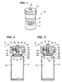
- the vial 10 includes a feature that allows an aliquot sample to be taken and isolated from the sample contained within the vial container 12.
- the vial 10 comprises a collection chamber 20 formed within the vial container 12 for collection of the sample, an aliquot chamber 22 for containing the aliquot sample, and a valve mechanism 24 for selectively sealing and unsealing the aliquot chamber 22 from the collection chamber 20, so the aliquot sample can be transferred from the collection chamber 20 into the aliquot chamber 22 where it can be isolated from the remaining portion of the sample within the collection chamber 20.
- the aliquot chamber 22 abuts the collection chamber 20, although alternatively, aliquot chamber 22 may communicate with the collection chamber 20 via, e.g., a passageway.
- the aliquot chamber 22 and valve mechanism 24 are carried by the vial cap 14.
- the vial cap 14 includes an outer annular flange 26, an inner annular flange 28, and an annular space 30 between the flanges 26, 28.
- the vial container 12 includes a lip 32 that is sized to fit within the annular space 30 of the vial cap 14 in a snug manner, so that the inner surface 34 of the outer annular flange 26 bears against the outer surface 36 of the vial container 12, and the outer surface 38 of the inner annular flange 28 bears against the inner surface 40 of the vial container 12, as best illustrated in Fig. 4 .
- the inner surface 34 of the outer annular flange 26 and the outer surface 36 of the vial container 12 include threads (not shown), so that the vial cap 14 can be firmly screwed on the vial container 12.
- the inner annular flange 28 of the vial cap 14 defines the aliquot chamber 22 therein, which absent the valve mechanism 24, would normally be in fluid communication with the collection chamber 20 when the vial cap 14 is mated with the vial container 12.
- the valve mechanism 24 includes a valve 42 that is configured to directly interface with the aliquot chamber 22 to allow or prevent fluid communication with the collection chamber 20.
- the valve 42 is configured to be selectively displaced from the aliquot chamber to allow fluid communication between the aliquot chamber 22 and the collection chamber 20 ( Fig. 2 ), and located within the aliquot chamber 22 to prevent fluid communication between the aliquot chamber 22 and the collection chamber 20 ( Fig. 3 ).
- the valve 42 when preventing fluid communication between the respective chambers 20, 22, the valve 42 sealingly bears against the inner surface 44 of the inner annular flange 28.
- the valve 42 includes an annular flange 46 that has a diameter slightly smaller than the diameter of the aliquot chamber 22 and an O-ring seal 48 seated within an annular recess 50 formed around the circumferential edge of the annular flange 46, so that the total diameter of the valve 42 is slightly greater than the diameter of the aliquot chamber 22 in order to facilitate the sealing arrangement.
- the valve mechanism 24 further includes an actuator 52, which includes a shaft 54 coupled to the valve 42 and a boss 56 coupled to the end of the shaft 54 and extending up through an upper bore 58 formed in the vial cap 14.
- the boss 56 can be externally manipulated to selectively displace the valve 42 from the aliquot chamber 22 by axially moving the actuator shaft 54 downward, and locate the valve 42 within the aliquot chamber 22 by axially moving the actuator shaft 54 upward.
- the annular flange 46 of the valve 42, the shaft 54, and the boss 56 may be conveniently formed from the same material as a unibody design, e.g., in an injection molding process using a plastic material, such as polypropylene or Acrylonitrile Butadiene Styrene (ABS).
- the valve mechanism 24 in order to prevent fluid communication between the aliquot chamber 22 and the external environment that may otherwise occur through the upper bore 58, the valve mechanism 24 includes an O-ring seal 60 seated within an annular recess 62 formed around the circumference of the shaft 54.
- the O-ring seal 60 axially moves within an enlarged lower bore 64 between the upper bore 58 and the aliquot chamber 22.
- the lower bore 64 is defined by an innermost annular flange 66 formed within the vial cap 14, so that the O-ring seal 60 bears against an inner surface 68 of the innermost annular flange 66.
- the O-ring seal 60 axially moves within the lower bore 64 in a sealing arrangement to allow the actuator shaft 54, and thus, the valve 42, to move up or down relative to aliquot chamber 22, while preventing fluid communication between the aliquot chamber 22 and the external environment through the upper bore 58.
- axial movement of the actuator shaft 54 is accomplished by rotationally translating the boss 56 (shown by arrow), and thus, the shaft 54, to operably move the valve 42 relative to the aliquot chamber 22.
- a threaded arrangement 70 is provided between the actuator shaft 54 and the upper bore 58.
- the boss 56 which is larger than the shaft 54, allows the user to more easily and ergonomically rotate the shaft 54 against any frictional resistance caused by the interaction of the valve 42 and aliquot chamber 22.
- the boss 56 can be further provided with a knurled surface (not shown) to facilitate gripping by the user.
- a slot or other suitable pattern can be formed at the end of the shaft 54 to allow a tool, such as a screw driver, to be mated with the shaft 54 for subsequent rotation thereof.
- the vial cap 14 includes an access port 72 adjacent the aliquot chamber 22 and a sealing mechanism in the form of septum 74 seated within the access port 72 to seal it, thereby preventing fluid communication from the aliquot chamber 22 through the access port 72 until the user is ready to remove the aliquot sample from the aliquot chamber 22 for examination.
- User access to the aliquot sample can be accomplished, e.g., by puncturing the septum 74 with a syringe (not shown) and drawing the aliquot sample from the chamber 22 into the syringe.
- a seal may be bonded on top surface of the vial cap 14 above the access port 72 or a screw-on plug or cap can be used to seal the access port 72.
- the vial cap 84 is identical to the vial cap 14 illustrated in Figs. 2 and 3 , which the exception that it comprises a valve mechanism 86, wherein the actuator shaft 54 is configured to be only axially translated, i.e., without rotational translation. In this case, there is no threaded arrangement between the shaft 54 and the upper bore 58. Rather, the actuator shaft 54 is slidably engaged with the bore 58 in the axial direction, so that a user may simply push or pull the shaft 54 to axially move the valve 42 relative to the aliquot chamber 22.
- the valve mechanism 86 comprises a spring 88 disposed between an annular flange 90 inwardly extending from the innermost annular flange 66 at the bottom of the enlarged lower bore 64 and an annular flange 92 outwardly extending from the actuator shaft 54 just below the O-ring seal 60.
- the spring 88 urges the actuator shaft 54 axially upward, and thus, the valve 42 into the aliquot chamber 22.
- the valve 42 urges the actuator shaft 54 axially upward, and thus, the valve 42 into the aliquot chamber 22.
- absence any external force fluid communication between the aliquot chamber 22 and the collection chamber 20 (shown in Figs. 2 and 3 ) is prevented.
- the valve 42 is displaced from the aliquot chamber 22, thereby allowing fluid communication between the aliquot chamber 22 and the collection chamber 20 ( Fig. 5 ).
- the boss 56 is eliminated, and the user need only push down or release the top of the actuator shaft 54.
- the end of the actuator shaft 54 may be recessed within the vial cap 84, in which case, the user may push down on the actuator shaft 54 using a simple tool.
- valve mechanisms selectively prevent fluid communication between the aliquot chamber 22 and collection chamber 20 by placing the valve within the aliquot chamber 22.
- the valve mechanism may have a valve that directly interfaces with the aliquot chamber 22 in other manners to prevent such fluid communication.
- the vial cap 94 is identical to the vial cap 14 illustrated in Figs. 2 and 3 , with the exception that it comprises a valve mechanism 96 that seals the aliquot chamber 22 at the interface with the collection chamber 20.
- the valve mechanism 96 comprises a valve 98 configured to be selectively displaced from a lower-most edge 100 of the inner annular flange 28 to allow fluid communication between the aliquot chamber 22 and the collection chamber 20 ( Fig. 7 ), and placed against the lower-most edge 100 of inner annular flange 28 to prevent fluid communication between aliquot chamber 22 and collection chamber 20 ( Fig. 8 ).
- the valve 98 When preventing fluid communication between the respective chambers, the valve 98 sealingly bears against the lower-most edge 100 of the inner annular flange 28.
- the valve 98 includes an annular flange 102 that has a diameter greater than the diameter of the aliquot chamber 22 and an O-ring seal 104 seated within an annular recess 106 within the upper surface of the flange 102, so that the O-ring seal 104 can contact the lower-most edge 100 of the inner annular flange 28 in order to facilitate the sealing arrangement.
- axial movement of the actuator shaft 54 is accomplished by rotationally translating the boss 56 (shown by arrow), and thus, the shaft 54, to operably move the valve 98 relative to the aliquot chamber 22. That is, clockwise rotation of the boss 56 causes the shaft 54, and thus the valve 98, to move axially downward, and counterclockwise rotation of the boss 56 causes the shaft 54, and thus the valve 98, to move axially upward.
- the valve mechanism may be configured, such that the shaft 54 need only be axially translated, i.e., without rotational translation.
- incorporation of the aliquot chamber and valve assembly into the vial cap allows the vial 10 to be stored upright in a standard manner without hindrance by any portion of the valve mechanism protruding from the vial and without risk that the remaining portion of the sample contained in the collection chamber 20 will leak into the aliquot chamber 22 with the vial 10 is stored upright.
- incorporation of the aliquot chamber into the vial cap provides the option of separating the vial cap containing the aliquot sample from the vial body, transferring the separated vial cap with the contained sample aliquot to a different location for molecular testing, and recapping and leaving the vial body at the cytological laboratory for producing a slide specimen or for any other reason.
- the vial 10 will need to be turned upside down to flow the sample aliquot from the collection chamber 20 into the aliquot chamber 22.
- separate sample indicia (not shown) be placed on the vial cap 14 in addition to the vial container 12 to eliminate or minimize the possibility that vial caps and vial containers will be incorrectly mated together.
- the vial 110 need not be turned upside down to flow the sample aliquot from the collection chamber into the aliquot chamber, and because the aliquot chamber is not incorporated into the vial cap, separate sample indicia is not required for the vial cap.
- the vial 110 comprises a hollow vial container 112 and a vial cap 114 that can be placed onto the vial container 112 to enclose a sample contained within the vial container 112.
- the vial container 112 and vial cap 114 are identical to the vial container 12 and vial cap 14 illustrated in Figs. 1-3 in all respects, with the following exceptions.
- the vial cap 114 may be a standard vial with includes a single annular flange 126 for mating with the top of the vial container 112.
- the vial 110 comprises a collection chamber 120 formed within the vial container 112 for collection of the sample, an aliquot chamber 122 for containing the aliquot sample, and a valve mechanism 124 for selectively sealing and unsealing the aliquot chamber 122 from the collection chamber 120, so the aliquot sample can be transferred from the collection chamber 120 into the aliquot chamber 122 where it can be isolated from the remaining portion of the sample within the collection chamber 120.
- the aliquot chamber 122 and valve mechanism 124 are carried by the vial container 112.
- an annular flange 128 is formed at the bottom of the vial container 112 to define the aliquot chamber 122, which absent the valve mechanism 124, would normally be in fluid communication with the collection chamber 120.
- the valve mechanism 124 includes a valve 142 that is configured to directly interface with the aliquot chamber 122 to allow or prevent fluid communication with the collection chamber 120.
- the valve 142 is configured to be selectively displaced from the aliquot chamber to allow fluid communication between the aliquot chamber 122 and the collection chamber 120 ( Fig. 9 ), and located within the aliquot chamber 122 to prevent fluid communication between the aliquot chamber 122 and the collection chamber 120 ( Fig. 10 ).
- valve 142 interfaces with the annular flange 128 in the same manner as the valve 42 interfaces with the inner annular flange 28 of the vial cap 14 illustrated in Figs. 2 and 3 . That is, as best shown in Fig. 11 , when preventing fluid communication between the respective chambers, the valve 142 sealingly bears against the inner surface 144 of the annular flange 128.
- the valve 142 includes an annular flange 146 that has a diameter slightly smaller than the diameter of the aliquot chamber 122 and an O-ring seal 148 seated within an annular recess 150 formed around the circumferential edge of the flange 146, so that the total diameter of the valve 142 is slightly greater than the diameter of the aliquot chamber 122 in order to facilitate the sealing arrangement.
- the annular flange 128 is set off from the outer wall of the vial container 112, the risk of interfering with the sealing relationship between the valve 142 and the inner surface 144 of the annular flange 128 is minimized. That is, if an inner annular flange is not used, and instead, the valve 142 sealingly interfaces with the inner surface of the outer wall of the vial container, the act of simply grasping the vial container may warp the outer wall, thereby breaking the sealing relationship between the valve 142 and outer wall. Alternatively, if the outer wall of the vial container 112 is sturdy enough, the valve 142 could be made to interface with the inner surface of the outer wall without risk of interfering with the sealing relationship.
- the valve mechanism 124 further includes an actuator 152, which includes a shaft 154 coupled to the valve 142 and extending through a lower bore 158 formed at the bottom of the vial container 112.
- the actuator 152 does not include a boss or any part that protrudes from the vial container, so that the bottom surface of the vial 110 is flush or recessed to facilitate the storage of the vial 110 in an upright manner.
- the shaft 154 is configured, such that a tool can be used to externally manipulate the valve mechanism 124 to selectively locate the valve 142 within the aliquot chamber 122 and displace the valve 142 from the aliquot chamber 122, as will be described in further detail below.
- the annular flange 146 of the valve 142 and the shaft 154 may be conveniently formed from the same material as a unibody design, e.g., in an injection molding process using a plastic material, such as polypropylene.
- the valve mechanism 124 in order to prevent fluid communication between the aliquot chamber 122 and the external environment that may otherwise occur through the lower bore 158, the valve mechanism 124 includes an O-ring seal 160 seated within an annular recess 162 formed around the circumference of the shaft 154.
- the O-ring seal 160 axially moves within an enlarged upper bore 164 between the lower bore 158 and the aliquot chamber 122.
- the upper bore 164 is defined by an inner annular flange 166 formed within vial container 112, so that the O-ring seal 160 bears against an inner surface 168 of the inner annular flange 166.
- the O-ring seal 160 axially moves within the upper bore 164 in a sealing arrangement to allow the actuator shaft 154, and thus, the valve 142, to move up or down relative to aliquot chamber 122, while preventing fluid communication between the aliquot chamber 122 and the external environment through the lower bore 158.
- axial movement of the actuator shaft 154 is accomplished in the same manner as the actuator shaft 54 described with respect to Figs. 2 and 3 . That is, the actuator shaft 154 may be rotationally translated to operably move the valve 142 relative to the aliquot chamber 122. To this end, a threaded arrangement 170 is provided between the actuator shaft 154 and the upper bore 158.
- clockwise rotation of the shaft 154 causes the valve 142 to move axially upward
- counterclockwise rotation of the shaft 154 causes the valve 142 to move axially downward.
- a slot or other suitable pattern is formed at the end of the shaft 154 to allow a tool, such as a screw driver, to be mated with the shaft 154 for subsequent rotation thereof.
- valve mechanism may be configured, such that the shaft 154 need only be axially translated, i.e., without rotational translation.
- valve mechanism may be configured, such that the valve seals the aliquot chamber 122 at the interface with the collection chamber 120, e.g., creating a seal between the upper-most edge of the inner annular flange 128 and a valve.
- the vial container 112 includes an access port 172 adjacent the aliquot chamber 122 and a sealing mechanism in the form of septum 174 seated within the access port 172 to seal it, thereby preventing fluid communication from the aliquot chamber 122 through the access port 172 until the user is ready to remove the aliquot sample from the aliquot chamber 122 for examination.
- User access to the aliquot sample can be accomplished, e.g., by puncturing the septum 174 with a syringe and drawing the aliquot sample from the aliquot chamber 122 into the syringe.
- a seal may be bonded on top surface of the vial cap 114 above the access port 172 or a screw-on plug or cap can be used to seal the access port 172.
- a method of processing a vial will now be described with reference to Fig. 12 .
- the illustrated method will be described in the context of triaging patients for precursors of cervical cancer.
- the vial cap is removed from the vial container and a fluid-based cervical-vaginal sample is placed within the collection chamber of the vial container (step 200).
- This step can typically be accomplished at the physician's office.
- the cervical-vaginal sample is taken as part of the routine Pap smear.
- cells are scraped from the cervix of the patient and mixed into a preservative solution, such as PreservCyt® transport medium, contained within the collection chamber of the vial container.
- the vial cap is placed back on the vial container, and the vial with the collected fluid-based sample, is transferred to a cytological laboratory (step 202).
- the fluid-based sample is agitated to disburse the cells (step 204), and the aliquot chamber in the vial is unsealed from the collection chamber while the vial cap is mated with the vial container (step 206).
- this is accomplished by rotating the boss 56 on the vial cap 14 in the clockwise direction to displace the valve 42 out of the aliquot chamber 22.
- this is accomplished by pushing the boss 56 on the vial cap 84 downward against the urging force of the spring 88 to displace the valve 42 out of the aliquot chamber 22.
- Figs. 2 and 3 this is accomplished by rotating the boss 56 on the vial cap 14 in the clockwise direction to displace the valve 42 out of the aliquot chamber 22.
- this is accomplished by pushing the boss 56 on the vial cap 84 downward against the urging force of the spring 88 to displace the valve 42 out of the aliquot chamber 22.
- an aliquot of the sample is flowed from the collection chamber into the unsealed aliquot chamber while the sample is isolated from an environment exterior to the vial (i.e., while the vial cap is mated with the vial container) (step 208).
- the aliquot chamber is integrated into the vial cap, such as the embodiments illustrated in Figs. 2 and 3 , Figs. 5 and 6, and Figs. 7 and 8, and Figs. 9 and 10
- this can be accomplished by flipping the vials upside down.
- the aliquot of the sample will flow from the collection chamber into the aliquot chamber in response to unsealing the aliquot chamber from the collection chamber in step 204.
- the agitation, unsealing, and flowing steps 204, 206, 208 can be performed at the physician's office prior to transferring the respective vial to the cytological laboratory.
- the aliquot chamber is sealed from the collection chamber to isolate the aliquot chamber from the remaining portion of the sample contained in the collection chamber (step 210).
- this is accomplished by rotating the boss 56 on the vial cap 14 in the counterclockwise direction to relocate the valve 42 into the aliquot chamber 22.
- this is accomplished simply be relieving downward pressure from the boss 56 on the vial cap 84, and allowing the urging force of the spring 88 to move the valve 42 back into the aliquot chamber 22.
- Figs. 2 and 3 this is accomplished by rotating the boss 56 on the vial cap 14 in the counterclockwise direction to relocate the valve 42 into the aliquot chamber 22.
- this is accomplished simply be relieving downward pressure from the boss 56 on the vial cap 84, and allowing the urging force of the spring 88 to move the valve 42 back into the aliquot chamber 22.
- the vial cap is unmated from the vial container to expose, and thereby provide access, to the remaining sample portion in the collection chamber (step 212), and at least some of the remaining sample portion is transferred from the collection chamber to a microscope slide while the aliquot chamber is sealed from the collection chamber (step 214).
- exposing the collection chamber to the external environment may expose the remaining sample portion to contaminants (e.g., HPV) at the molecular level. This may be especially true if the slide preparation process is performed by an automated specimen preparation system where molecular contaminants are often found. Without taking additional precautions, such molecular contaminants can be found in an aerosol or within filtered cell solution in the plumbing of the automated specimen preparation system where it can be transferred from vial to vial.
- contaminants e.g., HPV
- the slide specimen is reserved for cytological screening of the sample for precursors of cervical cancers (step 216), and the sample aliquot is reserved for DNA testing, e.g., for the present of high-risk HPV in the sample (step 218).
- the slide is cytological screened, e.g., for precursors of cervical cancers (step 220). This can be accomplished in the same laboratory at which the slide was prepared, or alternatively, can be transferred to another laboratory.
- the patient is returned to a routine Pap smear schedule (step 222).
- the patient is scheduled for a colposcopy/biopsy at the physician's office (step 224).
- the aliquot sample is removed from the aliquot chamber via the access port within the vial cap or vial container (step 226), and a reflex DNA test is performed on the aliquot sample reserved in step 218 for the presence of high-risk HPV (step 228).
- a reflex DNA test is performed on the aliquot sample reserved in step 218 for the presence of high-risk HPV (step 228).
- This can be accomplished using Digene's Hybrid Capture II HPV DNA assay. If the presence of high-risk HPV is detected in the sample, the patient is scheduled for a colposcopy/biopsy at the physician's office (step 230), or alternatively may be placed on a schedule with increased Pap smear intervals.
- the patient may then be returned to a routine Pap smear schedule (step 232).
- other DNA tests e.g., to detect the presence of such as Chlamydia trachomatis and Neisseria gonorrhoeae, may be performed. These other DNA tests, or even the HPV DNA test, can be alternatively performed in parallel with the cytological screening of the slide.
Landscapes
- Health & Medical Sciences (AREA)
- Chemical & Material Sciences (AREA)
- Clinical Laboratory Science (AREA)
- Chemical Kinetics & Catalysis (AREA)
- Analytical Chemistry (AREA)
- General Health & Medical Sciences (AREA)
- Hematology (AREA)
- Sampling And Sample Adjustment (AREA)
- Automatic Analysis And Handling Materials Therefor (AREA)
- Apparatus Associated With Microorganisms And Enzymes (AREA)
Claims (8)
- Probengefäß (10) umfassend:eine Sammelkammer (20) zum Aufbewahren einer flüssigkeitsbasierten zytologischen Probe;einen Ventilmechanismus (24);eine Teilprobenkammer (22);eine abgedichtete Zugangsöffnung (72), die einen Zugang zwischen der Teilprobenkammer und dem Äußeren des Gefäß bereitstellt; undeinen Gefäßdeckel (14) ausgebildet, um mit dem Gefäß zusammenzupassen, um die Sammelkammer einzuschließen, wobei der Ventilmechanismus eine Wand der Teilprobenkammer umfasst oder daran gekoppelt ist und vorgespannt ist die Teilprobenkammer von der Sammelkammer abzudichten, außer er ist aktiv betätigt, um die Teilprobenkammer von der Sammelkammer zu lösen und dadurch einer Teilprobe der Probe zu ermöglichen aus der Sammelkammer in die Teilprobenkammer zu fließen, während die Sammelkammer von einer Umgebung außerhalb des Gefäßes isoliert ist, und, falls er nicht aktiv betätigt ist, der vorgespannte Ventilmechanismus die Teilprobenkammer automatisch von der Sammelkammer abdichtet, um die Teilprobe von einer verbleibenden Menge der Probe in der Sammelkammer zu isolieren, und wobei der Ventilmechanismus von außen betätigt werden kann, um die Teilprobenkammer von der Sammelkammer wahlweise abzudichten und zu lösen.
- Probengefäß (10) nach Anspruch 1, wobei das Gefäß einen Gefäßbehälter (12), der die Sammelkammer (20) trägt, aufweist und der Gefäßdeckel (14) zu dem Gefäßbehälter passt, so dass ein Lösen des Gefäßdeckels von dem Gefäßbehälter eine verbleibende Probenmenge in der Sammelkammer freisetzt.
- Probengefäß (10) nach Anspruch 1, wobei die Teilprobenkammer (22) von dem Gefäßdeckel (14) getragen wird.
- Verfahren zum Verwenden eines Gefäßes (10) mit einer Sammelkammer (20), die eine flüssigkeitsbasierte Probe enthält, einem Ventilmechanismus (24), einer Teilprobenkammer (22), einer abgedichteten Zugangsöffnung (72), die einen Zugang zwischen der Teilprobenkammer und dem Äußeren des Gefäßes bereitstellt, und einem Gefäßdeckel (14), ausgebildet um mit dem Gefäß zu passen, um die Sammelkammer einzuschließen, wobei der Ventilmechanismus eine Wand der Teilprobenkammer umfasst oder daran gekoppelt ist, und wobei der Ventilmechanismus vorgespannt ist die Teilprobenkammer von der Sammelkammer abzudichten, außer er wird aktiv betätigt, wobei das Verfahren umfasst:Betätigen des Ventilmechanismus von außen, um die Teilprobenkammer von der Sammelkammer zu lösen;Fließen einer Teilprobe der Probe aus der Sammelkammer in die Teilprobenkammer, während die Sammelkammer von einer Umgebung außerhalb des Gefäßes isoliert ist;Beenden einer aktiven Aktivierung des Ventilmechanismus, wobei der vorgespannte Ventilmechanismus die Teilkammer automatisch von der Sammelkammer abdichtet, um die Teilprobe von der verbleibenden Menge der Probe in der Sammelkammer zu isolieren; undEntfernen von zumindest etwas der verbleibenden Probenmenge aus der Sammelkammer, während die Teilprobenkammer von der Sammelkammer abgedichtet ist.
- Verfahren nach Anspruch 4, wobei die flüssigkeitsbasierte Probe eine zervikalvaginale Probe ist.
- Verfahren nach Anspruch 4 oder 5, wobei das zumindest etwas der verbleibenden Probenmenge auf einem Mikroskopobjektträger übertragen wird.
- Verfahren nach einem der Ansprüche 4 bis 6, ferner umfassend Ausführen einer zytologischen Untersuchung der entfernten verbleibenden Probenmenge.
- Verfahren nach Anspruch 7, ferner umfassend Ausführen eines Desoxynukleinsäure (DNS) Tests der Teilprobe.
Applications Claiming Priority (3)
| Application Number | Priority Date | Filing Date | Title |
|---|---|---|---|
| US11/299,394 US7686771B2 (en) | 2005-12-12 | 2005-12-12 | Method and apparatus for obtaining aliquot from liquid-based cytological sample |
| US11/530,300 US20070140915A1 (en) | 2005-12-12 | 2006-09-08 | Method and Apparatus for Obtaining Aliquot from Liquid-Based Cytological Sample |
| PCT/US2006/061360 WO2007070740A2 (en) | 2005-12-12 | 2006-11-29 | Method and apparatus for obtaining aliquot from liquid-based cytological sample |
Publications (2)
| Publication Number | Publication Date |
|---|---|
| EP1963017A2 EP1963017A2 (de) | 2008-09-03 |
| EP1963017B1 true EP1963017B1 (de) | 2011-05-18 |
Family
ID=38163581
Family Applications (1)
| Application Number | Title | Priority Date | Filing Date |
|---|---|---|---|
| EP06848603A Not-in-force EP1963017B1 (de) | 2005-12-12 | 2006-11-29 | Verfahren und vorrichtung zum entnehmen einer probe aus einer flüssigkeitbasierten zytologischen probe |
Country Status (9)
| Country | Link |
|---|---|
| US (1) | US20070140915A1 (de) |
| EP (1) | EP1963017B1 (de) |
| JP (1) | JP5595662B2 (de) |
| AT (1) | ATE509698T1 (de) |
| AU (1) | AU2006325850B2 (de) |
| CA (1) | CA2629049C (de) |
| DK (1) | DK1963017T3 (de) |
| TW (1) | TWI330713B (de) |
| WO (1) | WO2007070740A2 (de) |
Families Citing this family (17)
| Publication number | Priority date | Publication date | Assignee | Title |
|---|---|---|---|---|
| US7947450B2 (en) | 2003-07-10 | 2011-05-24 | Universite Libre De Bruxelles | Device, kit and method for pulsing biological samples with an agent and stabilising the sample so pulsed |
| JP4472634B2 (ja) | 2003-07-10 | 2010-06-02 | ユニヴェルシテ リブル ドゥ ブリュッセル | 生物学的試料を試剤でパルスし、こうしてパルスされた試料を安定化するための装置、キット及び方法 |
| EP2249701B1 (de) | 2008-03-05 | 2020-04-29 | Becton, Dickinson and Company | Sammelbehälteranordnung mit kapillarwirkung |
| CN102186590A (zh) * | 2008-10-17 | 2011-09-14 | 布鲁塞尔自由大学 | 用于用试剂使生物样品脉动和稳定如此脉动的样品的装置、试剂盒和方法 |
| US20110178424A1 (en) * | 2010-01-19 | 2011-07-21 | Becton, Dickinson And Company | Specimen Collection Container Having a Transitional Fill-Volume Indicator Indicating Extraction Method |
| CN105044320B (zh) * | 2010-03-25 | 2017-02-22 | 艾博生物医药(杭州)有限公司 | 测试液体样本中被分析物的检测装置 |
| EP2617362B1 (de) | 2012-01-20 | 2019-04-10 | Bühlmann Laboratories AG | Probenentnahme-, Verdünnungs- und Ausgabevorrichtung |
| DE102012208707A1 (de) * | 2012-05-24 | 2013-12-12 | Hamilton Bonaduz Ag | Probenverarbeitungssystem zum Verarbeiten von biologischen Proben |
| DE102013207678A1 (de) * | 2013-05-29 | 2014-12-04 | Robert Bosch Gmbh | Deckelkonstruktion zur Anwendungserweiterung, sowie Kartusche mit Deckelkonstruktion |
| AU2016221780B2 (en) * | 2015-02-20 | 2019-09-12 | Ventana Medical Systems, Inc. | Assembly for storing and transporting tissue samples immersed in a fluid |
| CN108792258A (zh) * | 2018-05-21 | 2018-11-13 | 南京申友生物技术有限公司 | 一种基因检测用试剂盒 |
| AU2019341671B2 (en) * | 2018-09-21 | 2024-06-20 | Foss Analytical A/S | A sampling device, a system comprising the sampling device and a method |
| WO2020106891A1 (en) | 2018-11-20 | 2020-05-28 | Spectrum Solutions, Llc | Sample collection system including sealing cap and valve |
| US20200391203A1 (en) * | 2019-06-13 | 2020-12-17 | Roger Wallace Giese | Low-alcohol jar for serial saliva and breath metabolomics |
| US11701094B2 (en) | 2019-06-20 | 2023-07-18 | Spectrum Solutions L.L.C. | Sample collection system including valve and plug assemblies |
| US11976262B2 (en) | 2019-08-27 | 2024-05-07 | Battelle Memorial Institute | Biological culture unit |
| CN117561029A (zh) * | 2021-05-14 | 2024-02-13 | 北京大学 | 用于处理和保存流体生物样本的容器、与该容器相关的设备和试剂盒 |
Family Cites Families (26)
| Publication number | Priority date | Publication date | Assignee | Title |
|---|---|---|---|---|
| US416435A (en) * | 1889-12-03 | Li quid-meter | ||
| JPS5934346U (ja) * | 1982-08-30 | 1984-03-03 | 住友ベークライト株式会社 | 試料採取装置 |
| US4886193A (en) * | 1986-07-08 | 1989-12-12 | Creanova Ag. | Container closure cap with metering appliance |
| JPH0454926Y2 (de) | 1986-11-19 | 1992-12-24 | ||
| US4927605A (en) * | 1987-04-22 | 1990-05-22 | Wadley Technologies, Inc. | Specimen collection and sampling container |
| US5429803A (en) * | 1991-04-18 | 1995-07-04 | Lamina, Inc. | Liquid specimen container and attachable testing modules |
| EP0609431B1 (de) * | 1992-08-24 | 1997-10-08 | Dade MicroScan Inc. | Abdichtbarer behälter zum konservieren und behandeln analytischer proben |
| JPH0829432A (ja) * | 1994-07-15 | 1996-02-02 | Shimadzu Corp | 自動試料調製装置 |
| US6277646B1 (en) * | 1997-05-05 | 2001-08-21 | Dade Behring Inc. | Fluid specimen collecting and testing apparatus |
| US5975373A (en) * | 1997-07-21 | 1999-11-02 | Starplex Scientific | Liquid sample collection and transport system |
| US20030059347A1 (en) * | 1998-09-18 | 2003-03-27 | Roy A. Ostgaard | Sample vial for use in preparing cytological specimen |
| US7569344B2 (en) * | 1998-10-26 | 2009-08-04 | Ventana Medical Systems, Inc. | Detection of human papilloma virus in papanicolaou (Pap) smears |
| JP2001194365A (ja) * | 1999-11-05 | 2001-07-19 | Sekisui Chem Co Ltd | 細胞機能測定容器及び細胞機能測定方法 |
| US6393926B1 (en) * | 2000-05-19 | 2002-05-28 | Accutrol Co., Inc. | Front-loading precision material sampler with interchangeable retracting chamber |
| WO2003034035A1 (en) * | 2001-10-19 | 2003-04-24 | Monogen, Inc. | Vial system and method for processing liquid-based specimens |
| WO2003034076A1 (en) * | 2001-10-19 | 2003-04-24 | Monogen, Inc. | Article handling system and method |
| EP1478278A1 (de) * | 2002-02-17 | 2004-11-24 | Novamed Ltd. | Sammel- und probenbehälter für biologische flüssigkeit |
| JP3994129B2 (ja) * | 2002-04-22 | 2007-10-17 | 独立行政法人放射線医学総合研究所 | サンプル用ラベルの使用方法、及び被検者匿名化方法 |
| JP3599726B2 (ja) * | 2002-08-30 | 2004-12-08 | 康克 井野内 | 微量液体吸入吐出装置 |
| GB0222855D0 (en) * | 2002-10-03 | 2002-11-06 | Secr Defence | Sampling apparatus |
| US20040137551A1 (en) * | 2003-01-13 | 2004-07-15 | Markovic Nenad S. | Cervical acid phosphatase - papanicolaou (CAP-PAP) test kit, method and accesories, processes for producing and using the same |
| EP1656205B1 (de) * | 2003-08-05 | 2010-06-16 | Becton, Dickinson and Company | Vorrichtung und verfahren zum sammeln von biologischen fluidproben und zur behandlung von ausgewählten komponenten |
| EP1687621B1 (de) * | 2003-11-14 | 2018-06-27 | Alere Switzerland GmbH | Probensammelgefäss mit integriertem aktivierbarem probenanalysesystem |
| JP2005162290A (ja) * | 2003-12-04 | 2005-06-23 | Nippon Kosan:Kk | 計量容器 |
| JP4367698B2 (ja) * | 2004-01-30 | 2009-11-18 | 株式会社吉野工業所 | 定量塗布容器 |
| KR20080075045A (ko) * | 2004-03-24 | 2008-08-13 | 트리패스 이미징, 인코포레이티드 | 자궁경부 질환의 검사 방법 및 조성물 |
-
2006
- 2006-09-08 US US11/530,300 patent/US20070140915A1/en not_active Abandoned
- 2006-11-29 JP JP2008544610A patent/JP5595662B2/ja not_active Expired - Fee Related
- 2006-11-29 EP EP06848603A patent/EP1963017B1/de not_active Not-in-force
- 2006-11-29 CA CA2629049A patent/CA2629049C/en not_active Expired - Fee Related
- 2006-11-29 DK DK06848603.4T patent/DK1963017T3/da active
- 2006-11-29 WO PCT/US2006/061360 patent/WO2007070740A2/en not_active Ceased
- 2006-11-29 AU AU2006325850A patent/AU2006325850B2/en not_active Ceased
- 2006-11-29 AT AT06848603T patent/ATE509698T1/de not_active IP Right Cessation
- 2006-12-11 TW TW095146297A patent/TWI330713B/zh not_active IP Right Cessation
Also Published As
| Publication number | Publication date |
|---|---|
| DK1963017T3 (da) | 2011-09-12 |
| JP2009519439A (ja) | 2009-05-14 |
| CA2629049A1 (en) | 2007-06-21 |
| HK1114577A1 (en) | 2008-11-07 |
| AU2006325850B2 (en) | 2011-09-29 |
| WO2007070740A2 (en) | 2007-06-21 |
| TW200732664A (en) | 2007-09-01 |
| JP5595662B2 (ja) | 2014-09-24 |
| AU2006325850A1 (en) | 2007-06-21 |
| CA2629049C (en) | 2014-04-29 |
| EP1963017A2 (de) | 2008-09-03 |
| WO2007070740A3 (en) | 2007-10-04 |
| TWI330713B (en) | 2010-09-21 |
| US20070140915A1 (en) | 2007-06-21 |
| ATE509698T1 (de) | 2011-06-15 |
Similar Documents
| Publication | Publication Date | Title |
|---|---|---|
| US8137289B2 (en) | Method and apparatus for obtaining aliquot from liquid-based cytological sample | |
| AU2007325309B2 (en) | Vials and apparatus for obtaining an aliquot of a sample | |
| AU2006325850B2 (en) | Method and apparatus for obtaining aliquot from liquid-based cytological sample | |
| IL282867B (en) | Systems and methods for automatic preparation of biological samples | |
| CN101848767A (zh) | 用于分子和组织诊断学的流体移位组织容器 | |
| JP2013145253A (ja) | 試料保持器のための支持アセンブリ、該支持アセンブリを備える閉鎖アセンブリ、試料保持器収容部材、および、試料保持器とその収容部材とを備えるアセンブリ | |
| US20060039833A1 (en) | Biological specimen collection, transportation, and dispensing system | |
| CN1842299A (zh) | 生物样本收集和分析系统 | |
| US20070025886A1 (en) | Biological specimen collection, transportation, and dispensing system | |
| HK1114577B (en) | Method and apparatus for obtaining aliquot from liquid-based cytological sample | |
| JP2005506532A (ja) | 液体ベースの標本を処理するためのバイアルシステム、および方法 | |
| JP2003057233A (ja) | 真空の管および尿沈殿物の顕微鏡検査、化学及び微生物の分析のための方法 | |
| HK1129340B (en) | Vials and apparatus for obtaining an aliquot of a sample |
Legal Events
| Date | Code | Title | Description |
|---|---|---|---|
| PUAI | Public reference made under article 153(3) epc to a published international application that has entered the european phase |
Free format text: ORIGINAL CODE: 0009012 |
|
| 17P | Request for examination filed |
Effective date: 20080606 |
|
| AK | Designated contracting states |
Kind code of ref document: A2 Designated state(s): AT BE BG CH CY CZ DE DK EE ES FI FR GB GR HU IE IS IT LI LT LU LV MC NL PL PT RO SE SI SK TR |
|
| REG | Reference to a national code |
Ref country code: HK Ref legal event code: DE Ref document number: 1114577 Country of ref document: HK |
|
| 17Q | First examination report despatched |
Effective date: 20100217 |
|
| GRAP | Despatch of communication of intention to grant a patent |
Free format text: ORIGINAL CODE: EPIDOSNIGR1 |
|
| GRAS | Grant fee paid |
Free format text: ORIGINAL CODE: EPIDOSNIGR3 |
|
| GRAA | (expected) grant |
Free format text: ORIGINAL CODE: 0009210 |
|
| REG | Reference to a national code |
Ref country code: GB Ref legal event code: FG4D |
|
| REG | Reference to a national code |
Ref country code: CH Ref legal event code: EP |
|
| REG | Reference to a national code |
Ref country code: IE Ref legal event code: FG4D |
|
| REG | Reference to a national code |
Ref country code: DE Ref legal event code: R096 Ref document number: 602006022105 Country of ref document: DE Effective date: 20110630 |
|
| REG | Reference to a national code |
Ref country code: NL Ref legal event code: T3 |
|
| REG | Reference to a national code |
Ref country code: CH Ref legal event code: NV Representative=s name: KELLER & PARTNER PATENTANWAELTE AG |
|
| REG | Reference to a national code |
Ref country code: HK Ref legal event code: GR Ref document number: 1114577 Country of ref document: HK |
|
| REG | Reference to a national code |
Ref country code: SE Ref legal event code: TRGR |
|
| REG | Reference to a national code |
Ref country code: DK Ref legal event code: T3 |
|
| REG | Reference to a national code |
Ref country code: GR Ref legal event code: EP Ref document number: 20110401955 Country of ref document: GR Effective date: 20110916 Ref country code: ES Ref legal event code: FG2A Ref document number: 2366739 Country of ref document: ES Kind code of ref document: T3 Effective date: 20111025 |
|
| PG25 | Lapsed in a contracting state [announced via postgrant information from national office to epo] |
Ref country code: PT Free format text: LAPSE BECAUSE OF FAILURE TO SUBMIT A TRANSLATION OF THE DESCRIPTION OR TO PAY THE FEE WITHIN THE PRESCRIBED TIME-LIMIT Effective date: 20110919 Ref country code: LT Free format text: LAPSE BECAUSE OF FAILURE TO SUBMIT A TRANSLATION OF THE DESCRIPTION OR TO PAY THE FEE WITHIN THE PRESCRIBED TIME-LIMIT Effective date: 20110518 |
|
| PG25 | Lapsed in a contracting state [announced via postgrant information from national office to epo] |
Ref country code: AT Free format text: LAPSE BECAUSE OF FAILURE TO SUBMIT A TRANSLATION OF THE DESCRIPTION OR TO PAY THE FEE WITHIN THE PRESCRIBED TIME-LIMIT Effective date: 20110518 Ref country code: FI Free format text: LAPSE BECAUSE OF FAILURE TO SUBMIT A TRANSLATION OF THE DESCRIPTION OR TO PAY THE FEE WITHIN THE PRESCRIBED TIME-LIMIT Effective date: 20110518 Ref country code: CY Free format text: LAPSE BECAUSE OF FAILURE TO SUBMIT A TRANSLATION OF THE DESCRIPTION OR TO PAY THE FEE WITHIN THE PRESCRIBED TIME-LIMIT Effective date: 20110518 Ref country code: SI Free format text: LAPSE BECAUSE OF FAILURE TO SUBMIT A TRANSLATION OF THE DESCRIPTION OR TO PAY THE FEE WITHIN THE PRESCRIBED TIME-LIMIT Effective date: 20110518 Ref country code: IS Free format text: LAPSE BECAUSE OF FAILURE TO SUBMIT A TRANSLATION OF THE DESCRIPTION OR TO PAY THE FEE WITHIN THE PRESCRIBED TIME-LIMIT Effective date: 20110918 Ref country code: LV Free format text: LAPSE BECAUSE OF FAILURE TO SUBMIT A TRANSLATION OF THE DESCRIPTION OR TO PAY THE FEE WITHIN THE PRESCRIBED TIME-LIMIT Effective date: 20110518 |
|
| PG25 | Lapsed in a contracting state [announced via postgrant information from national office to epo] |
Ref country code: CZ Free format text: LAPSE BECAUSE OF FAILURE TO SUBMIT A TRANSLATION OF THE DESCRIPTION OR TO PAY THE FEE WITHIN THE PRESCRIBED TIME-LIMIT Effective date: 20110518 Ref country code: EE Free format text: LAPSE BECAUSE OF FAILURE TO SUBMIT A TRANSLATION OF THE DESCRIPTION OR TO PAY THE FEE WITHIN THE PRESCRIBED TIME-LIMIT Effective date: 20110518 |
|
| PG25 | Lapsed in a contracting state [announced via postgrant information from national office to epo] |
Ref country code: SK Free format text: LAPSE BECAUSE OF FAILURE TO SUBMIT A TRANSLATION OF THE DESCRIPTION OR TO PAY THE FEE WITHIN THE PRESCRIBED TIME-LIMIT Effective date: 20110518 Ref country code: PL Free format text: LAPSE BECAUSE OF FAILURE TO SUBMIT A TRANSLATION OF THE DESCRIPTION OR TO PAY THE FEE WITHIN THE PRESCRIBED TIME-LIMIT Effective date: 20110518 Ref country code: RO Free format text: LAPSE BECAUSE OF FAILURE TO SUBMIT A TRANSLATION OF THE DESCRIPTION OR TO PAY THE FEE WITHIN THE PRESCRIBED TIME-LIMIT Effective date: 20110518 |
|
| PLBE | No opposition filed within time limit |
Free format text: ORIGINAL CODE: 0009261 |
|
| STAA | Information on the status of an ep patent application or granted ep patent |
Free format text: STATUS: NO OPPOSITION FILED WITHIN TIME LIMIT |
|
| 26N | No opposition filed |
Effective date: 20120221 |
|
| REG | Reference to a national code |
Ref country code: DE Ref legal event code: R097 Ref document number: 602006022105 Country of ref document: DE Effective date: 20120221 |
|
| PG25 | Lapsed in a contracting state [announced via postgrant information from national office to epo] |
Ref country code: MC Free format text: LAPSE BECAUSE OF NON-PAYMENT OF DUE FEES Effective date: 20111130 |
|
| GBPC | Gb: european patent ceased through non-payment of renewal fee |
Effective date: 20111129 |
|
| REG | Reference to a national code |
Ref country code: GB Ref legal event code: S28 Free format text: APPLICATION FILED |
|
| PG25 | Lapsed in a contracting state [announced via postgrant information from national office to epo] |
Ref country code: GB Free format text: LAPSE BECAUSE OF NON-PAYMENT OF DUE FEES Effective date: 20111129 |
|
| REG | Reference to a national code |
Ref country code: GB Ref legal event code: S28 Free format text: RESTORATION ALLOWED Effective date: 20121031 |
|
| PGFP | Annual fee paid to national office [announced via postgrant information from national office to epo] |
Ref country code: DK Payment date: 20121126 Year of fee payment: 7 |
|
| PGFP | Annual fee paid to national office [announced via postgrant information from national office to epo] |
Ref country code: GR Payment date: 20121128 Year of fee payment: 7 Ref country code: BE Payment date: 20121129 Year of fee payment: 7 Ref country code: SE Payment date: 20121126 Year of fee payment: 7 |
|
| PG25 | Lapsed in a contracting state [announced via postgrant information from national office to epo] |
Ref country code: LU Free format text: LAPSE BECAUSE OF NON-PAYMENT OF DUE FEES Effective date: 20111129 |
|
| PG25 | Lapsed in a contracting state [announced via postgrant information from national office to epo] |
Ref country code: BG Free format text: LAPSE BECAUSE OF FAILURE TO SUBMIT A TRANSLATION OF THE DESCRIPTION OR TO PAY THE FEE WITHIN THE PRESCRIBED TIME-LIMIT Effective date: 20110818 |
|
| PG25 | Lapsed in a contracting state [announced via postgrant information from national office to epo] |
Ref country code: TR Free format text: LAPSE BECAUSE OF FAILURE TO SUBMIT A TRANSLATION OF THE DESCRIPTION OR TO PAY THE FEE WITHIN THE PRESCRIBED TIME-LIMIT Effective date: 20110518 |
|
| PG25 | Lapsed in a contracting state [announced via postgrant information from national office to epo] |
Ref country code: HU Free format text: LAPSE BECAUSE OF FAILURE TO SUBMIT A TRANSLATION OF THE DESCRIPTION OR TO PAY THE FEE WITHIN THE PRESCRIBED TIME-LIMIT Effective date: 20110518 |
|
| BERE | Be: lapsed |
Owner name: CYTYC CORP. Effective date: 20131130 |
|
| REG | Reference to a national code |
Ref country code: DK Ref legal event code: EBP Effective date: 20131130 |
|
| REG | Reference to a national code |
Ref country code: SE Ref legal event code: EUG |
|
| REG | Reference to a national code |
Ref country code: GR Ref legal event code: ML Ref document number: 20110401955 Country of ref document: GR Effective date: 20140603 |
|
| PG25 | Lapsed in a contracting state [announced via postgrant information from national office to epo] |
Ref country code: GR Free format text: LAPSE BECAUSE OF NON-PAYMENT OF DUE FEES Effective date: 20140603 Ref country code: SE Free format text: LAPSE BECAUSE OF NON-PAYMENT OF DUE FEES Effective date: 20131130 |
|
| PG25 | Lapsed in a contracting state [announced via postgrant information from national office to epo] |
Ref country code: BE Free format text: LAPSE BECAUSE OF NON-PAYMENT OF DUE FEES Effective date: 20131130 |
|
| PG25 | Lapsed in a contracting state [announced via postgrant information from national office to epo] |
Ref country code: DK Free format text: LAPSE BECAUSE OF NON-PAYMENT OF DUE FEES Effective date: 20131130 |
|
| REG | Reference to a national code |
Ref country code: CH Ref legal event code: PCAR Free format text: NEW ADDRESS: EIGERSTRASSE 2 POSTFACH, 3000 BERN 14 (CH) |
|
| REG | Reference to a national code |
Ref country code: FR Ref legal event code: PLFP Year of fee payment: 10 |
|
| REG | Reference to a national code |
Ref country code: FR Ref legal event code: PLFP Year of fee payment: 11 |
|
| PGFP | Annual fee paid to national office [announced via postgrant information from national office to epo] |
Ref country code: FR Payment date: 20161123 Year of fee payment: 11 Ref country code: DE Payment date: 20161123 Year of fee payment: 11 Ref country code: IE Payment date: 20161123 Year of fee payment: 11 Ref country code: NL Payment date: 20161126 Year of fee payment: 11 Ref country code: CH Payment date: 20161128 Year of fee payment: 11 Ref country code: GB Payment date: 20161128 Year of fee payment: 11 |
|
| PGFP | Annual fee paid to national office [announced via postgrant information from national office to epo] |
Ref country code: ES Payment date: 20161128 Year of fee payment: 11 Ref country code: IT Payment date: 20161124 Year of fee payment: 11 |
|
| REG | Reference to a national code |
Ref country code: DE Ref legal event code: R119 Ref document number: 602006022105 Country of ref document: DE |
|
| REG | Reference to a national code |
Ref country code: NL Ref legal event code: MM Effective date: 20171201 |
|
| GBPC | Gb: european patent ceased through non-payment of renewal fee |
Effective date: 20171129 |
|
| PG25 | Lapsed in a contracting state [announced via postgrant information from national office to epo] |
Ref country code: LI Free format text: LAPSE BECAUSE OF NON-PAYMENT OF DUE FEES Effective date: 20171130 Ref country code: CH Free format text: LAPSE BECAUSE OF NON-PAYMENT OF DUE FEES Effective date: 20171130 |
|
| REG | Reference to a national code |
Ref country code: FR Ref legal event code: ST Effective date: 20180731 |
|
| REG | Reference to a national code |
Ref country code: IE Ref legal event code: MM4A |
|
| PG25 | Lapsed in a contracting state [announced via postgrant information from national office to epo] |
Ref country code: NL Free format text: LAPSE BECAUSE OF NON-PAYMENT OF DUE FEES Effective date: 20171201 Ref country code: IE Free format text: LAPSE BECAUSE OF NON-PAYMENT OF DUE FEES Effective date: 20171129 Ref country code: FR Free format text: LAPSE BECAUSE OF NON-PAYMENT OF DUE FEES Effective date: 20171130 Ref country code: DE Free format text: LAPSE BECAUSE OF NON-PAYMENT OF DUE FEES Effective date: 20180602 Ref country code: IT Free format text: LAPSE BECAUSE OF NON-PAYMENT OF DUE FEES Effective date: 20171129 |
|
| PG25 | Lapsed in a contracting state [announced via postgrant information from national office to epo] |
Ref country code: GB Free format text: LAPSE BECAUSE OF NON-PAYMENT OF DUE FEES Effective date: 20171129 |
|
| PG25 | Lapsed in a contracting state [announced via postgrant information from national office to epo] |
Ref country code: ES Free format text: LAPSE BECAUSE OF NON-PAYMENT OF DUE FEES Effective date: 20171130 |