EP1962662B1 - Portable household appliance - Google Patents
Portable household appliance Download PDFInfo
- Publication number
- EP1962662B1 EP1962662B1 EP06831572A EP06831572A EP1962662B1 EP 1962662 B1 EP1962662 B1 EP 1962662B1 EP 06831572 A EP06831572 A EP 06831572A EP 06831572 A EP06831572 A EP 06831572A EP 1962662 B1 EP1962662 B1 EP 1962662B1
- Authority
- EP
- European Patent Office
- Prior art keywords
- household appliance
- power supply
- battery
- ultra
- motor unit
- Prior art date
- Legal status (The legal status is an assumption and is not a legal conclusion. Google has not performed a legal analysis and makes no representation as to the accuracy of the status listed.)
- Not-in-force
Links
Images


Classifications
-
- A—HUMAN NECESSITIES
- A47—FURNITURE; DOMESTIC ARTICLES OR APPLIANCES; COFFEE MILLS; SPICE MILLS; SUCTION CLEANERS IN GENERAL
- A47L—DOMESTIC WASHING OR CLEANING; SUCTION CLEANERS IN GENERAL
- A47L9/00—Details or accessories of suction cleaners, e.g. mechanical means for controlling the suction or for effecting pulsating action; Storing devices specially adapted to suction cleaners or parts thereof; Carrying-vehicles specially adapted for suction cleaners
- A47L9/28—Installation of the electric equipment, e.g. adaptation or attachment to the suction cleaner; Controlling suction cleaners by electric means
- A47L9/2868—Arrangements for power supply of vacuum cleaners or the accessories thereof
- A47L9/2884—Details of arrangements of batteries or their installation
-
- A—HUMAN NECESSITIES
- A47—FURNITURE; DOMESTIC ARTICLES OR APPLIANCES; COFFEE MILLS; SPICE MILLS; SUCTION CLEANERS IN GENERAL
- A47L—DOMESTIC WASHING OR CLEANING; SUCTION CLEANERS IN GENERAL
- A47L9/00—Details or accessories of suction cleaners, e.g. mechanical means for controlling the suction or for effecting pulsating action; Storing devices specially adapted to suction cleaners or parts thereof; Carrying-vehicles specially adapted for suction cleaners
- A47L9/28—Installation of the electric equipment, e.g. adaptation or attachment to the suction cleaner; Controlling suction cleaners by electric means
- A47L9/2836—Installation of the electric equipment, e.g. adaptation or attachment to the suction cleaner; Controlling suction cleaners by electric means characterised by the parts which are controlled
- A47L9/2842—Suction motors or blowers
-
- A—HUMAN NECESSITIES
- A47—FURNITURE; DOMESTIC ARTICLES OR APPLIANCES; COFFEE MILLS; SPICE MILLS; SUCTION CLEANERS IN GENERAL
- A47L—DOMESTIC WASHING OR CLEANING; SUCTION CLEANERS IN GENERAL
- A47L9/00—Details or accessories of suction cleaners, e.g. mechanical means for controlling the suction or for effecting pulsating action; Storing devices specially adapted to suction cleaners or parts thereof; Carrying-vehicles specially adapted for suction cleaners
- A47L9/28—Installation of the electric equipment, e.g. adaptation or attachment to the suction cleaner; Controlling suction cleaners by electric means
- A47L9/2857—User input or output elements for control, e.g. buttons, switches or displays
-
- A—HUMAN NECESSITIES
- A47—FURNITURE; DOMESTIC ARTICLES OR APPLIANCES; COFFEE MILLS; SPICE MILLS; SUCTION CLEANERS IN GENERAL
- A47L—DOMESTIC WASHING OR CLEANING; SUCTION CLEANERS IN GENERAL
- A47L9/00—Details or accessories of suction cleaners, e.g. mechanical means for controlling the suction or for effecting pulsating action; Storing devices specially adapted to suction cleaners or parts thereof; Carrying-vehicles specially adapted for suction cleaners
- A47L9/28—Installation of the electric equipment, e.g. adaptation or attachment to the suction cleaner; Controlling suction cleaners by electric means
- A47L9/2868—Arrangements for power supply of vacuum cleaners or the accessories thereof
- A47L9/2878—Dual-powered vacuum cleaners, i.e. devices which can be operated with mains power supply or by batteries
-
- H—ELECTRICITY
- H01—ELECTRIC ELEMENTS
- H01M—PROCESSES OR MEANS, e.g. BATTERIES, FOR THE DIRECT CONVERSION OF CHEMICAL ENERGY INTO ELECTRICAL ENERGY
- H01M10/00—Secondary cells; Manufacture thereof
- H01M10/42—Methods or arrangements for servicing or maintenance of secondary cells or secondary half-cells
- H01M10/425—Structural combination with electronic components, e.g. electronic circuits integrated to the outside of the casing
- H01M10/4264—Structural combination with electronic components, e.g. electronic circuits integrated to the outside of the casing with capacitors
-
- H—ELECTRICITY
- H01—ELECTRIC ELEMENTS
- H01M—PROCESSES OR MEANS, e.g. BATTERIES, FOR THE DIRECT CONVERSION OF CHEMICAL ENERGY INTO ELECTRICAL ENERGY
- H01M10/00—Secondary cells; Manufacture thereof
- H01M10/42—Methods or arrangements for servicing or maintenance of secondary cells or secondary half-cells
- H01M10/44—Methods for charging or discharging
-
- H—ELECTRICITY
- H02—GENERATION; CONVERSION OR DISTRIBUTION OF ELECTRIC POWER
- H02J—CIRCUIT ARRANGEMENTS OR SYSTEMS FOR SUPPLYING OR DISTRIBUTING ELECTRIC POWER; SYSTEMS FOR STORING ELECTRIC ENERGY
- H02J50/00—Circuit arrangements or systems for wireless supply or distribution of electric power
- H02J50/10—Circuit arrangements or systems for wireless supply or distribution of electric power using inductive coupling
-
- H—ELECTRICITY
- H02—GENERATION; CONVERSION OR DISTRIBUTION OF ELECTRIC POWER
- H02J—CIRCUIT ARRANGEMENTS OR SYSTEMS FOR SUPPLYING OR DISTRIBUTING ELECTRIC POWER; SYSTEMS FOR STORING ELECTRIC ENERGY
- H02J7/00—Circuit arrangements for charging or depolarising batteries or for supplying loads from batteries
- H02J7/0042—Circuit arrangements for charging or depolarising batteries or for supplying loads from batteries characterised by the mechanical construction
- H02J7/0044—Circuit arrangements for charging or depolarising batteries or for supplying loads from batteries characterised by the mechanical construction specially adapted for holding portable devices containing batteries
-
- H—ELECTRICITY
- H02—GENERATION; CONVERSION OR DISTRIBUTION OF ELECTRIC POWER
- H02J—CIRCUIT ARRANGEMENTS OR SYSTEMS FOR SUPPLYING OR DISTRIBUTING ELECTRIC POWER; SYSTEMS FOR STORING ELECTRIC ENERGY
- H02J7/00—Circuit arrangements for charging or depolarising batteries or for supplying loads from batteries
- H02J7/34—Parallel operation in networks using both storage and other dc sources, e.g. providing buffering
- H02J7/345—Parallel operation in networks using both storage and other dc sources, e.g. providing buffering using capacitors as storage or buffering devices
-
- Y—GENERAL TAGGING OF NEW TECHNOLOGICAL DEVELOPMENTS; GENERAL TAGGING OF CROSS-SECTIONAL TECHNOLOGIES SPANNING OVER SEVERAL SECTIONS OF THE IPC; TECHNICAL SUBJECTS COVERED BY FORMER USPC CROSS-REFERENCE ART COLLECTIONS [XRACs] AND DIGESTS
- Y02—TECHNOLOGIES OR APPLICATIONS FOR MITIGATION OR ADAPTATION AGAINST CLIMATE CHANGE
- Y02E—REDUCTION OF GREENHOUSE GAS [GHG] EMISSIONS, RELATED TO ENERGY GENERATION, TRANSMISSION OR DISTRIBUTION
- Y02E60/00—Enabling technologies; Technologies with a potential or indirect contribution to GHG emissions mitigation
- Y02E60/10—Energy storage using batteries
Definitions
- the invention refers to a portable household appliance of the type without power cable.
- a portable household appliance of the type without power cable.
- Such an appliance is known for example from EP-A-1,260,170 .
- These household appliances such as, for instance, vacuum cleaners, are technically called “cordless” household appliances.
- vacuum cleaners In the specific case of vacuum cleaners, these essentially are composed of a casing inside which a motor is fitted that drives a fan that generates a vacuum, together with a filter for separating the impurities from the air sucked up by the fan and a set of batteries, normally of the rechargeable type, connected to the motor to drive it.
- the vacuum cleaner When it is not used, or when the set of batteries is down, the vacuum cleaner is connected, by means of a specific cable, to a standard electric power mains socket, for instance an industrial or domestic mains supply, which recharges the set of batteries.
- a standard electric power mains socket for instance an industrial or domestic mains supply, which recharges the set of batteries.
- the vacuum cleaner When on the other hand, the vacuum cleaner is used, the domestic mains supply connection cable is disconnected to make it portable everywhere and the motor is driven by the set of batteries only.
- the motor drives the fan which in turn generates vacuum, while when the charge is down, the motor stops driving the fan and the vacuum cleaner cannot be used until the batteries are recharged.
- the set of batteries is often of the changeable type and, for this reason, users, to prevent the vacuum cleaner from stopping work before a cleaning cycle is over, purchase at least another set of spare batteries which is recharged by placing in a specific recharging apparatus connected to the power mains, while the first set is being used in the vacuum cleaner: this way, when the first set of batteries is down, this is removed from the vacuum cleaner and placed on the recharging apparatus and is substituted in the vacuum cleaner with the second charged set and the vacuum operation can be prolonged in time.
- a first drawback is that the battery charge has a duration limited in time, above all in the event of the vacuum cleaner operation requiring high motor powers and, consequently, motor operation that is always close to top rotation speed.
- Another drawback is that users, so as not to have to interrupt use of the vacuum cleaner when a set of batteries is down, have to purchase, and keep at disposal, as has already been said, at least a second set of spare batteries to be recharged while the first set is being used, and vice versa.
- the technical aim of the invention is to upgrade the state of the art.
- An object of the invention is to make a portable household appliance, of the type without power cable, that has operating times considerably higher than those of a known portable household appliance.
- Another object of the invention is to make a portable household appliance, of the type without power cable, that requires reduced recharge times.
- Another object of the invention is to make a portable household appliance, of the type without power cable, that permits reducing the dimensions of power battery sets, maintaining performance levels substantially unchanged with respect to those of a known portable household appliance.
- Another object of the invention is to make a portable household appliance, of the type without power cable that permits completing its operating function by recharging a motor power supply unit in a very short time, meaning in just a few seconds.
- a portable household appliance having the combined features of claim 1.
- the portable household appliance therefore permits having at disposal a prolonged time of operation, saving on both the weight and cost of the power supply means, prolonging operation and work times even when the power supply means have run down.
- the vacuum cleaner 1 comprises an external casing 2 which contains, inside it, a motor unit 3 that drives a fan 4 rotatably, so as to create air suction from outside through a suction pipe 5.
- the suctioned air enters a chamber 6, wherein it grows into rotary flows, as indicated by the arrows F1, so the debris in the suctioned air is released by centrifugal or gravity force and collected up on the bottom of the chamber 6.
- the air then passes through a first filter 7 and laps the motor unit 3 to cool it; it is then conveyed outside after passing through a second filter 8.
- the motor unit 3 is constantly supplied by a rechargeable battery 9; besides this battery 9, a set of ultra-capacitors 10 is also fitted that represent auxiliary power supply means for supplying the motor unit 3 and which can be actuated for time intervals, as described below.
- the battery 9 supplies the motor unit 3 and, through a second electric power connection line 18, also the ultra-capacitors 10 when these are not used, to keep them charged and ready to provide power whenever this is required.
- the ultra-capacitors 10 are power accumulators that discharge at very limited time intervals and provide most of the stored power, and which recharge in an equally limited amount of time, meaning in just a few seconds; these ultra-capacitors are made, for example, by the US company. Maxwell Technologies Inc. and have different charge capacities for each type of use.
- the battery 9 can be recharged by means of a normal electric power mains, such as, for example, a domestic or industrial power mains, indicated by "R".
- a normal electric power mains such as, for example, a domestic or industrial power mains, indicated by "R".
- the recharge of both the battery 9 and the ultra-capacitors 10 is by induction, by means of a base 11 which is connected to an electric power point and which has a transmitter unit 12 that produces magnetic waves and which is started or stopped by means of the first electronic means, for example a programmable electronic board 16.
- the vacuum cleaner 1 also comprises, inside the casing 2, a receiver unit 13, arranged to receive the recharge electric waves transmitted by the transmitter unit 12 and send these to the battery 9 and to the ultra-capacitors 10, through a third electric power line 19, when the vacuum cleaner 1 is positioned on the base 11, and specifically in a placement seat 14 obtained in the latter, shaped so that, in a recharge position of the vacuum cleaner 1, the transmitter unit 12 and the receiver unit 13 are mutually positioned in relation to one another.
- the motor unit 3 can run at different operating speeds which, in the case shown in figures 3, 4, 5 , are, for example, three in total, i.e. a minimum speed "M", a medium speed “MD”, and a top speed "MX".
- the number of operating speeds can also be restricted to two or be more than three.
- the user can select the most suitable speed for his/her operating requirements using the conventional control located, for example, on the vacuum cleaner 1.
- an auxiliary supply is provided actuated by a programmed electronic board 15 that actuates the ultra-capacitors 10 so these supply the motor unit 3 for a first time interval T1 needed to switch from a lower operating speed, for example a minimum speed "M” to a higher operating speed, for example a medium speed "MD”, or also from a medium speed "MD” to a top speed "MX".
- the tilted segment R1 indicates an ignition phase of the motor unit 3, which switches from zero operating speed, to minimum operating speed, indicated on the Y-axis by the letter "M".
- the motor unit is supplied jointly both by the battery 9 and by the ultra-capacitors 10 actuated by the electronic board 15, which as it is shown on the corresponding diagram of Figure 4 , undergo a quick reduction in overall possessed charge, as qualitatively indicated by the tilted segment U1, until they are disengaged by the electronic board 15 and their power supply is interrupted, when the motor unit 3 has reached the minimum operating speed "M".
- the horizontal segment R2 shows a minimum operating speed condition of the motor unit 3 for a time interval FZ 1 set by the user, who uses the vacuum cleaner 1 at this operating speed.
- the ultra-capacitors 10 are quickly recharged by the battery 9, as indicated by segment U2 in the diagram of Figure 4 , through the further electric power line 17, and then kept charged as indicated by horizontal segment U3 of the same Figure 4 for the entire time interval FZ1.
- the battery 9 gradually loses a quantity of its charge, as indicated in the diagram of Figure 5 by segments B1 and B2, due to the continual use by the user of the vacuum cleaner 1.
- the electronic board 15 receives the user's request and actuates the ultra-capacitors 10 for a first time interval T1 so as to supply the motor unit 3 together with the battery 9 during this time interval required by the motor unit 3 to switch from the minimum operating speed "M” to a higher operating speed, for example, medium speed indicated by "MD" on the diagram of Figure 3 .
- the user can maintain the medium operating speed for a time interval indicated by "FZ2" in Figures 3, 4, 5 : in detail, this condition is shown by horizontal segment R4 on the diagram of Figure 3 , during which the battery 9 undergoes a further drop in charge indicated by segment B4 in figure 5 , while the ultra-capacitors 10 are quickly recharged by the battery 9 in a time interval of about 2/3 seconds, as indicated by the segment U5 of Figure 4 , even though they do not reach maximum charge level.
- the electronic board 15 again actuates the ultra-capacitors 10 for a further first time interval T1, and keeps these actuated until the motor unit 3 has reached the maximum required operating speed "MX".
- segment R5 This increase in operating speed is indicated in the diagram of Figure 3 by the segment R5, while by the segment R6 is indicated a subsequent constant operating speed of the motor unit 3 at maximum power.
- the ultra-capacitors 10 and in the battery 8 the same conditions occur, qualitatively indicated previously, for switching from a minimum operating speed "M” to a medium operating speed "MD", i.e., again with reference to the diagram of Figure 4 , it can be observed that the ultra-capacitors 10 at constant operating speed R4 maintain their charge, as indicated by segment U6 while, at the subsequent further first time interval T1, they undergo a quick reduction in charge, qualitatively indicated by segment U7, being actuated by the electronic board 15 to supply the motor unit 3 during the change in operating speed.
- M minimum operating speed
- MD medium operating speed
- the magnetic board 15 switches the operation of the motor unit 3 so the inertia this possesses due to the operating speed, is converted, during the switch to a lower operating speed, into energy used to recharge, during a second short time interval T2, at least the ultra-capacitors 10 to allow an albeit short extension of the operation of the motor unit 3 at a lower speed, extend the operation of the vacuum cleaner 1 and complete the vacuum operation to be performed.
- the segment R7 indicates the gradual reduction in the operation speed of the vacuum cleaner during a second time interval T2
- the vertical segment R8 indicates that as soon as the user uses the control to reduce the operating speed of the motor unit 3, this no longer absorbs power, but on the contrary, generates it.
- the ultra-capacitors 10 are recharged during a third operation time interval FZ3, as shown by segment U8 in the diagram of Figure 4 and maintain the charge level reached, as shown by the next horizontal segment U9.
- the ultra-capacitors 10 are recharged by this in a substantially complete way, as indicated by segment U10 and make it possible to continue operating the motor unit 3 for some tens of seconds more.
- both the ultra-capacitors 10 and the battery 9 are down, a condition indicated by the segments U11 in figure 4 and B8 in Figure 5 respectively, the user positions the vacuum cleaner 1 in the housing 14 of the base 11 and, by means of the transmitter unit 12 and the receiver unit 13, both the battery 9 and the ultra-capacitors 10 are recharged.
- the charge times of the ultra-capacitors 10 are very short, just a few seconds, and the user can also decide to recharge, according to a quick charging condition, only the latter by placing the vacuum cleaner 1 on the base 11 and removing this off the base once the ultra-capacitors 10 are fully recharged; this way, the user can continue using the vacuum cleaner 1 for a short time, but without having to wait for the battery 9 to also fully recharge.
- the user can repeat this quick recharged condition several times to prolong the operation of the vacuum cleaner 1 only by means of the ultra-capacitors 10.
- the use of the latter therefore not only makes it possible to extend the operating time of the vacuum cleaner 1, or any other portable household appliance on which they can be fitted together with a battery 9, but also to reduce the capacity of the battery 9, and therefore the weight and the cost of the latter, because during the switch from lower to higher operating speed, the increase in the power supply required to increase these rotating speeds is provided by the ultra-capacitors 10 which add their power, for a time interval controlled by the electronic board 15, to the constant power supply provided by the battery 9.
Abstract
Description
- The invention refers to a portable household appliance of the type without power cable. Such an appliance is known for example from
EP-A-1,260,170 . - For some time now, many household appliances have been used and operate without being directly connected to an electric power source, such as, for instance, a conventional domestic electric power mains supply.
- These household appliances, such as, for instance, vacuum cleaners, are technically called "cordless" household appliances.
- In the specific case of vacuum cleaners, these essentially are composed of a casing inside which a motor is fitted that drives a fan that generates a vacuum, together with a filter for separating the impurities from the air sucked up by the fan and a set of batteries, normally of the rechargeable type, connected to the motor to drive it.
- When it is not used, or when the set of batteries is down, the vacuum cleaner is connected, by means of a specific cable, to a standard electric power mains socket, for instance an industrial or domestic mains supply, which recharges the set of batteries. When on the other hand, the vacuum cleaner is used, the domestic mains supply connection cable is disconnected to make it portable everywhere and the motor is driven by the set of batteries only.
- Consequently, as long as the set of batteries has enough charge, the motor drives the fan which in turn generates vacuum, while when the charge is down, the motor stops driving the fan and the vacuum cleaner cannot be used until the batteries are recharged.
- The set of batteries is often of the changeable type and, for this reason, users, to prevent the vacuum cleaner from stopping work before a cleaning cycle is over, purchase at least another set of spare batteries which is recharged by placing in a specific recharging apparatus connected to the power mains, while the first set is being used in the vacuum cleaner: this way, when the first set of batteries is down, this is removed from the vacuum cleaner and placed on the recharging apparatus and is substituted in the vacuum cleaner with the second charged set and the vacuum operation can be prolonged in time.
- This state of the art does however have some drawbacks.
- A first drawback is that the battery charge has a duration limited in time, above all in the event of the vacuum cleaner operation requiring high motor powers and, consequently, motor operation that is always close to top rotation speed.
- Another drawback is that users, so as not to have to interrupt use of the vacuum cleaner when a set of batteries is down, have to purchase, and keep at disposal, as has already been said, at least a second set of spare batteries to be recharged while the first set is being used, and vice versa.
- Another drawback is that when the sets of batteries are no longer rechargeable and have to be replaced with other new ones because they have terminated their life cycle, these must be disposed of by depositing at places specifically dedicated to this purpose, to prevent the pollution that would ensue if they were disposed of in places commonly set aside for the collection of domestic waste or, even worse, if they were abandoned in fields or thrown into water courses.
- Another drawback is that the sets of batteries must have high charge capacities, which results in heavy weights and costs and requires long charging times that vary between three and five hours, during which time the portable household appliance is not usable.
- Another drawback is that many types of battery sets cannot be completely recharged because, due to the material used to make them, these maintain a so-called "memory effect", meaning that when they are no longer able to power the motor adequately, they are not completely discharged and maintain an albeit residual charge level which is not however usable.
- When these sets of batteries undergo subsequent recharging, this only restores the difference in charge between the residual level and the maximum level: the upshot of this is that the duration of the usable charge is significantly reduced with respect to the real capacity of the battery sets.
- The technical aim of the invention is to upgrade the state of the art.
- An object of the invention is to make a portable household appliance, of the type without power cable, that has operating times considerably higher than those of a known portable household appliance.
- Another object of the invention is to make a portable household appliance, of the type without power cable, that requires reduced recharge times.
- Another object of the invention is to make a portable household appliance, of the type without power cable, that permits reducing the dimensions of power battery sets, maintaining performance levels substantially unchanged with respect to those of a known portable household appliance.
- Another object of the invention is to make a portable household appliance, of the type without power cable that permits completing its operating function by recharging a motor power supply unit in a very short time, meaning in just a few seconds.
- According to the invention, a portable household appliance is provided having the combined features of
claim 1. - The portable household appliance therefore permits having at disposal a prolonged time of operation, saving on both the weight and cost of the power supply means, prolonging operation and work times even when the power supply means have run down.
- Further characteristics and advantages will appear even more evident from the description of an embodiment of a portable household appliance without power cable, illustrated indicatively by way of non limiting example, in the attached drawing wherein:
-
Figure 1 is a very schematic and transparent view of a portable vacuum cleaner without a power cable; -
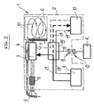
Figure 2 is a block diagram of a connection between a motor unit, battery means and auxiliary power supply means of the vacuum cleaner inFigure 1 ; -
Figure 3 is a quality diagram of the pattern of three possible operating speeds of the motor unit inFigure 2 in which the Y-axis shows the number of rpm of the motor unit and the x-axis shows the operating time; -
Figure 4 is a quality diagram of the charge conditions of the auxiliary power supply means inFigure 2 in which the Y-axis shows the charge levels of auxiliary power supply means and the X-axis shows their charging and discharging times. -
Figure 5 is a quality diagram of the charge conditions of the battery means inFigure 2 in which the Y-axis shows the charge levels of battery means and the X-axis shows their discharging times. - With special reference to the
Figure 1 , a portable household appliance without power cable, has been schematically designated byreference number 1. - The
vacuum cleaner 1 comprises anexternal casing 2 which contains, inside it, amotor unit 3 that drives afan 4 rotatably, so as to create air suction from outside through asuction pipe 5. - The suctioned air enters a chamber 6, wherein it grows into rotary flows, as indicated by the arrows F1, so the debris in the suctioned air is released by centrifugal or gravity force and collected up on the bottom of the chamber 6.
- The air then passes through a first filter 7 and laps the
motor unit 3 to cool it; it is then conveyed outside after passing through a second filter 8. - The
motor unit 3 is constantly supplied by arechargeable battery 9; besides thisbattery 9, a set of ultra-capacitors 10 is also fitted that represent auxiliary power supply means for supplying themotor unit 3 and which can be actuated for time intervals, as described below. - Through a first electric
power connection line 17, thebattery 9 supplies themotor unit 3 and, through a second electricpower connection line 18, also the ultra-capacitors 10 when these are not used, to keep them charged and ready to provide power whenever this is required. - As is known, the ultra-capacitors 10 are power accumulators that discharge at very limited time intervals and provide most of the stored power, and which recharge in an equally limited amount of time, meaning in just a few seconds; these ultra-capacitors are made, for example, by the US company. Maxwell Technologies Inc. and have different charge capacities for each type of use.
- The
battery 9 can be recharged by means of a normal electric power mains, such as, for example, a domestic or industrial power mains, indicated by "R". - According to the invention, and with reference to the
Figures 1 and2 , it can be observed that the recharge of both thebattery 9 and the ultra-capacitors 10 is by induction, by means of abase 11 which is connected to an electric power point and which has atransmitter unit 12 that produces magnetic waves and which is started or stopped by means of the first electronic means, for example a programmableelectronic board 16. - The
vacuum cleaner 1 also comprises, inside thecasing 2, areceiver unit 13, arranged to receive the recharge electric waves transmitted by thetransmitter unit 12 and send these to thebattery 9 and to the ultra-capacitors 10, through a thirdelectric power line 19, when thevacuum cleaner 1 is positioned on thebase 11, and specifically in aplacement seat 14 obtained in the latter, shaped so that, in a recharge position of thevacuum cleaner 1, thetransmitter unit 12 and thereceiver unit 13 are mutually positioned in relation to one another. - The
battery 9, when charged, supplies themotor unit 3 in a substantially constant way during the latter's operation. - The
motor unit 3 can run at different operating speeds which, in the case shown infigures 3, 4, 5 , are, for example, three in total, i.e. a minimum speed "M", a medium speed "MD", and a top speed "MX". - Naturally, the number of operating speeds can also be restricted to two or be more than three.
- The user can select the most suitable speed for his/her operating requirements using the conventional control located, for example, on the
vacuum cleaner 1. - Every time the user changes the operating speed of the
motor unit 3, and increases this, besides the constant power supplied by thebattery 9, an auxiliary supply is provided actuated by a programmedelectronic board 15 that actuates the ultra-capacitors 10 so these supply themotor unit 3 for a first time interval T1 needed to switch from a lower operating speed, for example a minimum speed "M" to a higher operating speed, for example a medium speed "MD", or also from a medium speed "MD" to a top speed "MX". - More in detail, with reference to
figure 3 , the tilted segment R1 indicates an ignition phase of themotor unit 3, which switches from zero operating speed, to minimum operating speed, indicated on the Y-axis by the letter "M". - During this switch, the motor unit is supplied jointly both by the
battery 9 and by the ultra-capacitors 10 actuated by theelectronic board 15, which as it is shown on the corresponding diagram ofFigure 4 , undergo a quick reduction in overall possessed charge, as qualitatively indicated by the tilted segment U1, until they are disengaged by theelectronic board 15 and their power supply is interrupted, when themotor unit 3 has reached the minimum operating speed "M". - Again with reference to the diagram in
Figure 3 , the horizontal segment R2 shows a minimum operating speed condition of themotor unit 3 for a time interval FZ 1 set by the user, who uses thevacuum cleaner 1 at this operating speed. - During this time interval FZ1, the ultra-capacitors 10 are quickly recharged by the
battery 9, as indicated by segment U2 in the diagram ofFigure 4 , through the furtherelectric power line 17, and then kept charged as indicated by horizontal segment U3 of the sameFigure 4 for the entire time interval FZ1. - During this phase, the
battery 9 gradually loses a quantity of its charge, as indicated in the diagram ofFigure 5 by segments B1 and B2, due to the continual use by the user of thevacuum cleaner 1. - When the user requires a higher operating speed of the
motor unit 3, i.e. an increase in the suction force of thevacuum cleaner 1, he/she operates a special control provided for the purpose on thevacuum cleaner 1, and not shown inasmuch known to the technician skilled in the field. - The
electronic board 15 receives the user's request and actuates the ultra-capacitors 10 for a first time interval T1 so as to supply themotor unit 3 together with thebattery 9 during this time interval required by themotor unit 3 to switch from the minimum operating speed "M" to a higher operating speed, for example, medium speed indicated by "MD" on the diagram ofFigure 3 . - When this medium operating speed "MD" is reached, as shown on the diagram of
Figure 3 by the inclined segment "R3", theelectronic board 15 disengages the ultra-capacitors 10 which, meanwhile, have again undergone a drop in charge, as shown on the diagram ofFigure 4 by segment U4; thebattery 9 also undergoes a further drop in charge as shown by segment B3 on the diagram ofFigure 5 . - The user can maintain the medium operating speed for a time interval indicated by "FZ2" in
Figures 3, 4, 5 : in detail, this condition is shown by horizontal segment R4 on the diagram ofFigure 3 , during which thebattery 9 undergoes a further drop in charge indicated by segment B4 infigure 5 , while the ultra-capacitors 10 are quickly recharged by thebattery 9 in a time interval of about 2/3 seconds, as indicated by the segment U5 ofFigure 4 , even though they do not reach maximum charge level. - If the user requires a further increase in the operating speed of the
motor unit 3 up to a maximum speed, indicated in the diagram ofFigure 3 by "MX", theelectronic board 15 again actuates the ultra-capacitors 10 for a further first time interval T1, and keeps these actuated until themotor unit 3 has reached the maximum required operating speed "MX". - This increase in operating speed is indicated in the diagram of
Figure 3 by the segment R5, while by the segment R6 is indicated a subsequent constant operating speed of themotor unit 3 at maximum power. - In the ultra-capacitors 10 and in the battery 8, the same conditions occur, qualitatively indicated previously, for switching from a minimum operating speed "M" to a medium operating speed "MD", i.e., again with reference to the diagram of
Figure 4 , it can be observed that the ultra-capacitors 10 at constant operating speed R4 maintain their charge, as indicated by segment U6 while, at the subsequent further first time interval T1, they undergo a quick reduction in charge, qualitatively indicated by segment U7, being actuated by theelectronic board 15 to supply themotor unit 3 during the change in operating speed. - The
battery 9, in these conditions, continues to undergo a drop in overall charge, indicated by segments B5 and B6 respectively. - When the user stops using the
vacuum cleaner 1 and, by means of the control, again switches the operating speed of themotor unit 3 to minimum speed "M", themagnetic board 15 switches the operation of themotor unit 3 so the inertia this possesses due to the operating speed, is converted, during the switch to a lower operating speed, into energy used to recharge, during a second short time interval T2, at least the ultra-capacitors 10 to allow an albeit short extension of the operation of themotor unit 3 at a lower speed, extend the operation of thevacuum cleaner 1 and complete the vacuum operation to be performed. - Practically speaking, in the diagram of
Figure 3 , the segment R7 indicates the gradual reduction in the operation speed of the vacuum cleaner during a second time interval T2, while the vertical segment R8 indicates that as soon as the user uses the control to reduce the operating speed of themotor unit 3, this no longer absorbs power, but on the contrary, generates it. - The ultra-capacitors 10 are recharged during a third operation time interval FZ3, as shown by segment U8 in the diagram of
Figure 4 and maintain the charge level reached, as shown by the next horizontal segment U9. - When the
motor unit 3 switches to power generator in the second time interval T2, the ultra-capacitors 10 are recharged by this in a substantially complete way, as indicated by segment U10 and make it possible to continue operating themotor unit 3 for some tens of seconds more. - As the diagram in
Figure 5 shows, during the same second time interval T2 thebattery 9 also receives a small charge increase, shown by the segment B7. - When both the ultra-capacitors 10 and the
battery 9 are down, a condition indicated by the segments U11 infigure 4 and B8 inFigure 5 respectively, the user positions thevacuum cleaner 1 in thehousing 14 of thebase 11 and, by means of thetransmitter unit 12 and thereceiver unit 13, both thebattery 9 and the ultra-capacitors 10 are recharged. - It should be noted that the charge times of the ultra-capacitors 10 are very short, just a few seconds, and the user can also decide to recharge, according to a quick charging condition, only the latter by placing the
vacuum cleaner 1 on thebase 11 and removing this off the base once the ultra-capacitors 10 are fully recharged; this way, the user can continue using thevacuum cleaner 1 for a short time, but without having to wait for thebattery 9 to also fully recharge. - The user can repeat this quick recharged condition several times to prolong the operation of the
vacuum cleaner 1 only by means of the ultra-capacitors 10. - The use of the latter therefore not only makes it possible to extend the operating time of the
vacuum cleaner 1, or any other portable household appliance on which they can be fitted together with abattery 9, but also to reduce the capacity of thebattery 9, and therefore the weight and the cost of the latter, because during the switch from lower to higher operating speed, the increase in the power supply required to increase these rotating speeds is provided by the ultra-capacitors 10 which add their power, for a time interval controlled by theelectronic board 15, to the constant power supply provided by thebattery 9.
Claims (11)
- Portable household appliance comprising: a motor unit (3) arranged to operate at least at lower operating speeds (M) or at higher speeds (MD, MX) and vice versa; first power supply means (9) designed to constantly supply said motor unit (3); control means (15) for increasing said lower speeds (M) in a first time interval (T1) up to said higher speeds (MD, MX) or for reducing said higher speeds (MD, MX) in a second time interval (T2) up to said lower speeds (M) said appliance further comprises auxiliary power supply means (10) for the temporary power supply of said motor unit (3) which can be actuated during said first time interval (T1), wherein said motor unit (3) is arranged to recharge at least said auxillary power supply means (10) in said second time interval (T2), characterized in that said control means (15) are also arranged to switch said motor unit (3) to a recharge generator unit so to recharge said auxiliary power supply means (10) in said second time interval (T2).
- Portable household appliance according to claim 1, wherein said first power supply means comprise a battery (9).
- Portable household appliance according to claim 2, wherein said battery (9) is of the rechargeable type by power recharging means (R, 11, 12, 13).
- Portable household appliance according to claim 3, wherein said power recharging means comprises recharging means (12, 13) by induction.
- Portable household appliance according to claim 4, wherein said recharging means (12, 13) by induction comprises: base means (11) which shapes a placement seat (14) of said household appliance (1) under a recharge condition of said battery (9) and/or of said auxiliary power supply means (10); recharge power transmitter means (12), housed in said base means (11) and which can be connected to a conventional electric energy mains supply (R); first electronic means (16) arranged to automatically actuate said transmitter means (12) when said household appliance (1) is positioned in said placement seat (14); recharge receiver means (13) housed in said portable household appliance and connected to said battery (9) and said auxiliary power supply means (10).
- Portable household appliance according to claim 5, wherein said placement seat (14) is shaped to receive said household appliance (1) in a pre-established position so that said transmitter means (12) and said recharge receiver means (13) are facing each other.
- Portable household appliance according to claim 1, wherein said auxiliary power supply means (10) comprise at least one ultra-capacitor (10) connected to said motor unit (3) and to said battery (9) through connection circuits (17, 19).
- Portable household appliance according to any of claims 2 to 6, wherein said auxiliary power supply means (10) comprise at least one ultra-capacitor (10) and wherein said control means (15) are provided for to be placed between said at least one ultra-capacitor (10) and said battery (9) and arranged to actuate and/or stop said at least one ultra-capacitor (10) in each said first time interval (T1).
- Portable household appliance according to any of claims 5 or 6, wherein said auxiliary power supply means (10) comprise at least one ultra-capacitor (10), wherein said at least one ultra-capacitor (10) is rechargeable one or more times with said base means (11) and separately from said battery (9).
- Portable household appliance according to any of claims 2 to 9, wherein said auxiliary power supply means (10) comprise at least one ultra-capacitor (10), wherein said at least one ultra-capacitor (10) is suitable to supply said motor unit (3) separately from said battery (9).
- Portable household appliance according to any of the preceding claims, wherein said portable household appliance comprises a vacuum cleaner (1).
Applications Claiming Priority (2)
| Application Number | Priority Date | Filing Date | Title |
|---|---|---|---|
| IT000321A ITMO20050321A1 (en) | 2005-11-29 | 2005-11-29 | PORTABLE APPLIANCES |
| PCT/IB2006/003230 WO2007063377A2 (en) | 2005-11-29 | 2006-11-16 | Portable household appliance |
Publications (2)
| Publication Number | Publication Date |
|---|---|
| EP1962662A2 EP1962662A2 (en) | 2008-09-03 |
| EP1962662B1 true EP1962662B1 (en) | 2011-02-09 |
Family
ID=38092614
Family Applications (1)
| Application Number | Title | Priority Date | Filing Date |
|---|---|---|---|
| EP06831572A Not-in-force EP1962662B1 (en) | 2005-11-29 | 2006-11-16 | Portable household appliance |
Country Status (7)
| Country | Link |
|---|---|
| US (1) | US7950107B2 (en) |
| EP (1) | EP1962662B1 (en) |
| CN (1) | CN101316543B (en) |
| AT (1) | ATE497715T1 (en) |
| DE (1) | DE602006020067D1 (en) |
| IT (1) | ITMO20050321A1 (en) |
| WO (1) | WO2007063377A2 (en) |
Families Citing this family (10)
| Publication number | Priority date | Publication date | Assignee | Title |
|---|---|---|---|---|
| US8601640B2 (en) * | 2005-12-19 | 2013-12-10 | Miele & Cie. Kg | Vacuum cleaner, especially floor vacuum cleaner |
| US11857142B2 (en) | 2006-12-15 | 2024-01-02 | Omachron Intellectual Property Inc. | Surface cleaning apparatus having an energy storage member and a charger for an energy storage member |
| WO2009121532A1 (en) * | 2008-04-02 | 2009-10-08 | Miele & Cie. Kg | Electric device having an electric motor and storage battery pack |
| CN105744873B (en) * | 2013-11-22 | 2018-09-04 | 创科实业有限公司 | Battery powered wireless cleaning systems |
| EP3313252B1 (en) * | 2015-06-24 | 2021-03-03 | AB Electrolux | Vacuum cleaner system |
| US11246465B2 (en) * | 2019-02-20 | 2022-02-15 | Omachron Intellectual Property Inc. | Surface cleaning apparatus having an energy storage member and a charger for an energy storage member |
| GB2595178B (en) * | 2019-02-20 | 2022-12-07 | Omachron Intellectual Property Inc | Surface cleaning apparatus having an energy storage member and a charger for an energy storage member |
| US11229333B2 (en) * | 2019-02-20 | 2022-01-25 | Omachron Intellectual Property Inc. | Surface cleaning apparatus having an energy storage member and a charger for an energy storage member |
| US11218017B2 (en) | 2019-02-21 | 2022-01-04 | Omachron Intellectual Property Inc. | Cordless appliance, such as a surface cleaning apparatus, and a charging unit therefor |
| US11190043B2 (en) | 2019-02-21 | 2021-11-30 | Omachron Intellectual Property Inc. | Cordless appliance, such as a surface cleaning apparatus, and a charging unit therefor |
Family Cites Families (18)
| Publication number | Priority date | Publication date | Assignee | Title |
|---|---|---|---|---|
| US2002A (en) * | 1841-03-12 | Tor and planter for plowing | ||
| US3695006A (en) * | 1970-10-23 | 1972-10-03 | Dynamics Corp America | Vacuum cleaner |
| US4005502A (en) * | 1975-09-25 | 1977-02-01 | Stevens Boyer Elaine | Electric power scrubber |
| US4731898A (en) | 1986-09-05 | 1988-03-22 | Royal Appliance Mfg. Co. | Brush speed indicator |
| SE461249B (en) | 1988-06-06 | 1990-01-29 | Electrolux Ab | BATTERY FITTED BOOSTER FUNCTION APPLIANCE |
| GB2225219B (en) | 1988-10-19 | 1992-08-26 | Hoover Plc | Suction cleaner |
| SE463070B (en) * | 1989-02-14 | 1990-10-08 | Electrolux Ab | DEVICE BY A LIFT CLEANER |
| BE1008470A3 (en) * | 1994-07-04 | 1996-05-07 | Colens Andre | Device and automatic system and equipment dedusting sol y adapted. |
| US5926909A (en) * | 1996-08-28 | 1999-07-27 | Mcgee; Daniel | Remote control vacuum cleaner and charging system |
| WO2000077918A1 (en) | 1999-06-11 | 2000-12-21 | Pri Automation, Inc. | Ultracapacitor power supply for an electric vehicle |
| CN2409894Y (en) * | 1999-11-17 | 2000-12-13 | 谢明毅 | Isolating impedance-changing speed regulator for suction cleaner |
| KR20020087100A (en) * | 2000-03-22 | 2002-11-21 | 더 보오드 오브 트러스티스 오브 더 유니버시티 오브 일리노이즈 | Ultra-capacitor based dynamically regulated charge pump power converter |
| US6457205B1 (en) * | 2000-05-24 | 2002-10-01 | Fantom Technologies Inc. | Vacuum cleaner having a plurality of power modes |
| AU767561B2 (en) | 2001-04-18 | 2003-11-13 | Samsung Kwangju Electronics Co., Ltd. | Robot cleaner, system employing the same and method for reconnecting to external recharging device |
| TW579289B (en) * | 2001-05-23 | 2004-03-11 | Toshiba Tec Kk | Vacuum cleaner |
| CN2503834Y (en) * | 2001-09-26 | 2002-08-07 | 苏州工业园区天诚网络技术有限公司 | Cordless duster |
| JP2005013460A (en) * | 2003-06-26 | 2005-01-20 | Matsushita Electric Ind Co Ltd | Rechargeable vacuum cleaner |
| US20060076035A1 (en) * | 2004-10-08 | 2006-04-13 | Mcgee Brian | Surface cleaning apparatus |
-
2005
- 2005-11-29 IT IT000321A patent/ITMO20050321A1/en unknown
-
2006
- 2006-11-16 CN CN2006800447678A patent/CN101316543B/en not_active Expired - Fee Related
- 2006-11-16 DE DE602006020067T patent/DE602006020067D1/en active Active
- 2006-11-16 AT AT06831572T patent/ATE497715T1/en not_active IP Right Cessation
- 2006-11-16 EP EP06831572A patent/EP1962662B1/en not_active Not-in-force
- 2006-11-16 US US12/085,320 patent/US7950107B2/en not_active Expired - Fee Related
- 2006-11-16 WO PCT/IB2006/003230 patent/WO2007063377A2/en active Application Filing
Also Published As
| Publication number | Publication date |
|---|---|
| WO2007063377A3 (en) | 2007-11-15 |
| ATE497715T1 (en) | 2011-02-15 |
| WO2007063377A2 (en) | 2007-06-07 |
| EP1962662A2 (en) | 2008-09-03 |
| US7950107B2 (en) | 2011-05-31 |
| US20090151114A1 (en) | 2009-06-18 |
| DE602006020067D1 (en) | 2011-03-24 |
| CN101316543B (en) | 2010-06-16 |
| ITMO20050321A1 (en) | 2007-05-30 |
| CN101316543A (en) | 2008-12-03 |
Similar Documents
| Publication | Publication Date | Title |
|---|---|---|
| EP1962662B1 (en) | Portable household appliance | |
| US20210359526A1 (en) | Series-connected battery packs, system and method | |
| US8732896B2 (en) | Hybrid electric cleaning device | |
| US6526622B2 (en) | Vacuum cleaner actuated by reconfiguration of the vacuum cleaner | |
| EP3551389A1 (en) | Power tool and light unit | |
| CN209408223U (en) | Milling tools | |
| CN101262804A (en) | Hybrid vacuum cleaner nozzle | |
| EP1501400A1 (en) | Method for operating an appliance that uses the method | |
| CN103629125A (en) | Rechargeable fan device | |
| JP2017109049A (en) | Dust collector | |
| CN105435917A (en) | Food waste disposer and control method thereof | |
| EP4007114A1 (en) | Method for operation of an electronic device equipped with two or more battery packs and respective electronic device | |
| US20160256027A1 (en) | Constant Voltage Circuit Module with A Voltage Compensating Unit to Perform Stepless Speed Regulation on a Motor | |
| CN112438656B (en) | Electric dust collector | |
| CN205413230U (en) | Food rubbish processor | |
| CN112292795A (en) | Charging type dust collector | |
| JP3915764B2 (en) | Electric vacuum cleaner | |
| CN211505311U (en) | Water inlet detection circuit and driving circuit of pool sweeper | |
| JP3599014B2 (en) | Battery discharge control means and vacuum cleaner using the same | |
| KR102561158B1 (en) | Hybrid battery powered cleaning vehicle | |
| CN2537338Y (en) | Cableless DC electric vacuum cleaner | |
| JP2004113595A (en) | Vacuum cleaner | |
| WO2020100557A1 (en) | Battery pack and electrical device employing same | |
| CN116138667A (en) | Power supply method of surface cleaning device | |
| JP2021020011A (en) | Vacuum cleaner |
Legal Events
| Date | Code | Title | Description |
|---|---|---|---|
| PUAI | Public reference made under article 153(3) epc to a published international application that has entered the european phase |
Free format text: ORIGINAL CODE: 0009012 |
|
| 17P | Request for examination filed |
Effective date: 20080619 |
|
| AK | Designated contracting states |
Kind code of ref document: A2 Designated state(s): AT BE BG CH CY CZ DE DK EE ES FI FR GB GR HU IE IS IT LI LT LU LV MC NL PL PT RO SE SI SK TR |
|
| GRAP | Despatch of communication of intention to grant a patent |
Free format text: ORIGINAL CODE: EPIDOSNIGR1 |
|
| DAX | Request for extension of the european patent (deleted) | ||
| GRAS | Grant fee paid |
Free format text: ORIGINAL CODE: EPIDOSNIGR3 |
|
| GRAA | (expected) grant |
Free format text: ORIGINAL CODE: 0009210 |
|
| AK | Designated contracting states |
Kind code of ref document: B1 Designated state(s): AT BE BG CH CY CZ DE DK EE ES FI FR GB GR HU IE IS IT LI LT LU LV MC NL PL PT RO SE SI SK TR |
|
| REG | Reference to a national code |
Ref country code: GB Ref legal event code: FG4D |
|
| REG | Reference to a national code |
Ref country code: CH Ref legal event code: EP |
|
| REG | Reference to a national code |
Ref country code: IE Ref legal event code: FG4D |
|
| REF | Corresponds to: |
Ref document number: 602006020067 Country of ref document: DE Date of ref document: 20110324 Kind code of ref document: P |
|
| REG | Reference to a national code |
Ref country code: DE Ref legal event code: R096 Ref document number: 602006020067 Country of ref document: DE Effective date: 20110324 |
|
| REG | Reference to a national code |
Ref country code: NL Ref legal event code: VDEP Effective date: 20110209 |
|
| LTIE | Lt: invalidation of european patent or patent extension |
Effective date: 20110209 |
|
| PG25 | Lapsed in a contracting state [announced via postgrant information from national office to epo] |
Ref country code: ES Free format text: LAPSE BECAUSE OF FAILURE TO SUBMIT A TRANSLATION OF THE DESCRIPTION OR TO PAY THE FEE WITHIN THE PRESCRIBED TIME-LIMIT Effective date: 20110520 Ref country code: GR Free format text: LAPSE BECAUSE OF FAILURE TO SUBMIT A TRANSLATION OF THE DESCRIPTION OR TO PAY THE FEE WITHIN THE PRESCRIBED TIME-LIMIT Effective date: 20110510 Ref country code: SE Free format text: LAPSE BECAUSE OF FAILURE TO SUBMIT A TRANSLATION OF THE DESCRIPTION OR TO PAY THE FEE WITHIN THE PRESCRIBED TIME-LIMIT Effective date: 20110209 Ref country code: PT Free format text: LAPSE BECAUSE OF FAILURE TO SUBMIT A TRANSLATION OF THE DESCRIPTION OR TO PAY THE FEE WITHIN THE PRESCRIBED TIME-LIMIT Effective date: 20110609 Ref country code: LV Free format text: LAPSE BECAUSE OF FAILURE TO SUBMIT A TRANSLATION OF THE DESCRIPTION OR TO PAY THE FEE WITHIN THE PRESCRIBED TIME-LIMIT Effective date: 20110209 Ref country code: LT Free format text: LAPSE BECAUSE OF FAILURE TO SUBMIT A TRANSLATION OF THE DESCRIPTION OR TO PAY THE FEE WITHIN THE PRESCRIBED TIME-LIMIT Effective date: 20110209 |
|
| PG25 | Lapsed in a contracting state [announced via postgrant information from national office to epo] |
Ref country code: NL Free format text: LAPSE BECAUSE OF FAILURE TO SUBMIT A TRANSLATION OF THE DESCRIPTION OR TO PAY THE FEE WITHIN THE PRESCRIBED TIME-LIMIT Effective date: 20110209 Ref country code: SI Free format text: LAPSE BECAUSE OF FAILURE TO SUBMIT A TRANSLATION OF THE DESCRIPTION OR TO PAY THE FEE WITHIN THE PRESCRIBED TIME-LIMIT Effective date: 20110209 Ref country code: CY Free format text: LAPSE BECAUSE OF FAILURE TO SUBMIT A TRANSLATION OF THE DESCRIPTION OR TO PAY THE FEE WITHIN THE PRESCRIBED TIME-LIMIT Effective date: 20110209 Ref country code: FI Free format text: LAPSE BECAUSE OF FAILURE TO SUBMIT A TRANSLATION OF THE DESCRIPTION OR TO PAY THE FEE WITHIN THE PRESCRIBED TIME-LIMIT Effective date: 20110209 Ref country code: PL Free format text: LAPSE BECAUSE OF FAILURE TO SUBMIT A TRANSLATION OF THE DESCRIPTION OR TO PAY THE FEE WITHIN THE PRESCRIBED TIME-LIMIT Effective date: 20110209 Ref country code: BG Free format text: LAPSE BECAUSE OF FAILURE TO SUBMIT A TRANSLATION OF THE DESCRIPTION OR TO PAY THE FEE WITHIN THE PRESCRIBED TIME-LIMIT Effective date: 20110509 Ref country code: AT Free format text: LAPSE BECAUSE OF FAILURE TO SUBMIT A TRANSLATION OF THE DESCRIPTION OR TO PAY THE FEE WITHIN THE PRESCRIBED TIME-LIMIT Effective date: 20110209 Ref country code: BE Free format text: LAPSE BECAUSE OF FAILURE TO SUBMIT A TRANSLATION OF THE DESCRIPTION OR TO PAY THE FEE WITHIN THE PRESCRIBED TIME-LIMIT Effective date: 20110209 |
|
| PG25 | Lapsed in a contracting state [announced via postgrant information from national office to epo] |
Ref country code: EE Free format text: LAPSE BECAUSE OF FAILURE TO SUBMIT A TRANSLATION OF THE DESCRIPTION OR TO PAY THE FEE WITHIN THE PRESCRIBED TIME-LIMIT Effective date: 20110209 Ref country code: DK Free format text: LAPSE BECAUSE OF FAILURE TO SUBMIT A TRANSLATION OF THE DESCRIPTION OR TO PAY THE FEE WITHIN THE PRESCRIBED TIME-LIMIT Effective date: 20110209 |
|
| PG25 | Lapsed in a contracting state [announced via postgrant information from national office to epo] |
Ref country code: SK Free format text: LAPSE BECAUSE OF FAILURE TO SUBMIT A TRANSLATION OF THE DESCRIPTION OR TO PAY THE FEE WITHIN THE PRESCRIBED TIME-LIMIT Effective date: 20110209 Ref country code: RO Free format text: LAPSE BECAUSE OF FAILURE TO SUBMIT A TRANSLATION OF THE DESCRIPTION OR TO PAY THE FEE WITHIN THE PRESCRIBED TIME-LIMIT Effective date: 20110209 Ref country code: CZ Free format text: LAPSE BECAUSE OF FAILURE TO SUBMIT A TRANSLATION OF THE DESCRIPTION OR TO PAY THE FEE WITHIN THE PRESCRIBED TIME-LIMIT Effective date: 20110209 |
|
| PLBE | No opposition filed within time limit |
Free format text: ORIGINAL CODE: 0009261 |
|
| STAA | Information on the status of an ep patent application or granted ep patent |
Free format text: STATUS: NO OPPOSITION FILED WITHIN TIME LIMIT |
|
| 26N | No opposition filed |
Effective date: 20111110 |
|
| REG | Reference to a national code |
Ref country code: DE Ref legal event code: R097 Ref document number: 602006020067 Country of ref document: DE Effective date: 20111110 |
|
| PG25 | Lapsed in a contracting state [announced via postgrant information from national office to epo] |
Ref country code: MC Free format text: LAPSE BECAUSE OF NON-PAYMENT OF DUE FEES Effective date: 20111130 |
|
| REG | Reference to a national code |
Ref country code: CH Ref legal event code: PL |
|
| PG25 | Lapsed in a contracting state [announced via postgrant information from national office to epo] |
Ref country code: CH Free format text: LAPSE BECAUSE OF NON-PAYMENT OF DUE FEES Effective date: 20111130 Ref country code: LI Free format text: LAPSE BECAUSE OF NON-PAYMENT OF DUE FEES Effective date: 20111130 |
|
| REG | Reference to a national code |
Ref country code: IE Ref legal event code: MM4A |
|
| PG25 | Lapsed in a contracting state [announced via postgrant information from national office to epo] |
Ref country code: IE Free format text: LAPSE BECAUSE OF NON-PAYMENT OF DUE FEES Effective date: 20111116 |
|
| PG25 | Lapsed in a contracting state [announced via postgrant information from national office to epo] |
Ref country code: LU Free format text: LAPSE BECAUSE OF NON-PAYMENT OF DUE FEES Effective date: 20111116 |
|
| PG25 | Lapsed in a contracting state [announced via postgrant information from national office to epo] |
Ref country code: IS Free format text: LAPSE BECAUSE OF FAILURE TO SUBMIT A TRANSLATION OF THE DESCRIPTION OR TO PAY THE FEE WITHIN THE PRESCRIBED TIME-LIMIT Effective date: 20110209 |
|
| PG25 | Lapsed in a contracting state [announced via postgrant information from national office to epo] |
Ref country code: TR Free format text: LAPSE BECAUSE OF FAILURE TO SUBMIT A TRANSLATION OF THE DESCRIPTION OR TO PAY THE FEE WITHIN THE PRESCRIBED TIME-LIMIT Effective date: 20110209 |
|
| PG25 | Lapsed in a contracting state [announced via postgrant information from national office to epo] |
Ref country code: HU Free format text: LAPSE BECAUSE OF FAILURE TO SUBMIT A TRANSLATION OF THE DESCRIPTION OR TO PAY THE FEE WITHIN THE PRESCRIBED TIME-LIMIT Effective date: 20110209 |
|
| REG | Reference to a national code |
Ref country code: FR Ref legal event code: PLFP Year of fee payment: 10 |
|
| REG | Reference to a national code |
Ref country code: DE Ref legal event code: R082 Ref document number: 602006020067 Country of ref document: DE Representative=s name: WUNDERLICH & HEIM PATENTANWAELTE PARTNERSCHAFT, DE Ref country code: DE Ref legal event code: R082 Ref document number: 602006020067 Country of ref document: DE Representative=s name: WEBER & HEIM PATENTANWAELTE PARTNERSCHAFTSGESE, DE Ref country code: DE Ref legal event code: R081 Ref document number: 602006020067 Country of ref document: DE Owner name: ROSCHI, CATIA, GALLIATE LOMBARDO, IT Free format text: FORMER OWNER: KOSTEC SA, CHIASSO, CH Ref country code: DE Ref legal event code: R081 Ref document number: 602006020067 Country of ref document: DE Owner name: ROSCHI, RICCARDO, IT Free format text: FORMER OWNER: KOSTEC SA, CHIASSO, CH |
|
| REG | Reference to a national code |
Ref country code: GB Ref legal event code: 732E Free format text: REGISTERED BETWEEN 20160929 AND 20161004 |
|
| REG | Reference to a national code |
Ref country code: FR Ref legal event code: TQ Owner name: RICCARDO ROSCHI, IT Effective date: 20161017 Ref country code: FR Ref legal event code: TQ Owner name: CATIA ROSCHI, IT Effective date: 20161017 Ref country code: FR Ref legal event code: PLFP Year of fee payment: 11 |
|
| REG | Reference to a national code |
Ref country code: FR Ref legal event code: PLFP Year of fee payment: 12 |
|
| PGFP | Annual fee paid to national office [announced via postgrant information from national office to epo] |
Ref country code: DE Payment date: 20181120 Year of fee payment: 13 |
|
| PGFP | Annual fee paid to national office [announced via postgrant information from national office to epo] |
Ref country code: GB Payment date: 20181120 Year of fee payment: 13 Ref country code: IT Payment date: 20181120 Year of fee payment: 13 Ref country code: FR Payment date: 20181123 Year of fee payment: 13 |
|
| REG | Reference to a national code |
Ref country code: DE Ref legal event code: R082 Ref document number: 602006020067 Country of ref document: DE Representative=s name: WUNDERLICH & HEIM PATENTANWAELTE PARTNERSCHAFT, DE |
|
| REG | Reference to a national code |
Ref country code: DE Ref legal event code: R119 Ref document number: 602006020067 Country of ref document: DE |
|
| GBPC | Gb: european patent ceased through non-payment of renewal fee |
Effective date: 20191116 |
|
| PG25 | Lapsed in a contracting state [announced via postgrant information from national office to epo] |
Ref country code: FR Free format text: LAPSE BECAUSE OF NON-PAYMENT OF DUE FEES Effective date: 20191130 Ref country code: DE Free format text: LAPSE BECAUSE OF NON-PAYMENT OF DUE FEES Effective date: 20200603 Ref country code: GB Free format text: LAPSE BECAUSE OF NON-PAYMENT OF DUE FEES Effective date: 20191116 Ref country code: IT Free format text: LAPSE BECAUSE OF NON-PAYMENT OF DUE FEES Effective date: 20191116 |