EP1962266A1 - Organic light emitting diode display device and driving method thereof - Google Patents
Organic light emitting diode display device and driving method thereof Download PDFInfo
- Publication number
- EP1962266A1 EP1962266A1 EP08151743A EP08151743A EP1962266A1 EP 1962266 A1 EP1962266 A1 EP 1962266A1 EP 08151743 A EP08151743 A EP 08151743A EP 08151743 A EP08151743 A EP 08151743A EP 1962266 A1 EP1962266 A1 EP 1962266A1
- Authority
- EP
- European Patent Office
- Prior art keywords
- data
- input image
- image data
- saturation
- ssel
- Prior art date
- Legal status (The legal status is an assumption and is not a legal conclusion. Google has not performed a legal analysis and makes no representation as to the accuracy of the status listed.)
- Granted
Links
Images


Classifications
-
- G—PHYSICS
- G09—EDUCATION; CRYPTOGRAPHY; DISPLAY; ADVERTISING; SEALS
- G09G—ARRANGEMENTS OR CIRCUITS FOR CONTROL OF INDICATING DEVICES USING STATIC MEANS TO PRESENT VARIABLE INFORMATION
- G09G3/00—Control arrangements or circuits, of interest only in connection with visual indicators other than cathode-ray tubes
- G09G3/20—Control arrangements or circuits, of interest only in connection with visual indicators other than cathode-ray tubes for presentation of an assembly of a number of characters, e.g. a page, by composing the assembly by combination of individual elements arranged in a matrix no fixed position being assigned to or needed to be assigned to the individual characters or partial characters
- G09G3/22—Control arrangements or circuits, of interest only in connection with visual indicators other than cathode-ray tubes for presentation of an assembly of a number of characters, e.g. a page, by composing the assembly by combination of individual elements arranged in a matrix no fixed position being assigned to or needed to be assigned to the individual characters or partial characters using controlled light sources
- G09G3/30—Control arrangements or circuits, of interest only in connection with visual indicators other than cathode-ray tubes for presentation of an assembly of a number of characters, e.g. a page, by composing the assembly by combination of individual elements arranged in a matrix no fixed position being assigned to or needed to be assigned to the individual characters or partial characters using controlled light sources using electroluminescent panels
-
- G—PHYSICS
- G09—EDUCATION; CRYPTOGRAPHY; DISPLAY; ADVERTISING; SEALS
- G09G—ARRANGEMENTS OR CIRCUITS FOR CONTROL OF INDICATING DEVICES USING STATIC MEANS TO PRESENT VARIABLE INFORMATION
- G09G3/00—Control arrangements or circuits, of interest only in connection with visual indicators other than cathode-ray tubes
- G09G3/20—Control arrangements or circuits, of interest only in connection with visual indicators other than cathode-ray tubes for presentation of an assembly of a number of characters, e.g. a page, by composing the assembly by combination of individual elements arranged in a matrix no fixed position being assigned to or needed to be assigned to the individual characters or partial characters
- G09G3/2003—Display of colours
-
- G—PHYSICS
- G01—MEASURING; TESTING
- G01J—MEASUREMENT OF INTENSITY, VELOCITY, SPECTRAL CONTENT, POLARISATION, PHASE OR PULSE CHARACTERISTICS OF INFRARED, VISIBLE OR ULTRAVIOLET LIGHT; COLORIMETRY; RADIATION PYROMETRY
- G01J1/00—Photometry, e.g. photographic exposure meter
- G01J1/38—Photometry, e.g. photographic exposure meter using wholly visual means
- G01J1/40—Photometry, e.g. photographic exposure meter using wholly visual means using limit or visibility or extinction effect
-
- G—PHYSICS
- G09—EDUCATION; CRYPTOGRAPHY; DISPLAY; ADVERTISING; SEALS
- G09G—ARRANGEMENTS OR CIRCUITS FOR CONTROL OF INDICATING DEVICES USING STATIC MEANS TO PRESENT VARIABLE INFORMATION
- G09G3/00—Control arrangements or circuits, of interest only in connection with visual indicators other than cathode-ray tubes
- G09G3/20—Control arrangements or circuits, of interest only in connection with visual indicators other than cathode-ray tubes for presentation of an assembly of a number of characters, e.g. a page, by composing the assembly by combination of individual elements arranged in a matrix no fixed position being assigned to or needed to be assigned to the individual characters or partial characters
-
- G—PHYSICS
- G09—EDUCATION; CRYPTOGRAPHY; DISPLAY; ADVERTISING; SEALS
- G09G—ARRANGEMENTS OR CIRCUITS FOR CONTROL OF INDICATING DEVICES USING STATIC MEANS TO PRESENT VARIABLE INFORMATION
- G09G3/00—Control arrangements or circuits, of interest only in connection with visual indicators other than cathode-ray tubes
- G09G3/20—Control arrangements or circuits, of interest only in connection with visual indicators other than cathode-ray tubes for presentation of an assembly of a number of characters, e.g. a page, by composing the assembly by combination of individual elements arranged in a matrix no fixed position being assigned to or needed to be assigned to the individual characters or partial characters
- G09G3/22—Control arrangements or circuits, of interest only in connection with visual indicators other than cathode-ray tubes for presentation of an assembly of a number of characters, e.g. a page, by composing the assembly by combination of individual elements arranged in a matrix no fixed position being assigned to or needed to be assigned to the individual characters or partial characters using controlled light sources
- G09G3/30—Control arrangements or circuits, of interest only in connection with visual indicators other than cathode-ray tubes for presentation of an assembly of a number of characters, e.g. a page, by composing the assembly by combination of individual elements arranged in a matrix no fixed position being assigned to or needed to be assigned to the individual characters or partial characters using controlled light sources using electroluminescent panels
- G09G3/32—Control arrangements or circuits, of interest only in connection with visual indicators other than cathode-ray tubes for presentation of an assembly of a number of characters, e.g. a page, by composing the assembly by combination of individual elements arranged in a matrix no fixed position being assigned to or needed to be assigned to the individual characters or partial characters using controlled light sources using electroluminescent panels semiconductive, e.g. using light-emitting diodes [LED]
-
- G—PHYSICS
- G09—EDUCATION; CRYPTOGRAPHY; DISPLAY; ADVERTISING; SEALS
- G09G—ARRANGEMENTS OR CIRCUITS FOR CONTROL OF INDICATING DEVICES USING STATIC MEANS TO PRESENT VARIABLE INFORMATION
- G09G3/00—Control arrangements or circuits, of interest only in connection with visual indicators other than cathode-ray tubes
- G09G3/20—Control arrangements or circuits, of interest only in connection with visual indicators other than cathode-ray tubes for presentation of an assembly of a number of characters, e.g. a page, by composing the assembly by combination of individual elements arranged in a matrix no fixed position being assigned to or needed to be assigned to the individual characters or partial characters
- G09G3/22—Control arrangements or circuits, of interest only in connection with visual indicators other than cathode-ray tubes for presentation of an assembly of a number of characters, e.g. a page, by composing the assembly by combination of individual elements arranged in a matrix no fixed position being assigned to or needed to be assigned to the individual characters or partial characters using controlled light sources
- G09G3/30—Control arrangements or circuits, of interest only in connection with visual indicators other than cathode-ray tubes for presentation of an assembly of a number of characters, e.g. a page, by composing the assembly by combination of individual elements arranged in a matrix no fixed position being assigned to or needed to be assigned to the individual characters or partial characters using controlled light sources using electroluminescent panels
- G09G3/32—Control arrangements or circuits, of interest only in connection with visual indicators other than cathode-ray tubes for presentation of an assembly of a number of characters, e.g. a page, by composing the assembly by combination of individual elements arranged in a matrix no fixed position being assigned to or needed to be assigned to the individual characters or partial characters using controlled light sources using electroluminescent panels semiconductive, e.g. using light-emitting diodes [LED]
- G09G3/3208—Control arrangements or circuits, of interest only in connection with visual indicators other than cathode-ray tubes for presentation of an assembly of a number of characters, e.g. a page, by composing the assembly by combination of individual elements arranged in a matrix no fixed position being assigned to or needed to be assigned to the individual characters or partial characters using controlled light sources using electroluminescent panels semiconductive, e.g. using light-emitting diodes [LED] organic, e.g. using organic light-emitting diodes [OLED]
- G09G3/3225—Control arrangements or circuits, of interest only in connection with visual indicators other than cathode-ray tubes for presentation of an assembly of a number of characters, e.g. a page, by composing the assembly by combination of individual elements arranged in a matrix no fixed position being assigned to or needed to be assigned to the individual characters or partial characters using controlled light sources using electroluminescent panels semiconductive, e.g. using light-emitting diodes [LED] organic, e.g. using organic light-emitting diodes [OLED] using an active matrix
-
- G—PHYSICS
- G09—EDUCATION; CRYPTOGRAPHY; DISPLAY; ADVERTISING; SEALS
- G09G—ARRANGEMENTS OR CIRCUITS FOR CONTROL OF INDICATING DEVICES USING STATIC MEANS TO PRESENT VARIABLE INFORMATION
- G09G2320/00—Control of display operating conditions
- G09G2320/02—Improving the quality of display appearance
- G09G2320/0242—Compensation of deficiencies in the appearance of colours
-
- G—PHYSICS
- G09—EDUCATION; CRYPTOGRAPHY; DISPLAY; ADVERTISING; SEALS
- G09G—ARRANGEMENTS OR CIRCUITS FOR CONTROL OF INDICATING DEVICES USING STATIC MEANS TO PRESENT VARIABLE INFORMATION
- G09G2320/00—Control of display operating conditions
- G09G2320/06—Adjustment of display parameters
- G09G2320/0666—Adjustment of display parameters for control of colour parameters, e.g. colour temperature
-
- G—PHYSICS
- G09—EDUCATION; CRYPTOGRAPHY; DISPLAY; ADVERTISING; SEALS
- G09G—ARRANGEMENTS OR CIRCUITS FOR CONTROL OF INDICATING DEVICES USING STATIC MEANS TO PRESENT VARIABLE INFORMATION
- G09G2360/00—Aspects of the architecture of display systems
- G09G2360/14—Detecting light within display terminals, e.g. using a single or a plurality of photosensors
- G09G2360/144—Detecting light within display terminals, e.g. using a single or a plurality of photosensors the light being ambient light
-
- G—PHYSICS
- G09—EDUCATION; CRYPTOGRAPHY; DISPLAY; ADVERTISING; SEALS
- G09G—ARRANGEMENTS OR CIRCUITS FOR CONTROL OF INDICATING DEVICES USING STATIC MEANS TO PRESENT VARIABLE INFORMATION
- G09G2360/00—Aspects of the architecture of display systems
- G09G2360/18—Use of a frame buffer in a display terminal, inclusive of the display panel
Definitions
- Exemplary embodiments relate to an organic light emitting diode (OLED) display device and driving methods thereof and, more particularly, to an OLED display device having improved display and visibility across varying ambient light conditions and driving methods thereof.
- OLED organic light emitting diode
- OLED displays Various flat display technologies, i.e., plasma display panels (PDPs), liquid crystal displays (LCDs) and OLED displays, are becoming widely used over other display devices, e.g., cathode ray tubes (CRTs), due to their small size, reduced weight and volume and energy efficiency characteristics.
- PDPs plasma display panels
- LCDs liquid crystal displays
- OLED displays may provide better luminance feature and color purity because OLED displays use an organic compound as an emitting material.
- the OLED displays may be incorporated into portable display devices, e.g., cellular phones, personal digital assistant devices, portable multimedia players and the like.
- the portable display devices may be exposed to varying light conditions, e.g., exposed to outdoor visible light, quality and visibility (or viewability) of images displayed on the portable display device may be diminished.
- quality and visibility (or viewability) of images displayed on the portable display device may be diminished.
- brightness of images displayed on the portable display device may be diminished (or faded out) under light, e.g., solar light, because surrounding or ambient light and/or illumination intensity may be brighter than the brightness of the displayed image.
- Exemplary embodiments are related to an OLED display device and driving methods thereof, which substantially overcome one or more of the problems due to the limitations and disadvantages of the related art.
- an OLED display device includes a pixel unit having a plurality of pixels connected to scan lines and data lines, a scan driver adapted to generate and supply scan signals to the scan lines, a data driver adapted to generate and supply data signals to the data lines, an optical sensor adapted to generate an optical sensor signal corresponding to an intensity of light, and a data conversion unit adapted to compare a predetermined reference value with the optical sensor signal so as to generate a selection signal for selecting one of at least three modes.
- the data conversion unit is adapted to store an input image data or a changed input image data to correspond with the selection signal.
- the data driver is adapted to generate the data signals to correspond to the input image data or the changed input image data stored in the data conversion unit.
- the data conversion unit may further include a comparator, a control unit adapted to determine changing the input image data to correspond to the selection signal, a first operator unit adapted to generate a pixel saturation data to correspond to the input image data transmitted from the control unit, a second operator unit adapted to extract the changed input image data to correspond to the pixel saturation data and the selection signal, and a memory adapted to store the input image data transmitted from the control unit or the changed input image data supplied from the second operator unit.
- a comparator adapted to determine changing the input image data to correspond to the selection signal
- a first operator unit adapted to generate a pixel saturation data to correspond to the input image data transmitted from the control unit
- a second operator unit adapted to extract the changed input image data to correspond to the pixel saturation data and the selection signal
- a memory adapted to store the input image data transmitted from the control unit or the changed input image data supplied from the second operator unit.
- the control unit may be adapted to store the input image data in the memory if the selection signal indicates a weak intensity of light.
- the control unit may be adapted to transmit the input image data to the first operator unit and adapted to transmit the selection signal to the second operator unit if the selection signal indicates a large intensity of light.
- the control unit may be adapted to transmit the input image data to the first operator unit and adapted to transmit the selection signal to the second operator unit if the selection signal indicates a value between the weak intensity of light and the large intensity of light.
- the changed input image data in the third mode may be set to a lower value than the second mode.
- the first operator unit may be adapted to perform an operation using a saturation variable matrix.
- the first operator unit may be adapted to calculate a desired saturation data in every subpixel by performing an operation on an input data in the input image data and the saturation variable matrix in every subpixel.
- the OLED display device may further include a reference look-up table unit calculated by the second operator unit.
- the reference look-up table unit may include a first saturation and luminance look-up tables and a second saturation and luminance look-up tables.
- the second operator unit may be adapted to select one of the first saturation and luminance look-up tables and the second saturation and luminance look-up tables to correspond to the pixel saturation data and the selection signal.
- the second operator unit may be adapted to extract the changed input image data from the selected look-up tables.
- the second operator unit may be adapted to extract the changed input image data by linearly interpolating between two values of the pixel saturation data stored in the reference look-up table unit, if a pixel saturation data that is not stored in the reference look-up table unit is input.
- a method for driving an OLED display device includes supplying scan signals to scan lines generated by a scan driver, supplying data signals to data lines generated by a data driver, generating an optical sensing signal corresponding to an intensity of light sensed on an optical sensor, generating a selection signal for selecting one of at least three modes to correspond to the intensity of light, and storing an input image data or a changed input image data to correspond with the selection signal.
- the data driver generates the data signals to correspond to the input image data or the changed input image data stored in a data conversion unit.
- the method may further include determining whether to change the input image data to correspond to the selection signal, and extracting data when the changed input image data is determined.
- the changed data may be obtained by changing at least one of a saturation and a luminance of the input image data.
- the extracted changed input image data may further include generating a pixel saturation data from the input image data, and extracting the changed input image data from a reference look-up table unit to correspond to the pixel saturation data and the selection signal.
- the generated pixel saturation data may further include calculating a desired saturation data in every subpixel by performing an operation on the input image data and the saturation variable matrix, and generating the pixel saturation data to correspond to the desired saturation data in every subpixel.
- the method may further include extracting the changed input image data by linearly interpolating between two values of the pixel saturation data among values stored in the reference look-up table unit if a pixel saturation data not stored in the reference look-up table unit is input.
- the method may further include selecting a signal for selecting a mode in the selection signal corresponding to a weak intensity of light, so that the input image data may remain unchanged.
- the method may further include selecting a signal for selecting a mode in the selection signal corresponding to a large intensity of light, so as to change the input image data.
- the method may further include storing the input image data and generating a data signal corresponding to the stored input image data.
- FIG. 1 illustrates a schematic view of an OLED display device according to an exemplary embodiment
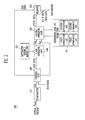
- FIG. 2 illustrates a schematic view of an exemplary data conversion unit as shown in FIG. 1 ;
- FIG. 3A to FIG. 3D illustrate matrices of a desired saturation data in a subpixel calculated in a first operator unit by using a saturation variable matrix as shown in FIG. 2 ;
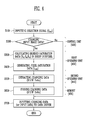
- FIG. 4 illustrates a flow chart of a method for driving a data conversion unit as shown in FIG. 2 .
- an OLED display device 10 may include a pixel unit 100, a scan driver 200, a data driver 300, a data conversion unit 400 and an optical sensor 500. Other devices and/or elements may be included or excluded in the OLED display device 10.
- the pixel unit 100 may include a plurality of pixels 110 connected to scan lines (S1 to Sn), light emission control lines (EM1 to EMn) and data lines (D1 to Dm). Further, a single pixel 110 may have one OLED and may be composed of at least two subpixels for emitting different color light, e.g., red, green and blue.
- the pixel unit 100 may display an image to correspond to a first power source (ELVdd) 120 supplied from the outside and a second power source (ELVss) 140 supplied from the outside.
- the pixel unit 100 may also display images corresponding to scan signals supplied by the scan lines S 1 to Sn and light emission control signals supplied by the emission control lines EM1 to EMn generated from the scan driver 200, and data signals supplied by the data lines D 1 to Dm generated from the data driver 300.
- the scan driver 200 may generate the scan signals and the light emission control signals.
- the scan signals generated in the scan driver 200 may be sequentially supplied to the scan lines (S 1 to Sn) and the light emission control signals may be sequentially supplied to each of the light emission control lines (EM1 to EMn).
- the scan signals and the emission control signals may also be non-sequentially supplied to the scan lines S1 to Sn and the emission control lines EM1 to EMn, respectively.
- the data driver 300 may receive an image data (R'G'B' Data or RGB Data) converted by the control unit 400 and may generate data signals corresponding to the received image data.
- the data signals generated in the data driver 300 may be supplied to the pixels 110 through the data lines (D 1 to Dm) to synchronize with the scan signal.
- the data signals may also be supplied to the data lines D1 to Dm in a non-synchronization manner with the scan signal.
- the optical sensor 500 may include an optical sensor element, e.g., a transistor or a photodiode, to sense an intensity of ambient light.
- the optical sensor 500 may also generate an optical sensor signal (Ssens) corresponding to the sensed intensity of ambient light.
- the optical sensor signal (Ssens) generated in the optical sensor 500 may then be supplied to the data conversion unit 400.
- the data conversion unit 400 may compare the optical sensor signal (Ssens) to predetermined reference values with to generate a selection signal (Ssel) for selecting one of at least three modes, e.g., a first intensity light mode, a second intensity light mode and a third intensity light mode.
- the predetermined reference values may comprise a minimum reference value (weak light intensity) and a maximum reference value (large light intensity).
- the data conversion unit 400 may store an initial input image data (RGB Data) or a changed input image data (R'G'B' Data).
- the initial input image data (RGB Data) may be a signal indicating no change to the input image data (RGB Data) when the signal in the selection signal corresponds to a weak intensity of ambient light, i.e.
- the changed input image data (R'G'B' Data) may be a signal indicating a change to the initial input image data (RGB Data) when the signal in the selection signal corresponds to a large intensity of ambient light, i.e. when the optical sensor signal (Ssel) is above the minimum reference value
- the data conversion unit 400 may generate the changed input image data (R'G'B' Data) so as to control the saturation and/or luminance of the initial input image data (RGB Data) and, thus, enhance visibility.
- the data conversion unit 400 may provide an improved response to light intensity variations in the environment by selecting different modes, e.g., modes to control the initial input image data (RGB Data) corresponding to the optical sensor signal (Ssens).
- the data conversion unit 400 may also perform other operations. For example, determining whether or not to change the initial input image data (RGB Data), generating the changed data (R'G'B' Data) according to the saturation and/or luminance value of the initial input image data (RGB Data) and/or storing the generated changed input image data (R'G'B' Data).
- the selection signal (Ssel) generated in the data conversion unit 400 may then be input to the data driver 300.
- the initial input image data (RGB Data) or the changed input image data (R'G'B' Data) stored in the data conversion unit 400 may be input to the data driver 300.
- the data conversion unit 400 may include a comparator 410, a control unit 420, a first operator unit 430, a saturation variable matrix unit 435, a second operator unit 440, a reference look-up table unit 445 and a memory 450.
- Other devices and/or elements may be included or excluded in the data conversion unit 400.
- the comparator 410 may compare the predetermined reference values with the optical sensor signal (Ssens) supplied from the optical sensor 500 and may output the selection signal (Ssel) for selecting one of at least three modes.
- the comparator 410 may set at least three modes on the basis of the predetermined reference values, which may correspond to the intensity of the optical sensor signal (Ssens).
- the comparator 410 may also set more modes besides three modes.
- the optical sensor signal (Ssens) may be equal to or below the minimum reference value of the predetermined reference values, corresponding to the weakest intensity of ambient light. Accordingly, the initial input image data (RGB Data) may not be changed in the first mode.
- the comparator 410 may therefore output the selection signal (Ssel) corresponding to the first mode.
- the optical sensor signal may be greater than or equal to the maximum reference value of the predetermined reference values, corresponding to the largest intensity of ambient light. Accordingly, the initial input image data (RGB Data) may be changed so as to control the saturation and/or luminance in the second mode.
- the comparator 410 may therefore output the selection signal (Ssel) corresponding to the second mode.
- the optical sensor signal (Ssens) may correspond to a value between the maximum reference value and the minimum reference value of the predetermined reference values. Accordingly, the initial input image data (RGB Data) may be changed so as to control the saturation and/or luminance in the third mode.
- the comparator 410 may therefore output the selection signal (Ssel) corresponding to the third mode. Further, the changed input image data (RGB Data) in the third mode may be set to a lower value than the second mode.
- the selection signal (Ssel) output from the comparator 410 (in at least one mode) may then be input to the control unit 420.
- the control unit 420 may determine whether or not to change the initial input image data (RGB Data), so as to correspond to the selection signal (Ssel) input from the comparator 410.
- the control unit 420 may transmit the initial input image data (RGB Data) to the first operator unit 430 or, alternatively, may transmit the initial input image data (RGB Data) to be stored in the memory 450.
- the transmission to the first operator unit 430 or to the memory 450 may depend on whether or not the initial input image data (RGB Data) is changed.
- control unit 420 may store the initial input image data (RGB Data) in the memory 450 if the intensity of the ambient light is a weak, e.g., the selection signal (Ssel) corresponding to the first mode is supplied. If, however, the selection signal (Ssel) corresponds to the second mode or the third mode, the control unit 420 may transmit the initial input image data (RGB Data) to the first operator unit 430.
- the selection signal (Ssel) corresponds to the second mode or the third mode
- the first operator unit 430 may perform an operation by using a saturation variable matrix A to generate a pixel saturation data (Sout) corresponding to the initial input image data (RGB Data) transmitted from the control unit 420.
- the first operator unit 430 may perform an operation on an input data (Rin, Gin, Bin) and the saturation variable matrix A in each of the subpixels, which may be included in the initial input image data (RGB Data).
- the first operator unit 430 may further calculate a desired saturation data (Rs, Gs, Bs) in every subpixel and may use the calculated saturation data (Rs, Gs, Bs) to generate the pixel saturation data (Sout).
- the pixel saturation data (Sout) may be calculated from the desired saturation data (Rs, Gs, Bs) in every subpixel.
- the pixel saturation data (Sout) may be set to the maximum value of the desired saturation data (Rs, Gs, Bs) in every subpixel, or set to a predetermined value corresponding to a difference between the maximum value and the minimum value of the desired saturation data (Rs, Gs, Bs) in every subpixel.
- the pixel saturation data (Sout) generated in the first operator unit 430 may then be supplied to the second operator unit 440.
- the second operator unit 440 may extract the changed input image data (R'G'B' Data) from the reference look-up table unit 445 so as to correspond to the pixel saturation data (Sout) and the selection signal (Ssel) supplied from the first operator unit 430 and the control unit 420, respectively.
- the second operator unit 440 may further store the extracted changed input image data (R'G'B' Data) in the memory 450.
- the second operator unit 440 may select one of a first saturation and luminance look-up tables (LUTs) and a second saturation and luminance LUTs provided in the reference look-up table unit 445 to correspond to the selection signal (Ssel).
- the second operator unit 440 may extract the changed data (R'G'B' Data) from the selected LUTs, so that the changed data (R'G'B' Data) having the saturation and luminance values may correspond to the pixel saturation data (Sout).
- the saturation LUTs and the luminance LUTs may represent tables to extract a saturation change value and a luminance change value, respectively.
- the first saturation and luminance LUTs and the second saturation and luminance LUTs may store different saturation and luminance values to correspond to the pixel saturation data (Sout).
- the first saturation and luminance LUTs, selected by the selection signal (Ssel) in selecting the third mode may be set to have lower saturation and/or luminance values than the second saturation and luminance LUTs selected by the selection signal (Ssel) in selecting the second mode.
- the second operator unit 440 may extract the changed input image data (R'G'B' Data) by referring to two values of the pixel saturation data (Sout) out of the values stored in the reference look-up table unit 445.
- the second operator unit 440 may extract the changed input image data (R'G'B' Data) by linearly interpolating between a maximum value out of smaller values of the input pixel saturation data (Sout) and a minimum value out of larger values of the input pixel saturation data (Sout).
- the memory 450 may store the initial input image data (RGB Data) transmitted from the control unit 420, or the changed input image data (R'G'B' Data) supplied from the second operator unit 440.
- the initial input image data (RGB Data) or the changed data (R'G'B' Data) stored in the memory 450 may be input to the data driver 300.
- FIG. 3A to FIG. 3D illustrate matrices of a desired saturation data in a subpixel calculated in the first operator unit 430 by using the saturation variable matrix A.
- the first operator unit 430 may calculate the desired saturation data (Rs, Gs, Bs) in every subpixel by multiplying each of the input data (Rin, Gin, Bin) and the saturation variable matrix A in every subpixel.
- the saturation variable matrix A may be a matrix for controlling the saturation by using a saturation coefficient (k) to determine a saturation adjustment. Further, the saturation variable matrix A may be used to calculate each of the desired saturation data (Rs, Gs, Bs) in every subpixel by changing values of the input data (Rin, Gin, Bin) in every subpixel through a previously selected saturation coefficient (k).
- the saturation variable matrix A may be selected according to a white balance of the pixels.
- the first operator unit 430 may calculate the desired saturation data (Rs, Gs, Bs) in every subpixel by multiplying the saturation variable matrix A and the input data (Rin, Gin, Bin) in every subpixel (as illustrated in FIG. 3B ).
- the saturation may be increased if the saturation coefficient (k) has a value larger than 1 and, alternatively, may be decreased if the saturation coefficient (k) has a value smaller than 1.
- the saturation coefficient (k) has a value of 1
- the saturation may remain the same, i.e., unchanged, because the saturation variable matrix A is a 3 x 3 unit matrix (as illustrated in FIG. 3C ).
- the saturation coefficient (k) has a value of 0
- the desired saturation data (Rs, Gs, Bs) in every subpixel may be changed into a saturation-free grey image because the desired saturation data (Rs, Gs, Bs) in every subpixel may be set to the same ratio as the white balance (as illustrated in FIG. 3D ).
- the saturation factor k determining the degree of saturation change can be freely determined by a planner and also it can be determined to display the optimum visibility according to an experiment: for example, when the display device displays an image under various conditions a saturation variation may be adjusted to the corresponding visibility to determine the optimum saturation factor k.
- the comparator 410 may compare the optical sensor signal (Ssens) to the predetermined reference values to generate the selection signal (Ssel) for selecting one of at least three modes.
- the selection signal (Ssel) may be set to select: a) the first mode, if the optical sensor signal (Ssens) corresponds to a weak intensity of ambient light; b) the second mode, if the optical sensor signal (Ssens) corresponds to a large intensity of ambient light; and c) the third mode, if the optical sensor signal (Ssens) corresponds to a value between the weak and large intensity of ambient light.
- the input image data (RGB Data) may remain the same, e.g., unchanged, and in the second and third modes the input image data (RGB Data) may be changed, i.e. at least one of luminance and saturation of the input image data (RGB Data) may be changed.
- the selection signal (Ssel) generated in the comparator 410 may be input to the control unit 420.
- the control unit 420 receiving the selection signal (Ssel) may determine whether or not to change the initial input image data (RGB Data), so as to correspond to the selection signal (Ssel). Accordingly, if the selection signal (Ssel) selects the first mode and inputs to the control unit 420, the control unit 420 may supply the initial input image data (RGB Data) to the data driver 300 without changing the initial input image data (RGB Data). Further, the initial input image data (RGB Data) may be temporarily stored in the memory 450 by the control unit 420 and then input to the data driver 300.
- control unit 420 may transmit the initial input image data (RGB Data) to the first operator unit 430, or may alternatively transmit the received selection signal (Ssel) to the second operator unit 440 (if the selection signal (Ssel) for selecting the second or third mode is input to the control unit 420).
- the first operator unit 430 may calculate the desired saturation data (Rs, Gs, Bs) in every subpixel by carrying out an operation on the initial input data (Rin, Gin, Bin) and the saturation variable matrix A.
- the first operator unit 430 may further generate a pixel saturation data (Sout) corresponding to the desired saturation data (Rs, Gs, Bs).
- the first operator unit 430 may also supply the generated pixel saturation data (Sout) to the second operator unit 440.
- the second operator unit 440 may then extract the changed input image data (R'G'B' Data) to change the saturation and/or luminance of the initial input image data (RGB Data) from the reference look-up table unit 445.
- the second operator unit 440 may also store the extracted changed data (R'G'B' Data) corresponding to the selection signal (Ssel) and the pixel saturation data (Sout) in the memory 450.
- the second operator unit 440 may select one of at least two saturation and luminance LUTs stored in the reference look-up table unit 445 and may extract the changed input image data (R'G'B' Data) from the selected look-up table to correspond to the selection signal (Ssel).
- the second operator unit 440 may extract the changed input image data (R'G'B' Data) corresponding to the pixel saturation data (Sout) using linear interpolations.
- the extracted changed input image data (R'G'B' Data) may be stored in the memory 450, in S600.
- the changed input image data (R'G'B' Data) stored in the memory 450 may be input to the data driver 300 and then used to generate a data signal.
- Exemplary embodiments of the present invention relate to an OLED display device and driving methods thereof, having improved visibility by changing input image data to correspond to surrounding environments, e.g., intensity of ambient light.
- the OLED display device and driving methods thereof may further improve visibility under ambient light by generating a changed input image data to enhance saturation and the like.
- the OLED display device and driving methods thereof may further improve visibility under ambient light by displaying images corresponding to a generated changed input image data when the OLED display device is exposed to ambient light having a greater illumination intensity value than a predetermined reference value.
- the OLED display device and driving methods thereof may further improve the response to intensity variations of ambient light by selecting one of at least three modes for controlling an input image data to be changed.
Landscapes
- Engineering & Computer Science (AREA)
- Physics & Mathematics (AREA)
- General Physics & Mathematics (AREA)
- Computer Hardware Design (AREA)
- Theoretical Computer Science (AREA)
- Spectroscopy & Molecular Physics (AREA)
- Control Of Indicators Other Than Cathode Ray Tubes (AREA)
- Control Of El Displays (AREA)
- Electroluminescent Light Sources (AREA)
Abstract
Description
- Exemplary embodiments relate to an organic light emitting diode (OLED) display device and driving methods thereof and, more particularly, to an OLED display device having improved display and visibility across varying ambient light conditions and driving methods thereof.
- Various flat display technologies, i.e., plasma display panels (PDPs), liquid crystal displays (LCDs) and OLED displays, are becoming widely used over other display devices, e.g., cathode ray tubes (CRTs), due to their small size, reduced weight and volume and energy efficiency characteristics. When comparing the various flat display technologies, however, the OLED displays may provide better luminance feature and color purity because OLED displays use an organic compound as an emitting material. Further, due to their reduced size and weight, the OLED displays may be incorporated into portable display devices, e.g., cellular phones, personal digital assistant devices, portable multimedia players and the like. Since the portable display devices may be exposed to varying light conditions, e.g., exposed to outdoor visible light, quality and visibility (or viewability) of images displayed on the portable display device may be diminished. In other words, brightness of images displayed on the portable display device may be diminished (or faded out) under light, e.g., solar light, because surrounding or ambient light and/or illumination intensity may be brighter than the brightness of the displayed image.
- Therefore, there is a need for the development of an OLED display having improved display and visibility across varying ambient light conditions, and methods of driving such devices.
- Exemplary embodiments are related to an OLED display device and driving methods thereof, which substantially overcome one or more of the problems due to the limitations and disadvantages of the related art.
- It is therefore a feature of exemplary embodiments to provide an OLED display device having improved display and visibility across varying ambient light conditions.
- according to an exemplary embodiment of the present invention, an OLED display device includes a pixel unit having a plurality of pixels connected to scan lines and data lines, a scan driver adapted to generate and supply scan signals to the scan lines, a data driver adapted to generate and supply data signals to the data lines, an optical sensor adapted to generate an optical sensor signal corresponding to an intensity of light, and a data conversion unit adapted to compare a predetermined reference value with the optical sensor signal so as to generate a selection signal for selecting one of at least three modes. The data conversion unit is adapted to store an input image data or a changed input image data to correspond with the selection signal. The data driver is adapted to generate the data signals to correspond to the input image data or the changed input image data stored in the data conversion unit.
- The data conversion unit may further include a comparator, a control unit adapted to determine changing the input image data to correspond to the selection signal, a first operator unit adapted to generate a pixel saturation data to correspond to the input image data transmitted from the control unit, a second operator unit adapted to extract the changed input image data to correspond to the pixel saturation data and the selection signal, and a memory adapted to store the input image data transmitted from the control unit or the changed input image data supplied from the second operator unit.
- In a first mode, the control unit may be adapted to store the input image data in the memory if the selection signal indicates a weak intensity of light. In a second mode, the control unit may be adapted to transmit the input image data to the first operator unit and adapted to transmit the selection signal to the second operator unit if the selection signal indicates a large intensity of light. In a third mode, the control unit may be adapted to transmit the input image data to the first operator unit and adapted to transmit the selection signal to the second operator unit if the selection signal indicates a value between the weak intensity of light and the large intensity of light. The changed input image data in the third mode may be set to a lower value than the second mode.
- The first operator unit may be adapted to perform an operation using a saturation variable matrix. The first operator unit may be adapted to calculate a desired saturation data in every subpixel by performing an operation on an input data in the input image data and the saturation variable matrix in every subpixel.
- The OLED display device may further include a reference look-up table unit calculated by the second operator unit. The reference look-up table unit may include a first saturation and luminance look-up tables and a second saturation and luminance look-up tables. The second operator unit may be adapted to select one of the first saturation and luminance look-up tables and the second saturation and luminance look-up tables to correspond to the pixel saturation data and the selection signal. The second operator unit may be adapted to extract the changed input image data from the selected look-up tables. Alternatively, the second operator unit may be adapted to extract the changed input image data by linearly interpolating between two values of the pixel saturation data stored in the reference look-up table unit, if a pixel saturation data that is not stored in the reference look-up table unit is input.
- According to another exemplary embodiment, a method for driving an OLED display deviceincludes supplying scan signals to scan lines generated by a scan driver, supplying data signals to data lines generated by a data driver, generating an optical sensing signal corresponding to an intensity of light sensed on an optical sensor, generating a selection signal for selecting one of at least three modes to correspond to the intensity of light, and storing an input image data or a changed input image data to correspond with the selection signal. The data driver generates the data signals to correspond to the input image data or the changed input image data stored in a data conversion unit.
- The method may further include determining whether to change the input image data to correspond to the selection signal, and extracting data when the changed input image data is determined. The changed data may be obtained by changing at least one of a saturation and a luminance of the input image data. The extracted changed input image data may further include generating a pixel saturation data from the input image data, and extracting the changed input image data from a reference look-up table unit to correspond to the pixel saturation data and the selection signal. The generated pixel saturation data may further include calculating a desired saturation data in every subpixel by performing an operation on the input image data and the saturation variable matrix, and generating the pixel saturation data to correspond to the desired saturation data in every subpixel.
- The method may further include extracting the changed input image data by linearly interpolating between two values of the pixel saturation data among values stored in the reference look-up table unit if a pixel saturation data not stored in the reference look-up table unit is input.
- The method may further include selecting a signal for selecting a mode in the selection signal corresponding to a weak intensity of light, so that the input image data may remain unchanged. The method may further include selecting a signal for selecting a mode in the selection signal corresponding to a large intensity of light, so as to change the input image data.
- The method may further include storing the input image data and generating a data signal corresponding to the stored input image data.
- The above and other features and advantages of the exemplary embodiments will become more apparent to those of ordinary skill in the art by describing in detail exemplary embodiments thereof with reference to the attached drawings, of which:
-
FIG. 1 illustrates a schematic view of an OLED display device according to an exemplary embodiment; -
FIG. 2 illustrates a schematic view of an exemplary data conversion unit as shown inFIG. 1 ; -
FIG. 3A to FIG. 3D illustrate matrices of a desired saturation data in a subpixel calculated in a first operator unit by using a saturation variable matrix as shown inFIG. 2 ; and -
FIG. 4 illustrates a flow chart of a method for driving a data conversion unit as shown inFIG. 2 . - Korean Patent Application No.
10-2007-0018696, filed on February 23, 2007 - Exemplary embodiments will now be described more fully hereinafter with reference to the accompanying drawings; however, the exemplary embodiments may be embodied in different forms and should not be construed as limited to the embodiments set forth herein. Rather, these exemplary embodiments are provided so that this disclosure will be thorough and complete, and will fully convey the scope of the invention to those skilled in the art.
- Referring to
FIG. 1 , anOLED display device 10 may include apixel unit 100, ascan driver 200, adata driver 300, adata conversion unit 400 and anoptical sensor 500. Other devices and/or elements may be included or excluded in theOLED display device 10. - The
pixel unit 100 may include a plurality ofpixels 110 connected to scan lines (S1 to Sn), light emission control lines (EM1 to EMn) and data lines (D1 to Dm). Further, asingle pixel 110 may have one OLED and may be composed of at least two subpixels for emitting different color light, e.g., red, green and blue. - The
pixel unit 100 may display an image to correspond to a first power source (ELVdd) 120 supplied from the outside and a second power source (ELVss) 140 supplied from the outside. Thepixel unit 100 may also display images corresponding to scan signals supplied by thescan lines S 1 to Sn and light emission control signals supplied by the emission control lines EM1 to EMn generated from thescan driver 200, and data signals supplied by thedata lines D 1 to Dm generated from thedata driver 300. - The
scan driver 200 may generate the scan signals and the light emission control signals. The scan signals generated in thescan driver 200 may be sequentially supplied to the scan lines (S 1 to Sn) and the light emission control signals may be sequentially supplied to each of the light emission control lines (EM1 to EMn). The scan signals and the emission control signals may also be non-sequentially supplied to the scan lines S1 to Sn and the emission control lines EM1 to EMn, respectively. - The
data driver 300 may receive an image data (R'G'B' Data or RGB Data) converted by thecontrol unit 400 and may generate data signals corresponding to the received image data. The data signals generated in thedata driver 300 may be supplied to thepixels 110 through the data lines (D 1 to Dm) to synchronize with the scan signal. The data signals may also be supplied to the data lines D1 to Dm in a non-synchronization manner with the scan signal. - The
optical sensor 500 may include an optical sensor element, e.g., a transistor or a photodiode, to sense an intensity of ambient light. Theoptical sensor 500 may also generate an optical sensor signal (Ssens) corresponding to the sensed intensity of ambient light. The optical sensor signal (Ssens) generated in theoptical sensor 500 may then be supplied to thedata conversion unit 400. - The
data conversion unit 400 may compare the optical sensor signal (Ssens) to predetermined reference values with to generate a selection signal (Ssel) for selecting one of at least three modes, e.g., a first intensity light mode, a second intensity light mode and a third intensity light mode. The predetermined reference values may comprise a minimum reference value (weak light intensity) and a maximum reference value (large light intensity). Further, thedata conversion unit 400 may store an initial input image data (RGB Data) or a changed input image data (R'G'B' Data). The initial input image data (RGB Data) may be a signal indicating no change to the input image data (RGB Data) when the signal in the selection signal corresponds to a weak intensity of ambient light, i.e. when the optical sensor signal (Ssel) is below or equal to the minimum reference value. The changed input image data (R'G'B' Data) may be a signal indicating a change to the initial input image data (RGB Data) when the signal in the selection signal corresponds to a large intensity of ambient light, i.e. when the optical sensor signal (Ssel) is above the minimum reference value Further, thedata conversion unit 400 may generate the changed input image data (R'G'B' Data) so as to control the saturation and/or luminance of the initial input image data (RGB Data) and, thus, enhance visibility. Further, when the changed input image data (R'G'B' Data) is generated, thedata conversion unit 400 may provide an improved response to light intensity variations in the environment by selecting different modes, e.g., modes to control the initial input image data (RGB Data) corresponding to the optical sensor signal (Ssens). - The
data conversion unit 400 may also perform other operations. For example, determining whether or not to change the initial input image data (RGB Data), generating the changed data (R'G'B' Data) according to the saturation and/or luminance value of the initial input image data (RGB Data) and/or storing the generated changed input image data (R'G'B' Data). - The selection signal (Ssel) generated in the
data conversion unit 400 may then be input to thedata driver 300. In particular, the initial input image data (RGB Data) or the changed input image data (R'G'B' Data) stored in thedata conversion unit 400 may be input to thedata driver 300. - Referring to
FIG. 2 , thedata conversion unit 400 may include acomparator 410, acontrol unit 420, afirst operator unit 430, a saturationvariable matrix unit 435, asecond operator unit 440, a reference look-uptable unit 445 and amemory 450. Other devices and/or elements may be included or excluded in thedata conversion unit 400. - The
comparator 410 may compare the predetermined reference values with the optical sensor signal (Ssens) supplied from theoptical sensor 500 and may output the selection signal (Ssel) for selecting one of at least three modes. Thecomparator 410 may set at least three modes on the basis of the predetermined reference values, which may correspond to the intensity of the optical sensor signal (Ssens). Thecomparator 410 may also set more modes besides three modes. - In a first mode, the optical sensor signal (Ssens) may be equal to or below the minimum reference value of the predetermined reference values, corresponding to the weakest intensity of ambient light. Accordingly, the initial input image data (RGB Data) may not be changed in the first mode. The
comparator 410 may therefore output the selection signal (Ssel) corresponding to the first mode. - In a second mode, the optical sensor signal (Ssens) may be greater than or equal to the maximum reference value of the predetermined reference values, corresponding to the largest intensity of ambient light. Accordingly, the initial input image data (RGB Data) may be changed so as to control the saturation and/or luminance in the second mode. The
comparator 410 may therefore output the selection signal (Ssel) corresponding to the second mode. - In a third mode, the optical sensor signal (Ssens) may correspond to a value between the maximum reference value and the minimum reference value of the predetermined reference values. Accordingly, the initial input image data (RGB Data) may be changed so as to control the saturation and/or luminance in the third mode. The
comparator 410 may therefore output the selection signal (Ssel) corresponding to the third mode. Further, the changed input image data (RGB Data) in the third mode may be set to a lower value than the second mode. - The selection signal (Ssel) output from the comparator 410 (in at least one mode) may then be input to the
control unit 420. Thecontrol unit 420 may determine whether or not to change the initial input image data (RGB Data), so as to correspond to the selection signal (Ssel) input from thecomparator 410. - The
control unit 420 may transmit the initial input image data (RGB Data) to thefirst operator unit 430 or, alternatively, may transmit the initial input image data (RGB Data) to be stored in thememory 450. The transmission to thefirst operator unit 430 or to thememory 450 may depend on whether or not the initial input image data (RGB Data) is changed. - In an implementation, the
control unit 420 may store the initial input image data (RGB Data) in thememory 450 if the intensity of the ambient light is a weak, e.g., the selection signal (Ssel) corresponding to the first mode is supplied. If, however, the selection signal (Ssel) corresponds to the second mode or the third mode, thecontrol unit 420 may transmit the initial input image data (RGB Data) to thefirst operator unit 430. - The
first operator unit 430 may perform an operation by using a saturation variable matrix A to generate a pixel saturation data (Sout) corresponding to the initial input image data (RGB Data) transmitted from thecontrol unit 420. Thefirst operator unit 430 may perform an operation on an input data (Rin, Gin, Bin) and the saturation variable matrix A in each of the subpixels, which may be included in the initial input image data (RGB Data). Thefirst operator unit 430 may further calculate a desired saturation data (Rs, Gs, Bs) in every subpixel and may use the calculated saturation data (Rs, Gs, Bs) to generate the pixel saturation data (Sout). - A method of calculating the desired saturation data (Rs, Gs, Bs) in every subpixel will be described later as illustrated in
FIG. 3A to FIG. 3D . - The pixel saturation data (Sout) may be calculated from the desired saturation data (Rs, Gs, Bs) in every subpixel. For example, the pixel saturation data (Sout) may be set to the maximum value of the desired saturation data (Rs, Gs, Bs) in every subpixel, or set to a predetermined value corresponding to a difference between the maximum value and the minimum value of the desired saturation data (Rs, Gs, Bs) in every subpixel.
- The pixel saturation data (Sout) generated in the
first operator unit 430 may then be supplied to thesecond operator unit 440. Thesecond operator unit 440 may extract the changed input image data (R'G'B' Data) from the reference look-uptable unit 445 so as to correspond to the pixel saturation data (Sout) and the selection signal (Ssel) supplied from thefirst operator unit 430 and thecontrol unit 420, respectively. Thesecond operator unit 440 may further store the extracted changed input image data (R'G'B' Data) in thememory 450. - The
second operator unit 440 may select one of a first saturation and luminance look-up tables (LUTs) and a second saturation and luminance LUTs provided in the reference look-uptable unit 445 to correspond to the selection signal (Ssel). Thesecond operator unit 440 may extract the changed data (R'G'B' Data) from the selected LUTs, so that the changed data (R'G'B' Data) having the saturation and luminance values may correspond to the pixel saturation data (Sout). The saturation LUTs and the luminance LUTs may represent tables to extract a saturation change value and a luminance change value, respectively. The first saturation and luminance LUTs and the second saturation and luminance LUTs may store different saturation and luminance values to correspond to the pixel saturation data (Sout). For example, the first saturation and luminance LUTs, selected by the selection signal (Ssel) in selecting the third mode, may be set to have lower saturation and/or luminance values than the second saturation and luminance LUTs selected by the selection signal (Ssel) in selecting the second mode. - Further, the
second operator unit 440 may extract the changed input image data (R'G'B' Data) by referring to two values of the pixel saturation data (Sout) out of the values stored in the reference look-uptable unit 445. For example, thesecond operator unit 440 may extract the changed input image data (R'G'B' Data) by linearly interpolating between a maximum value out of smaller values of the input pixel saturation data (Sout) and a minimum value out of larger values of the input pixel saturation data (Sout). - The
memory 450 may store the initial input image data (RGB Data) transmitted from thecontrol unit 420, or the changed input image data (R'G'B' Data) supplied from thesecond operator unit 440. The initial input image data (RGB Data) or the changed data (R'G'B' Data) stored in thememory 450 may be input to thedata driver 300. -
FIG. 3A to FIG. 3D illustrate matrices of a desired saturation data in a subpixel calculated in thefirst operator unit 430 by using the saturation variable matrix A. - Referring to
FIG. 3A to FIG. 3D , thefirst operator unit 430 may calculate the desired saturation data (Rs, Gs, Bs) in every subpixel by multiplying each of the input data (Rin, Gin, Bin) and the saturation variable matrix A in every subpixel. - The saturation variable matrix A may be a matrix for controlling the saturation by using a saturation coefficient (k) to determine a saturation adjustment. Further, the saturation variable matrix A may be used to calculate each of the desired saturation data (Rs, Gs, Bs) in every subpixel by changing values of the input data (Rin, Gin, Bin) in every subpixel through a previously selected saturation coefficient (k).
- The saturation variable matrix A may be selected according to a white balance of the pixels. In other words, the
first operator unit 430 may calculate the desired saturation data (Rs, Gs, Bs) in every subpixel by multiplying the saturation variable matrix A and the input data (Rin, Gin, Bin) in every subpixel (as illustrated inFIG. 3B ). - Further, the saturation may be increased if the saturation coefficient (k) has a value larger than 1 and, alternatively, may be decreased if the saturation coefficient (k) has a value smaller than 1. When the saturation coefficient (k) has a value of 1, then the saturation may remain the same, i.e., unchanged, because the saturation variable matrix A is a 3 x 3 unit matrix (as illustrated in
FIG. 3C ). When the saturation coefficient (k) has a value of 0, then the desired saturation data (Rs, Gs, Bs) in every subpixel may be changed into a saturation-free grey image because the desired saturation data (Rs, Gs, Bs) in every subpixel may be set to the same ratio as the white balance (as illustrated inFIG. 3D ). The saturation factor k determining the degree of saturation change can be freely determined by a planner and also it can be determined to display the optimum visibility according to an experiment: for example, when the display device displays an image under various conditions a saturation variation may be adjusted to the corresponding visibility to determine the optimum saturation factor k. - Referring back to
FIG. 2 , if the optical sensor signal (Ssens) corresponding to the intensity of ambient light is input from theoptical sensor 500 to thecomparator 410, thecomparator 410 may compare the optical sensor signal (Ssens) to the predetermined reference values to generate the selection signal (Ssel) for selecting one of at least three modes. In particular, the selection signal (Ssel) may be set to select: a) the first mode, if the optical sensor signal (Ssens) corresponds to a weak intensity of ambient light; b) the second mode, if the optical sensor signal (Ssens) corresponds to a large intensity of ambient light; and c) the third mode, if the optical sensor signal (Ssens) corresponds to a value between the weak and large intensity of ambient light. In the first mode the input image data (RGB Data) may remain the same, e.g., unchanged, and in the second and third modes the input image data (RGB Data) may be changed, i.e. at least one of luminance and saturation of the input image data (RGB Data) may be changed. - Now an operation for driving the
data conversion unit 400 will be discussed in detail. - Referring to
FIG. 4 , in S100, the selection signal (Ssel) generated in thecomparator 410 may be input to thecontrol unit 420. - In S200, the
control unit 420 receiving the selection signal (Ssel) may determine whether or not to change the initial input image data (RGB Data), so as to correspond to the selection signal (Ssel). Accordingly, if the selection signal (Ssel) selects the first mode and inputs to thecontrol unit 420, thecontrol unit 420 may supply the initial input image data (RGB Data) to thedata driver 300 without changing the initial input image data (RGB Data). Further, the initial input image data (RGB Data) may be temporarily stored in thememory 450 by thecontrol unit 420 and then input to thedata driver 300. - Further, the
control unit 420 may transmit the initial input image data (RGB Data) to thefirst operator unit 430, or may alternatively transmit the received selection signal (Ssel) to the second operator unit 440 (if the selection signal (Ssel) for selecting the second or third mode is input to the control unit 420). - In S300, the
first operator unit 430 may calculate the desired saturation data (Rs, Gs, Bs) in every subpixel by carrying out an operation on the initial input data (Rin, Gin, Bin) and the saturation variable matrix A. - In S400, the
first operator unit 430 may further generate a pixel saturation data (Sout) corresponding to the desired saturation data (Rs, Gs, Bs). Thefirst operator unit 430 may also supply the generated pixel saturation data (Sout) to thesecond operator unit 440. - In S500, the
second operator unit 440 may then extract the changed input image data (R'G'B' Data) to change the saturation and/or luminance of the initial input image data (RGB Data) from the reference look-uptable unit 445. Thesecond operator unit 440 may also store the extracted changed data (R'G'B' Data) corresponding to the selection signal (Ssel) and the pixel saturation data (Sout) in thememory 450. In particular, thesecond operator unit 440 may select one of at least two saturation and luminance LUTs stored in the reference look-uptable unit 445 and may extract the changed input image data (R'G'B' Data) from the selected look-up table to correspond to the selection signal (Ssel). - If the changed input image data (R'G'B' Data) corresponding to the pixel saturation data (Sout) supplied from the
first operator unit 430 is not stored in the reference look-uptable unit 445, then thesecond operator unit 440 may extract the changed input image data (R'G'B' Data) corresponding to the pixel saturation data (Sout) using linear interpolations. The extracted changed input image data (R'G'B' Data) may be stored in thememory 450, in S600. - In S700, the changed input image data (R'G'B' Data) stored in the
memory 450 may be input to thedata driver 300 and then used to generate a data signal. - Exemplary embodiments of the present invention relate to an OLED display device and driving methods thereof, having improved visibility by changing input image data to correspond to surrounding environments, e.g., intensity of ambient light. The OLED display device and driving methods thereof may further improve visibility under ambient light by generating a changed input image data to enhance saturation and the like. The OLED display device and driving methods thereof may further improve visibility under ambient light by displaying images corresponding to a generated changed input image data when the OLED display device is exposed to ambient light having a greater illumination intensity value than a predetermined reference value. The OLED display device and driving methods thereof may further improve the response to intensity variations of ambient light by selecting one of at least three modes for controlling an input image data to be changed.
- Exemplary embodiments have been disclosed herein, and although specific terms are employed, they are used and are to be interpreted in a generic and descriptive sense only and not for purpose of limitation. Accordingly, it will be understood by those of ordinary skill in the art that various changes in form and details may be made without departing from the scope of the present invention as set forth in the following claims.
Claims (18)
- An organic light emitting diode (OLED) display device, comprising:a pixel unit (100) including a plurality of pixels (110) connected to scan lines (S1, S2, Sn) and data lines (D1, D2, Dm);a scan driver (200) adapted to generate and supply scan signals to the scan lines (S1, S2, Sn);a data driver (300) adapted to generate and supply data signals to the data lines (D1, D2, Dm);an optical sensor (500) adapted to generate an optical sensor signal (Ssens) corresponding to an intensity of light of the environment; anda data conversion unit (400) adapted to compare the optical sensor signal (Ssens) with predetermined reference values so as to generate a selection signal (Ssel) for selecting one of at least three light intensity modes, the data conversion unit (400) being adapted to store an input image data (RGB Data) or a changed input image data (R'G'B' Data) according to the selection signal (Ssel),wherein the data driver (300) is adapted to generate the data signals to correspond to the input image data (RGB Data) or the changed input image data (R'G'B' Data) stored in the data conversion unit (400).
- The OLED display device as claimed in claim 1, wherein the data conversion unit (400) further comprises:a comparator (410);a control unit (420) adapted to determine whether a change in the input image data (RGB Data) is required according to the selection signal (Ssel);a first operator unit (430) adapted to generate a pixel saturation data (Sout) corresponding to the input image data (RGB Data) transmitted from the control unit (420);a second operator unit (440) adapted to extract the changed input image data (R'G'B' Data) corresponding to the pixel saturation data (Sout) and the selection signal (Ssel); anda memory (450) adapted to store the input image data (RGB Data) transmitted from the control unit (420) or the changed input image data (R'G'B' Data) supplied from the second operator unit (440).
- The OLED display device as claimed in one of claims 1 and 2, wherein the predetermined reference values comprise a minimum reference value, corresponding to a weak light intensity, and a maximum reference value, corresponding to a large light intensity,
wherein the selection signal (Ssel) corresponds to the first light intensity mode, when the optical sensor signal (Ssens) is below or equal to the minimum reference value,
wherein the selection signal (Ssel) corresponds to the second light intensity mode, when the optical sensor signal (Ssens) is above or equal to the maximum reference value, and
wherein the selection signal (Ssel) corresponds to the third light intensity mode, when the optical sensor signal (Ssens) is above the minimum reference value and below the maximum reference value. - The OLED display device as claimed in claim 3, wherein, in the first light intensity mode, the control unit (420) is adapted to store the input image data (RGB Data) in the memory (450).
- The OLED display device as claimed in claim 3, wherein, in the second and third light intensity modes, the control unit (420) is adapted to transmit the input image data (RGB Data) to the first operator unit (430) and to transmit the selection signal (Ssel) to the second operator unit (440).
- The OLED display device as claimed in claim 5, wherein the luminosity of the changed input image data (R'G'B' Data) in the third light intensity mode is set to a lower value than in the second light intensity mode.
- The OLED display device as claimed in one of claims 2-6, wherein the first operator unit (430) is adapted to perform an operation using a saturation variable matrix (A, 435).
- The OLED display device as claimed in claim 7, wherein the first operator unit (430) is adapted to calculate a desired saturation data (Rs, Gs, Bs) in every subpixel by performing an operation on an input data in the input image data (RGB Data) and the saturation variable matrix (A, 435) in every subpixel.
- The OLED display device as claimed in one of claims 2-8, further comprising a reference look-up table unit (445), the reference look-up table unit (445) including a first saturation and luminance look-up tables and a second saturation and luminance look-up tables.
- The OLED display device as claimed in claim 9, wherein the second operator unit (440) is adapted to select one of the first saturation and luminance look-up tables and the second saturation and luminance look-up tables according to the pixel saturation data (Sout) and the selection signal (Ssel), and to extract the changed input image data (R'G'B' Data) from the selected look-up tables.
- The OLED display device as claimed in claim 9, wherein the second operator unit (440) is adapted to extract the changed input image data (R'G'B' Data) by linearly interpolating between two values of the pixel saturation data stored in the reference look-up table unit (445), if a pixel saturation data (Sout) that is not stored in the reference look-up table unit (445) is input.
- A method for driving an organic light emitting diode (OLED) display device, comprising:supplying scan signals to scan lines (S1, S2, Sn) generated by a scan driver (200);supplying data signals to data lines (D1, D2, Dm) generated by a data driver (300);generating an optical sensing signal (Ssens) corresponding to an intensity of light of the environment sensed by an optical sensor (500);generating a selection signal (Ssel) for selecting one of at least three light intensity modes according to the intensity of light of the environment; andstoring an input image data (RGB Data) or a changed input image data (R'G'B' Data) according to the selection signal (Ssel),wherein the data driver (300) generates the data signals to correspond to the input image data (RGB Data) or the changed input image data (R'G'B' Data) stored in a data conversion unit (400).
- The method for driving the OLED display device as claimed in claim 12, further comprising:comparing the optical sensing signal (Ssens) to predetermined reference values, the predetermined reference values comprising a minimum reference value and a maximun reference value;generating a selection signal (Ssel) corresponding to a first light intensity mode, when the optical sensor signal (Ssens) is below or equal to the minimum reference value,generating a selection signal (Ssel) corresponding to a second light intensity mode, when the optical sensor signal (Ssens) is above or equal to the maximum reference value, andgenerating a selection signal (Ssel) corresponding to a third light intensity mode, when the optical sensor signal (Ssens) is above the minimum reference value and below the maximum reference value.
- The method for driving the OLED display device as claimed in one of claims 12 and 13, further comprising:determining whether to change the input image data (RGB Data) according to the selection signal (Ssel); andextracting the changed input image data (R'G'B' Data) by changing at least one of a saturation and a luminance of the input image data (RGB Data), when the selection signal (Ssel) indicates that the input image data (RGB Data) has to be changed.
- The method for driving the OLED display device as claimed in claim 14, wherein extracting the changed input image data (R'G'B' Data) further comprises:generating a pixel saturation data (Sout) from the input image data (RGB Data); andextracting the changed input image data (R'G'B' Data) from a reference look-up table unit (445) to correspond to the pixel saturation data (Sout) and the selection signal (Ssel).
- The method for driving the OLED display device as claimed in claim 15, wherein generating the pixel saturation data (Sout) further comprises:calculating a desired saturation data (Rs, Gs, Bs) in every subpixel by performing an operation on the input image data (RGB Data) and the saturation variable matrix (A, 435); andgenerating the pixel saturation data (Sout) to correspond to the desired saturation data (Rs, Gs, Bs) in every subpixel.
- The method for driving the OLED display device as claimed in one of claims 15 and 16, further comprising extracting the changed input image data (R'G'B' Data) by linearly interpolating between two values of the pixel saturation data among values stored in the reference look-up table unit (445) if a pixel saturation data (Sout) not stored in the reference look-up table unit (445) is input.
- The method for driving the OLED display device as claimed in one of claims 13-17, wherein the input image data (RGB Data) remains unchanged when the selection signal (Ssel) corresponds to the first light intensity mode, and at least one of luminosity and saturation of the input image data (RGB Data) is changed when the selection signal (Ssel) corresponds to the second or third light intensity mode.
Applications Claiming Priority (1)
| Application Number | Priority Date | Filing Date | Title |
|---|---|---|---|
| KR1020070018696A KR100844780B1 (en) | 2007-02-23 | 2007-02-23 | Organic EL display device and driving method thereof |
Publications (2)
| Publication Number | Publication Date |
|---|---|
| EP1962266A1 true EP1962266A1 (en) | 2008-08-27 |
| EP1962266B1 EP1962266B1 (en) | 2012-04-18 |
Family
ID=39322919
Family Applications (1)
| Application Number | Title | Priority Date | Filing Date |
|---|---|---|---|
| EP08151743A Active EP1962266B1 (en) | 2007-02-23 | 2008-02-21 | Organic light emitting diode display device and driving method thereof |
Country Status (5)
| Country | Link |
|---|---|
| US (1) | US8059069B2 (en) |
| EP (1) | EP1962266B1 (en) |
| JP (1) | JP2008209881A (en) |
| KR (1) | KR100844780B1 (en) |
| CN (1) | CN101251983B (en) |
Cited By (1)
| Publication number | Priority date | Publication date | Assignee | Title |
|---|---|---|---|---|
| EP2339568A1 (en) * | 2009-12-22 | 2011-06-29 | Samsung Electronics Co., Ltd. | Data display method and device |
Families Citing this family (18)
| Publication number | Priority date | Publication date | Assignee | Title |
|---|---|---|---|---|
| KR100844775B1 (en) * | 2007-02-23 | 2008-07-07 | 삼성에스디아이 주식회사 | Organic electroluminescent display |
| KR100916913B1 (en) * | 2008-05-13 | 2009-09-09 | 삼성모바일디스플레이주식회사 | Organic light emitting display |
| KR101330485B1 (en) * | 2010-05-27 | 2013-11-20 | 엘지디스플레이 주식회사 | Organic Light Emitting Diode Display And Chromaticity Coordinates Compensating Method Thereof |
| TWI423198B (en) | 2011-04-20 | 2014-01-11 | Wistron Corp | Display apparatus and method for adjusting gray-level of screen image depending on environment illumination |
| KR20190130079A (en) * | 2011-09-23 | 2019-11-20 | 매뉴팩처링 리소시스 인터내셔널 인코포레이티드 | System and method for environmental adaptation of display characteristics |
| US10607520B2 (en) | 2015-05-14 | 2020-03-31 | Manufacturing Resources International, Inc. | Method for environmental adaptation of display characteristics based on location |
| US10593255B2 (en) | 2015-05-14 | 2020-03-17 | Manufacturing Resources International, Inc. | Electronic display with environmental adaptation of display characteristics based on location |
| US10321549B2 (en) | 2015-05-14 | 2019-06-11 | Manufacturing Resources International, Inc. | Display brightness control based on location data |
| CN105118436A (en) * | 2015-09-16 | 2015-12-02 | 中国科学院上海高等研究院 | AMOLED display driving circuit and brightness adjustment method |
| US10586508B2 (en) | 2016-07-08 | 2020-03-10 | Manufacturing Resources International, Inc. | Controlling display brightness based on image capture device data |
| WO2018067056A1 (en) * | 2016-10-05 | 2018-04-12 | Telefonaktiebolaget Lm Ericsson (Publ) | An efficient lut implementation of luma adjustment |
| CN106531081B (en) | 2017-01-23 | 2019-06-07 | 武汉华星光电技术有限公司 | A kind of display module driving device and method |
| US10578658B2 (en) | 2018-05-07 | 2020-03-03 | Manufacturing Resources International, Inc. | System and method for measuring power consumption of an electronic display assembly |
| US10782276B2 (en) | 2018-06-14 | 2020-09-22 | Manufacturing Resources International, Inc. | System and method for detecting gas recirculation or airway occlusion |
| US11526044B2 (en) | 2020-03-27 | 2022-12-13 | Manufacturing Resources International, Inc. | Display unit with orientation based operation |
| KR20230154964A (en) | 2021-03-15 | 2023-11-09 | 매뉴팩처링 리소시스 인터내셔널 인코포레이티드 | Fan control for electronic display assemblies |
| US12105370B2 (en) | 2021-03-15 | 2024-10-01 | Manufacturing Resources International, Inc. | Fan control for electronic display assemblies |
| US12027132B1 (en) | 2023-06-27 | 2024-07-02 | Manufacturing Resources International, Inc. | Display units with automated power governing |
Citations (3)
| Publication number | Priority date | Publication date | Assignee | Title |
|---|---|---|---|---|
| US20010050757A1 (en) | 2000-05-15 | 2001-12-13 | Yasuhiro Yoshida | Image display device and electronic apparatus using same, and image display method of same |
| US20030231160A1 (en) | 2002-06-13 | 2003-12-18 | Fujitsu Limited | Display device |
| KR20070018696A (en) | 2005-08-10 | 2007-02-14 | 어플라이드 매터리얼스 게엠베하 운트 컴퍼니 카게 | Vacuum coating machine with motor driven rotary cathode |
Family Cites Families (20)
| Publication number | Priority date | Publication date | Assignee | Title |
|---|---|---|---|---|
| JPH0264875A (en) | 1988-08-31 | 1990-03-05 | Toshiba Corp | High speed chroma converter for color picture |
| US5428265A (en) | 1994-02-28 | 1995-06-27 | Honeywell, Inc. | Processor controlled fluorescent lamp dimmer for aircraft liquid crystal display instruments |
| JP2001218078A (en) * | 1999-11-25 | 2001-08-10 | Fuji Photo Film Co Ltd | Chroma correction apparatus and method |
| TW575849B (en) | 2002-01-18 | 2004-02-11 | Chi Mei Optoelectronics Corp | Thin film transistor liquid crystal display capable of adjusting its light source |
| JP2004228948A (en) * | 2003-01-23 | 2004-08-12 | Seiko Epson Corp | Image processing system, projector, program, information storage medium, and image processing method |
| JP2005134866A (en) * | 2003-04-18 | 2005-05-26 | Sharp Corp | COLOR DISPLAY DEVICE, COLOR CORRECTION METHOD, AND COLOR CORRECTION PROGRAM |
| JP2004325748A (en) * | 2003-04-24 | 2004-11-18 | Seiko Epson Corp | Electro-optical devices and electronic equipment |
| KR100943273B1 (en) * | 2003-05-07 | 2010-02-23 | 삼성전자주식회사 | 4-color conversion method and apparatus and organic light emitting display device using the same |
| JP4036142B2 (en) * | 2003-05-28 | 2008-01-23 | セイコーエプソン株式会社 | Electro-optical device, driving method of electro-optical device, and electronic apparatus |
| KR20050011297A (en) | 2003-07-22 | 2005-01-29 | 삼성전자주식회사 | Display apparatus and control method thereof |
| US20070165048A1 (en) | 2003-09-11 | 2007-07-19 | Matsushita Electric Industrial Co., Ltd. | Image processing device, image processing method, and image processing program |
| KR101030864B1 (en) | 2003-09-11 | 2011-04-22 | 파나소닉 주식회사 | Visual processing device, visual processing method, visual processing program, integrated circuit, display device, photographing device and portable information terminal |
| KR20050032319A (en) * | 2003-10-01 | 2005-04-07 | 삼성에스디아이 주식회사 | Field emission display and deriving method thereof |
| KR100810514B1 (en) | 2003-10-28 | 2008-03-07 | 삼성전자주식회사 | Display device and control method |
| JP4703219B2 (en) * | 2005-03-04 | 2011-06-15 | 三菱電機株式会社 | Image display device |
| KR100707640B1 (en) | 2005-04-28 | 2007-04-12 | 삼성에스디아이 주식회사 | Light emitting display device and driving method thereof |
| JP2006337997A (en) * | 2005-05-02 | 2006-12-14 | Semiconductor Energy Lab Co Ltd | Display device |
| JP5386060B2 (en) * | 2005-05-20 | 2014-01-15 | 株式会社半導体エネルギー研究所 | Display device |
| KR100624136B1 (en) * | 2005-08-22 | 2006-09-13 | 삼성에스디아이 주식회사 | Organic electroluminescent display with auto-brightness control |
| KR101054440B1 (en) | 2009-04-27 | 2011-08-05 | 삼성전기주식회사 | Electronic device package and manufacturing method thereof |
-
2007
- 2007-02-23 KR KR1020070018696A patent/KR100844780B1/en active Active
- 2007-04-19 JP JP2007110863A patent/JP2008209881A/en active Pending
-
2008
- 2008-01-10 US US12/007,451 patent/US8059069B2/en active Active
- 2008-02-21 EP EP08151743A patent/EP1962266B1/en active Active
- 2008-02-22 CN CN2008100805842A patent/CN101251983B/en active Active
Patent Citations (3)
| Publication number | Priority date | Publication date | Assignee | Title |
|---|---|---|---|---|
| US20010050757A1 (en) | 2000-05-15 | 2001-12-13 | Yasuhiro Yoshida | Image display device and electronic apparatus using same, and image display method of same |
| US20030231160A1 (en) | 2002-06-13 | 2003-12-18 | Fujitsu Limited | Display device |
| KR20070018696A (en) | 2005-08-10 | 2007-02-14 | 어플라이드 매터리얼스 게엠베하 운트 컴퍼니 카게 | Vacuum coating machine with motor driven rotary cathode |
Cited By (2)
| Publication number | Priority date | Publication date | Assignee | Title |
|---|---|---|---|---|
| EP2339568A1 (en) * | 2009-12-22 | 2011-06-29 | Samsung Electronics Co., Ltd. | Data display method and device |
| US9330591B2 (en) | 2009-12-22 | 2016-05-03 | Samsung Electronics Co., Ltd | Data display method and device |
Also Published As
| Publication number | Publication date |
|---|---|
| US20080204375A1 (en) | 2008-08-28 |
| US8059069B2 (en) | 2011-11-15 |
| CN101251983A (en) | 2008-08-27 |
| JP2008209881A (en) | 2008-09-11 |
| CN101251983B (en) | 2010-11-17 |
| EP1962266B1 (en) | 2012-04-18 |
| KR100844780B1 (en) | 2008-07-07 |
Similar Documents
| Publication | Publication Date | Title |
|---|---|---|
| EP1962266B1 (en) | Organic light emitting diode display device and driving method thereof | |
| US8059073B2 (en) | Organic light emitting diode display and driving method thereof | |
| US11056050B2 (en) | Display unit, image processing unit, and display method for improving image quality | |
| US8154478B2 (en) | Organic electro luminescence display and driving method thereof | |
| US8004545B2 (en) | Display apparatus with arrangement to decrease quantity of backlight and increase transmittance of the display panel | |
| US7808462B2 (en) | Display apparatus | |
| KR102207464B1 (en) | Display apparatus and driving method thereof | |
| US20110234644A1 (en) | Display device, image signal correction system, and image signal correction method | |
| KR20100046500A (en) | Organic light emitting device, and apparatus and method of generating modification information therefor | |
| US20140176620A1 (en) | Display unit, image processing device, display method, and electronic apparatus | |
| US20090213145A1 (en) | Display device and method for adjusting color tone or hue of image | |
| JP5069069B2 (en) | Organic electroluminescent display device and driving method thereof | |
| US20190130864A1 (en) | Display driving circuit and a driving method thereof, a display driving system and a display apparatus | |
| JP2021517976A (en) | Color correction method and device, device, display device, storage medium | |
| US20140300625A1 (en) | Display device and method of compensating colors of the display device | |
| US20110298764A1 (en) | Method and device for automatically controlling luminance of display unit | |
| KR100844776B1 (en) | Organic electroluminescent display and driving method thereof | |
| KR20150073700A (en) | Organic light emitting display and driving method thereof | |
| KR101843858B1 (en) | Self Light Emission Display Device And Its Driving Method | |
| US20080252650A1 (en) | Organic light emitting display, driver system therfor and driving method thereof | |
| KR20100000848A (en) | Liquid crystal display device | |
| KR102036174B1 (en) | Display device and driving method thereof |
Legal Events
| Date | Code | Title | Description |
|---|---|---|---|
| PUAI | Public reference made under article 153(3) epc to a published international application that has entered the european phase |
Free format text: ORIGINAL CODE: 0009012 |
|
| 17P | Request for examination filed |
Effective date: 20080221 |
|
| AK | Designated contracting states |
Kind code of ref document: A1 Designated state(s): AT BE BG CH CY CZ DE DK EE ES FI FR GB GR HR HU IE IS IT LI LT LU LV MC MT NL NO PL PT RO SE SI SK TR |
|
| AX | Request for extension of the european patent |
Extension state: AL BA MK RS |
|
| RAP1 | Party data changed (applicant data changed or rights of an application transferred) |
Owner name: SAMSUNG MOBILE DISPLAY CO., LTD. |
|
| AKX | Designation fees paid |
Designated state(s): DE FR GB HU |
|
| 17Q | First examination report despatched |
Effective date: 20100618 |
|
| REG | Reference to a national code |
Ref country code: DE Ref legal event code: R079 Ref document number: 602008014861 Country of ref document: DE Free format text: PREVIOUS MAIN CLASS: G09G0003320000 Ipc: G09G0003200000 |
|
| GRAP | Despatch of communication of intention to grant a patent |
Free format text: ORIGINAL CODE: EPIDOSNIGR1 |
|
| RIC1 | Information provided on ipc code assigned before grant |
Ipc: G09G 3/32 20060101ALI20111025BHEP Ipc: G09G 3/20 20060101AFI20111025BHEP |
|
| GRAS | Grant fee paid |
Free format text: ORIGINAL CODE: EPIDOSNIGR3 |
|
| GRAA | (expected) grant |
Free format text: ORIGINAL CODE: 0009210 |
|
| AK | Designated contracting states |
Kind code of ref document: B1 Designated state(s): DE FR GB HU |
|
| REG | Reference to a national code |
Ref country code: GB Ref legal event code: FG4D |
|
| REG | Reference to a national code |
Ref country code: DE Ref legal event code: R096 Ref document number: 602008014861 Country of ref document: DE Effective date: 20120614 |
|
| REG | Reference to a national code |
Ref country code: GB Ref legal event code: 732E Free format text: REGISTERED BETWEEN 20130103 AND 20130109 |
|
| PLBE | No opposition filed within time limit |
Free format text: ORIGINAL CODE: 0009261 |
|
| STAA | Information on the status of an ep patent application or granted ep patent |
Free format text: STATUS: NO OPPOSITION FILED WITHIN TIME LIMIT |
|
| 26N | No opposition filed |
Effective date: 20130121 |
|
| REG | Reference to a national code |
Ref country code: DE Ref legal event code: R082 Ref document number: 602008014861 Country of ref document: DE Representative=s name: GULDE HENGELHAUPT ZIEBIG & SCHNEIDER, DE |
|
| REG | Reference to a national code |
Ref country code: DE Ref legal event code: R097 Ref document number: 602008014861 Country of ref document: DE Effective date: 20130121 |
|
| REG | Reference to a national code |
Ref country code: DE Ref legal event code: R081 Ref document number: 602008014861 Country of ref document: DE Owner name: SAMSUNG DISPLAY CO., LTD., YONGIN-CITY, KR Free format text: FORMER OWNER: SAMSUNG MOBILE DISPLAY CO. LTD., SUWON, GYEONGGI, KR Effective date: 20130416 Ref country code: DE Ref legal event code: R082 Ref document number: 602008014861 Country of ref document: DE Representative=s name: GULDE & PARTNER PATENT- UND RECHTSANWALTSKANZL, DE Effective date: 20130416 Ref country code: DE Ref legal event code: R082 Ref document number: 602008014861 Country of ref document: DE Representative=s name: GULDE HENGELHAUPT ZIEBIG & SCHNEIDER, DE Effective date: 20130416 Ref country code: DE Ref legal event code: R081 Ref document number: 602008014861 Country of ref document: DE Owner name: SAMSUNG DISPLAY CO., LTD., KR Free format text: FORMER OWNER: SAMSUNG MOBILE DISPLAY CO. LTD., SUWON, KR Effective date: 20130416 |
|
| PG25 | Lapsed in a contracting state [announced via postgrant information from national office to epo] |
Ref country code: HU Free format text: LAPSE BECAUSE OF FAILURE TO SUBMIT A TRANSLATION OF THE DESCRIPTION OR TO PAY THE FEE WITHIN THE PRESCRIBED TIME-LIMIT; INVALID AB INITIO Effective date: 20080221 |
|
| REG | Reference to a national code |
Ref country code: FR Ref legal event code: PLFP Year of fee payment: 9 |
|
| REG | Reference to a national code |
Ref country code: FR Ref legal event code: PLFP Year of fee payment: 10 |
|
| REG | Reference to a national code |
Ref country code: FR Ref legal event code: PLFP Year of fee payment: 11 |
|
| P01 | Opt-out of the competence of the unified patent court (upc) registered |
Effective date: 20230515 |
|
| PGFP | Annual fee paid to national office [announced via postgrant information from national office to epo] |
Ref country code: GB Payment date: 20260122 Year of fee payment: 19 |
|
| PGFP | Annual fee paid to national office [announced via postgrant information from national office to epo] |
Ref country code: DE Payment date: 20260120 Year of fee payment: 19 |
|
| PGFP | Annual fee paid to national office [announced via postgrant information from national office to epo] |
Ref country code: FR Payment date: 20260121 Year of fee payment: 19 |