EP1962228A2 - Image recording apparatus - Google Patents
Image recording apparatus Download PDFInfo
- Publication number
- EP1962228A2 EP1962228A2 EP08002294A EP08002294A EP1962228A2 EP 1962228 A2 EP1962228 A2 EP 1962228A2 EP 08002294 A EP08002294 A EP 08002294A EP 08002294 A EP08002294 A EP 08002294A EP 1962228 A2 EP1962228 A2 EP 1962228A2
- Authority
- EP
- European Patent Office
- Prior art keywords
- recording
- image
- signal
- reference signal
- laser
- Prior art date
- Legal status (The legal status is an assumption and is not a legal conclusion. Google has not performed a legal analysis and makes no representation as to the accuracy of the status listed.)
- Granted
Links
Images



Classifications
-
- G—PHYSICS
- G06—COMPUTING OR CALCULATING; COUNTING
- G06K—GRAPHICAL DATA READING; PRESENTATION OF DATA; RECORD CARRIERS; HANDLING RECORD CARRIERS
- G06K15/00—Arrangements for producing a permanent visual presentation of the output data, e.g. computer output printers
- G06K15/02—Arrangements for producing a permanent visual presentation of the output data, e.g. computer output printers using printers
- G06K15/12—Arrangements for producing a permanent visual presentation of the output data, e.g. computer output printers using printers by photographic printing, e.g. by laser printers
- G06K15/1204—Arrangements for producing a permanent visual presentation of the output data, e.g. computer output printers using printers by photographic printing, e.g. by laser printers involving the fast moving of an optical beam in the main scanning direction
- G06K15/1219—Detection, control or error compensation of scanning velocity or position, e.g. synchronisation
-
- B—PERFORMING OPERATIONS; TRANSPORTING
- B41—PRINTING; LINING MACHINES; TYPEWRITERS; STAMPS
- B41J—TYPEWRITERS; SELECTIVE PRINTING MECHANISMS, i.e. MECHANISMS PRINTING OTHERWISE THAN FROM A FORME; CORRECTION OF TYPOGRAPHICAL ERRORS
- B41J13/00—Devices or arrangements of selective printing mechanisms, e.g. ink-jet printers or thermal printers, specially adapted for supporting or handling copy material in short lengths, e.g. sheets
- B41J13/10—Sheet holders, retainers, movable guides, or stationary guides
- B41J13/22—Clamps or grippers
- B41J13/223—Clamps or grippers on rotatable drums
-
- G—PHYSICS
- G06—COMPUTING OR CALCULATING; COUNTING
- G06K—GRAPHICAL DATA READING; PRESENTATION OF DATA; RECORD CARRIERS; HANDLING RECORD CARRIERS
- G06K15/00—Arrangements for producing a permanent visual presentation of the output data, e.g. computer output printers
- G06K15/02—Arrangements for producing a permanent visual presentation of the output data, e.g. computer output printers using printers
- G06K15/12—Arrangements for producing a permanent visual presentation of the output data, e.g. computer output printers using printers by photographic printing, e.g. by laser printers
- G06K15/1204—Arrangements for producing a permanent visual presentation of the output data, e.g. computer output printers using printers by photographic printing, e.g. by laser printers involving the fast moving of an optical beam in the main scanning direction
- G06K15/1209—Intensity control of the optical beam
Definitions
- This invention relates to an image recording apparatus for irradiating a recording medium with a laser beam emitted from a laser source, based on image signals created with reference to a dot clock signal corresponding to a resolution and the like of an image to be recorded.
- An image recording apparatus as described in Japan Patent No. 3544593 , for example, includes a recording drum having a recording medium mounted peripherally thereof, a rotating mechanism for rotating the recording drum about its axis, and a recording head having a laser source and movable axially of the recording drum. While irradiating the recording medium with a laser beam from the laser source, its irradiation point is moved in a primary scanning direction by rotation of the recording drum, and moved in a secondary scanning direction by movement of the recording head.
- an image may be recorded on both a flexographic plate with low sensitivity and an offset printing plate with high sensitivity.
- the intensity of the laser beam is too strong for the sensitivity of the plate.
- the laser beam can irradiate a larger area than is required, or damage the surface of the printing plate. Thus, the image cannot be recorded properly.
- Japan Patent No. 3544593 it is also conceivable, as described in Japan Patent No. 3544593 , to lower the intensity of the laser beam by reducing a pulse width when recording dots forming each image. In such a case, however, the area of the dots forming each image becomes small, resulting in a problem that formation of a proper image becomes difficult.
- the object of this invention is to provide an image recording apparatus capable of recording images properly both on a recording medium with low sensitivity and on a recording medium with high sensitivity, which is achieved by enabling images to be recorded properly also on the recording medium with low sensitivity.
- an image recording apparatus having a laser source for emitting a laser beam that scans a recording medium at a predetermined scanning speed, thereby recording an image having a plurality of dots on the recording medium
- the apparatus comprising a device for generating a dot clock signal of a first frequency determined based at least on the scanning speed of the laser beam and a size in a scanning direction of the dots; a device for creating an image signal with reference to the dot clock signal; a reference signal generating device for generating a reference signal of a second frequency higher than the first frequency; and an exposure control device for generating a laser driving signal for driving the laser source by obtaining a logical product of the image signal and the reference signal.
- an image can be recorded also on a recording medium with low sensitivity by controlling exposure energy (integrated quantity of light).
- the image recording apparatus can record images properly on both a recording medium with low sensitivity and a recording medium with high sensitivity by enabling an image to be recorded properly also on the recording medium with low sensitivity.
- the image recording apparatus can record images properly on both a recording medium with low sensitivity and a recording medium with high sensitivity even if an increased difference in sensitivity occurs between the recording mediums.
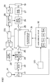
- FIG. 1 is a schematic view of an image recording apparatus according to this invention.
- the image recording apparatus includes a recording drum 11 having a recording medium 10 mounted peripherally thereof, a drum drive motor 13 connected to the recording drum 11 through a shaft 12 for rotating the recording drum 11 about its axis, a rotary encoder 14 for detecting a rotating state of the recording drum 11, a recording head 15 having a laser diode 27, to be described hereinafter, disposed therein, the recording head 15 being meshed with a ball screw 16 to be reciprocable axially of the recording drum 11, a recording head drive motor 17 for reciprocating the recording head 15 by rotating the ball screw 16, a rotary encoder 18 for detecting a rotating state of the ball screw 16, and a calibration sensor 19 disposed laterally of the recording drum 11.
- Fig. 2 is a block diagram showing a principal electrical structure of the image recording apparatus according to this invention.
- the image recording apparatus includes a controller 100 having a CPU as a main component thereof for performing logical operations.
- the controller 100 carries out various operations as described hereinafter.
- the image recording apparatus includes a switching device 25 for switching between a first recording mode for use in recording images on a recording medium 10 with low sensitivity and a second recording mode for use in recording images on a recording medium 10 with high sensitivity.
- the switching device 25 switches between the first recording mode and second recording mode in response to commands from the controller 100.
- the first recording mode is a mode of irradiating the recording medium 10 with a laser beam emitted from the laser diode 27 when an image signal is ON.
- the second recording mode is a mode of irradiating the recording medium 10 with the laser beam emitted from the laser diode 27 when both the image signal and a reference signal are ON.
- a signal of the rotary encoder 14 for detecting a rotating state of the recording drum 11 is multiplied by a PLL circuit 21 to generate a PLL clock signal.
- the PLL clock signal is divided by a frequency divider 22 to generate a dot clock signal.
- Data of an image to be recorded on the recording medium 10 (image data) is stored in an image memory 23.
- An image signal generating circuit 24 generates the image signal based on and timed with the dot clock signal generated by the frequency divider 22.
- the laser diode 27 needs to be blinked on and off in cycles corresponding to the size of one dot which is a minimum unit of an image to be formed on the recording medium.
- a dot sized 10.58 ⁇ m in the primary scanning direction becomes a minimum unit for laser driving.
- the laser beam needs to be blinked on and off in cycles corresponding to time intervals taken to scan the recording medium by approximately 10.58 ⁇ m.
- the frequency divider 22 therefore, generates the dot clock signal having a frequency determined based on a primary scanning speed of the laser beam and a size in the primary scanning direction of one dot.
- the image signal is inputted to a laser driver circuit 26, whereby the laser diode 27 is turned on according to the image signal to record the image on the recording medium 10. That is, in this first recording mode, when the image signal is ON, the laser beam emitted from the laser diode 27 irradiates the recording medium 10.
- a pulse selector circuit 32 selectively generates reference signals having frequencies twice, four times, eight times and 16 times that of the dot clock signal, by dividing the frequency of the PLL clock signal from the PLL circuit 21. Selection of a reference signal is carried out in response to a command from the controller 100.
- Each of the pulse selector circuit 32 and frequency divider 22 has a dividing ratio set such that the reference signal always has a higher frequency than the dot clock signal.
- the reference signal generated by the pulse selector circuit 32 is sent to the pulse exposure control circuit 31.
- the pulse exposure control circuit 31 carries out a digital logic operation to obtain a logical product of the image signal and the reference signal, generates a driving signal for driving the laser diode, and outputs this signal to the laser driver circuit 26.
- the laser driver circuit 26 turns on the laser diode 27 according to the laser diode driving signal, to record the image on the recording medium 10. That is, in the second recording mode, when both the image signal and the reference signal are ON, the laser beam emitted from the laser diode 27 irradiates the recording medium 10.
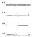
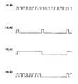
- Figs. 3 through 6 are timing charts showing the above reference signals, dot clock signal, image signal, and the laser diode driving signals in the second recording mode.
- sign A represents the reference signals
- B represents the dot clock signal
- C represents the image signal
- D represents the laser diode driving signals in the second recording mode.
- Figs. 3A through 3D shows a case where the reference signal generated has a frequency 16 times the frequency of the dot clock signal.
- Figs. 4A through 4D shows a case where the reference signal generated has a frequency eight times the frequency of the dot clock signal.
- Figs. 5A through 5D shows a case where the reference signal generated has a frequency four times the frequency of the dot clock signal.
- Figs. 6A through 6D shows a case where the reference signal generated has a frequency twice the frequency of the dot clock signal.
- the laser beam emitted from the laser diode 27 irradiates the recording medium 10. That is, in the first recording mode, the image signal represented by C in each figure is used, as the driving signal for the laser diode 27.
- a comparison between the driving signal for the laser diode 27 in the second recording mode represented by Fig. 6D and the image signal by Fig. 6C shows that the two signals can turn on simultaneously but turn off with time lags.
- the laser beam emitted from the laser diode 27 has a fixed time delay occurring at rise times and after turn-offs. Thus, there is no substantial influence on image recording accuracy.
- the laser beam emitted from the laser diode 27 is inputted to the calibration sensor 19 as necessary. Measurements by the calibration sensor 19 are inputted to a power setting circuit 28 through an AD converter 29. Thus, the output of the laser beam emitted from the laser diode 27 is adjusted to a predetermined value through the laser driver circuit 26.
- This image recording apparatus turns on the laser diode 27 to produce substantially the same output as a rated output in the first recording mode, and to produce an output lower than the rated output in the second recording mode.
- the controller 100 controls the laser driver circuit 26 through the power setting circuit 28 to turn on the laser diode 27 to produce an output 60 to 80%, preferably about 70%, of the rated output.
- the output reduced to 50% or less would change the beam profile of the laser beam emitted from the laser diode 27, which is not desirable.
- this image recording apparatus rotates the recording drum 11 at a relatively slow, first rotating speed in the first recording mode, and at a second rotating speed in the second recording mode faster than the first rotating speed.
- the rotating speed of the recording drum 11 is set to about 100rpm - 300rpm.
- the rotating speed of the recording drum 11 is set to about 700rpm for the second recording mode, thereby reducing a substantial integrated quantity of light to the recording medium 10. This speed adjustment is effected by the controller 100 controlling the drum drive motor 13 and recording head drive motor 17.
- the controller 100 when recording an image on the recording medium 10 with low sensitivity, switches the switching device 25 to the side for performing the first recording mode.
- the controller 100 also transmits a command to the power setting circuit 28 for lighting the laser diode 27 to produce substantially the same output as the rated output.
- the controller 100 controls the drum drive motor 13 and recording head drive motor 17 to set the rotating speed of the recording drum 11 to about 100rpm - 300rpm. As a result, the laser beam applies high energy to the recording medium 10, thereby recording the image properly on the recording medium 10 with low sensitivity.
- the controller 100 switches the switching device 25 to the side for performing the second recording mode.
- the controller 100 also transmits a command to the power setting circuit 28 for lighting the laser diode 27 to produce an output 60 to 80%, preferably about 70%, of the rated output.
- the controller 100 controls the drum drive motor 13 and recording head drive motor 17 to set the rotating speed of the recording drum 11 to about 700rpm.
- the laser beam applies low energy to the recording medium 10, thereby recording the image properly on the recording medium 10 with high sensitivity.
- a reference signal corresponding to the sensitivity and characteristic of the recording medium 10 may be selected for use from among the reference signals having frequencies twice, four times, eight times and 16 times that of the dot clock signal.
- the reference signals having frequencies twice, four times, eight times and 16 times that of the dot clock signal are generated. Too quick a reference signal will have a problem of failing to accommodate the ON/OFF response speed of the laser diode 27.
- the reference signals have frequencies which are integral multiples of the dot clock frequency. It is not absolutely necessary for the frequencies to be integral multiples. However, integral multiples facilitate creation of the reference signals.
- the reference signals used in the foregoing embodiment have frequencies which are integral multiples of the dot clock frequency, and alternate ON and OFF. Instead, the reference signals may repeat ON, OFF and OFF to reduce the substantial integrated quantity of light to one third.
- laser beam irradiation is controlled by directly controlling lighting of the laser diode 27.
- the laser source may always be kept on, with on-off control of the laser beam from this laser source being carried out using an AOM (acoustooptic modulator).
- AOM acoustooptic modulator
Landscapes
- Physics & Mathematics (AREA)
- Engineering & Computer Science (AREA)
- Optics & Photonics (AREA)
- General Engineering & Computer Science (AREA)
- General Physics & Mathematics (AREA)
- Theoretical Computer Science (AREA)
- Exposure And Positioning Against Photoresist Photosensitive Materials (AREA)
- Facsimile Scanning Arrangements (AREA)
- Manufacture Or Reproduction Of Printing Formes (AREA)
- Laser Beam Printer (AREA)
Abstract
Description
- This invention relates to an image recording apparatus for irradiating a recording medium with a laser beam emitted from a laser source, based on image signals created with reference to a dot clock signal corresponding to a resolution and the like of an image to be recorded.
- An image recording apparatus, as described in Japan Patent No.
3544593 - When an image is recorded on various types of recording medium using such an image recording apparatus, the image sometimes cannot be recorded properly due to a difference in sensitivity between the recording mediums.
- In a CTP (computer-to-plate) apparatus for making a printing plate for flexography, for example, an image may be recorded on both a flexographic plate with low sensitivity and an offset printing plate with high sensitivity. When the image is recorded on the offset printing plate by employing a construction that can record the image on the flexographic plate with low sensitivity, the intensity of the laser beam is too strong for the sensitivity of the plate. The laser beam can irradiate a larger area than is required, or damage the surface of the printing plate. Thus, the image cannot be recorded properly.
- To avoid such an inconvenience, it is conceivable to lower the intensity of the laser beam outputted from the laser source by reducing electric current applied to the laser source. However, there is a limit to the intensity of the laser beam reducible by this technique. When the current applied to the laser source is reduced below a certain level, there will arise a problem that the beam profile of the laser beam emitted from the laser source changes.
- It is also conceivable, as described in Japan Patent No.
3544593 - The object of this invention is to provide an image recording apparatus capable of recording images properly both on a recording medium with low sensitivity and on a recording medium with high sensitivity, which is achieved by enabling images to be recorded properly also on the recording medium with low sensitivity.
- The above object is fulfilled, according to this invention, by an image recording apparatus having a laser source for emitting a laser beam that scans a recording medium at a predetermined scanning speed, thereby recording an image having a plurality of dots on the recording medium, the apparatus comprising a device for generating a dot clock signal of a first frequency determined based at least on the scanning speed of the laser beam and a size in a scanning direction of the dots; a device for creating an image signal with reference to the dot clock signal; a reference signal generating device for generating a reference signal of a second frequency higher than the first frequency; and an exposure control device for generating a laser driving signal for driving the laser source by obtaining a logical product of the image signal and the reference signal.
- With this image recording apparatus, an image can be recorded also on a recording medium with low sensitivity by controlling exposure energy (integrated quantity of light).
- In one preferred embodiment, the image recording apparatus can record images properly on both a recording medium with low sensitivity and a recording medium with high sensitivity by enabling an image to be recorded properly also on the recording medium with low sensitivity.
- In another preferred embodiment, the image recording apparatus can record images properly on both a recording medium with low sensitivity and a recording medium with high sensitivity even if an increased difference in sensitivity occurs between the recording mediums.
- Other features and advantages of the invention will be apparent from the following detailed description of the embodiments of the invention.
- For the purpose of illustrating the invention, there are shown in the drawings several forms which are presently preferred, it being understood, however, that the invention is not limited to the precise arrangement and instrumentalities shown.
-
Fig. 1 is a schematic view of an image recording apparatus according to this invention; -
Fig. 2 is a block diagram showing a principal electrical structure of the image recording apparatus according to this invention; -
Fig. 3A is a timing chart showing a reference signal; -
Fig. 3B is a timing chart showing a dot clock signal; -
Fig. 3C is a timing chart showing an image signal; -
Fig. 3D is a timing chart showing a laser diode driving signal in a second recording mode; -
Fig. 4A is a timing chart showing a reference signal; -
Fig. 4B is a timing chart showing the dot clock signal; -
Fig. 4C is a timing chart showing the image signal; -
Fig. 4D is a timing chart showing a laser diode driving signal in the second recording mode; -
Fig. 5A is a timing chart showing a reference signal; -
Fig. 5B is a timing chart showing the dot clock signal; -
Fig. 5C is a timing chart showing the image signal; -
Fig. 5D is a timing chart showing a laser diode driving signal in the second recording mode; -
Fig. 6A is a timing chart showing a reference signal; -
Fig. 6B is a timing chart showing the dot clock signal; -
Fig. 6C is a timing chart showing the image signal; and -
Fig. 6D is a timing chart showing a laser diode driving signal in the second recording mode. - An embodiment of this invention will be described hereinafter with reference to the drawings.
Fig. 1 is a schematic view of an image recording apparatus according to this invention. - The image recording apparatus includes a recording drum 11 having a
recording medium 10 mounted peripherally thereof, adrum drive motor 13 connected to the recording drum 11 through ashaft 12 for rotating the recording drum 11 about its axis, arotary encoder 14 for detecting a rotating state of the recording drum 11, arecording head 15 having alaser diode 27, to be described hereinafter, disposed therein, therecording head 15 being meshed with aball screw 16 to be reciprocable axially of the recording drum 11, a recordinghead drive motor 17 for reciprocating therecording head 15 by rotating theball screw 16, arotary encoder 18 for detecting a rotating state of theball screw 16, and acalibration sensor 19 disposed laterally of the recording drum 11. -
Fig. 2 is a block diagram showing a principal electrical structure of the image recording apparatus according to this invention. - The image recording apparatus includes a
controller 100 having a CPU as a main component thereof for performing logical operations. Thecontroller 100 carries out various operations as described hereinafter. - The image recording apparatus includes a
switching device 25 for switching between a first recording mode for use in recording images on arecording medium 10 with low sensitivity and a second recording mode for use in recording images on arecording medium 10 with high sensitivity. The switchingdevice 25 switches between the first recording mode and second recording mode in response to commands from thecontroller 100. The first recording mode is a mode of irradiating therecording medium 10 with a laser beam emitted from thelaser diode 27 when an image signal is ON. The second recording mode is a mode of irradiating therecording medium 10 with the laser beam emitted from thelaser diode 27 when both the image signal and a reference signal are ON. - A signal of the
rotary encoder 14 for detecting a rotating state of the recording drum 11 is multiplied by aPLL circuit 21 to generate a PLL clock signal. The PLL clock signal is divided by afrequency divider 22 to generate a dot clock signal. Data of an image to be recorded on the recording medium 10 (image data) is stored in animage memory 23. An imagesignal generating circuit 24 generates the image signal based on and timed with the dot clock signal generated by thefrequency divider 22. - The
laser diode 27 needs to be blinked on and off in cycles corresponding to the size of one dot which is a minimum unit of an image to be formed on the recording medium. - When, for example, a recording resolution of 2400dpi (dot per inch) is designated, a dot sized 10.58 µm in the primary scanning direction becomes a minimum unit for laser driving. In this case, the laser beam needs to be blinked on and off in cycles corresponding to time intervals taken to scan the recording medium by approximately 10.58µm. The
frequency divider 22, therefore, generates the dot clock signal having a frequency determined based on a primary scanning speed of the laser beam and a size in the primary scanning direction of one dot. - When the
switching device 25 is switched to a side for performing the first recording mode, the image signal is inputted to alaser driver circuit 26, whereby thelaser diode 27 is turned on according to the image signal to record the image on therecording medium 10. That is, in this first recording mode, when the image signal is ON, the laser beam emitted from thelaser diode 27 irradiates therecording medium 10. - On the other hand, when the
switching device 25 is switched to a side for performing the second recording mode, the image signal is inputted to a pulseexposure control circuit 31. Apulse selector circuit 32 selectively generates reference signals having frequencies twice, four times, eight times and 16 times that of the dot clock signal, by dividing the frequency of the PLL clock signal from thePLL circuit 21. Selection of a reference signal is carried out in response to a command from thecontroller 100. - Each of the
pulse selector circuit 32 andfrequency divider 22 has a dividing ratio set such that the reference signal always has a higher frequency than the dot clock signal. - The reference signal generated by the
pulse selector circuit 32 is sent to the pulseexposure control circuit 31. The pulseexposure control circuit 31 carries out a digital logic operation to obtain a logical product of the image signal and the reference signal, generates a driving signal for driving the laser diode, and outputs this signal to thelaser driver circuit 26. Thelaser driver circuit 26 turns on thelaser diode 27 according to the laser diode driving signal, to record the image on therecording medium 10. That is, in the second recording mode, when both the image signal and the reference signal are ON, the laser beam emitted from thelaser diode 27 irradiates therecording medium 10. -
Figs. 3 through 6 are timing charts showing the above reference signals, dot clock signal, image signal, and the laser diode driving signals in the second recording mode. In these figures, sign A represents the reference signals, B represents the dot clock signal, C represents the image signal, and D represents the laser diode driving signals in the second recording mode.Figs. 3A through 3D shows a case where the reference signal generated has afrequency 16 times the frequency of the dot clock signal.Figs. 4A through 4D shows a case where the reference signal generated has a frequency eight times the frequency of the dot clock signal.Figs. 5A through 5D shows a case where the reference signal generated has a frequency four times the frequency of the dot clock signal.Figs. 6A through 6D shows a case where the reference signal generated has a frequency twice the frequency of the dot clock signal. - In the first recording mode, when the image signal rising synchronously with the dot clock signal is ON, the laser beam emitted from the
laser diode 27 irradiates therecording medium 10. That is, in the first recording mode, the image signal represented by C in each figure is used, as the driving signal for thelaser diode 27. - On the other hand, in the second recording mode, the signal with the logical product of the image signal and reference signal, represented by D in each figure, becomes the driving signal for the
laser diode 27. Therefore, integrated exposure of therecording medium 10 in the second recording mode is half that in the first recording mode. This enables images to be recorded properly also on therecording medium 10 with high sensitivity. - When the reference signal having about twice the frequency of the dot clock signal as shown in
Fig. 6 is used, a comparison between the driving signal for thelaser diode 27 in the second recording mode represented byFig. 6D and the image signal byFig. 6C (i.e. the driving signal for thelaser diode 27 in the first recording mode) shows that the two signals can turn on simultaneously but turn off with time lags. However, the laser beam emitted from thelaser diode 27 has a fixed time delay occurring at rise times and after turn-offs. Thus, there is no substantial influence on image recording accuracy. - Referring to
Fig. 2 again, the laser beam emitted from thelaser diode 27 is inputted to thecalibration sensor 19 as necessary. Measurements by thecalibration sensor 19 are inputted to apower setting circuit 28 through anAD converter 29. Thus, the output of the laser beam emitted from thelaser diode 27 is adjusted to a predetermined value through thelaser driver circuit 26. - This image recording apparatus turns on the
laser diode 27 to produce substantially the same output as a rated output in the first recording mode, and to produce an output lower than the rated output in the second recording mode. Specifically, in the second recording mode, thecontroller 100 controls thelaser driver circuit 26 through thepower setting circuit 28 to turn on thelaser diode 27 to produce an output 60 to 80%, preferably about 70%, of the rated output. The output reduced to 50% or less would change the beam profile of the laser beam emitted from thelaser diode 27, which is not desirable. - Further, this image recording apparatus rotates the recording drum 11 at a relatively slow, first rotating speed in the first recording mode, and at a second rotating speed in the second recording mode faster than the first rotating speed. Specifically, for the first recording mode, the rotating speed of the recording drum 11 is set to about 100rpm - 300rpm. On the other hand, the rotating speed of the recording drum 11 is set to about 700rpm for the second recording mode, thereby reducing a substantial integrated quantity of light to the
recording medium 10. This speed adjustment is effected by thecontroller 100 controlling thedrum drive motor 13 and recordinghead drive motor 17. - In the image recording apparatus having the above construction, when recording an image on the
recording medium 10 with low sensitivity, thecontroller 100 switches theswitching device 25 to the side for performing the first recording mode. Thecontroller 100 also transmits a command to thepower setting circuit 28 for lighting thelaser diode 27 to produce substantially the same output as the rated output. Further, thecontroller 100 controls thedrum drive motor 13 and recordinghead drive motor 17 to set the rotating speed of the recording drum 11 to about 100rpm - 300rpm. As a result, the laser beam applies high energy to therecording medium 10, thereby recording the image properly on therecording medium 10 with low sensitivity. - On the other hand, when recording an image on the
recording medium 10 with high sensitivity, thecontroller 100 switches theswitching device 25 to the side for performing the second recording mode. Thecontroller 100 also transmits a command to thepower setting circuit 28 for lighting thelaser diode 27 to produce an output 60 to 80%, preferably about 70%, of the rated output. Further, thecontroller 100 controls thedrum drive motor 13 and recordinghead drive motor 17 to set the rotating speed of the recording drum 11 to about 700rpm. As a result, the laser beam applies low energy to therecording medium 10, thereby recording the image properly on therecording medium 10 with high sensitivity. - For the second recording mode, a reference signal corresponding to the sensitivity and characteristic of the
recording medium 10 may be selected for use from among the reference signals having frequencies twice, four times, eight times and 16 times that of the dot clock signal. - In the foregoing embodiment, the reference signals having frequencies twice, four times, eight times and 16 times that of the dot clock signal are generated. Too quick a reference signal will have a problem of failing to accommodate the ON/OFF response speed of the
laser diode 27. In this embodiment, the reference signals have frequencies which are integral multiples of the dot clock frequency. It is not absolutely necessary for the frequencies to be integral multiples. However, integral multiples facilitate creation of the reference signals. - The reference signals used in the foregoing embodiment have frequencies which are integral multiples of the dot clock frequency, and alternate ON and OFF. Instead, the reference signals may repeat ON, OFF and OFF to reduce the substantial integrated quantity of light to one third.
- In the foregoing embodiment, laser beam irradiation is controlled by directly controlling lighting of the
laser diode 27. Alternatively, for example, the laser source may always be kept on, with on-off control of the laser beam from this laser source being carried out using an AOM (acoustooptic modulator).
Claims (7)
- An image recording apparatus having a laser source (27) for emitting a laser beam that scans a recording medium (10) at a predetermined scanning speed, thereby recording an image having a plurality of dots on the recording medium (10), said apparatus comprising:a device for generating a dot clock signal (22) of a first frequency determined based at least on the scanning speed of said laser beam and a size in a scanning direction of said dots;a device for creating an image signal (24) with reference to said dot clock signal;a reference signal generating device (32) for generating a reference signal of a second frequency higher than said first frequency; andan exposure control device (31) for generating a laser driving signal for driving said laser source (27) by obtaining a logical product of said image signal and said reference signal.
- An image recording apparatus as defined in claim 1, wherein:said recording medium (10) is mounted peripherally of a recording drum (11) rotatable about an axis thereof andsaid dot clock signal and said reference signal are created with reference to a signal from a rotary encoder connected to said recording drum (11).
- An image recording apparatus as defined in claim 1,
said exposure control device (31) is arranged to switch between a first recording mode for using said image signal as said laser driving signal, and a second recording mode for generating said laser driving signal by obtaining a logical product of said image signal and said reference signal. - An image recording apparatus as defined in claim 3, wherein:in said first recording mode, said recording drum (11) is rotated at a first rotating speed; andin said second recording mode, said recording drum (11) is rotated at a second rotating speed faster than said first rotating speed.
- An image recording apparatus as defined in claim 4, wherein:in said first recording mode, said laser source (27) is lit to produce substantially the same output as a rated output; andin said second recording mode, said laser source (27) is lit to produce an output lower than said rated output.
- An image recording apparatus as defined in claim 5, wherein said reference signal generating device (32) is arranged to generate a reference signal of a frequency which is n times the frequency of the dot clock signal, where n is an integer two or more.
- An image recording apparatus as defined in claim 6, said reference signal generating device (32) is capable of setting a plurality of values as said n.
Applications Claiming Priority (1)
| Application Number | Priority Date | Filing Date | Title |
|---|---|---|---|
| JP2007045509A JP4948203B2 (en) | 2007-02-26 | 2007-02-26 | Image recording device |
Publications (3)
| Publication Number | Publication Date |
|---|---|
| EP1962228A2 true EP1962228A2 (en) | 2008-08-27 |
| EP1962228A3 EP1962228A3 (en) | 2013-08-28 |
| EP1962228B1 EP1962228B1 (en) | 2017-01-18 |
Family
ID=39469345
Family Applications (1)
| Application Number | Title | Priority Date | Filing Date |
|---|---|---|---|
| EP08002294.0A Not-in-force EP1962228B1 (en) | 2007-02-26 | 2008-02-07 | Image recording apparatus |
Country Status (3)
| Country | Link |
|---|---|
| US (1) | US7868908B2 (en) |
| EP (1) | EP1962228B1 (en) |
| JP (1) | JP4948203B2 (en) |
Families Citing this family (1)
| Publication number | Priority date | Publication date | Assignee | Title |
|---|---|---|---|---|
| JP6818479B2 (en) * | 2016-09-16 | 2021-01-20 | デクセリアルズ株式会社 | Master manufacturing method |
Citations (1)
| Publication number | Priority date | Publication date | Assignee | Title |
|---|---|---|---|---|
| JP3544593B2 (en) | 1995-12-11 | 2004-07-21 | 大日本スクリーン製造株式会社 | Image recording apparatus and adjustment method thereof |
Family Cites Families (9)
| Publication number | Priority date | Publication date | Assignee | Title |
|---|---|---|---|---|
| JPS6475242A (en) * | 1987-09-16 | 1989-03-20 | Fuji Photo Film Co Ltd | Light beam recording device |
| US5258776A (en) * | 1991-08-23 | 1993-11-02 | Eastman Kodak Company | High resolution thermal printers including a print head with heat producing elements disposed at an acute angle |
| JP2002072119A (en) * | 2000-09-01 | 2002-03-12 | Fuji Photo Film Co Ltd | Light beam scanning device |
| US6731317B2 (en) * | 2001-03-14 | 2004-05-04 | Ricoh Company, Ltd. | Pulse modulation signal generation circuit, and semiconductor laser modulation device, optical scanning device and image formation device using the same |
| JP2003011419A (en) * | 2001-06-29 | 2003-01-15 | Dainippon Screen Mfg Co Ltd | Image recorder |
| WO2003033271A1 (en) * | 2001-10-12 | 2003-04-24 | Dainippon Screen Mfg. Co., Ltd. | Image recording apparatus |
| JP4593884B2 (en) * | 2002-05-10 | 2010-12-08 | キヤノン株式会社 | Laser scanning control device |
| US7369148B2 (en) * | 2003-03-11 | 2008-05-06 | Canon Kabushiki Kaisha | Frequency modulation apparatus and frequency modulation method |
| JP4065529B2 (en) * | 2003-03-11 | 2008-03-26 | キヤノン株式会社 | Frequency modulator |
-
2007
- 2007-02-26 JP JP2007045509A patent/JP4948203B2/en not_active Expired - Fee Related
-
2008
- 2008-02-07 EP EP08002294.0A patent/EP1962228B1/en not_active Not-in-force
- 2008-02-26 US US12/071,738 patent/US7868908B2/en not_active Expired - Fee Related
Patent Citations (1)
| Publication number | Priority date | Publication date | Assignee | Title |
|---|---|---|---|---|
| JP3544593B2 (en) | 1995-12-11 | 2004-07-21 | 大日本スクリーン製造株式会社 | Image recording apparatus and adjustment method thereof |
Also Published As
| Publication number | Publication date |
|---|---|
| JP4948203B2 (en) | 2012-06-06 |
| JP2008209612A (en) | 2008-09-11 |
| US20080205457A1 (en) | 2008-08-28 |
| US7868908B2 (en) | 2011-01-11 |
| EP1962228A3 (en) | 2013-08-28 |
| EP1962228B1 (en) | 2017-01-18 |
Similar Documents
| Publication | Publication Date | Title |
|---|---|---|
| US5327167A (en) | Printing cylinder engraving | |
| JP4703222B2 (en) | Printing plate making equipment | |
| JP2006095931A (en) | Plate making method and plate making apparatus for printing plate | |
| JP4593884B2 (en) | Laser scanning control device | |
| US6364443B1 (en) | Thermal printer and recording method thereof | |
| EP1642712B1 (en) | Platemaking method and platemaking apparatus | |
| US7868908B2 (en) | Image recording apparatus having a laser source | |
| JP4182515B2 (en) | Pattern drawing device | |
| JPH10166649A (en) | APC control pull-in method and image forming apparatus | |
| JP2006224481A (en) | Platemaking equipment of printing plate | |
| CN108628389B (en) | Clock generation device, clock generation method, and image recording device | |
| JP5063012B2 (en) | Optical scanning apparatus and image forming apparatus | |
| JP2653782B2 (en) | Laser drawing equipment | |
| US8320028B2 (en) | Optical scanning apparatus | |
| US20050030500A1 (en) | Apparatus for forming pattern | |
| JP2017193122A (en) | Clock generation device and image formation apparatus | |
| JP5397723B2 (en) | Optical scanning device | |
| JP2004351512A (en) | Laser marking device | |
| US6784913B2 (en) | Exposure recording apparatus for recording a two-dimensional image | |
| JP2007152731A (en) | Image forming apparatus | |
| JP2004333618A (en) | Pattern drawing device | |
| JP2001213002A (en) | Image recorder | |
| JP2006227261A (en) | Platemaking apparatus for printing plate | |
| JPH09240052A (en) | Image forming device | |
| JPH04318877A (en) | Image forming device |
Legal Events
| Date | Code | Title | Description |
|---|---|---|---|
| PUAI | Public reference made under article 153(3) epc to a published international application that has entered the european phase |
Free format text: ORIGINAL CODE: 0009012 |
|
| AK | Designated contracting states |
Kind code of ref document: A2 Designated state(s): AT BE BG CH CY CZ DE DK EE ES FI FR GB GR HR HU IE IS IT LI LT LU LV MC MT NL NO PL PT RO SE SI SK TR |
|
| AX | Request for extension of the european patent |
Extension state: AL BA MK RS |
|
| PUAL | Search report despatched |
Free format text: ORIGINAL CODE: 0009013 |
|
| AK | Designated contracting states |
Kind code of ref document: A3 Designated state(s): AT BE BG CH CY CZ DE DK EE ES FI FR GB GR HR HU IE IS IT LI LT LU LV MC MT NL NO PL PT RO SE SI SK TR |
|
| AX | Request for extension of the european patent |
Extension state: AL BA MK RS |
|
| RIC1 | Information provided on ipc code assigned before grant |
Ipc: G06K 15/12 20060101AFI20130725BHEP Ipc: B41J 2/47 20060101ALI20130725BHEP |
|
| 17P | Request for examination filed |
Effective date: 20140227 |
|
| AKX | Designation fees paid |
Designated state(s): AT BE BG CH CY CZ DE DK EE ES FI FR GB GR HR HU IE IS IT LI LT LU LV MC MT NL NO PL PT RO SE SI SK TR |
|
| RAP1 | Party data changed (applicant data changed or rights of an application transferred) |
Owner name: SCREEN HOLDINGS CO., LTD. |
|
| 17Q | First examination report despatched |
Effective date: 20160523 |
|
| GRAP | Despatch of communication of intention to grant a patent |
Free format text: ORIGINAL CODE: EPIDOSNIGR1 |
|
| RIC1 | Information provided on ipc code assigned before grant |
Ipc: B41J 2/47 20060101ALI20161024BHEP Ipc: G06K 15/12 20060101AFI20161024BHEP Ipc: B41J 13/22 20060101ALI20161024BHEP |
|
| INTG | Intention to grant announced |
Effective date: 20161108 |
|
| GRAS | Grant fee paid |
Free format text: ORIGINAL CODE: EPIDOSNIGR3 |
|
| GRAA | (expected) grant |
Free format text: ORIGINAL CODE: 0009210 |
|
| AK | Designated contracting states |
Kind code of ref document: B1 Designated state(s): AT BE BG CH CY CZ DE DK EE ES FI FR GB GR HR HU IE IS IT LI LT LU LV MC MT NL NO PL PT RO SE SI SK TR |
|
| REG | Reference to a national code |
Ref country code: GB Ref legal event code: FG4D |
|
| REG | Reference to a national code |
Ref country code: CH Ref legal event code: EP |
|
| REG | Reference to a national code |
Ref country code: AT Ref legal event code: REF Ref document number: 863279 Country of ref document: AT Kind code of ref document: T Effective date: 20170215 |
|
| REG | Reference to a national code |
Ref country code: IE Ref legal event code: FG4D |
|
| REG | Reference to a national code |
Ref country code: FR Ref legal event code: PLFP Year of fee payment: 10 |
|
| REG | Reference to a national code |
Ref country code: DE Ref legal event code: R096 Ref document number: 602008048433 Country of ref document: DE |
|
| REG | Reference to a national code |
Ref country code: NL Ref legal event code: MP Effective date: 20170118 |
|
| REG | Reference to a national code |
Ref country code: LT Ref legal event code: MG4D |
|
| PG25 | Lapsed in a contracting state [announced via postgrant information from national office to epo] |
Ref country code: BE Free format text: LAPSE BECAUSE OF NON-PAYMENT OF DUE FEES Effective date: 20170228 |
|
| REG | Reference to a national code |
Ref country code: AT Ref legal event code: MK05 Ref document number: 863279 Country of ref document: AT Kind code of ref document: T Effective date: 20170118 |
|
| PG25 | Lapsed in a contracting state [announced via postgrant information from national office to epo] |
Ref country code: NL Free format text: LAPSE BECAUSE OF FAILURE TO SUBMIT A TRANSLATION OF THE DESCRIPTION OR TO PAY THE FEE WITHIN THE PRESCRIBED TIME-LIMIT Effective date: 20170118 |
|
| PG25 | Lapsed in a contracting state [announced via postgrant information from national office to epo] |
Ref country code: NO Free format text: LAPSE BECAUSE OF FAILURE TO SUBMIT A TRANSLATION OF THE DESCRIPTION OR TO PAY THE FEE WITHIN THE PRESCRIBED TIME-LIMIT Effective date: 20170418 Ref country code: HR Free format text: LAPSE BECAUSE OF FAILURE TO SUBMIT A TRANSLATION OF THE DESCRIPTION OR TO PAY THE FEE WITHIN THE PRESCRIBED TIME-LIMIT Effective date: 20170118 Ref country code: IS Free format text: LAPSE BECAUSE OF FAILURE TO SUBMIT A TRANSLATION OF THE DESCRIPTION OR TO PAY THE FEE WITHIN THE PRESCRIBED TIME-LIMIT Effective date: 20170518 Ref country code: FI Free format text: LAPSE BECAUSE OF FAILURE TO SUBMIT A TRANSLATION OF THE DESCRIPTION OR TO PAY THE FEE WITHIN THE PRESCRIBED TIME-LIMIT Effective date: 20170118 Ref country code: GR Free format text: LAPSE BECAUSE OF FAILURE TO SUBMIT A TRANSLATION OF THE DESCRIPTION OR TO PAY THE FEE WITHIN THE PRESCRIBED TIME-LIMIT Effective date: 20170419 Ref country code: LT Free format text: LAPSE BECAUSE OF FAILURE TO SUBMIT A TRANSLATION OF THE DESCRIPTION OR TO PAY THE FEE WITHIN THE PRESCRIBED TIME-LIMIT Effective date: 20170118 |
|
| PG25 | Lapsed in a contracting state [announced via postgrant information from national office to epo] |
Ref country code: PL Free format text: LAPSE BECAUSE OF FAILURE TO SUBMIT A TRANSLATION OF THE DESCRIPTION OR TO PAY THE FEE WITHIN THE PRESCRIBED TIME-LIMIT Effective date: 20170118 Ref country code: BG Free format text: LAPSE BECAUSE OF FAILURE TO SUBMIT A TRANSLATION OF THE DESCRIPTION OR TO PAY THE FEE WITHIN THE PRESCRIBED TIME-LIMIT Effective date: 20170418 Ref country code: AT Free format text: LAPSE BECAUSE OF FAILURE TO SUBMIT A TRANSLATION OF THE DESCRIPTION OR TO PAY THE FEE WITHIN THE PRESCRIBED TIME-LIMIT Effective date: 20170118 Ref country code: SE Free format text: LAPSE BECAUSE OF FAILURE TO SUBMIT A TRANSLATION OF THE DESCRIPTION OR TO PAY THE FEE WITHIN THE PRESCRIBED TIME-LIMIT Effective date: 20170118 Ref country code: LV Free format text: LAPSE BECAUSE OF FAILURE TO SUBMIT A TRANSLATION OF THE DESCRIPTION OR TO PAY THE FEE WITHIN THE PRESCRIBED TIME-LIMIT Effective date: 20170118 Ref country code: PT Free format text: LAPSE BECAUSE OF FAILURE TO SUBMIT A TRANSLATION OF THE DESCRIPTION OR TO PAY THE FEE WITHIN THE PRESCRIBED TIME-LIMIT Effective date: 20170518 Ref country code: ES Free format text: LAPSE BECAUSE OF FAILURE TO SUBMIT A TRANSLATION OF THE DESCRIPTION OR TO PAY THE FEE WITHIN THE PRESCRIBED TIME-LIMIT Effective date: 20170118 |
|
| REG | Reference to a national code |
Ref country code: CH Ref legal event code: PL |
|
| REG | Reference to a national code |
Ref country code: DE Ref legal event code: R097 Ref document number: 602008048433 Country of ref document: DE |
|
| PG25 | Lapsed in a contracting state [announced via postgrant information from national office to epo] |
Ref country code: LI Free format text: LAPSE BECAUSE OF NON-PAYMENT OF DUE FEES Effective date: 20170228 Ref country code: CZ Free format text: LAPSE BECAUSE OF FAILURE TO SUBMIT A TRANSLATION OF THE DESCRIPTION OR TO PAY THE FEE WITHIN THE PRESCRIBED TIME-LIMIT Effective date: 20170118 Ref country code: IT Free format text: LAPSE BECAUSE OF FAILURE TO SUBMIT A TRANSLATION OF THE DESCRIPTION OR TO PAY THE FEE WITHIN THE PRESCRIBED TIME-LIMIT Effective date: 20170118 Ref country code: EE Free format text: LAPSE BECAUSE OF FAILURE TO SUBMIT A TRANSLATION OF THE DESCRIPTION OR TO PAY THE FEE WITHIN THE PRESCRIBED TIME-LIMIT Effective date: 20170118 Ref country code: SK Free format text: LAPSE BECAUSE OF FAILURE TO SUBMIT A TRANSLATION OF THE DESCRIPTION OR TO PAY THE FEE WITHIN THE PRESCRIBED TIME-LIMIT Effective date: 20170118 Ref country code: CH Free format text: LAPSE BECAUSE OF NON-PAYMENT OF DUE FEES Effective date: 20170228 Ref country code: RO Free format text: LAPSE BECAUSE OF FAILURE TO SUBMIT A TRANSLATION OF THE DESCRIPTION OR TO PAY THE FEE WITHIN THE PRESCRIBED TIME-LIMIT Effective date: 20170118 |
|
| PLBE | No opposition filed within time limit |
Free format text: ORIGINAL CODE: 0009261 |
|
| STAA | Information on the status of an ep patent application or granted ep patent |
Free format text: STATUS: NO OPPOSITION FILED WITHIN TIME LIMIT |
|
| REG | Reference to a national code |
Ref country code: IE Ref legal event code: MM4A |
|
| PG25 | Lapsed in a contracting state [announced via postgrant information from national office to epo] |
Ref country code: MC Free format text: LAPSE BECAUSE OF FAILURE TO SUBMIT A TRANSLATION OF THE DESCRIPTION OR TO PAY THE FEE WITHIN THE PRESCRIBED TIME-LIMIT Effective date: 20170118 Ref country code: DK Free format text: LAPSE BECAUSE OF FAILURE TO SUBMIT A TRANSLATION OF THE DESCRIPTION OR TO PAY THE FEE WITHIN THE PRESCRIBED TIME-LIMIT Effective date: 20170118 |
|
| 26N | No opposition filed |
Effective date: 20171019 |
|
| PG25 | Lapsed in a contracting state [announced via postgrant information from national office to epo] |
Ref country code: LU Free format text: LAPSE BECAUSE OF NON-PAYMENT OF DUE FEES Effective date: 20170207 |
|
| REG | Reference to a national code |
Ref country code: FR Ref legal event code: PLFP Year of fee payment: 11 |
|
| REG | Reference to a national code |
Ref country code: BE Ref legal event code: MM Effective date: 20170228 |
|
| PG25 | Lapsed in a contracting state [announced via postgrant information from national office to epo] |
Ref country code: SI Free format text: LAPSE BECAUSE OF FAILURE TO SUBMIT A TRANSLATION OF THE DESCRIPTION OR TO PAY THE FEE WITHIN THE PRESCRIBED TIME-LIMIT Effective date: 20170118 Ref country code: IE Free format text: LAPSE BECAUSE OF NON-PAYMENT OF DUE FEES Effective date: 20170207 |
|
| PG25 | Lapsed in a contracting state [announced via postgrant information from national office to epo] |
Ref country code: MT Free format text: LAPSE BECAUSE OF NON-PAYMENT OF DUE FEES Effective date: 20170207 |
|
| PG25 | Lapsed in a contracting state [announced via postgrant information from national office to epo] |
Ref country code: HU Free format text: LAPSE BECAUSE OF FAILURE TO SUBMIT A TRANSLATION OF THE DESCRIPTION OR TO PAY THE FEE WITHIN THE PRESCRIBED TIME-LIMIT; INVALID AB INITIO Effective date: 20080207 |
|
| PG25 | Lapsed in a contracting state [announced via postgrant information from national office to epo] |
Ref country code: CY Free format text: LAPSE BECAUSE OF NON-PAYMENT OF DUE FEES Effective date: 20170118 |
|
| PG25 | Lapsed in a contracting state [announced via postgrant information from national office to epo] |
Ref country code: TR Free format text: LAPSE BECAUSE OF FAILURE TO SUBMIT A TRANSLATION OF THE DESCRIPTION OR TO PAY THE FEE WITHIN THE PRESCRIBED TIME-LIMIT Effective date: 20170118 |
|
| PGFP | Annual fee paid to national office [announced via postgrant information from national office to epo] |
Ref country code: GB Payment date: 20211231 Year of fee payment: 15 |
|
| PGFP | Annual fee paid to national office [announced via postgrant information from national office to epo] |
Ref country code: DE Payment date: 20211230 Year of fee payment: 15 |
|
| PGFP | Annual fee paid to national office [announced via postgrant information from national office to epo] |
Ref country code: FR Payment date: 20220118 Year of fee payment: 15 |
|
| P01 | Opt-out of the competence of the unified patent court (upc) registered |
Effective date: 20230515 |
|
| REG | Reference to a national code |
Ref country code: DE Ref legal event code: R119 Ref document number: 602008048433 Country of ref document: DE |
|
| GBPC | Gb: european patent ceased through non-payment of renewal fee |
Effective date: 20230207 |
|
| PG25 | Lapsed in a contracting state [announced via postgrant information from national office to epo] |
Ref country code: GB Free format text: LAPSE BECAUSE OF NON-PAYMENT OF DUE FEES Effective date: 20230207 |
|
| PG25 | Lapsed in a contracting state [announced via postgrant information from national office to epo] |
Ref country code: GB Free format text: LAPSE BECAUSE OF NON-PAYMENT OF DUE FEES Effective date: 20230207 Ref country code: FR Free format text: LAPSE BECAUSE OF NON-PAYMENT OF DUE FEES Effective date: 20230228 Ref country code: DE Free format text: LAPSE BECAUSE OF NON-PAYMENT OF DUE FEES Effective date: 20230901 |