EP1962079A1 - Système et procédé destinés à la tomographie de cohérence optique - Google Patents
Système et procédé destinés à la tomographie de cohérence optique Download PDFInfo
- Publication number
- EP1962079A1 EP1962079A1 EP07102821A EP07102821A EP1962079A1 EP 1962079 A1 EP1962079 A1 EP 1962079A1 EP 07102821 A EP07102821 A EP 07102821A EP 07102821 A EP07102821 A EP 07102821A EP 1962079 A1 EP1962079 A1 EP 1962079A1
- Authority
- EP
- European Patent Office
- Prior art keywords
- detector
- light
- sample
- interferometer
- frequency
- Prior art date
- Legal status (The legal status is an assumption and is not a legal conclusion. Google has not performed a legal analysis and makes no representation as to the accuracy of the status listed.)
- Granted
Links
Images


Classifications
-
- G—PHYSICS
- G01—MEASURING; TESTING
- G01B—MEASURING LENGTH, THICKNESS OR SIMILAR LINEAR DIMENSIONS; MEASURING ANGLES; MEASURING AREAS; MEASURING IRREGULARITIES OF SURFACES OR CONTOURS
- G01B9/00—Measuring instruments characterised by the use of optical techniques
- G01B9/02—Interferometers
- G01B9/02001—Interferometers characterised by controlling or generating intrinsic radiation properties
- G01B9/02012—Interferometers characterised by controlling or generating intrinsic radiation properties using temporal intensity variation
-
- A—HUMAN NECESSITIES
- A61—MEDICAL OR VETERINARY SCIENCE; HYGIENE
- A61B—DIAGNOSIS; SURGERY; IDENTIFICATION
- A61B5/00—Measuring for diagnostic purposes; Identification of persons
- A61B5/0059—Measuring for diagnostic purposes; Identification of persons using light, e.g. diagnosis by transillumination, diascopy, fluorescence
- A61B5/0062—Arrangements for scanning
- A61B5/0066—Optical coherence imaging
-
- A—HUMAN NECESSITIES
- A61—MEDICAL OR VETERINARY SCIENCE; HYGIENE
- A61B—DIAGNOSIS; SURGERY; IDENTIFICATION
- A61B5/00—Measuring for diagnostic purposes; Identification of persons
- A61B5/0059—Measuring for diagnostic purposes; Identification of persons using light, e.g. diagnosis by transillumination, diascopy, fluorescence
- A61B5/0073—Measuring for diagnostic purposes; Identification of persons using light, e.g. diagnosis by transillumination, diascopy, fluorescence by tomography, i.e. reconstruction of 3D images from 2D projections
-
- G—PHYSICS
- G01—MEASURING; TESTING
- G01B—MEASURING LENGTH, THICKNESS OR SIMILAR LINEAR DIMENSIONS; MEASURING ANGLES; MEASURING AREAS; MEASURING IRREGULARITIES OF SURFACES OR CONTOURS
- G01B9/00—Measuring instruments characterised by the use of optical techniques
- G01B9/02—Interferometers
- G01B9/02001—Interferometers characterised by controlling or generating intrinsic radiation properties
- G01B9/02002—Interferometers characterised by controlling or generating intrinsic radiation properties using two or more frequencies
-
- G—PHYSICS
- G01—MEASURING; TESTING
- G01B—MEASURING LENGTH, THICKNESS OR SIMILAR LINEAR DIMENSIONS; MEASURING ANGLES; MEASURING AREAS; MEASURING IRREGULARITIES OF SURFACES OR CONTOURS
- G01B9/00—Measuring instruments characterised by the use of optical techniques
- G01B9/02—Interferometers
- G01B9/02055—Reduction or prevention of errors; Testing; Calibration
- G01B9/02062—Active error reduction, i.e. varying with time
- G01B9/02063—Active error reduction, i.e. varying with time by particular alignment of focus position, e.g. dynamic focussing in optical coherence tomography
-
- G—PHYSICS
- G01—MEASURING; TESTING
- G01B—MEASURING LENGTH, THICKNESS OR SIMILAR LINEAR DIMENSIONS; MEASURING ANGLES; MEASURING AREAS; MEASURING IRREGULARITIES OF SURFACES OR CONTOURS
- G01B9/00—Measuring instruments characterised by the use of optical techniques
- G01B9/02—Interferometers
- G01B9/02055—Reduction or prevention of errors; Testing; Calibration
- G01B9/0207—Error reduction by correction of the measurement signal based on independently determined error sources, e.g. using a reference interferometer
- G01B9/02072—Error reduction by correction of the measurement signal based on independently determined error sources, e.g. using a reference interferometer by calibration or testing of interferometer
-
- G—PHYSICS
- G01—MEASURING; TESTING
- G01B—MEASURING LENGTH, THICKNESS OR SIMILAR LINEAR DIMENSIONS; MEASURING ANGLES; MEASURING AREAS; MEASURING IRREGULARITIES OF SURFACES OR CONTOURS
- G01B9/00—Measuring instruments characterised by the use of optical techniques
- G01B9/02—Interferometers
- G01B9/0209—Low-coherence interferometers
- G01B9/02091—Tomographic interferometers, e.g. based on optical coherence
-
- G—PHYSICS
- G01—MEASURING; TESTING
- G01N—INVESTIGATING OR ANALYSING MATERIALS BY DETERMINING THEIR CHEMICAL OR PHYSICAL PROPERTIES
- G01N21/00—Investigating or analysing materials by the use of optical means, i.e. using sub-millimetre waves, infrared, visible or ultraviolet light
- G01N21/17—Systems in which incident light is modified in accordance with the properties of the material investigated
- G01N21/47—Scattering, i.e. diffuse reflection
- G01N21/4795—Scattering, i.e. diffuse reflection spatially resolved investigating of object in scattering medium
Definitions
- the application relates to a system and to a corresponding method for optical coherence tomography according to the preamble of claims 1 and 16, respectively.
- OCT optical coherence tomography
- OCT optical coherence tomography
- biological tissue Due to its light-scattering properties, biological tissue is particularly suitable for the diagnostic examination by OCT. Since OCT operates with relatively low light intensities and the wavelengths of the light used are mostly in the near infrared range (750 nm to 1350 nm), in contrast to ionizing X-ray diagnostics for biological tissue, it does not represent a radiation load. It is thus of particular importance for medicine and roughly comparable to ultrasound diagnostics. Instead of sound, broadband light, which has a very short coherence length, is used in OCT. The transit times of the light reflected at different boundary layers in the sample are detected by means of an interferometer.
- OCT optical coherence tomography
- the invention is based on the idea of temporally modulating the sensitivity of the detector system.
- the light reflected from the specimen and incident on the detector is superimposed on the modulated sensitivity of the detector system, so that the detector will interfere with the detection of the detector striking the detector Interference pattern generates a low-frequency beat signal instead of a high-frequency interference signal having a plurality of periods, which has significantly fewer periods than the high-frequency interference signal.
- significantly fewer sampling times per time unit are required than when detecting the high-frequency interference signal without the inventive modulation of the sensitivity of the detector system.
- f M ⁇ f D 2 ⁇ V / ⁇ 0 .
- the mean wavelength of the light coupled into the interferometer is typically in the infrared spectral range, preferably between 750 and 1350 nm.
- the average wavelength of the light is preferably in a spectral range in which the light source has an intensity maximum.
- the average wavelength is given by an average of all the wavelengths emitted by the light source.
- the velocity v is given by the temporal change of the optical distance of the reflector to the beam splitter.
- the optical distance of the reflector to the beam splitter is given by the spatial distance of the reflector to the beam splitter, which is multiplied by the refractive index of the medium located between the reflector and the beam splitter.
- the interferometer as so-called. Free-jet interferometer in which there is air or vacuum between the reflector and the beam splitter and the refractive index is approximately equal to 1, the optical distance of the reflector and the optical path, by which the optical distance changes becomes identical to its spatial distance or spatial path.
- the change in the optical distance of the reflector is realized in this case by a movement of the reflector around a spatial path.
- a light-conducting element in particular an optical fiber, be provided whose optical length is selectively changed by an optical path.
- optical fibers are also referred to as fiber stretcher.
- the optical distance and the optical path by which the optical distance is changed by the product of the spatial distance or distance by which the distance is changed, and the refractive index of the light guide, which is typically in the range around 1.5, given.
- the modulation frequency at which the sensitivity of the detector system is modulated is up to 40% greater or less than the Doppler frequency, so that for the modulation frequency f M : 1.2 ⁇ v / ⁇ 0 ⁇ f M ⁇ 2.8 ⁇ V / ⁇ 0 .
- modulating the sensitivity of the detector system with a modulation frequency lying in this frequency range ensures that the number of periods of the beat signal is sufficiently small and thus the times for the detection of the interference signals are very short.
- the detector has a maximum sampling rate, which indicates the maximum possible number of sampling times per unit of time when detecting the light striking the detector, and the maximum Sample rate of the frequency of the beat signal or an integral multiple of the frequency of the beat signal corresponds. In this way, a particularly fast and efficient sampling of the beat signal is ensured.
- a further embodiment of the embodiment described above provides that the frequency of the beat signal, which depends on the Doppler frequency and the modulation frequency, is set by specifying the Doppler frequency and / or the modulation frequency.
- the specification of the Doppler frequency is preferably carried out by specifying the speed of change of the optical distance between the reflector and the first spectral divider.
- the modulation frequency corresponds to the maximum sampling rate of the detector or to an integral multiple of the modulation frequency.
- the maximum sampling rate of the detector is given by the reciprocal of the minimum frame time of the detector, which is composed of the minimum detection time, which is at least necessary in the detection of the light striking the detector in the range of a sampling time, and minimum dead time, which elapses until, after the detection of the light in the range of the sampling time, the light in the range of the next sampling time can be detected.
- the maximum sampling rate of the detector, the frequency of the beat signal or the modulation frequency are tuned to one another in accordance with the invention, in this embodiment, a tuning of the frequency of the beat signal or the modulation frequency on the one hand and the detector properties on the other hand allows.
- the sensitivity of the detector system is modulated sinusoidally or rectangularly. Both alternatives represent particularly simple possibilities of sensitivity modulation.
- the detector has one or more detector elements which have a sensitivity to the light reflected by the sample and striking the detector elements.
- the sensitivity of the detector elements for the light received by the sample is modulated in the manner described above. This represents an easy-to-implement form of modulation of the sensitivity of the detector system.
- the sensitivity of all detector elements of the detector is modulated with the same modulation frequency and the same phase position of the modulation.
- interference signals over the entire detector surface are detected with sufficiently high speed and reliability.
- the sensitivity of the detector system at different lateral points to the respective frequency or phase angle of the interference signal to be detected can be adjusted individually.
- At least one integrator is provided for the integration of currents which are caused by the detection of the light reflected from the sample by the detector elements.
- the integration of the currents through the integrator is modulated at the modulation frequency. The sensitivity of the detector can thereby be modulated particularly simply and precisely.
- the detector system comprises at least one optical element which has a transmittance for the light reflected from the sample, the transmissivity of the optical element being modulated at the modulation frequency.
- irradiation of the sample with the light emitted by the interferometer means that the light emitted by the interferometer, which comprises the movable reflector, strikes the sample directly or only after passing through another interferometer, which lies between the interferometer and the interferometer the sample is placed, hits the sample.
- a detection of the light reflected by the sample, in particular at different depths of the sample, by the detector or the detector elements is to be understood as meaning that the detector or the detector elements detect the light of interference phenomena which are superimposed on the light of the sample, in particular at different depths of the sample, of reflected light with the light reflected at a reference mirror.
- the superimposition of the light can take place either in the interferometer, which comprises the movable reflector, or in another interferometer.
- Fig. 1 shows an embodiment of the system according to the invention for OCT
- the representation chosen here of the individual components of the system is highly schematic and not to scale.
- a first interferometer 10 has a first reference mirror 11 arranged in a stationary manner, a movable second reference mirror 12 and a first beam splitter 13.
- Light 14 of a light source 15 is coupled into the first interferometer 10, divided by the first beam splitter 13 into a first sub-beam 2 in the direction of the stationary first reference mirror 11 and a second sub-beam 3 in the direction of the moving second reference mirror 12.
- the two partial beams 2 and 3 are reflected by the stationary first or movable second reference mirror 11 and 12 and are superimposed in the first beam splitter 13 to form a third partial beam 4 which is coupled in the region of the output 8 of the first interferometer 10 into a first optical fiber 17 , is guided by this to a second interferometer 20 and there coupled into a lighting arm 21 of the second interferometer 20.
- the light 14 coupled into the first interferometer 10 is transmitted through the beam path described in conjunction with the movement of the second reference mirror 12 spectrally modulated and leaves the first interferometer 10 in the form of the third partial beam 4, which is coupled into the second interferometer 20. Therefore, the first interferometer 10 may also be referred to as a pre-modulator.
- the second interferometer 20 serves as a sensor or measuring head, which is brought by an operator, such as a doctor, manually with the sample to be examined 1, in particular a biological tissue in combination and possibly guided on this.
- the measuring head is in this case constructed so compact that its length preferably that of a conventional writing instrument, such as. a fountain pen corresponds.
- the optical axes of the illumination arm 21 and of a reference arm 23 in which a third reference mirror 25 is stationary are each 90 ° relative to the conventional perpendicular arrangement of the two optical axes (see first interferometer 10). tilted and run parallel to each other.
- a first or second deflection prism 26 or 28 is provided for deflecting the light beams from the illumination arm 21 or the reference arm 23 into the second beam splitter 24 for deflecting the light beams from the illumination arm 21 or the reference arm 23 into the second beam splitter 24, a first or second deflection prism 26 or 28 is provided.
- the first, second and third reference mirrors 11, 12 and 25 need not be mirrors in the strict sense, but are generally to be regarded as surfaces which at least partially reflect the light located in the first and second interferometers 10 and 20, respectively, for which reason the first, second or third reference mirror 11, 12 and 25 can also be referred to as a first, second or third reflector.
- the partial beams superimposed in the second beam splitter 24 pass into the sample 1 via the sample arm 22 of the second interferometer 20 where they are reflected at interfaces between media having different refractive indices, eg membranes or cell layers, and finally arrive via the sample arm 22 and the second beam splitter 24 the output arm 27, from which they are coupled into a second optical waveguide 29 and fed via this a detector lens 31, which images the light guided through the light guide 29 on the surface of a two-dimensional detector 30 magnifying.
- media having different refractive indices eg membranes or cell layers
- the detector 30 is preferably a semiconductor detector in CMOS technology and has a plurality of arrayed detector elements (pixels), typically 640 x 512 pixels. Due to the thereby possible simultaneous (“parallel") detection of a plurality of reflections in different lateral positions from a plane at a certain depth of the sample 1, this type of OCT can also be referred to as "parallel OCT”.
- the detector signals generated during the detection of the light impinging on the individual detector elements of the detector 30 are further processed in an electrical circuit 32 and finally forwarded to a computer system 16 for graphical representation and, if necessary, processing.
- the movement of the second reference mirror 12 for the spectral modulation of the injected light 14, the direct detection of the light reflected from the sample 1 and the image acquisition are distributed over three spatially separated components, namely the first interferometer 10, the second interferometer 20, which represents the measuring head, and the detector 30, respectively.
- the second interferometer 20 By shifting the movement of the second reference mirror 12 and the image acquisition to separate components, the second interferometer 20, and thus the measuring head, can be made very compact and easy to handle. This makes the present OCT system particularly suitable for applications in hard to reach external or internal sites of a body to be examined.
- the movable second reference mirror 12 in the first interferometer 10 has an optical distance I to the first beam splitter 13 and leads, starting from an initial position N, a linear, preferably periodic, movement in the direction of the first beam splitter 13 or away from the first beam splitter 13 an optical path length L or amplitude A, the optical path length L or the amplitude A being at least 100 times, preferably 1000 times, greater than the mean wavelength ⁇ 0 of the light 14 coupled into the first interferometer 10.
- the optical distance I is given by the product of the spatial distance of the second reference mirror 12 to the first beam splitter 13 and the refractive index of the medium located between the second reference mirror 12 and the first beam splitter 13.
- the first interferometer 13 as a so-called.
- Free-beam interferometer in which between the second reference mirror 12 and the first beam splitter 13 air or vacuum and the refractive index is approximately equal to 1, the optical distance I of the second reference mirror 12 and the optical path L, by which the optical distance I is changed, identical to its spatial distance or spatial path.
- the macroscopic change in the optical distance of the second reference mirror 12 is realized in this case by a macroscopic movement of the second reference mirror 12 by a spatial path which is substantially greater than the mean path length ⁇ 0 of the light 14 coupled into the first interferometer.
- the first interferometer 10 in a configuration of the first interferometer 10 as a so-called.
- Fiber interferometer (not shown) between the second reference mirror 12 and the first beam splitter 13, a photoconductive element, in particular an optical fiber, be provided whose optical length is selectively changed by an optical path .
- Such optical fibers are also referred to as fiber stretcher.
- the optical distance and the optical path by which the optical distance is changed by the product of the spatial distance or distance by which the distance is changed, and the refractive index of the light guide, which is typically in the range around 1.5, given.
- the mean wavelength ⁇ 0 of the light 14 coupled into the first interferometer 10 is typically in the infrared spectral range, preferably between 750 and 1350 nm.
- the central wavelength ⁇ 0 of the light 14 is preferably in a spectral range in which the light 14 of the light source 15 has an intensity maximum.
- the average wavelength ⁇ 0 is given by an average of all the wavelengths emitted by the light source 15.
- the mean wavelength ⁇ 0 of the light 14 coupled into the first interferometer 10 is in a wavelength range in which the detector 30 has a very high, in particular the highest, sensitivity.
- the light 14 has a center wavelength ⁇ 0 of about 1300 nm and a half width (FWHM) of about 200 nm.
- the optical path length L or amplitude A of the movement of the reference mirror 12 is thus at least about 0.1 mm, preferably at least about 1 mm.
- the light reflected from the sample 1 is transmitted via the second interferometer 20, the second optical fiber 29 and the detector optics 31 to the two-dimensional detector 30 and from this successively at several times for a particular period of time, which Integration time of the detector 30 corresponds, detected and converted into corresponding detector signals.
- the so-called coherence condition In order for interference to occur between the light reflected by the third reference mirror 25 and that reflected by the sample 1, the so-called coherence condition must be fulfilled, which i.a. indicates that the respective reflected light waves must have a constant phase relationship with each other in order to be able to interfere with each other. Due to the use of light 14 with a very short coherence length of typically 10 ⁇ m, the condition of a constant phase relationship is fulfilled only in certain depths or depth ranges of the sample 1, which are therefore also referred to as a coherence gate.
- Each position of the second reference mirror 12 during the macroscopic movement corresponds to a certain depth within the sample 1 or a depth range around this particular depth, for which the coherence condition is satisfied, so that an interference between that of the third reference mirror 25 and the from the sample 1 reflected light may occur.
- both half periods of the periodic movement of the second reference mirror 12 can each be used to receive detector signals.
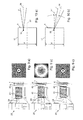
- FIG. 2 a illustrates, in which - represents a representative of a plurality of two-dimensional sections - a first, second and third two-dimensional section 34, 35 and 36, respectively, by a space element 33 of the sample 1.
- a two-dimensional section "wanders" in the direction a through the considered spatial element 33 of the sample 1 in synchronism with the macroscopic movement of the second reference mirror 12, without having to move it itself.
- Each section 34, 35 or 36 lies at a depth T1, T2 or T3 of the sample 1, in which the coherence condition is fulfilled in each case, so that an interference between the light reflected by the third reference mirror 25 and that of the sample 1 can occur ,
- the macroscopic movement of the second reference mirror 12 in combination with the successive two-dimensional detection of the light reflected by the sample 1 thus has the effect of a three-dimensional depth scan.
- Fig. 2 b shows in comparison to a method used in the prior art.
- the sample 1 In order to obtain cuts of different depths 37 through the observed spatial element 33, the sample 1 itself has to be moved in the direction b relative to the interferometer, while the absolute position of the cut 38 in the space remains essentially unchanged.
- the three-dimensional data set obtained in this way allows an exact diagnosis, in particular for biological samples.
- software-assisted diagnostic aids with particularly high efficiency can be used, such as e.g. the so-called "3d rendering", in which a three-dimensional data set is processed by a special software so that a quasi-three-dimensional image is generated on a two-dimensional monitor.
- 3d rendering in which a three-dimensional data set is processed by a special software so that a quasi-three-dimensional image is generated on a two-dimensional monitor.
- cavities or Gewebeabitesen can be represented as a three-dimensional animation - comparable to computer tomography (CT) -.
- the OCT system described above is designed so that during a full stroke, i. the path length L or the double amplitude A, the movement of the second reference mirror 12 is always an interference signal with sufficiently high intensity and high sharpness is obtained.
- the focus tracking described in more detail below ensures that the interference signal and the sharpness of the detected interference pattern are maximal for all depths in the sample 1.
- the focus, ie the focal point, of the sample-side imaging optics of the second interferometer 20 is set in such a way that the position of the focus in the sample 1 and the position of that plane in the sample 1, in which case in case of Reflection of light, the coherence condition is met and interference occurs, at all times during the recording of a tomogram of the space element 33 of the sample 1 are substantially identical. This will be explained below with reference to 3 a) and 3 b) illustrated.
- FIG. 5 shows the case in which the focus F of the sample objective 41 of the sample arm 22-shown here only in simplified form as a lens-lies in a depth of the sample 1 which does not coincide with the position of the coherence gate K.
- the section through the sample 1 detected within the coherence gate K at the depth Ti is not exactly focused on the detector 30 (see FIG Fig. 1 ) so that information losses would be tolerated in the detection of the interference.
- Fig. 3 b On the other hand, the case where the focus F of the sample objective 41 has been set to be within the coherence gate K at the depth Ti is shown.
- This tracking of the focus F of the sample objective 41 corresponding to the respective depth Ti of the coherence gate K is referred to as focus tracking.
- the second interferometer 20 is focused on the respective position of the coherence gate K at different depths Ti of the sample 1, so that images of high definition are obtained from each depth of the sample 1.
- the maximum optical scanning depth Tm indicates to what depth below the surface of the sample 1 the coherence condition for constructive interference is satisfied and corresponding interference patterns are obtained.
- the focus tracking also ensures that in each sampled depth Ti in the sample 1, the illuminated areas on the immovable third reference mirror 25 in the second interferometer 20 on the one hand and in the respective depth of the sample 1 on the other hand are identical.
- the images of the respective illuminated areas on the reference arm 23 and the sample arm 22 in the common image plane 27a of reference and Probenarm 23 and 22 are identical and exactly superimposed.
- Fig. 4 shows a cross section through the arrangement of the individual optical components in the second interferometer 20.
- the sample objective 41 in the sample 22 preferably comprises a plurality of lenses 42 which can be moved individually and / or in groups in the direction R on the sample 1 and away from it.
- a piezoelectric actuator 40 in particular an ultrasonic piezoelectric motor, is provided, which is coupled to the sample objective 41 or the lenses 42 and moves this or these along one or more guides 38, in particular guide rods or guide grooves.
- the movement of the lenses 42 preferably takes place synchronously with the macroscopic movement of the reference mirror 12 in the first interferometer 10 (see FIG Fig. 1 ).
- the focus F of the sample objective 41 follows the coherence gate G, while the latter passes successively different depths T1, T2 and T3 of the sample 1, from which with the aid of the detector 30 two-dimensional sections 34, 35 and 36 (see FIG , Fig. 2 ).
- the synchronization of the macroscopic movement of the reference mirror 12 and the focus tracking on the one hand in combination with a two-dimensional detector 30 on the other hand ensures a particularly simple and fast recording a variety of sharp two-dimensional image sections at different depths of the sample 1 and thus the detection of a full three-dimensional image data set with high image quality ,
- the interference signals detected by the detector 30 are maximal for each depth in the sample 1, resulting in a very high signal-to-noise ratio.
- this ensures that the lateral resolution for all depths in the sample 1 optimal is because the focus F of the image is always in the coherence gate K. It preserves true-to-detail, high-contrast OCT images.
- the speed v2 of the movement of the lenses 42 of the sample objective 41 in the direction R is smaller than the speed v1 of the movement of the reference mirror 12.
- a ratio v1 / v2 of the speeds of the reference mirror 12 and the lenses 42 is chosen to be approximately equal to 2 N is 1 or up to about ⁇ 20%, preferably up to about ⁇ 10%, by this value.
- the coherence gate K and the focus F would diverge during a displacement of the reference mirror 12 and the sample objective 41 by the same path during a depth scan over a macroscopic depth range.
- the ratio v1 / v2 of the speeds of the reference mirror 12 and the lenses 42 ensures that the coherence gate K and the focus F are superimposed on each other during the depth scan in the entire depth range considered.
- the synchronization of the movement of the reference mirror 12 and the lenses 42 is preferably carried out in such a way that reference mirror 12 and lenses 42 at a given time two different, predefined spatial points with each constant, predefined and different speeds v1 and v2 go through.
- the recording of the actual OCT signals begins to the predefined depth in the sample 1.
- OCT- Signals are recorded.
- the synchronization of reference mirror 12 and lens 42 is carried out analogously and is set again after each change of direction.
- the measuring head in which the sample objective 41 is located, is freely movable relative to the first interferometer 10, in which the second reference mirror 12 is located.
- a mechanical coupling of sample objective 41 and reference mirror 12 to synchronize the lens and reference mirror movements would result in insufficient accuracy of synchronization.
- the synchronization of the movements of the reference mirror 12 on the one hand and the lenses 42 of the sample objective 41 on the other hand therefore, preferably takes place by electronic means. It is advantageous to provide in the region of the reference mirror 12 and the lenses 42 of the sample objective 41 each have a position sensor 5 and 39, which detects the current reference mirror or lens position and converts it into corresponding position signals. The two position signals are fed to a control unit, in particular the computer system 16, which accordingly controls the drive of the reference mirror 12 or the lenses 42 accordingly.
- the control of the reference mirror 12 and the lenses 42 is preferably carried out via a feedback of the position signals by means of a so-called. Master-slave system.
- a measured position value in a first positioning unit is the basis for a desired value of the control loop for a second positioning unit.
- the measured position of the first positioning unit of the reference mirror 12 is multiplied by a factor of less than 1 and fed to the second positioning unit of the lenses 42 as a new desired value.
- the relative positional error between the movable reference mirror 12 and the lenses 42 is thereby minimized, even with a relatively large absolute positioning error of the first positioning unit.
- the two components are thereby coupled together in an electronic way as via a mechanical transmission, whereby this can also be referred to as electronic gearing.
- the focus tracking can alternatively or additionally be realized in that an adaptive lens is provided in the sample objective 41, whose imaging properties can be selectively controlled and changed.
- an adaptive lens can be driven electrically such that their radii of curvature change, whereby their focus can be changed and easily adapted to the respective position of the coherence gate.
- the speed and the beginning of the change of the focus F of the adaptive lens must be synchronized with the movement of the reference mirror 12 analogously to the methods described above.
- a material layer 43 (see FIG Fig. 4 ), which preferably consists of sapphire glass.
- the material layer 43 is coated on the inner side 44 with an anti-reflection layer and preferably uncoated on the sample-side outer side 45.
- the OCT system can operate in a diagnostic mode and in a calibration mode.
- the diagnostic mode corresponding to the normal measuring operation
- the sample-side outside 45 of the material layer 43 is coated with an index matching gel and brought into contact with the sample 1 to be examined, from which three-dimensional images are taken.
- the calibration mode the relative position of the focus F of the sample objective 41 is determined to the coherence gate K, wherein the outer side 45 of the material layer 43, which is preferably in air during the calibration, serves as a reference surface.
- the calibration can also be carried out in such a way that the sample objective 41 moves toward the second beam splitter 24 during the calibration.
- the coherence gate and focus position are identical.
- the determined positions P9 'and Xm are set in the diagnostic mode as the initial position of the lens or lenses or of the reflector.
- an additional element made of glass or plastic can be placed on the material layer, a so-called target.
- the method described above is then performed for two or more depths within the additional element. Thereby, not only an offset, that is, an offset of the reference points of movement of the reference mirror 12 and the lenses 42, but also any nonlinearity can be corrected.
- a plurality of reference surfaces are then used, wherein a plurality of position pairs are determined for which focus position and coherence gate are identical. This not only allows a constant relative position error be corrected between the two positioning units, but also any errors in the relative linearity or the relative speed of the two units can be corrected. Such errors can eg result from aging of the position sensors 5 and 39, if, for example, the position sensitivity of one of the two position sensors 5 and 39 changes.
- the dynamic synchronization of focus position and coherence gate in the diagnostic mode of the described OCT system leads to a number of advantages in terms of image quality and reliability. With additional, in particular regular, application of the described calibration mode, this synchronization can be guaranteed over a long period of time.
- the resulting interference pattern is detected with the detector 30, wherein a corresponding interference signal is generated.
- the sampling rate of the detector 30 for sampling the interference signal must be chosen such that the temporal variation of the interference structure can be detected with sufficient accuracy. This generally requires high sampling rates when high speeds are to be achieved for a depth scan.
- the maximum possible scanning speed in the direction of the depth of the sample 1 is dependent on the maximum possible sampling rate of the detector 30.
- the maximum sampling rate is typically in the range of about 1 kHz. This leads to a maximum speed at a mean wavelength of the injected light 14 of, for example, 850 nm for the depth scan of about 0.1 mm / s when recording four points per period of the interference structure.
- Fig. 6 a shows the time course of a typical interference signal, which is sampled at a sampling rate of four sampling times P per period. By way of example, four such points within a period of the interference signal are shown in the figure.
- the intensity of the light 14 coupled into the first interferometer 10 is modulated in time in the present OCT system.
- Typical frequencies of this modulation are in the range between 1 kHz and 25 kHz.
- the intensity of the light emitted by the first interferometer 10 of the third sub-beam 4 can be modulated with the modulation frequency f M in order to achieve the above-described advantageous effect.
- the modulation is preferably carried out during the coupling of the light of the third partial beam 4 in the first optical fiber 17 at the output 8 of the first interferometer 10.
- the intensity modulation can also be done in the second interferometer 10 before the output of the light of the third partial beam 4.
- an optical element is preferably provided which can be arranged, for example, in the first interferometer 10 or in the region of the output 8 of the first interferometer 10 and selectively changed in its transmission or imaging properties.
- the intensity of the light emitted by the first interferometer 10 of the third partial beam 4 are periodically switched from “high” to "low".
- the optical element can also be arranged in the beam path of the first interferometer 10, for example between one of the reference mirrors 11 and 12 and the first beam splitter 13.
- the exact choice of the modulation frequency is made as a function of the central wavelength ⁇ 0 of the injected light 14 of the light source 15, the desired scanning speed of the depth scan and the maximum sampling rate of the detector 30.
- the modulation frequency is preferably selected such that it corresponds to the maximum sampling rate of the detector 30 or an integral multiple thereof.
- the maximum sampling rate is given here by the reciprocal value of the minimum frame time of the detector 30.
- the minimum frame time of the detector 30 is composed of the minimum time necessary to capture a complete image and the minimum dead time of the detector 30 which elapses until the next image can be recorded. The minimum frame time generally increases as the size of the recorded image increases.
- the form of the modulation of the intensity of the light 14 is preferably sinusoidal or rectangular.
- the latter form can simply be achieved by means of a rotating chopper wheel 18 (see Fig. 1 ) will be realized.
- Other possibilities are acousto-optic or electro-optical modulators or liquid crystal modulators.
- a direct modulation of the light source 15 is possible by this is controlled so that it outputs the light 14 with temporally modulated intensity.
- a corresponding effect can alternatively or additionally be achieved in that an optical element, for example, before or after the first beam splitter 13 (see Fig. 1 ) is switched in its transmission or imaging property.
- an optical element for example, before or after the first beam splitter 13 (see Fig. 1 ) is switched in its transmission or imaging property.
- the described modulation of the intensity of the coupled-in light 14 with, preferably slightly, a modulation frequency deviating from the Doppler frequency produces a low-frequency beat between the modulation and the interference signal.
- Fig. 6b shows the time course of a due to the described modulation of the injected light 14 received beat signal, which - like the interference signal in the example of Fig. 6 a) - Is sampled at a sampling rate of four sampling times P per period.
- the sampling of the beat signal significantly fewer sampling times P per unit time are required due to the lower frequency than in the sampling of the interference signal in Fig. 6 a) , so that at a fixed, given by the choice of the detector 30 sampling rate significantly higher speeds for the depth scan can be achieved.
- the integration time of the detector 30 corresponds to the time duration during which the detector 30 detects and integrates the light striking the detector elements in the region of a time P.
- the detector 30 is preferably operated so that the integration time is only slightly shorter than the frame time.
- the frame time is chosen so that it corresponds exactly to the duration of a period of modulation or an integer multiple thereof. This in Fig. 6b) Beating signal shown was obtained by integration over the duration of two periods of modulation.
- the frame time - and thus the integration time - of the detector 30 would be shorter, since the Doppler frequency would increase and thereby temporally narrower sampling times P necessary would.
- a shorter integration time would lead to a reduction in the photons collected per integration and per detector element, which would lead to a reduction of the signal-to-noise ratio due to the so-called Schott noise resulting from the statistical nature of the photons.
- the intensity of the injected light 14 would have to be increased in proportion to the scan speed.
- the scan speed is increased with the aid of the above-described modulation of the intensity of the light 14, then the integration time can remain constant. There is only a 50% light loss due to the modulation of light 14.
- the preferred modulation frequency which is twice the reciprocal of a frame time, there is an increase in speed by a factor of 8. In this case, four times less light intensity is necessary. to achieve this speed increase, as in the case without modulation. The effects of light loss of 50% due to the modulation are overcompensated.
- the required intensity of the light 14 of the light source 15 therefore does not have to be increased with the scanning speed in the described method-in contrast to direct sampling without beating-since in this case the integration time of the detector 30 can remain constant.
- Another advantage of light modulation is the reduction in the amount of data for a full three-dimensional depth scan.
- the amount of data is reduced to 750 MB.
- the directly obtained data must be additionally processed to represent the image result. Again, this is the reduced amount of data very advantageous, as this significantly reduces the processing time and thus the image result is faster.
- the Doppler frequency and / or the modulation frequency are chosen such that a period of the resulting beat signal is an integer multiple of the minimum frame time of the detector 30, i. the maximum sampling rate of the detector 30 is an integer multiple of the frequency of the beat signal.
- the scan speed increases by a factor of 4 compared to the scan speed with unmodulated light 14.
- the scan speed increases by a factor of 8.
- Fig. 6c shows the envelope Eu or Em of the in the FIGS. 6 a)
- each point P 'of the envelope Eu or Em corresponds to a sampling instant P of the associated interference signal or beat signal.
- the above-described principle of modulation of the intensity of the light 14 coupled into the first interferometer 10 or the light of the third partial beam 4 output by the first interferometer can be analogously transmitted to the sensitivity of the detector system, which includes the detector 30 and the detector objective 31 in that the sensitivity of the detector system, in particular of the detector 30, for the light to be detected is modulated at a frequency which is preferably greater or less than the Doppler frequency f D by a certain amount, in particular by up to 40%.
- the light reflected from the sample 1 and incident on the detector 30 is superimposed with the modulated sensitivity of the detector system 30, 31 so that the detector 30 detects the interference pattern incident on the detector 30 instead of a high-frequency interference signal having a plurality of periods Low-frequency beat signal generated, which has significantly fewer periods than the high-frequency interference signal.
- Low-frequency beat signal generated which has significantly fewer periods than the high-frequency interference signal.
- the sensitivity of the detector 30 can be e.g. modulate directly or with a controllable electronic shutter arranged in front of the detector 30.
- properties of an optical element in the detector system such as those shown in FIG. the transmittance of the detector lens 31 for the light reflected from the sample 1 is modulated.
- FIG Fig. 7 shows a highly schematic electrical circuit, explained in more detail.
- Each of the detector elements 80 of a CMOS detector can be simplified in the equivalent circuit diagram shown as a photodiode 81, which is biased by a voltage U1.
- a photodiode 81 which is biased by a voltage U1.
- an ohmic resistor and a capacitor connected in parallel with the photodiode 81 By irradiating the detector element 80 with light, charge carriers are generated in the photodiode 81, which trigger a current flow I1 which is summed up in a capacitor 82 of an electronic integrator 83.
- a switch 84 which is controlled by the modulation frequency f M , the amount of charge and thus the respectively currently detected light intensity with the modulation frequency f M is modulated.
- a sample-and-hold stage 87 the corresponding detector signal is tapped and fed to further processing.
- the further switches 85 and 86 serve to control the resetting of the integration or tapping of the detector signal.
- a low-frequency beat signal (cf. FIG. 2) is also used in this variant instead of a high-frequency interference signal.
- Fig. 6 a) or b) which can be scanned with significantly fewer sampling times P, without losing relevant information. For a given maximum sampling rate of the detector 30, this has the consequence that the maximum speed for a depth scan of the system can be increased by a multiple.
- the scan frequency of the sensitivity of the detector system 30, 31 is also suitably selected by comparison with systems having a constant detector sensitivity. Speed increased by a factor of 4 or even 8.
- the speed of movement of the second reference mirror 12 is in a fixed relationship to the frequency of the modulation of the sensitivity of the detector 30 and is preferably chosen such that an integral number of sampling times, preferably four sampling times, fit into a period of the resulting beat signal (cf. Fig. 6b) ).
- the beat signals sampled in this way must still be processed before visualization, since the interference information is still contained in these signals.
- the essential information to be visualized is the amplitude and depth position of the respective interference, but not the interference structure itself.
- the beat signal must be demodulated, ie the envelope of the beat signal is determined (see Em Fig. 6c) ).
- phase of the beat signal is generally unknown and can also differ for different beat signals from different depths
- a digital demodulation algorithm is used, which is independent of the phase.
- so-called 90 ° phase shift algorithms are used for sampling the interference signal with four sampling times per period. As a result, a fast demodulation of the beat signal is achieved.
- the structure of the measuring head which includes the second interferometer 20, based on the FIGS. 4 . 8th and 9 explained in more detail.
- the second interferometer 20 is a so-called Linnik interferometer.
- Fig. 8 shows an example of a typical structure of such a Linnik interferometer with beam splitter 77, reference mirror 78, detector 79 and sample 70.
- a Linnik interferometer of a miniaturization principle limits set which in particular for the diameter of the optical elements used, such as the lenses 75 and 76 and the lenses 71 and 74, and the geometric structure applies.
- the structure of the sample or reference lens 75 or 76 and their distance q to the beam splitter 77 are substantially equal.
- the distances between the sample and reference objective 41 and 46 to the second beam splitter 24 because of focus tracking generally not the same for all scan depths. This can lead to large relative optical path length differences (OPD) between image center and image edge of the sample and reference image. These can have the consequence that the spatial frequency of the interference structure to be detected becomes greater than the resolution of the two-dimensional detector 30, as a result of which the interference can no longer be detected or can only be detected with insufficient reliability.
- OPD optical path length differences
- the sample and reference lenses 41 and 46 are designed differently ("asymmetrically") and matched to one another, as described below with reference to FIG Fig. 4 is explained in more detail.
- the distance p of the sample objective 41, in particular of the lenses 42, to the second beam splitter 24 is chosen to be very small.
- the distance p is preferably between 1 and 3 mm.
- the sample and reference optics are telecentric on the side of the sample 1 and the third reference mirror 25, respectively. Telecentric optics are characterized in that the object distance can be varied and the image size nevertheless remains constant. This is achieved by an aperture stop.
- the numerical aperture for imaging the sample 1 is relatively large, preferably about 0.3.
- the numerical aperture of the illumination of the sample 1 is smaller than the numerical aperture for the imaging of the sample 1 and preferably has a value of 0.2.
- the advantage is achieved that the light reflected at slanted sample structures light is still collected by the sample objective 41, since the acceptance angle of the sample objective 41 is greater than the divergence angle of the illumination cone.
- the numerical aperture for illumination and imaging were the same size, then less light would be collected in the reflection on inclined sample structures than in the reflection on structures that are perpendicular to the optical axis.
- the smaller numerical aperture for the illumination is realized by the choice of the illumination objective 48 in the illumination arm 21.
- the numerical aperture in the reference arm 23 is equal to or slightly larger than the numerical aperture of the illumination arm 21. This is particularly advantageous in the case of the folded Linnik interferometer used here, since in this way the reference objective 46 is adapted relatively simply to the sample objective 41 and moreover compactly realized can be.
- the optical path through the lenses 49 of the reference lens 46 (including any air gaps between the lenses 49) is shorter than the optical path through the group of lenses 42 of the sample objective 41.
- the coherence gate K lies in an upper layer 34 of the considered spatial element 33 of the sample 1 (cf. Fig. 2 a) ).
- the sample objective 41 in this case has a small distance to the second beam splitter 24 and a relatively large distance to the material layer 43 and the sample 1.
- the coherence gate K lies in a middle layer 35 of the observed spatial element 33 of the sample 1 (cf. Fig. 2 a) ).
- the sample objective 41 is in a position slightly farther from the second steel divider 24 and slightly closer to the material layer 43 than in FIG Fig. 9 a) ,
- the interference structure in this case has a longer period length than in Fig. 9 a) , so that at this time the Nyquist condition is fulfilled.
- the coherence gate K lies in the deepest layer 36 of the considered spatial element 33 of the sample 1 (cf. Fig. 2 a) ).
- the sample objective 41 is in a position further away from the second steel divider 24 and closer to the material layer 43 than in FIG Fig. 9b) ,
- the interference structure in this case has about the same period length as the in Fig. 9 a) represented time, so that in this deep scan position, the Nyquist condition is met.
- the sample objective 41 can thereby be brought close to the second beam splitter 24 at a distance p, as a result of which small diameters of the lenses 42 can be realized with high luminous efficacy.
- the reference lens 46 can be arranged at a significantly greater distance r (r> p) from the second beam splitter 24, thereby enabling a convolution of the second interferometer 20, in which reference and illumination arms 23 and 21 respectively at 90 ° to their Position in an unfolded Linnik interferometer (cf. Fig. 8 ) are tilted and thereby parallel to the sample 22 run.
- the reference lens 46 By the above-described embodiment of the reference lens 46, a part of the optical path necessary for convolution is compensated. Thus, the reference lens 46 is optically shorter than the sample objective 41. This makes the execution of the first interferometer 10 easier because it does not require the two interferometer arms of the first interferometer 10 to differ so much from each other to satisfy the coherence condition for the occurrence of interference.
- the difference of the optical path lengths in the reference or sample arm 23 or 22 is preferably at least twice as large as the maximum scan depth Tm (see 3 a) and b) ).
- the maximum optical scanning depth Tm indicates to what depth below the surface of the sample 1 the coherence condition for the occurrence of interference and corresponding interference patterns are obtained. This ensures a clear and simple assignment of the position of the reference mirror 12 in the first interferometer 10 to a certain depth in the sample 1.
- a spatially short or incoherent light source would normally require a relatively complex lens in the region of the output 8 of the first interferometer 10 in order to efficiently emit the outgoing light in the field couple first light guide 17 and thereby avoid light losses.
- an optionally required increase in the light output in the commonly used spatially short or incoherent light sources is limited.
- one or more singlemode light sources each having a high spatial coherence such as e.g. Superluminescence diodes (SLEDs), short pulse lasers or supercontinuum lasers.
- SLEDs Superluminescence diodes
- the light 14 of the light source 15 is coupled into the first interferometer 10, whereby only the so-called Gauss mode, which corresponds to a single mode (singlemode), is transmitted. Only after passing through the first interferometer 10, the spatial coherence of the injected light 14 is destroyed by the light at the output 8 of the first interferometer 10 in the first light guide 17, which has a very long multimode fiber is coupled.
- a multimode fiber is a fiber whose numerical aperture and core diameter allow it to be at a particular wavelength of light can not only form a fiber mode, but many different fiber modes can be excited.
- ⁇ indicates the wavelength of the light coupled into the fiber
- d the core diameter of the fiber
- NA the numerical aperture of the fiber.
- the wavelength ⁇ of the light coupled into the fiber is preferably identical to the mean wavelength ⁇ 0 of the light 14 coupled into the first interferometer 10. If the V number is greater than approximately 2.4, this is a multimode fiber.
- the preferably used in the first optical fiber 17 multimode fiber has typical lengths in the order of about 100 m and is preferably wound for the most part on a winding 19, as in Fig. 1 indicated.
- the core diameter of the multimode fiber is preferably between about 200 ⁇ m and about 400 ⁇ m.
- the very long, thin and preferably wound multimode fiber can optionally be combined in the first light guide 17 with a relatively short, thick fiber (not shown) whose diameter is in the range of about one millimeter and whose length is in the range of meters.
- the destruction of the spatial coherence of the light of the singlemode light source 15 prevents the light reflected from two different locations in the sample 1 from interfering, which is also referred to as coherent cross-talk.
- the pre-modulation information generated in the first interferometer 10, i. however, the spectral modulation of the injected light 14 caused by the movement of the second reference mirror 12 is not changed during the transmission of the light by the very long multimode fiber of the first light guide 17. This is ensured by the fact that both arms of the first interferometer 10 in the multimode fiber generate identical modes with identical mode distribution and identical phases.
- Each mode in turn then transmits the pre-modulation information, with the individual modes not interfacing with each other.
- the entry of the light into the multimode fiber of the first light guide 17 in this case determines the number and distribution of the excited modes in the multimode fiber.
- FIGS. 10 a) and 10 b) In addition, the core diameter d of the multimode fiber used in the first optical fiber 17 is shown.
- high-intensity coherent light sources e.g. SLEDs, short pulse lasers or supercontinuum lasers
- SLEDs short pulse lasers
- supercontinuum lasers can be used as a light source 15
- the signal-to-noise ratio of the acquired image information is thereby significantly improved.
- the first interferometer 10 can also be designed completely as a fiber interferometer.
- the depth scan could then be e.g. instead of the movement of the second reference mirror 12 by stretching a fiber in one of the two arms of the first interferometer 10 by means of a so-called fiber stretcher.
- a depth scan is performed by a macroscopic movement of the reference mirror 12 in the first interferometer 10, while the light reflected from the sample 1 is passed through the second interferometer 20 and the second optical fiber 29 to the two-dimensional detector 30 and detected by this.
- Fiber bundles As the second light guide 29, a fiber bundle composed of a plurality of individual fibers is used. Fiber bundles generally have a high numerical aperture which is technically conditioned and in the range of 0.4 or above. Furthermore, the fill factor of the facet, i. of the inlet or outlet cross-section, the usual fiber bundle relatively low. Both would result in the transmission of the reflected light from the sample 1 from the second interferometer 20 to the detector 30 to unwanted light losses.
- the fiber bundle described in more detail below is used.
- Fig. 11 shows a section 50 of the facet of the fiber bundle used, which - as can be seen from the enlarged portion shown 51 - composed of a plurality of individual fibers 52 having a center-to-center distance d2 (so-called fiber pitch).
- Fig. 12 shows a section of the detector 30 used, which comprises a plurality of arranged in a surface detector elements 80 having a center-to-center distance d1 (so-called pixel pitch).
- pixel pitch a center-to-center distance
- the fiber pitch d2 of the individual fibers 52 of the fiber bundle is smaller than the pixel pitch d1 of the detector elements 80 of the detector 30.
- the fiber bundle consists of at least 100,000, preferably about 300,000, individual fibers 52.
- the number of detector elements 80 of the detector 30 is preferably about 328,000 and is therefore of the same order of magnitude as the number of individual fibers 52nd
- the shape of the cross section of the fiber bundle of the second light guide 29 in the region of the entrance and exit surfaces 7 and 6 is preferably adapted to the geometry of the detector 30, wherein in particular the shape of the entrance surface 7 on the side of the second interferometer 20 is substantially the same the shape of the exit surface 6 on the side of the detector lens 31 and detector 30 is (see also Fig. 1 ).
- the respective shape of the inlet and outlet surfaces 7 and 6, in particular their aspect ratio, is in this case substantially identical to the, preferably rectangular, shape of the detector 30.
- Fig. 14 a By way of example, two individual fibers 52 of the fiber bundle are shown.
- the individual fibers 52 have a fiber core 65 and a fiber cladding 66.
- the ratio d3 / d4 of the thicknesses d3 and d4 of the respective fiber core 65 to the fiber cladding 66 (the so-called core / cladding ratio) is chosen such that the highest possible fill factor is achieved with the lowest possible light losses due to laterally emerging from the fiber 52 light (so-called evanescent waves).
- the fill factor is given here by the ratio of the total cross-sectional area of the individual fiber 52 to the surface of the fiber core 65.
- the fiber bundle used preferably has a fiber pitch d2 of 11 ⁇ m, a shell thickness d4 of the individual fibers 52 of 1.7 ⁇ m and a core diameter d3 of 6.8 ⁇ m.
- the diameter of the individual fiber 52 which results from the sum of the core diameter d3 and the double sheath thickness d4, in this case is 10.2 microns and is thus slightly lower than the fiber pitch d2, as in the manufacturing process of the fiber bundle still a second coat (not shown) about each individual fiber 52 is generated.
- Fig. 14b is a variant of in Fig. 14 a) shown embodiment of the individual fibers 52 shown.
- the individual fiber cores 65 of the individual fibers 52 are embedded in a matrix 66 of glass or plastic, which respectively forms the fiber cladding of each individual fiber core 65.
- each two adjacent individual fibers 52 have a part of their fiber cladding in common.
- the distance d4 of adjacent fiber cores 64 which corresponds to the cladding thickness, can hereby be reduced compared with the individual fibers described above with their own fiber cladding, wherein the occurrence of evanescent waves is furthermore suppressed efficiently.
- the area ratio of the fiber core surface to the entire fiber surface is thereby particularly large.
- the quotient of the core diameter d3 and the cladding thickness d4 lies in the range between approximately 5 and 8.
- the second interferometer 20 is constructed in such a way that a lateral interference pattern results for all scan depths whose spatial frequency is lower than the spatial frequency of the individual fibers 52 of the fiber bundle, in which case the Nyquist condition must be fulfilled.
- a lateral interference pattern results for all scan depths whose spatial frequency is lower than the spatial frequency of the individual fibers 52 of the fiber bundle, in which case the Nyquist condition must be fulfilled.
- Fig. 15 illustrated.
- the length of a period between two successive interference minima 63 (dark rings) of the interference pattern 60 is several times greater than the center-to-center spacing (fiber pitch) of the individual fibers 52 of the fiber bundle whose entrance surface 6 (see also Fig. 1 ) is shown here in sections and in appropriate magnification.
- the spatial frequency of the interference pattern 60 is significantly smaller than the spatial frequency of the individual fibers 52 of the fiber bundle.
- the pixel pitch d1 of InGaAs CMOS detectors which are sensitive to light with wavelengths in the range of about 1300 nm, can not be much smaller than 20 ⁇ m for technical reasons.
- the fiber bundle preferably used in the present OCT system has a fiber pitch d2 of 10 ⁇ m and therefore has a considerably smaller cross-section at the same resolution than the detector. This allows a much more compact construction of the measuring head compared to systems in which the detector is installed in the measuring head.
- a fiber pitch d2 (eg 11 ⁇ m), which is smaller than the smallest possible pixel pitch d1 (usually greater than or equal to 20 ⁇ m) of the detector 30, is preferably selected in the second optical waveguide 29, an enlargement of that obtained from the specimen 1 can be obtained Image can be reduced in the measuring head with the same lateral resolution compared to systems of the prior art, which allows a simpler and smaller optics in the second interferometer 20.
- an adaptation of the numerical apertures of individual components of the present OCT system is provided, in particular the apertures of the sample objective 41 and the lenses 47 in FIG Output arm 27 and the apertures of the reference lens 46 and the fiber bundle of the second light guide 29, the detector lens 31 and the detector 30. This will be described below with reference to FIGS. 1 . 4 and 16 explained in more detail.
- Fig. 16 shows a portion of the composite of a plurality of individual fibers 52 second optical fiber 29 in the region of the entrance surface 7.
- a emerging from the second interferometer 20, convergent light beam 58 has an aperture angle ⁇ and strikes at an angle ⁇ against the normal of the entrance surface 7 on the Light guide 29.
- the individual fibers 52 of the second light guide 27 have an aperture angle ⁇ , within which they can detect incident light.
- the aperture angle ⁇ is given by the numerical aperture of the individual fibers 52.
- the sum of the aperture angle ⁇ of the light beam 58 and the angle of incidence ⁇ is smaller than the aperture angle ⁇ of the individual fibers 52 of the fiber bundle 29: ⁇ + ⁇ ⁇ . This ensures that the entire light of the light bundle 58, which strikes a single fiber 52, enters it and is transported to the exit surface 6 of the second light guide 29.
- the required aperture angle ⁇ and angle of incidence ⁇ of the light beam 58 are realized by a corresponding configuration of the sample and / or reference and / or output objective 41, 46 and 47, respectively. This is achieved in particular by the fact that the two lens combinations of sample and output objective 41/47 or reference and output objective 46/47 display magnifying, ie the aperture angle ⁇ of the light bundle 58 in the region of the entrance surface 7 of the fiber bundle ("image side"). ) is smaller than the aperture angle (not shown) on the side of the sample 1 ("object side"). As a result, a large aperture angle can be easily realized on the side of the sample 1, whereby a high light-collecting efficiency is achieved. Together with the lossless coupling of light into the fiber bundle of the second optical waveguide 29, this ensures an overall very high luminous efficacy in the detection of the light reflected by the specimen 1 and thus achieves a high image quality.
- an adjustment of the fiber bundle-side numerical aperture of the detector objective 31 to the numerical aperture of the fiber bundle of the second optical waveguide 29 is provided to increase the light output.
- the aperture angle of the detector lens 31 is greater than the aperture angle ⁇ of the individual fibers 52 of the fiber bundle.
- the detector lens 31 is telecentric on the fiber bundle side.
- the radiation characteristic of the fiber bundle can be taken into account in a simple manner.
- the field angle on the output surface 6 is zero for each position on the output surface 6.
- the light output detected by the detector 30 decreases. To ensure the highest possible light output is therefore intended to keep the angle of incidence of the light rays on the detector 30 as low as possible. This is preferably achieved by a magnification imaging of the fiber bundle of the second light guide 29 onto the detector 30 and a telecentric design of the detector objective 31 on the side of the detector 30.
- a further advantage of using the described fiber bundle for image transmission is that the total magnification M of the system can be divided into two steps, namely a first magnification M1 in the measuring head, ie in the second interferometer 20, and a second magnification M2 in the detector objective 31 As a result, the first magnification M1 of the objectives 41, 47 and 47 in the measuring head can be smaller than the total magnification M necessary for the nominal resolution of the OCT system.
- the use of the fiber bundle described above thus has the advantage that the total magnification M does not have to be accomplished solely by the objectives of the second interferometer 20, so that the sample and / or reference and / or output objective 41, 46 or 47 of the measuring head simpler and more space-saving can be constructed or can, whereby the measuring head can be made much more compact overall.
- the average diameter D1 of the sample objective 41 or of the lenses 47 of the output objective of the second interferometer 20 can be selected to be smaller than the diameter D2 of the second light guide 29 in the area of the entrance surface 7: D1 ⁇ D2.
- the OCT system described above can be operated in three different operating modes.
- the modes of operation are two real-time modes in which OCT images of a sample are generated at a high rate of about 5 to 10 frames per second, and a static mode of operation.
- the real-time mode 1 two-dimensional depth sections of the sample 1 are generated in real time (so-called slices).
- a CMOS camera is used as the detector 30, which permits the setting of a so-called window of interest (WOI), in which only a partial area of the detector 30 is sensitive to light and converts it into corresponding detector signals.
- WI window of interest
- the reduction of the sensitive camera area is associated with a significant increase in the camera speed; With this setting, more camera images can be generated per second than in full-screen mode.
- a WOI is preferably selected which corresponds in one direction to the total camera length or width (eg 640 pixels) and in the other direction has the minimum possible number of pixels (given by the type of the respective camera) Pixel). This increases the speed of the camera so that OCT images can be captured in real time.
- Fig. 17 shows a detector surface F1, which is composed of a first number N1 of detector elements 80 and has a length c1 and a width b1.
- a detector surface F1 which is composed of a first number N1 of detector elements 80 and has a length c1 and a width b1.
- the second number N2 of the detector elements 80 of the partial area F2 is smaller than the first number N1 of the detector elements 80 of the entire detector area F1.
- the lengths c1 and c2 of the detector surface F1 or partial surface F2 are the same size, while the widths b1 and b2 of the detector surface F1 or partial surface F2 are different.
- the partial area F2 is only four pixels wide, whereas the detector area F1 is 512 pixels wide.
- the sensitive surface of the detector surface F1 is therefore reduced by a factor of 128, which considerably shortens the time required for the detection of interference patterns and their conversion into corresponding detector signals.
- the real-time mode 2 shown - two-dimensional tomograms 68 generated from a certain depth T of the considered space element 33 of the sample 1, wherein the depth T is arbitrary.
- the entire detector surface F1 of the detector 30 is used for detecting the light reflected from the sample 1 and its conversion into corresponding detector signals, but only a maximum of five camera images are used to calculate a tomogram 68.
- the first reference mirror 11 is periodically moved in the first interferometer 10 with an amplitude of about 1 .mu.m, while up to five camera images are recorded, which are then offset to form an OCT image. In this way, tomograms 68 can be generated at a high repetition rate.
- the depth T from which the tomogram 68 is obtained, can be freely selected.
- the static mode a complete three-dimensional data record is recorded by means of the macroscopic movement of the second reference mirror 12 in combination with the focus tracking. Details are given in particular in sections 1 and 2.
- the OCT system can fulfill a number of different requirements.
- the functionalities in the examination of samples for example, finding relevant points in the sample, thereby significantly expanded.
- the above-described system or method for OCT has individual features or combinations of features that make the system or method, in particular, simpler and more compact in terms of handling and image acquisition, faster and more reliable without all the above in the preamble and / or or characterizing part of the independent claims listed features are required. These features or feature combinations are also considered as invention.
- the irradiation of the sample with the light emitted by the interferometer is either indirect, i. via another interferometer, which lies between the interferometer and the sample, or directly, i. without a further interferometer located between the interferometer and the sample.
- the detection of the light reflected from the sample by the detector is either indirect, i. via another interferometer which lies between the sample and the detector, or directly, i. without a further interferometer located between the detector and the sample.
Priority Applications (4)
| Application Number | Priority Date | Filing Date | Title |
|---|---|---|---|
| EP07102821.1A EP1962079B1 (fr) | 2007-02-21 | 2007-02-21 | Système et procédé destinés à la tomographie de cohérence optique |
| PCT/EP2008/052075 WO2008101962A1 (fr) | 2007-02-21 | 2008-02-20 | Système et procédé de tomographie par cohérence optique |
| US12/527,300 US8330962B2 (en) | 2007-02-21 | 2008-02-20 | System and method for optical coherence tomography with modulated detector sensitivity |
| CN200880005843A CN101617216A (zh) | 2007-02-21 | 2008-02-20 | 用于进行光学相干断层扫描的系统和方法 |
Applications Claiming Priority (1)
| Application Number | Priority Date | Filing Date | Title |
|---|---|---|---|
| EP07102821.1A EP1962079B1 (fr) | 2007-02-21 | 2007-02-21 | Système et procédé destinés à la tomographie de cohérence optique |
Publications (2)
| Publication Number | Publication Date |
|---|---|
| EP1962079A1 true EP1962079A1 (fr) | 2008-08-27 |
| EP1962079B1 EP1962079B1 (fr) | 2016-06-01 |
Family
ID=38261592
Family Applications (1)
| Application Number | Title | Priority Date | Filing Date |
|---|---|---|---|
| EP07102821.1A Not-in-force EP1962079B1 (fr) | 2007-02-21 | 2007-02-21 | Système et procédé destinés à la tomographie de cohérence optique |
Country Status (4)
| Country | Link |
|---|---|
| US (1) | US8330962B2 (fr) |
| EP (1) | EP1962079B1 (fr) |
| CN (1) | CN101617216A (fr) |
| WO (1) | WO2008101962A1 (fr) |
Cited By (9)
| Publication number | Priority date | Publication date | Assignee | Title |
|---|---|---|---|---|
| US8526006B2 (en) | 2007-02-21 | 2013-09-03 | Agfa Healthcare Nv | System and method for optical coherence tomography and method for calibrating said type of system |
| US8559016B2 (en) | 2008-12-16 | 2013-10-15 | Agfa Healthcare Nv | Method and system for optical coherence tomography |
| US8593639B2 (en) | 2007-02-21 | 2013-11-26 | Agfa Healthcare Nv | System and method for optical coherence tomography with light or detector modulation |
| US8665449B2 (en) | 2007-02-21 | 2014-03-04 | Agfa Healthcare Nv | System and method for optical coherence tomography |
| US8810797B2 (en) | 2007-02-21 | 2014-08-19 | Agfa Healthcare Nv | System and method for optical coherence tomography |
| US8928890B2 (en) | 2007-02-21 | 2015-01-06 | Agfa Healthcare N.V. | System for optical coherence tomography with different optical properties of specimen and reference objectives |
| WO2016173969A1 (fr) | 2015-04-30 | 2016-11-03 | Agfa Healthcare | Procédé amélioré permettant de générer une image de la morphologie et des éléments cellulaires d'un échantillon ou d'un tissu in vivo au moyen d'une tomographie en cohérence optique à haute résolution |
| WO2017005838A1 (fr) | 2015-07-09 | 2017-01-12 | Agfa Healthcare | Examen non invasif de tissu biologique sur la base d'imagerie par tomographie en cohérence optique haute définition en champ plein |
| EP3150108A4 (fr) * | 2014-05-27 | 2018-01-24 | Koh Young Technology Inc. | Dispositif oct amovible |
Families Citing this family (8)
| Publication number | Priority date | Publication date | Assignee | Title |
|---|---|---|---|---|
| DE502007004384D1 (de) * | 2007-02-21 | 2010-08-26 | Agfa Healthcare Nv | System und Verfahren zur optischen Kohärenztomographie |
| JP5605998B2 (ja) * | 2009-03-06 | 2014-10-15 | キヤノン株式会社 | 光干渉断層撮像方法および装置 |
| US8345257B2 (en) * | 2009-04-20 | 2013-01-01 | D4D Technologies, Llc | Swept source optical coherence tomography (OCT) method and system |
| DE102010033249A1 (de) * | 2010-08-03 | 2012-02-09 | Carl Zeiss Microlmaging Gmbh | Autofokussystem |
| WO2012035148A1 (fr) * | 2010-09-17 | 2012-03-22 | Lltech Management | Système de tomographie par cohérence optique plein champ permettant d'imager un objet |
| EP2498048A1 (fr) | 2011-03-10 | 2012-09-12 | Agfa HealthCare N.V. | Système et procédé destinés à la tomographie de cohérence optique |
| CN104661586A (zh) * | 2012-09-26 | 2015-05-27 | 爱克发医疗保健公司 | 用于光学相干断层成像的方法和系统 |
| EP3003177B1 (fr) | 2013-05-31 | 2021-03-10 | Covidien LP | Dispositif chirurgical avec un ensemble effecteur terminal de suivi d'un tissu pendant une intervention chirurgicale |
Citations (3)
| Publication number | Priority date | Publication date | Assignee | Title |
|---|---|---|---|---|
| US5321501A (en) | 1991-04-29 | 1994-06-14 | Massachusetts Institute Of Technology | Method and apparatus for optical imaging with means for controlling the longitudinal range of the sample |
| US6608717B1 (en) * | 1999-01-29 | 2003-08-19 | Colorado State University Research Foundation | Optical coherence microscope and methods of use for rapid in vivo three-dimensional visualization of biological function |
| US20050219545A1 (en) | 2004-03-30 | 2005-10-06 | Kabushiki Kaisha Topcon | Optical image measuring apparatus |
Family Cites Families (22)
| Publication number | Priority date | Publication date | Assignee | Title |
|---|---|---|---|---|
| US6485413B1 (en) * | 1991-04-29 | 2002-11-26 | The General Hospital Corporation | Methods and apparatus for forward-directed optical scanning instruments |
| JP3234353B2 (ja) * | 1993-06-15 | 2001-12-04 | 富士写真フイルム株式会社 | 断層情報読取装置 |
| DE69510989T2 (de) | 1994-04-28 | 2000-01-20 | Sumitomo Chemical Co | Verfahren zur Herstellung von Alpha-Aluminiumoxidpulver |
| WO1995033970A1 (fr) | 1994-06-02 | 1995-12-14 | Massachusetts Institute Of Technology | Came rotative pour systemes optiques |
| ATA107495A (de) * | 1995-06-23 | 1996-06-15 | Fercher Adolf Friedrich Dr | Kohärenz-biometrie und -tomographie mit dynamischem kohärentem fokus |
| US6053613A (en) | 1998-05-15 | 2000-04-25 | Carl Zeiss, Inc. | Optical coherence tomography with new interferometer |
| WO2001069302A2 (fr) * | 2000-03-13 | 2001-09-20 | Genospectra, Inc. | Scanneur a fibre optique |
| DE10053154B4 (de) * | 2000-10-26 | 2011-02-17 | Carl Zeiss Meditec Ag | Optische Kohärenz-Interferometrie und Kohärenz-Tomographie mit räumlich teilhärenten Lichtquellen |
| US7355716B2 (en) * | 2002-01-24 | 2008-04-08 | The General Hospital Corporation | Apparatus and method for ranging and noise reduction of low coherence interferometry LCI and optical coherence tomography OCT signals by parallel detection of spectral bands |
| US6810175B1 (en) | 2002-04-22 | 2004-10-26 | Terabeam Corporation | Off-axis mode scrambler |
| US20070273713A1 (en) * | 2004-04-01 | 2007-11-29 | Koninklijke Philips Electronics, N.V. | Driving a matrix display |
| WO2006102997A1 (fr) | 2005-03-30 | 2006-10-05 | Carl Zeiss Smt Ag | Procede de fabrication d'un element optique |
| US7291856B2 (en) | 2005-04-28 | 2007-11-06 | Honeywell International Inc. | Sensor and methods for measuring select components in moving sheet products |
| JP5558005B2 (ja) * | 2006-01-23 | 2014-07-23 | ザイゴ コーポレーション | 物体をモニタする干渉計システム |
| EP1962049B1 (fr) * | 2007-02-21 | 2015-12-23 | Agfa HealthCare N.V. | Système et procédé pour la tomographie par cohérence optique |
| EP1962051A1 (fr) * | 2007-02-21 | 2008-08-27 | Agfa HealthCare N.V. | Système et procédé destinés à la tomographie de cohérence optique |
| EP2339329A3 (fr) * | 2007-02-21 | 2012-04-04 | Agfa HealthCare N.V. | Système et procédé destinés à la tomographie par cohérence optique |
| ATE511635T1 (de) * | 2007-02-21 | 2011-06-15 | Agfa Healthcare Nv | System zur optischen kohärenztomographie |
| EP2267403A3 (fr) * | 2007-02-21 | 2011-04-20 | Agfa HealthCare N.V. | Système et procédé destinés à la tomographie de cohérence optique |
| DE502007004384D1 (de) * | 2007-02-21 | 2010-08-26 | Agfa Healthcare Nv | System und Verfahren zur optischen Kohärenztomographie |
| EP1962081B1 (fr) * | 2007-02-21 | 2016-09-14 | Agfa HealthCare N.V. | Système destiné à la tomographie de cohérence optique |
| EP2199734B1 (fr) * | 2008-12-16 | 2016-03-09 | Agfa HealthCare NV | Méthode et système pour Tomographie Optique Cohérente |
-
2007
- 2007-02-21 EP EP07102821.1A patent/EP1962079B1/fr not_active Not-in-force
-
2008
- 2008-02-20 CN CN200880005843A patent/CN101617216A/zh active Pending
- 2008-02-20 WO PCT/EP2008/052075 patent/WO2008101962A1/fr active Application Filing
- 2008-02-20 US US12/527,300 patent/US8330962B2/en not_active Expired - Fee Related
Patent Citations (3)
| Publication number | Priority date | Publication date | Assignee | Title |
|---|---|---|---|---|
| US5321501A (en) | 1991-04-29 | 1994-06-14 | Massachusetts Institute Of Technology | Method and apparatus for optical imaging with means for controlling the longitudinal range of the sample |
| US6608717B1 (en) * | 1999-01-29 | 2003-08-19 | Colorado State University Research Foundation | Optical coherence microscope and methods of use for rapid in vivo three-dimensional visualization of biological function |
| US20050219545A1 (en) | 2004-03-30 | 2005-10-06 | Kabushiki Kaisha Topcon | Optical image measuring apparatus |
Non-Patent Citations (3)
| Title |
|---|
| GRIEVE K ET AL: "In vivo anterior segment imaging in the rat eye with high speed white light full-field optical coherence tomography", OPTICS EXPRESS OPT. SOC. AMERICA USA, vol. 13, no. 16, 8 August 2005 (2005-08-08), pages 6286 - 6295, XP002444205, ISSN: 1094-4087, [retrieved on 20070725] * |
| W. Y. OH ET AL., OPTICS EXPRESS, vol. 14, no. 19, 2006, pages 8675 - 8684 |
| WATANABE Y ET AL: "Three-dimensional imaging by ultrahigh-speed axial-lateral parallel time domain optical coherence tomography", OPTICS EXPRESS OPT. SOC. AMERICA USA, vol. 14, no. 12, June 2006 (2006-06-01), pages 6286 - 6295, XP002443953, ISSN: 1094-4087 * |
Cited By (11)
| Publication number | Priority date | Publication date | Assignee | Title |
|---|---|---|---|---|
| US8526006B2 (en) | 2007-02-21 | 2013-09-03 | Agfa Healthcare Nv | System and method for optical coherence tomography and method for calibrating said type of system |
| US8593639B2 (en) | 2007-02-21 | 2013-11-26 | Agfa Healthcare Nv | System and method for optical coherence tomography with light or detector modulation |
| US8665449B2 (en) | 2007-02-21 | 2014-03-04 | Agfa Healthcare Nv | System and method for optical coherence tomography |
| US8810797B2 (en) | 2007-02-21 | 2014-08-19 | Agfa Healthcare Nv | System and method for optical coherence tomography |
| US8908190B2 (en) | 2007-02-21 | 2014-12-09 | Agfa Healthcare Nv | System and method for focus tracking optical coherence tomography |
| US8928890B2 (en) | 2007-02-21 | 2015-01-06 | Agfa Healthcare N.V. | System for optical coherence tomography with different optical properties of specimen and reference objectives |
| US8559016B2 (en) | 2008-12-16 | 2013-10-15 | Agfa Healthcare Nv | Method and system for optical coherence tomography |
| EP3150108A4 (fr) * | 2014-05-27 | 2018-01-24 | Koh Young Technology Inc. | Dispositif oct amovible |
| US10986996B2 (en) | 2014-05-27 | 2021-04-27 | Koh Young Technology Inc. | Removable Optical Coherence Tomography (OCT) device |
| WO2016173969A1 (fr) | 2015-04-30 | 2016-11-03 | Agfa Healthcare | Procédé amélioré permettant de générer une image de la morphologie et des éléments cellulaires d'un échantillon ou d'un tissu in vivo au moyen d'une tomographie en cohérence optique à haute résolution |
| WO2017005838A1 (fr) | 2015-07-09 | 2017-01-12 | Agfa Healthcare | Examen non invasif de tissu biologique sur la base d'imagerie par tomographie en cohérence optique haute définition en champ plein |
Also Published As
| Publication number | Publication date |
|---|---|
| WO2008101962A1 (fr) | 2008-08-28 |
| EP1962079B1 (fr) | 2016-06-01 |
| US8330962B2 (en) | 2012-12-11 |
| CN101617216A (zh) | 2009-12-30 |
| US20100097616A1 (en) | 2010-04-22 |
Similar Documents
| Publication | Publication Date | Title |
|---|---|---|
| EP1962050B1 (fr) | Système et procédé pour la tomographie par cohérence optique ainsi qu'un procédé de calibrage d'un tel système | |
| EP1962080B1 (fr) | Système destiné à la tomographie de cohérence optique | |
| EP1962079B1 (fr) | Système et procédé destinés à la tomographie de cohérence optique | |
| EP1962081B1 (fr) | Système destiné à la tomographie de cohérence optique | |
| EP1962049B1 (fr) | Système et procédé pour la tomographie par cohérence optique | |
| EP1962052B1 (fr) | Système et procédé destinés à la tomographie de cohérence optique | |
| EP1962082A1 (fr) | Système et procédé destinés à la tomographie par cohérence optique | |
| EP1962051A1 (fr) | Système et procédé destinés à la tomographie de cohérence optique | |
| EP0167877B1 (fr) | Appareil destiné à visualiser des sections de l'oeil humain | |
| EP0168643B1 (fr) | Dispositif pour l'inspection de pastilles de semi-conducteurs | |
| EP2702935A1 (fr) | Système et procédé destinés à la tomographie de cohérence optique ainsi que l'élément de positionnement | |
| EP1918754B1 (fr) | Microscope d'opération doté d'un système OCT | |
| EP2508841B1 (fr) | Procédé et système destinés à la tomographie de cohérence optique | |
| EP2199734A1 (fr) | Méthode et système pour tomographie optique cohérente | |
| EP2508843B1 (fr) | Procédé et système destinés à la tomographie de cohérence optique | |
| WO2012119695A1 (fr) | Système et procédé de tomographie à cohérence optique | |
| EP2508842B1 (fr) | Procédé et système destinés à la tomographie de cohérence optique | |
| DE102010028913A1 (de) | Mikroskop und Verfahren zur Hautuntersuchung |
Legal Events
| Date | Code | Title | Description |
|---|---|---|---|
| PUAI | Public reference made under article 153(3) epc to a published international application that has entered the european phase |
Free format text: ORIGINAL CODE: 0009012 |
|
| AK | Designated contracting states |
Kind code of ref document: A1 Designated state(s): AT BE BG CH CY CZ DE DK EE ES FI FR GB GR HU IE IS IT LI LT LU LV MC NL PL PT RO SE SI SK TR |
|
| AX | Request for extension of the european patent |
Extension state: AL BA HR MK RS |
|
| 17P | Request for examination filed |
Effective date: 20090227 |
|
| 17Q | First examination report despatched |
Effective date: 20090327 |
|
| AKX | Designation fees paid |
Designated state(s): AT BE BG CH CY CZ DE DK EE ES FI FR GB GR HU IE IS IT LI LT LU LV MC NL PL PT RO SE SI SK TR |
|
| GRAP | Despatch of communication of intention to grant a patent |
Free format text: ORIGINAL CODE: EPIDOSNIGR1 |
|
| INTG | Intention to grant announced |
Effective date: 20151202 |
|
| GRAP | Despatch of communication of intention to grant a patent |
Free format text: ORIGINAL CODE: EPIDOSNIGR1 |
|
| GRAS | Grant fee paid |
Free format text: ORIGINAL CODE: EPIDOSNIGR3 |
|
| GRAA | (expected) grant |
Free format text: ORIGINAL CODE: 0009210 |
|
| INTG | Intention to grant announced |
Effective date: 20160411 |
|
| AK | Designated contracting states |
Kind code of ref document: B1 Designated state(s): AT BE BG CH CY CZ DE DK EE ES FI FR GB GR HU IE IS IT LI LT LU LV MC NL PL PT RO SE SI SK TR |
|
| REG | Reference to a national code |
Ref country code: GB Ref legal event code: FG4D Free format text: NOT ENGLISH |
|
| REG | Reference to a national code |
Ref country code: CH Ref legal event code: EP Ref country code: AT Ref legal event code: REF Ref document number: 804177 Country of ref document: AT Kind code of ref document: T Effective date: 20160615 |
|
| REG | Reference to a national code |
Ref country code: IE Ref legal event code: FG4D Free format text: LANGUAGE OF EP DOCUMENT: GERMAN |
|
| REG | Reference to a national code |
Ref country code: DE Ref legal event code: R096 Ref document number: 502007014852 Country of ref document: DE |
|
| REG | Reference to a national code |
Ref country code: LT Ref legal event code: MG4D |
|
| REG | Reference to a national code |
Ref country code: NL Ref legal event code: MP Effective date: 20160601 |
|
| PG25 | Lapsed in a contracting state [announced via postgrant information from national office to epo] |
Ref country code: FI Free format text: LAPSE BECAUSE OF FAILURE TO SUBMIT A TRANSLATION OF THE DESCRIPTION OR TO PAY THE FEE WITHIN THE PRESCRIBED TIME-LIMIT Effective date: 20160601 Ref country code: LT Free format text: LAPSE BECAUSE OF FAILURE TO SUBMIT A TRANSLATION OF THE DESCRIPTION OR TO PAY THE FEE WITHIN THE PRESCRIBED TIME-LIMIT Effective date: 20160601 |
|
| PG25 | Lapsed in a contracting state [announced via postgrant information from national office to epo] |
Ref country code: NL Free format text: LAPSE BECAUSE OF FAILURE TO SUBMIT A TRANSLATION OF THE DESCRIPTION OR TO PAY THE FEE WITHIN THE PRESCRIBED TIME-LIMIT Effective date: 20160601 Ref country code: GR Free format text: LAPSE BECAUSE OF FAILURE TO SUBMIT A TRANSLATION OF THE DESCRIPTION OR TO PAY THE FEE WITHIN THE PRESCRIBED TIME-LIMIT Effective date: 20160902 Ref country code: SE Free format text: LAPSE BECAUSE OF FAILURE TO SUBMIT A TRANSLATION OF THE DESCRIPTION OR TO PAY THE FEE WITHIN THE PRESCRIBED TIME-LIMIT Effective date: 20160601 Ref country code: LV Free format text: LAPSE BECAUSE OF FAILURE TO SUBMIT A TRANSLATION OF THE DESCRIPTION OR TO PAY THE FEE WITHIN THE PRESCRIBED TIME-LIMIT Effective date: 20160601 Ref country code: ES Free format text: LAPSE BECAUSE OF FAILURE TO SUBMIT A TRANSLATION OF THE DESCRIPTION OR TO PAY THE FEE WITHIN THE PRESCRIBED TIME-LIMIT Effective date: 20160601 |
|
| PG25 | Lapsed in a contracting state [announced via postgrant information from national office to epo] |
Ref country code: SK Free format text: LAPSE BECAUSE OF FAILURE TO SUBMIT A TRANSLATION OF THE DESCRIPTION OR TO PAY THE FEE WITHIN THE PRESCRIBED TIME-LIMIT Effective date: 20160601 Ref country code: IT Free format text: LAPSE BECAUSE OF FAILURE TO SUBMIT A TRANSLATION OF THE DESCRIPTION OR TO PAY THE FEE WITHIN THE PRESCRIBED TIME-LIMIT Effective date: 20160601 Ref country code: EE Free format text: LAPSE BECAUSE OF FAILURE TO SUBMIT A TRANSLATION OF THE DESCRIPTION OR TO PAY THE FEE WITHIN THE PRESCRIBED TIME-LIMIT Effective date: 20160601 Ref country code: IS Free format text: LAPSE BECAUSE OF FAILURE TO SUBMIT A TRANSLATION OF THE DESCRIPTION OR TO PAY THE FEE WITHIN THE PRESCRIBED TIME-LIMIT Effective date: 20161001 Ref country code: RO Free format text: LAPSE BECAUSE OF FAILURE TO SUBMIT A TRANSLATION OF THE DESCRIPTION OR TO PAY THE FEE WITHIN THE PRESCRIBED TIME-LIMIT Effective date: 20160601 Ref country code: CZ Free format text: LAPSE BECAUSE OF FAILURE TO SUBMIT A TRANSLATION OF THE DESCRIPTION OR TO PAY THE FEE WITHIN THE PRESCRIBED TIME-LIMIT Effective date: 20160601 |
|
| PG25 | Lapsed in a contracting state [announced via postgrant information from national office to epo] |
Ref country code: PT Free format text: LAPSE BECAUSE OF FAILURE TO SUBMIT A TRANSLATION OF THE DESCRIPTION OR TO PAY THE FEE WITHIN THE PRESCRIBED TIME-LIMIT Effective date: 20161003 Ref country code: PL Free format text: LAPSE BECAUSE OF FAILURE TO SUBMIT A TRANSLATION OF THE DESCRIPTION OR TO PAY THE FEE WITHIN THE PRESCRIBED TIME-LIMIT Effective date: 20160601 |
|
| REG | Reference to a national code |
Ref country code: DE Ref legal event code: R097 Ref document number: 502007014852 Country of ref document: DE |
|
| PLBE | No opposition filed within time limit |
Free format text: ORIGINAL CODE: 0009261 |
|
| STAA | Information on the status of an ep patent application or granted ep patent |
Free format text: STATUS: NO OPPOSITION FILED WITHIN TIME LIMIT |
|
| PGFP | Annual fee paid to national office [announced via postgrant information from national office to epo] |
Ref country code: DE Payment date: 20170120 Year of fee payment: 11 |
|
| 26N | No opposition filed |
Effective date: 20170302 |
|
| PG25 | Lapsed in a contracting state [announced via postgrant information from national office to epo] |
Ref country code: SI Free format text: LAPSE BECAUSE OF FAILURE TO SUBMIT A TRANSLATION OF THE DESCRIPTION OR TO PAY THE FEE WITHIN THE PRESCRIBED TIME-LIMIT Effective date: 20160601 Ref country code: DK Free format text: LAPSE BECAUSE OF FAILURE TO SUBMIT A TRANSLATION OF THE DESCRIPTION OR TO PAY THE FEE WITHIN THE PRESCRIBED TIME-LIMIT Effective date: 20160601 Ref country code: BE Free format text: LAPSE BECAUSE OF NON-PAYMENT OF DUE FEES Effective date: 20170228 |
|
| PG25 | Lapsed in a contracting state [announced via postgrant information from national office to epo] |
Ref country code: MC Free format text: LAPSE BECAUSE OF FAILURE TO SUBMIT A TRANSLATION OF THE DESCRIPTION OR TO PAY THE FEE WITHIN THE PRESCRIBED TIME-LIMIT Effective date: 20160601 |
|
| REG | Reference to a national code |
Ref country code: CH Ref legal event code: PL |
|
| GBPC | Gb: european patent ceased through non-payment of renewal fee |
Effective date: 20170221 |
|
| PG25 | Lapsed in a contracting state [announced via postgrant information from national office to epo] |
Ref country code: LI Free format text: LAPSE BECAUSE OF NON-PAYMENT OF DUE FEES Effective date: 20170228 Ref country code: CH Free format text: LAPSE BECAUSE OF NON-PAYMENT OF DUE FEES Effective date: 20170228 |
|
| REG | Reference to a national code |
Ref country code: IE Ref legal event code: MM4A |
|
| REG | Reference to a national code |
Ref country code: FR Ref legal event code: ST Effective date: 20171031 |
|
| PG25 | Lapsed in a contracting state [announced via postgrant information from national office to epo] |
Ref country code: LU Free format text: LAPSE BECAUSE OF NON-PAYMENT OF DUE FEES Effective date: 20170221 |
|
| PG25 | Lapsed in a contracting state [announced via postgrant information from national office to epo] |
Ref country code: FR Free format text: LAPSE BECAUSE OF NON-PAYMENT OF DUE FEES Effective date: 20170228 |
|
| REG | Reference to a national code |
Ref country code: BE Ref legal event code: MM Effective date: 20170228 |
|
| PG25 | Lapsed in a contracting state [announced via postgrant information from national office to epo] |
Ref country code: GB Free format text: LAPSE BECAUSE OF NON-PAYMENT OF DUE FEES Effective date: 20170221 Ref country code: IE Free format text: LAPSE BECAUSE OF NON-PAYMENT OF DUE FEES Effective date: 20170221 |
|
| REG | Reference to a national code |
Ref country code: AT Ref legal event code: MM01 Ref document number: 804177 Country of ref document: AT Kind code of ref document: T Effective date: 20170221 |
|
| PG25 | Lapsed in a contracting state [announced via postgrant information from national office to epo] |
Ref country code: AT Free format text: LAPSE BECAUSE OF NON-PAYMENT OF DUE FEES Effective date: 20170221 |
|
| REG | Reference to a national code |
Ref country code: DE Ref legal event code: R119 Ref document number: 502007014852 Country of ref document: DE |
|
| PG25 | Lapsed in a contracting state [announced via postgrant information from national office to epo] |
Ref country code: DE Free format text: LAPSE BECAUSE OF NON-PAYMENT OF DUE FEES Effective date: 20180901 |
|
| PG25 | Lapsed in a contracting state [announced via postgrant information from national office to epo] |
Ref country code: HU Free format text: LAPSE BECAUSE OF FAILURE TO SUBMIT A TRANSLATION OF THE DESCRIPTION OR TO PAY THE FEE WITHIN THE PRESCRIBED TIME-LIMIT; INVALID AB INITIO Effective date: 20070221 |
|
| PG25 | Lapsed in a contracting state [announced via postgrant information from national office to epo] |
Ref country code: BG Free format text: LAPSE BECAUSE OF FAILURE TO SUBMIT A TRANSLATION OF THE DESCRIPTION OR TO PAY THE FEE WITHIN THE PRESCRIBED TIME-LIMIT Effective date: 20160601 |
|
| PG25 | Lapsed in a contracting state [announced via postgrant information from national office to epo] |
Ref country code: CY Free format text: LAPSE BECAUSE OF NON-PAYMENT OF DUE FEES Effective date: 20160601 |
|
| PG25 | Lapsed in a contracting state [announced via postgrant information from national office to epo] |
Ref country code: TR Free format text: LAPSE BECAUSE OF FAILURE TO SUBMIT A TRANSLATION OF THE DESCRIPTION OR TO PAY THE FEE WITHIN THE PRESCRIBED TIME-LIMIT Effective date: 20160601 |