EP1962044A1 - Improved heat exchanger for an automotive vehicle - Google Patents
Improved heat exchanger for an automotive vehicle Download PDFInfo
- Publication number
- EP1962044A1 EP1962044A1 EP07460004A EP07460004A EP1962044A1 EP 1962044 A1 EP1962044 A1 EP 1962044A1 EP 07460004 A EP07460004 A EP 07460004A EP 07460004 A EP07460004 A EP 07460004A EP 1962044 A1 EP1962044 A1 EP 1962044A1
- Authority
- EP
- European Patent Office
- Prior art keywords
- heat exchanger
- baffle
- header
- exchanger according
- tube end
- Prior art date
- Legal status (The legal status is an assumption and is not a legal conclusion. Google has not performed a legal analysis and makes no representation as to the accuracy of the status listed.)
- Withdrawn
Links
- 239000012530 fluid Substances 0.000 claims abstract description 27
- 238000005520 cutting process Methods 0.000 claims description 8
- 239000004411 aluminium Substances 0.000 claims description 7
- XAGFODPZIPBFFR-UHFFFAOYSA-N aluminium Chemical compound [Al] XAGFODPZIPBFFR-UHFFFAOYSA-N 0.000 claims description 7
- 229910000838 Al alloy Inorganic materials 0.000 claims description 4
- 229910000851 Alloy steel Inorganic materials 0.000 claims description 4
- 229910000831 Steel Inorganic materials 0.000 claims description 4
- 229910052782 aluminium Inorganic materials 0.000 claims description 4
- 239000010959 steel Substances 0.000 claims description 4
- 238000013461 design Methods 0.000 description 8
- 238000000926 separation method Methods 0.000 description 7
- 238000005219 brazing Methods 0.000 description 5
- 238000004519 manufacturing process Methods 0.000 description 4
- 230000002528 anti-freeze Effects 0.000 description 3
- XLYOFNOQVPJJNP-UHFFFAOYSA-N water Substances O XLYOFNOQVPJJNP-UHFFFAOYSA-N 0.000 description 3
- 238000001816 cooling Methods 0.000 description 2
- 238000003780 insertion Methods 0.000 description 2
- 230000037431 insertion Effects 0.000 description 2
- 229910052751 metal Inorganic materials 0.000 description 2
- 239000002184 metal Substances 0.000 description 2
- 230000002787 reinforcement Effects 0.000 description 2
- 230000035882 stress Effects 0.000 description 2
- 238000013459 approach Methods 0.000 description 1
- 239000000463 material Substances 0.000 description 1
- 230000003014 reinforcing effect Effects 0.000 description 1
- 238000011160 research Methods 0.000 description 1
- 238000005728 strengthening Methods 0.000 description 1
- 230000008646 thermal stress Effects 0.000 description 1
- 238000012546 transfer Methods 0.000 description 1
Images

Classifications
-
- F—MECHANICAL ENGINEERING; LIGHTING; HEATING; WEAPONS; BLASTING
- F28—HEAT EXCHANGE IN GENERAL
- F28F—DETAILS OF HEAT-EXCHANGE AND HEAT-TRANSFER APPARATUS, OF GENERAL APPLICATION
- F28F9/00—Casings; Header boxes; Auxiliary supports for elements; Auxiliary members within casings
- F28F9/02—Header boxes; End plates
- F28F9/0202—Header boxes having their inner space divided by partitions
- F28F9/0204—Header boxes having their inner space divided by partitions for elongated header box, e.g. with transversal and longitudinal partitions
- F28F9/0209—Header boxes having their inner space divided by partitions for elongated header box, e.g. with transversal and longitudinal partitions having only transversal partitions
- F28F9/0212—Header boxes having their inner space divided by partitions for elongated header box, e.g. with transversal and longitudinal partitions having only transversal partitions the partitions being separate elements attached to header boxes
-
- F—MECHANICAL ENGINEERING; LIGHTING; HEATING; WEAPONS; BLASTING
- F28—HEAT EXCHANGE IN GENERAL
- F28D—HEAT-EXCHANGE APPARATUS, NOT PROVIDED FOR IN ANOTHER SUBCLASS, IN WHICH THE HEAT-EXCHANGE MEDIA DO NOT COME INTO DIRECT CONTACT
- F28D1/00—Heat-exchange apparatus having stationary conduit assemblies for one heat-exchange medium only, the media being in contact with different sides of the conduit wall, in which the other heat-exchange medium is a large body of fluid, e.g. domestic or motor car radiators
- F28D1/02—Heat-exchange apparatus having stationary conduit assemblies for one heat-exchange medium only, the media being in contact with different sides of the conduit wall, in which the other heat-exchange medium is a large body of fluid, e.g. domestic or motor car radiators with heat-exchange conduits immersed in the body of fluid
- F28D1/04—Heat-exchange apparatus having stationary conduit assemblies for one heat-exchange medium only, the media being in contact with different sides of the conduit wall, in which the other heat-exchange medium is a large body of fluid, e.g. domestic or motor car radiators with heat-exchange conduits immersed in the body of fluid with tubular conduits
- F28D1/0408—Multi-circuit heat exchangers, e.g. integrating different heat exchange sections in the same unit or heat exchangers for more than two fluids
- F28D1/0426—Multi-circuit heat exchangers, e.g. integrating different heat exchange sections in the same unit or heat exchangers for more than two fluids with units having particular arrangement relative to the large body of fluid, e.g. with interleaved units or with adjacent heat exchange units in common air flow or with units extending at an angle to each other or with units arranged around a central element
- F28D1/0443—Combination of units extending one beside or one above the other
-
- F—MECHANICAL ENGINEERING; LIGHTING; HEATING; WEAPONS; BLASTING
- F28—HEAT EXCHANGE IN GENERAL
- F28F—DETAILS OF HEAT-EXCHANGE AND HEAT-TRANSFER APPARATUS, OF GENERAL APPLICATION
- F28F9/00—Casings; Header boxes; Auxiliary supports for elements; Auxiliary members within casings
- F28F9/02—Header boxes; End plates
- F28F2009/0285—Other particular headers or end plates
- F28F2009/0287—Other particular headers or end plates having passages for different heat exchange media
Definitions
- the invention is concerned with a heat exchanger for an automotive vehicle comprising a beam of tubes received at one end in a header.
- the header comprises first and second chambers for circulating respective fluids, which are separated by separating means.
- heat exchangers are known for circulating a first fluid at a relatively high temperature in a first chamber, and a second fluid at a relatively low temperature in a second chamber.
- Those exchangers can particularly be radiators, and are affected by various and specific problems.
- US 6 942 014 teaches a heat exchanger in which a double separating wall member is introduced in a header for defining two chambers.
- the two chambers and their respective associated tubes define two compartments. This design has shown reliability flaws of the separation element between the two chambers, as well as mechanical break problems of this element due to the temperature gradient surrounding it.
- EP 0 789 213 teaches a heat exchanger in which two separation wall members are introduced in the header, with some tubes connected to the portion of the header comprised between the separation wall members. This solution is expensive and impractical in terms of design and industrialization, and it does not allow for good performance of the exchanger.
- US 6 883 600 teaches a similar heat exchanger, in which the design of the baffles is modified to improve their brazeability with the header.
- the baffles are not simple plate anymore and their edges are folded to have a better contact area with the tank. A part of the tank flange is cut to allow an approach area for introducing the baffles in the tank. This solution is also expensive and impractical in terms of design and industrialization, and it does not allow for good performance of the exchanger.
- the invention aims at improving the situation.
- a heat exchanger for an automotive vehicle comprising a beam of tubes received at one end in a header, said header comprising first and second chambers for circulating respective fluids, and said chambers being separated by separating means.
- said separating means comprise a baffle extending within a tube end received in said header.
- this exchanger allows for better performance by not having dummy tubes. Moreover, there is no need for particular manufacturing of the header or of the tubes, since the baffle can be adapted on regular heat exchangers. This allows for higher productivity, and lowers mounting times and production and design costs.
- baffle portion extending within said tube end reinforces the tube portion which suffers the most stress, thus insuring high reliability and strength of the exchanger, while insuring good separation of the chambers.
- the first and second chambers may be arranged to receive respective fluids having respective first and second selected temperature ranges, the second selected temperature range being lower than the first selected temperature range.
- Said baffle may be disposed within the tube end received in the second chamber which is closest to said first chamber.
- the baffle may extend into the tube portion outside of said header, which allows for better reinforcement of the receiving tube end.
- the baffle comprises a main portion to adapt the header and a thinned portion to settle in the tube end in which it is received.
- the main portion and the thinned portion may be separated by a tapered portion.
- the tube receiving said baffle has two channels separated by a wall member, and the baffle comprises a cutting to settle in said wall member.
- the header comprises a cover and a collector having respective shapes
- the baffle comprises edges accommodating the shape of the cover.
- the cover may have a U-shaped cross section
- the edges of said baffle may comprise a rounding for accommodating the corners of the U-shaped cross section. This allows for high reliability of the separation between said chambers.
- the heat exchanger may be made of aluminium, steel or an aluminium or steel alloy.
- Figure 1 shows a heat exchanger comprising a beam 10, comprised of a number of tubes 12 extending mutually in a substantially parallel manner between which cooling fins 14 are disposed.
- the tubes 12 discharge at one end into a header 16, and, at another end into a header 18.
- Headers 16 and 18 have a U-shaped cross section, and extend in a substantially parallel manner.
- Each of the header 16, 18 comprises a collector 36, 42, respectively.
- the beam is divided into a part A forming a cooler of a first fluid and comprised of tubes 12a, and a part B forming a cooler of a second fluid and comprising of tubes 12b.
- Tubes 12a are adapted to be circulated by a first fluid F1 such as water.
- Tubes 12b are adapted to be circulated by a second fluid F2, for example antifreeze. It will be understood that the two fluids circulating in both parts of the beam will be cooler by the same flow of air.
- headers 16 and 18 comprise respective separating means 20 and 22.
- Separating means 20 divides header 16 into a first chamber 24 for fluid F1 and a second chamber 26 for fluid F2.
- separating means 22 divide header 18 into a first chamber 28 for fluid F1 and into a second chamber 30 for fluid F2.
- Fluid F1 enters first chamber 24 by an inlet tube portion 32, circulates in tubes 12a via a parallel flow and reaches second chamber 28 before output by an outlet tube portion 34.
- Fluid F2 enters second chamber 26 by an inlet tube portion, circulates in tubes 12b via a parallel flow and reaches second chamber 30 before output by an outlet tube portion.
- Figure 2a shows a longitudinal sectional view of detail II of figure 1 .
- Header 16 is comprised of a cover 40 and of a collector 36.
- cover 40 and collector 36 are both made of aluminium and are brazed together. These elements could be made out of another metal, such as steel, or out of an aluminium or steel alloy.
- first fluid F1 is water
- second fluid F2 is antifreeze in this embodiment, the former having a much higher temperature than the latter.
- Fluids F1 and F2 could also be identical (that is water or antifreeze for both chambers 24 and 26), but they could have different temperatures due to the fact that they could originate from different parts of the cooling circuit of the automotive vehicle. As a new embodiment not shown in the appended drawings, it is possible to provide counter flow fluids, i.e. that inlet F1 is set on the opposite side than inlet F2.
- Collector 36 has a plurality of openings 44 which receive tubes 12.
- Separating means 20 are realized as a baffle which extends partially within a tube. In an upper portion 50, baffle 20 fills the whole section comprised between cover 40 and collector 36, and effectively separates header 16 into chambers 24 and 26.
- baffle 20 extends through a tube until a portion of this tube that is lower than the lower part of header 16.
- baffle 20 constitutes a reinforcement of the tube in which it is received in its small radius. This way, the tube receiving baffle 20 is effectively reinforced to resist the temperature gradient around it.
- the tube which suffers the most stress is the first tube of the chamber circulating the fluid with the lowest temperature.
- Baffle 20 is thus received in the first tube 12b of chamber 26, and it is placed against the wall of tube 12b which is in contact with chamber 24.
- baffle 20 separates effectively chambers 24 and 26 after brazing of the heat exchanger, while reinforcing the most stressed tube end.
- baffle 20 occupies part of the output section of the tube end in which it is received. This allows the strengthening of the tube radius against thermal stress, while insuring that the tube which receives baffle 20 is not rendered dummy. As a possibility with the invention, the baffle 20 occupies from 20% up to 100% of the output section of the tube end and more advantageously, up to 50% of the output section of the tube. We have noted that in this last range, the decrease of performance of the heat exchanger (dummy tubes) was not relevant.
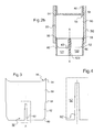
- Figure 2b is a cross sectional of figure 2 and is taken inside the tube 12b which receives baffle 20. This figure shows best the U-shape of cover 40 and collector 36 which are brazed together along the respective branches of their U-shape.
- tubes 12 of the described embodiment have two channels 121 and 122 which are separated by a wall 123 having an axis of symmetry X-X.
- upper portion 50 of baffle 20 has edges 54 each with a rounding 56 which accommodates the rounded portion of cover 40 at the corners of the U-shape. This allows for better brazing.
- lower portion 52 of baffle 20 is connected to upper portion 50 by a tapered portion 58.
- Tapered portion 58 allows for good insertion inside the tube end, and constitutes a stop for the insertion of baffle 20.
- upper portion 50 constitutes a main portion accommodating the inside of header 16 for a well sealed separation
- lower portion 52 constitutes a thinned portion which accommodates the inside of the tube in which it is received.
- Lower portion 52 also comprises cut edges 60, which permit easy mounting of baffle 20 inside tube 12.
- Lower portion 52 further comprises a cutting 62 for accommodating wall member 123 of the tube in which it extends.
- cutting 62 is slightly tapered, such that the lowest portion of cutting 62 is larger than the highest portion of cutting 62. Cutting 62 thus enables good positioning of baffle 20 in tube 12 and insures the mechanical stability of baffle 20 before brazing of the heat exchanger.
- the baffle may comprise several cuttings in order to accommodate tubes with more than two channels, or none should there be only one.
- the above described heat exchanger comprise aluminium headers having a U-shape, all sorts of shape may be used for these headers, as well as a variety of materials including steel, steel alloys or aluminium alloys.
Landscapes
- Engineering & Computer Science (AREA)
- Physics & Mathematics (AREA)
- Thermal Sciences (AREA)
- Mechanical Engineering (AREA)
- General Engineering & Computer Science (AREA)
- Heat-Exchange Devices With Radiators And Conduit Assemblies (AREA)
Abstract
Description
- The invention is concerned with a heat exchanger for an automotive vehicle comprising a beam of tubes received at one end in a header. The header comprises first and second chambers for circulating respective fluids, which are separated by separating means.
- Multiple chambers heat exchangers are known for circulating a first fluid at a relatively high temperature in a first chamber, and a second fluid at a relatively low temperature in a second chamber. Those exchangers can particularly be radiators, and are affected by various and specific problems.
- Amongst these problems is the difficulty of manufacturing a reliable and resistant separation between the two compartments of the exchanger. Another problem encountered is the strength of the portion separating the two compartments, and the general strength of the radiator due to the high strains induced by the temperature gradient of the fluids circulating therethrough.
-
US 6 942 014 teaches a heat exchanger in which a double separating wall member is introduced in a header for defining two chambers. The two chambers and their respective associated tubes define two compartments. This design has shown reliability flaws of the separation element between the two chambers, as well as mechanical break problems of this element due to the temperature gradient surrounding it. -
EP 0 789 213 teaches a heat exchanger in which two separation wall members are introduced in the header, with some tubes connected to the portion of the header comprised between the separation wall members. This solution is expensive and impractical in terms of design and industrialization, and it does not allow for good performance of the exchanger. -
US 6 883 600 teaches a similar heat exchanger, in which the design of the baffles is modified to improve their brazeability with the header. The baffles are not simple plate anymore and their edges are folded to have a better contact area with the tank. A part of the tank flange is cut to allow an approach area for introducing the baffles in the tank. This solution is also expensive and impractical in terms of design and industrialization, and it does not allow for good performance of the exchanger. - The invention aims at improving the situation.
- A heat exchanger for an automotive vehicle is proposed, comprising a beam of tubes received at one end in a header, said header comprising first and second chambers for circulating respective fluids, and said chambers being separated by separating means. In this heat exchanger, said separating means comprise a baffle extending within a tube end received in said header.
- By using a baffle disposed within a tube end, this exchanger allows for better performance by not having dummy tubes. Moreover, there is no need for particular manufacturing of the header or of the tubes, since the baffle can be adapted on regular heat exchangers. This allows for higher productivity, and lowers mounting times and production and design costs.
- Finally, the baffle portion extending within said tube end reinforces the tube portion which suffers the most stress, thus insuring high reliability and strength of the exchanger, while insuring good separation of the chambers.
- In this heat exchanger, the first and second chambers may be arranged to receive respective fluids having respective first and second selected temperature ranges, the second selected temperature range being lower than the first selected temperature range. Said baffle may be disposed within the tube end received in the second chamber which is closest to said first chamber.
- In one embodiment, the baffle may extend into the tube portion outside of said header, which allows for better reinforcement of the receiving tube end.
- In another embodiment, the baffle comprises a main portion to adapt the header and a thinned portion to settle in the tube end in which it is received. The main portion and the thinned portion may be separated by a tapered portion.
- Thus, there need not be any specific arrangement to maintain the baffle in place before brazing, which further lowers mounting times and production and design costs.
- In yet another embodiment, the tube receiving said baffle has two channels separated by a wall member, and the baffle comprises a cutting to settle in said wall member.
- This allows for improved heat transfer and tube design, while insuring that there need not be any specific arrangement to maintain the baffle in place before brazing.
- In another embodiment, the header comprises a cover and a collector having respective shapes, and the baffle comprises edges accommodating the shape of the cover. More specifically, the cover may have a U-shaped cross section, and the edges of said baffle may comprise a rounding for accommodating the corners of the U-shaped cross section. This allows for high reliability of the separation between said chambers.
- The heat exchanger may be made of aluminium, steel or an aluminium or steel alloy.
- Further advantages and characteristics will appear more clearly in the following specification, given by way of illustration and in a non limiting manner, of embodiments based on the drawings on which:
-
Figure 1 shows a general face view of a heat exchanger according to the invention; -
Figure 2a shows a longitudinal sectional view of details offigure 1 ; -
Figure 2b shows cross sectional view offigure 2 ; -
Figure 3 shows a plan view of a baffle offigure 1 ; and -
Figure 4 shows a plan view of detail IV offigure 3 . -
Figure 1 shows a heat exchanger comprising abeam 10, comprised of a number of tubes 12 extending mutually in a substantially parallel manner between whichcooling fins 14 are disposed. - The tubes 12 discharge at one end into a
header 16, and, at another end into aheader 18.Headers header collector - All the components of this exchanger, that is tubes 12,
fins 14 andheaders - The beam is divided into a part A forming a cooler of a first fluid and comprised of
tubes 12a, and a part B forming a cooler of a second fluid and comprising oftubes 12b. - Tubes 12a are adapted to be circulated by a first fluid F1 such as water.
Tubes 12b are adapted to be circulated by a second fluid F2, for example antifreeze. It will be understood that the two fluids circulating in both parts of the beam will be cooler by the same flow of air. - In order to separate both fluids,
headers divides header 16 into afirst chamber 24 for fluid F1 and asecond chamber 26 for fluid F2. Similarly, separating means 22divide header 18 into afirst chamber 28 for fluid F1 and into asecond chamber 30 for fluid F2. - Fluid F1 enters
first chamber 24 by aninlet tube portion 32, circulates intubes 12a via a parallel flow and reachessecond chamber 28 before output by anoutlet tube portion 34. - Fluid F2 enters
second chamber 26 by an inlet tube portion, circulates intubes 12b via a parallel flow and reachessecond chamber 30 before output by an outlet tube portion. -
Figure 2a shows a longitudinal sectional view of detail II offigure 1 .Header 16 is comprised of acover 40 and of acollector 36. In the described embodiment,cover 40 andcollector 36 are both made of aluminium and are brazed together. These elements could be made out of another metal, such as steel, or out of an aluminium or steel alloy. - Detail II shows the adjacent ends of
first chamber 24 andsecond chamber 26 are shown, as well as separatingmeans 20, which will be described in further detail below. As mentioned above, first fluid F1 is water, and second fluid F2 is antifreeze in this embodiment, the former having a much higher temperature than the latter. - Fluids F1 and F2 could also be identical (that is water or antifreeze for both
chambers 24 and 26), but they could have different temperatures due to the fact that they could originate from different parts of the cooling circuit of the automotive vehicle. As a new embodiment not shown in the appended drawings, it is possible to provide counter flow fluids, i.e. that inlet F1 is set on the opposite side than inlet F2. -
Collector 36 has a plurality ofopenings 44 which receive tubes 12. Separating means 20 are realized as a baffle which extends partially within a tube.
In anupper portion 50,baffle 20 fills the whole section comprised betweencover 40 andcollector 36, and effectively separatesheader 16 intochambers - In a
lower portion 52,baffle 20 extends through a tube until a portion of this tube that is lower than the lower part ofheader 16. - That is, when the heat exchanger is brazed, baffle 20 constitutes a reinforcement of the tube in which it is received in its small radius. This way, the
tube receiving baffle 20 is effectively reinforced to resist the temperature gradient around it. - Researches by the applicant have shown that in such designs, the tube which suffers the most stress is the first tube of the chamber circulating the fluid with the lowest temperature.
-
Baffle 20 is thus received in thefirst tube 12b ofchamber 26, and it is placed against the wall oftube 12b which is in contact withchamber 24. In this arrangement, baffle 20 separates effectivelychambers - As appears on
figure 2a , baffle 20 occupies part of the output section of the tube end in which it is received. This allows the strengthening of the tube radius against thermal stress, while insuring that the tube which receivesbaffle 20 is not rendered dummy. As a possibility with the invention, thebaffle 20 occupies from 20% up to 100% of the output section of the tube end and more advantageously, up to 50% of the output section of the tube. We have noted that in this last range, the decrease of performance of the heat exchanger (dummy tubes) was not relevant. -
Figure 2b is a cross sectional offigure 2 and is taken inside thetube 12b which receivesbaffle 20. This figure shows best the U-shape ofcover 40 andcollector 36 which are brazed together along the respective branches of their U-shape. - As appears on this figure, tubes 12 of the described embodiment have two
channels wall 123 having an axis of symmetry X-X. - Reference will now be made to
figure 3 and 4 which best show the baffle offigure 2a and2b . - As shown on
figures 2a and3 ,upper portion 50 ofbaffle 20 hasedges 54 each with a rounding 56 which accommodates the rounded portion ofcover 40 at the corners of the U-shape. This allows for better brazing. - At the other end,
lower portion 52 ofbaffle 20 is connected toupper portion 50 by a taperedportion 58.Tapered portion 58 allows for good insertion inside the tube end, and constitutes a stop for the insertion ofbaffle 20. - As such,
upper portion 50 constitutes a main portion accommodating the inside ofheader 16 for a well sealed separation, whilelower portion 52 constitutes a thinned portion which accommodates the inside of the tube in which it is received. -
Lower portion 52 also comprises cutedges 60, which permit easy mounting ofbaffle 20 inside tube 12.Lower portion 52 further comprises a cutting 62 for accommodatingwall member 123 of the tube in which it extends. - As seen on
figure 4 , cutting 62 is slightly tapered, such that the lowest portion of cutting 62 is larger than the highest portion of cutting 62.Cutting 62 thus enables good positioning ofbaffle 20 in tube 12 and insures the mechanical stability ofbaffle 20 before brazing of the heat exchanger. - The above specification shall not be interpreted as a restricting description of the invention. More specifically, the scope of the invention comprises all alternatives which will readily appear to the man skilled in the art.
For example, the baffle may comprise several cuttings in order to accommodate tubes with more than two channels, or none should there be only one. Also, while the above described heat exchanger comprise aluminium headers having a U-shape, all sorts of shape may be used for these headers, as well as a variety of materials including steel, steel alloys or aluminium alloys. - The scope of the invention is to be defined by the following claims.
Claims (10)
- Heat exchanger for an automotive vehicle comprising a beam of tubes (12) received at one end in a header, said header (16) comprising first (24) and second (26) chambers for circulating respective fluids, and said chambers (24, 26) being separated by separating means (20, 22), characterized in that said separating means (20, 22) comprise a baffle (20) extending within a selected tube end (12b) received in said header (16) while allowing fluid to circulate therethrough.
- Heat exchanger according to claim 1, characterized in that the first and second chambers (24, 26) are arranged to receive respective fluids (F1, F2) having respective first and second selected temperature ranges, the second selected temperature range being lower than the first selected temperature range, and that said selected tube end (12b) is the tube end received in the second chamber (26) which is closest to said first chamber (24).
- Heat exchanger according to claim 1 or 2, characterized in that said baffle (20) extends into the tube portion outside of said header (16).
- Heat exchanger according to any of the preceding claims, characterized in that the baffle (20) comprises a main portion (50) to adapt the header (16) and a thinned portion (52) to settle in the selected tube end (12b).
- Heat exchanger according to claim 4, wherein said main portion (50) and said thinned portion (52) are separated by a tapered portion (58).
- Heat exchanger according to any of the preceding claims, characterized in that the selected tube end has two channels (121, 122) separated by a wall member (123), and that said baffle (20) comprises a cutting (62) to settle in said wall member (123).
- Heat exchanger according to any of the preceding claims, characterized in that said header (16) comprises a cover (40) and a collector (36) having respective shapes, and that said baffle (20) comprises edges (54) accommodating the shape of the cover (40).
- Heat exchanger according to claim 7, characterized in that said cover (40) has a U-shaped cross section, and that said edges (54) of said baffle (20) comprise a rounding (56) for accommodating the corners of the U-shaped cross section.
- Heat exchanger according to any of the preceding claims, characterized in that said baffle (20) has a cross section area equal to XX of the selected tube end output flow area.
- Heat exchanger according to any of the preceding claims, characterized in that it is made of aluminium, steel or an aluminium or steel alloy.
Priority Applications (2)
| Application Number | Priority Date | Filing Date | Title |
|---|---|---|---|
| EP07460004A EP1962044A1 (en) | 2007-02-23 | 2007-02-23 | Improved heat exchanger for an automotive vehicle |
| PCT/EP2008/050561 WO2008101755A1 (en) | 2007-02-23 | 2008-01-18 | Improved heat exchanger for an automotive vehicle |
Applications Claiming Priority (1)
| Application Number | Priority Date | Filing Date | Title |
|---|---|---|---|
| EP07460004A EP1962044A1 (en) | 2007-02-23 | 2007-02-23 | Improved heat exchanger for an automotive vehicle |
Publications (1)
| Publication Number | Publication Date |
|---|---|
| EP1962044A1 true EP1962044A1 (en) | 2008-08-27 |
Family
ID=38335637
Family Applications (1)
| Application Number | Title | Priority Date | Filing Date |
|---|---|---|---|
| EP07460004A Withdrawn EP1962044A1 (en) | 2007-02-23 | 2007-02-23 | Improved heat exchanger for an automotive vehicle |
Country Status (2)
| Country | Link |
|---|---|
| EP (1) | EP1962044A1 (en) |
| WO (1) | WO2008101755A1 (en) |
Cited By (2)
| Publication number | Priority date | Publication date | Assignee | Title |
|---|---|---|---|---|
| US20140007612A1 (en) * | 2012-07-06 | 2014-01-09 | Samsung Electronics Co., Ltd. | Refrigerator and heat exchanger for the same |
| CN104746644A (en) * | 2013-12-26 | 2015-07-01 | 青岛安装建设股份有限公司 | Internal and external double annular steel tube support seat |
Families Citing this family (1)
| Publication number | Priority date | Publication date | Assignee | Title |
|---|---|---|---|---|
| CN108954922A (en) * | 2018-08-28 | 2018-12-07 | 珠海格力电器股份有限公司 | Microchannel heat exchanger and air conditioner |
Citations (6)
| Publication number | Priority date | Publication date | Assignee | Title |
|---|---|---|---|---|
| JPS63127091A (en) * | 1986-11-18 | 1988-05-30 | Toyo Radiator Kk | Method of connecting tank with pipe |
| US4960169A (en) * | 1989-06-20 | 1990-10-02 | Modien Manufacturing Co. | Baffle for tubular heat exchanger header |
| JPH02302592A (en) * | 1989-05-15 | 1990-12-14 | Nippondenso Co Ltd | Heat exchanger |
| US5299635A (en) * | 1993-03-05 | 1994-04-05 | Wynn's Climate Systems, Inc. | Parallel flow condenser baffle |
| US5318111A (en) * | 1993-06-22 | 1994-06-07 | Ford Motor Company | Integral baffle assembly for parallel flow heat exchanger |
| EP1557630A1 (en) * | 2004-01-23 | 2005-07-27 | BEHR Lorraine S.A.R.L. | Heat exchanger |
-
2007
- 2007-02-23 EP EP07460004A patent/EP1962044A1/en not_active Withdrawn
-
2008
- 2008-01-18 WO PCT/EP2008/050561 patent/WO2008101755A1/en not_active Ceased
Patent Citations (6)
| Publication number | Priority date | Publication date | Assignee | Title |
|---|---|---|---|---|
| JPS63127091A (en) * | 1986-11-18 | 1988-05-30 | Toyo Radiator Kk | Method of connecting tank with pipe |
| JPH02302592A (en) * | 1989-05-15 | 1990-12-14 | Nippondenso Co Ltd | Heat exchanger |
| US4960169A (en) * | 1989-06-20 | 1990-10-02 | Modien Manufacturing Co. | Baffle for tubular heat exchanger header |
| US5299635A (en) * | 1993-03-05 | 1994-04-05 | Wynn's Climate Systems, Inc. | Parallel flow condenser baffle |
| US5318111A (en) * | 1993-06-22 | 1994-06-07 | Ford Motor Company | Integral baffle assembly for parallel flow heat exchanger |
| EP1557630A1 (en) * | 2004-01-23 | 2005-07-27 | BEHR Lorraine S.A.R.L. | Heat exchanger |
Cited By (3)
| Publication number | Priority date | Publication date | Assignee | Title |
|---|---|---|---|---|
| US20140007612A1 (en) * | 2012-07-06 | 2014-01-09 | Samsung Electronics Co., Ltd. | Refrigerator and heat exchanger for the same |
| CN104746644A (en) * | 2013-12-26 | 2015-07-01 | 青岛安装建设股份有限公司 | Internal and external double annular steel tube support seat |
| CN104746644B (en) * | 2013-12-26 | 2018-01-02 | 青岛安装建设股份有限公司 | A kind of internal and external double-circular shape steel pipe bearing |
Also Published As
| Publication number | Publication date |
|---|---|
| WO2008101755A1 (en) | 2008-08-28 |
Similar Documents
| Publication | Publication Date | Title |
|---|---|---|
| EP0643278B1 (en) | An evaporator for use in car coolers | |
| US10337808B2 (en) | Condenser | |
| US6904965B2 (en) | Radiator with side flat tubes | |
| JP5985600B2 (en) | Reinforce connection between heat exchanger plates | |
| EP1956331A2 (en) | Heat exchanger | |
| JP5408951B2 (en) | Refrigerant evaporator and air conditioner using the same | |
| EP3134696B1 (en) | Vehicle heat exchanger tube and vehicle radiator comprising such a tube | |
| JP2004225961A (en) | Multi-flow heat exchanger | |
| JPH0245945B2 (en) | ||
| CN108709445B (en) | Cooling heat exchanger | |
| US20060254757A1 (en) | Intermediate cooler for air-conditioning refrigerant | |
| WO2008101755A1 (en) | Improved heat exchanger for an automotive vehicle | |
| JPS63271099A (en) | Heat exchanger | |
| US20090159253A1 (en) | Heat exchanger tubes and combo-coolers including the same | |
| EP2375208A1 (en) | Improved heat exchanger | |
| JP2007078292A (en) | Heat exchanger and double heat exchanger | |
| JP2018194179A (en) | Heat exchanger | |
| EP3825634B1 (en) | A reinforcement for a heat exchanger | |
| EP3825635A1 (en) | A reinforcement for a heat exchanger | |
| JP2019138507A (en) | Evaporator with cold storage function | |
| EP1887295B1 (en) | Condenser with an improved tank | |
| JPH0581826B2 (en) | ||
| US20240410654A1 (en) | Heat exchanger assembly for a motor vehicle | |
| KR100666927B1 (en) | Header Type Heat Exchanger | |
| JP2003106793A (en) | Heat exchanger |
Legal Events
| Date | Code | Title | Description |
|---|---|---|---|
| PUAI | Public reference made under article 153(3) epc to a published international application that has entered the european phase |
Free format text: ORIGINAL CODE: 0009012 |
|
| AK | Designated contracting states |
Kind code of ref document: A1 Designated state(s): AT BE BG CH CY CZ DE DK EE ES FI FR GB GR HU IE IS IT LI LT LU LV MC NL PL PT RO SE SI SK TR |
|
| AX | Request for extension of the european patent |
Extension state: AL BA HR MK RS |
|
| 17P | Request for examination filed |
Effective date: 20090227 |
|
| 17Q | First examination report despatched |
Effective date: 20090403 |
|
| AKX | Designation fees paid |
Designated state(s): AT BE BG CH CY CZ DE DK EE ES FI FR GB GR HU IE IS IT LI LT LU LV MC NL PL PT RO SE SI SK TR |
|
| STAA | Information on the status of an ep patent application or granted ep patent |
Free format text: STATUS: THE APPLICATION IS DEEMED TO BE WITHDRAWN |
|
| 18D | Application deemed to be withdrawn |
Effective date: 20090814 |