EP1961629A2 - Detection device for vehicles - Google Patents
Detection device for vehicles Download PDFInfo
- Publication number
- EP1961629A2 EP1961629A2 EP20080151220 EP08151220A EP1961629A2 EP 1961629 A2 EP1961629 A2 EP 1961629A2 EP 20080151220 EP20080151220 EP 20080151220 EP 08151220 A EP08151220 A EP 08151220A EP 1961629 A2 EP1961629 A2 EP 1961629A2
- Authority
- EP
- European Patent Office
- Prior art keywords
- cap
- cap according
- component
- locking device
- sensor
- Prior art date
- Legal status (The legal status is an assumption and is not a legal conclusion. Google has not performed a legal analysis and makes no representation as to the accuracy of the status listed.)
- Granted
Links
- 238000001514 detection method Methods 0.000 title claims description 10
- 239000002828 fuel tank Substances 0.000 claims abstract description 16
- 238000010168 coupling process Methods 0.000 claims description 13
- 238000005859 coupling reaction Methods 0.000 claims description 13
- 239000000945 filler Substances 0.000 claims description 12
- 230000008878 coupling Effects 0.000 claims description 10
- 230000005284 excitation Effects 0.000 claims description 6
- 238000004891 communication Methods 0.000 claims description 5
- 230000005540 biological transmission Effects 0.000 claims description 4
- 230000005355 Hall effect Effects 0.000 claims description 2
- 235000014676 Phragmites communis Nutrition 0.000 claims description 2
- 239000000696 magnetic material Substances 0.000 claims description 2
- 230000003287 optical effect Effects 0.000 claims description 2
- 239000000446 fuel Substances 0.000 description 5
- 238000000034 method Methods 0.000 description 4
- 230000008859 change Effects 0.000 description 3
- 238000010586 diagram Methods 0.000 description 2
- 238000006073 displacement reaction Methods 0.000 description 2
- 230000007246 mechanism Effects 0.000 description 2
- 230000002093 peripheral effect Effects 0.000 description 2
- 239000012815 thermoplastic material Substances 0.000 description 2
- 230000009471 action Effects 0.000 description 1
- 238000004026 adhesive bonding Methods 0.000 description 1
- 230000015572 biosynthetic process Effects 0.000 description 1
- 238000010276 construction Methods 0.000 description 1
- 239000013536 elastomeric material Substances 0.000 description 1
- 239000007788 liquid Substances 0.000 description 1
- 239000007769 metal material Substances 0.000 description 1
- 239000004033 plastic Substances 0.000 description 1
- 238000009877 rendering Methods 0.000 description 1
- 230000000717 retained effect Effects 0.000 description 1
- 230000000630 rising effect Effects 0.000 description 1
- XLYOFNOQVPJJNP-UHFFFAOYSA-N water Substances O XLYOFNOQVPJJNP-UHFFFAOYSA-N 0.000 description 1
- 238000003466 welding Methods 0.000 description 1
Images


Classifications
-
- B—PERFORMING OPERATIONS; TRANSPORTING
- B60—VEHICLES IN GENERAL
- B60K—ARRANGEMENT OR MOUNTING OF PROPULSION UNITS OR OF TRANSMISSIONS IN VEHICLES; ARRANGEMENT OR MOUNTING OF PLURAL DIVERSE PRIME-MOVERS IN VEHICLES; AUXILIARY DRIVES FOR VEHICLES; INSTRUMENTATION OR DASHBOARDS FOR VEHICLES; ARRANGEMENTS IN CONNECTION WITH COOLING, AIR INTAKE, GAS EXHAUST OR FUEL SUPPLY OF PROPULSION UNITS IN VEHICLES
- B60K15/00—Arrangement in connection with fuel supply of combustion engines or other fuel consuming energy converters, e.g. fuel cells; Mounting or construction of fuel tanks
- B60K15/03—Fuel tanks
- B60K15/04—Tank inlets
- B60K15/0406—Filler caps for fuel tanks
- B60K15/0409—Provided with a lock
-
- B—PERFORMING OPERATIONS; TRANSPORTING
- B60—VEHICLES IN GENERAL
- B60K—ARRANGEMENT OR MOUNTING OF PROPULSION UNITS OR OF TRANSMISSIONS IN VEHICLES; ARRANGEMENT OR MOUNTING OF PLURAL DIVERSE PRIME-MOVERS IN VEHICLES; AUXILIARY DRIVES FOR VEHICLES; INSTRUMENTATION OR DASHBOARDS FOR VEHICLES; ARRANGEMENTS IN CONNECTION WITH COOLING, AIR INTAKE, GAS EXHAUST OR FUEL SUPPLY OF PROPULSION UNITS IN VEHICLES
- B60K15/00—Arrangement in connection with fuel supply of combustion engines or other fuel consuming energy converters, e.g. fuel cells; Mounting or construction of fuel tanks
- B60K15/03—Fuel tanks
- B60K15/04—Tank inlets
- B60K15/0406—Filler caps for fuel tanks
-
- G—PHYSICS
- G01—MEASURING; TESTING
- G01R—MEASURING ELECTRIC VARIABLES; MEASURING MAGNETIC VARIABLES
- G01R33/00—Arrangements or instruments for measuring magnetic variables
- G01R33/02—Measuring direction or magnitude of magnetic fields or magnetic flux
- G01R33/06—Measuring direction or magnitude of magnetic fields or magnetic flux using galvano-magnetic devices
- G01R33/07—Hall effect devices
-
- B—PERFORMING OPERATIONS; TRANSPORTING
- B60—VEHICLES IN GENERAL
- B60K—ARRANGEMENT OR MOUNTING OF PROPULSION UNITS OR OF TRANSMISSIONS IN VEHICLES; ARRANGEMENT OR MOUNTING OF PLURAL DIVERSE PRIME-MOVERS IN VEHICLES; AUXILIARY DRIVES FOR VEHICLES; INSTRUMENTATION OR DASHBOARDS FOR VEHICLES; ARRANGEMENTS IN CONNECTION WITH COOLING, AIR INTAKE, GAS EXHAUST OR FUEL SUPPLY OF PROPULSION UNITS IN VEHICLES
- B60K15/00—Arrangement in connection with fuel supply of combustion engines or other fuel consuming energy converters, e.g. fuel cells; Mounting or construction of fuel tanks
- B60K15/03—Fuel tanks
- B60K2015/0319—Fuel tanks with electronic systems, e.g. for controlling fuelling or venting
- B60K2015/03197—Systems for exchanging data
-
- B—PERFORMING OPERATIONS; TRANSPORTING
- B60—VEHICLES IN GENERAL
- B60K—ARRANGEMENT OR MOUNTING OF PROPULSION UNITS OR OF TRANSMISSIONS IN VEHICLES; ARRANGEMENT OR MOUNTING OF PLURAL DIVERSE PRIME-MOVERS IN VEHICLES; AUXILIARY DRIVES FOR VEHICLES; INSTRUMENTATION OR DASHBOARDS FOR VEHICLES; ARRANGEMENTS IN CONNECTION WITH COOLING, AIR INTAKE, GAS EXHAUST OR FUEL SUPPLY OF PROPULSION UNITS IN VEHICLES
- B60K15/00—Arrangement in connection with fuel supply of combustion engines or other fuel consuming energy converters, e.g. fuel cells; Mounting or construction of fuel tanks
- B60K15/03—Fuel tanks
- B60K2015/03328—Arrangements or special measures related to fuel tanks or fuel handling
- B60K2015/03434—Arrangements or special measures related to fuel tanks or fuel handling for preventing theft of fuel
-
- Y—GENERAL TAGGING OF NEW TECHNOLOGICAL DEVELOPMENTS; GENERAL TAGGING OF CROSS-SECTIONAL TECHNOLOGIES SPANNING OVER SEVERAL SECTIONS OF THE IPC; TECHNICAL SUBJECTS COVERED BY FORMER USPC CROSS-REFERENCE ART COLLECTIONS [XRACs] AND DIGESTS
- Y10—TECHNICAL SUBJECTS COVERED BY FORMER USPC
- Y10T—TECHNICAL SUBJECTS COVERED BY FORMER US CLASSIFICATION
- Y10T70/00—Locks
- Y10T70/50—Special application
- Y10T70/5093—For closures
- Y10T70/554—Cover, lid, cap, encasing shield
- Y10T70/5562—Removable
- Y10T70/5571—Freely movable when locked
-
- Y—GENERAL TAGGING OF NEW TECHNOLOGICAL DEVELOPMENTS; GENERAL TAGGING OF CROSS-SECTIONAL TECHNOLOGIES SPANNING OVER SEVERAL SECTIONS OF THE IPC; TECHNICAL SUBJECTS COVERED BY FORMER USPC CROSS-REFERENCE ART COLLECTIONS [XRACs] AND DIGESTS
- Y10—TECHNICAL SUBJECTS COVERED BY FORMER USPC
- Y10T—TECHNICAL SUBJECTS COVERED BY FORMER US CLASSIFICATION
- Y10T70/00—Locks
- Y10T70/50—Special application
- Y10T70/5093—For closures
- Y10T70/554—Cover, lid, cap, encasing shield
- Y10T70/5562—Removable
- Y10T70/5575—Directly seating
- Y10T70/558—Cover-carried lock
Definitions
- the present invention relates to a detection device for vehicles and, more particularly, to a removable cap designed to occlude a filler of a fuel tank of a vehicle.
- a cap of this type basically comprises a gripping portion, facing the outside of the filler of the fuel tank, and a locking or clamping portion, having coupling means which designed for co-operating with coupling means provided at the filler of the fuel tank.
- the coupling means referred to above are usually of a threaded or bayonet-coupling type.
- the cap then comprises a locking device, which can be switched between a closing condition and an opening condition and comprises a component with a seat for a respective key.
- the device is operatively set between the gripping portion and the locking portion of the cap in such a way that, in the closing condition, a rotation movement imparted manually upon the gripping portion does not enable disengagement of the locking portion from the corresponding seat. Instead, in the opening condition of the locking device, the aforesaid rotation movement enables disengagement of the locking portion from its seat.
- Key-operated caps are effective in the case of vehicles for private use, but are not completely suitable for preventing fraudulent removal of fuel from a vehicle to which a plurality of authorized persons have access.
- An example is the case of haulage companies, car-rental firms and, more in general, all those organizations that have available vehicles that are normally used by different people.
- an authorized driver, or at least the person who has the keys of the vehicle at his disposal can easily open the fuel tank and fraudulently remove therefrom part of the contents.
- An example of fraud understood in this sense is the case in which the fuel that has been removed is replaced with another liquid, for example water.
- GB-A-2343283 describes a remote detection system of this type.
- the movement of the cap is detected by a sensor, and a transmitter circuit consequently sends an alarm signal to a control unit.
- a part of the detection system is integrated in the gripping portion of the cap.
- the locking device is designed in such a way that, when the device itself is in the closing condition, the gripping portion is free to rotate even though this does not enable removal of the cap from the filler of the fuel tank and hence removal of fuel: this fact may be the source of false alarms. For instance, if the vehicle is in parked and somebody, for any reason, turns the cap, the system generates an alarm signal, even though in actual fact the cap has not been removed from the filler of the fuel tank and no fraudulent action or removal of fuel is in progress.
- the purpose of present invention is basically to solve the drawbacks referred to, in a simple, reliable, and inexpensive way. Said purpose is achieved, according to the present invention, by a removable cap for vehicles, which presents the characteristics specified in the annexed claims.
- the claims form an integral part of the technical teaching provided herein in relation to the invention.
- the reference number 1 designates as a whole a cap according to the present invention, designed to occlude the filler of a fuel tank of a motor vehicle, such as, for example, a lorry or a bus.
- the cap 1 comprises a first, gripping, portion, which in use is positioned on the outside of the filler of the fuel tank, and a second, locking, portion, designed to couple with the aforesaid filler.
- the aforesaid gripping portion comprises a main body, designated by 3, which has a substantially cylindrical shape, with a bottom wall 3a and a peripheral wall 3b on which gripping projections 3c are formed.
- the wall 3a and an end part of the wall 3b delimit a seat 3d, for housing an electronic circuit 4, such as a printed circuit, comprising a plurality of electrical/electronic components.
- the circuit 4 has a substantially annular configuration, corresponding to that of the seat 3d. From the bottom of the seat 3d there rise projections 3e for positioning the circuit 4, which is purposely provided with respective seats or through holes 4a.
- the projections 3e are moreover exploited for fixing or positioning of a lid 5 for closing in a sealed way the seat 3d, which completes the aforesaid first part of the cap 1.
- the body 3 and the lid 5 are, for example, made of moulded thermoplastic material.
- the seal can be guaranteed by means of the interposition of at least one gasket (not represented) set between the lid 5 and the body 3, which are, for example, engaged or screwed together, or else by welding or gluing of the lid 5 on the body 3, or with any other known technique suitable for the purpose.
- a generally tubular portion defined in the central region of the body 3 is a generally tubular portion, the upper part 6a of which projects within the seat 3d.
- the top end of the part 6a is designed to engage a central through hole 5a of the lid 5.
- the lower part 6b of the aforesaid tubular portion projects, instead, within a lower cavity 3f of the body 3, which is also delimited by the wall 3a and by a respective portion of the wall 3b.
- the lower part 6b of the aforesaid tubular portion is surrounded by a generally cylindrical hollow formation 3g of the body 3, which is located within an area of the cavity 3f circumscribed by a wall 3h, the latter rising from the wall 3a and being concentric to the wall 3b.
- the aforesaid locking portion of the cap 1 comprises, in the example provided, an intermediate body 8 and an end body 9, set between which is an annular gasket 7, made, for example, of elastomeric material.
- the intermediate body 8 made, for example, of moulded thermoplastic material, has a circular base 8a, projecting from the lower part of which is an axially hollow cylindrical portion 8b, which has a seat or an internal axial groove, designated by 8c in Figure 4 , which is designed to receive an engaging projection of a key-locking mechanism or device.
- the end body 9, which is preferably made of metal material, is designed to be mechanically coupled to the cylindrical portion 8b, in a known way.
- the body 9 has a generally annular configuration and defines on the respective peripheral wall two radial appendages 9a.
- Said appendages 9a provide engagement means, which are designed to co-operate with respective engagement means provided in the filler of the fuel tank, in order to constitute therewith a substantially bayonet-type coupling system.
- the appendages 9a can be replaced by a threaded attachment or an attachment of some other suitable type.
- the central part of the body 9, designated by 9b is substantially tubular and configured for being rendered fixed, in a known way, with respect to the portion 8b of the intermediate body 8, for example, by means of internal projections 9c, which engage in respective seats made on the portion 8b, not represented in Figure 3 (but one of which is partially visible in Figure 5 ).
- the aforesaid seats on the portion 8b are shaped like axial grooves, in order to enable a certain degree of freedom in the axial direction for the body 9 to allow for any possible compensation of tolerances, but are such as to constrain it in its rotary movement, i.e., in the direction of opening and closing of the cap.
- the locking portion of the cap 1 can possibly comprise a terminal, fixed to the end of the cylindrical portion 8b of the body 8, with a spring set between said terminal and the body 9, so as to force the latter, together with the body 8, in the direction of the body 3.
- Designated as a whole by 10 is the key-locking device already referred to above, which is of a general conception in itself known in the sector, and hence is illustrated only schematically and described briefly as regards a possible embodiment thereof.
- the device 10 can be of the type having a first component, designated by 10a, projecting from which in a radial direction are movable pins (not represented), which can be operated with a respective key.
- a seat 10c for the key is provided for said purpose.
- the component 10a is coupled so that it can turn freely on a second component 10b of the device 10.
- the cavity of the tubular portion 6a-6b has a restriction, defining a contrast surface for a top flange part of the component 10a, whilst the component 10b is constrained to the intermediate body 8, within the cavity of the corresponding tubular portion 8b.
- the bodies 3 and 8 are joined to one another in a rotatable way.
- the device 10 can also be without a component rendered fixed with respect to the part 8, for example, in the case where - as mentioned above - the locking portion of the cap comprises a terminal, fixed to the end of the cylindrical portion 8b of the body 8, with a spring set between said terminal and the body 9.
- the aforesaid pins mechanically engage the component 10a to the main body 3.
- the key When the key is inserted in the locking device 10, it causes displacement of the aforesaid pins towards the inside of the component 10a.
- the component 10a hence becomes rotatable in the body 3, but without being able to perform complete rotations (for example, only up to approximately 350°).
- appropriate projections and detents are made in the component 10a and in the body 3, in accordance with a technique being in itself known in the field.
- the component 10a is provided with a cam profile, which, in the relative rotation between the component 10a and the body 3, radially displaces a further movable component of the locking device 10, which couples (or not, according to the movement imparted by the key) with the seat 8c of the intermediate body 8.
- the bodies 3 and 8 are rendered fixed with respect to one another in rotation by means of the aforesaid further component.
- the further component is not coupled to the seat 8c, with the body 3 that can hence rotate, but without transferring its own movement to the body 8.
- the device 10 is configured in such a way that, in the respective closing condition, any manual rotation imparted on the body 3 cannot be transferred to the body 8.
- the radial appendages 9a of the body 9 consequently cannot be uncoupled from the part of the bayonet-coupling system formed in the mouth of the fuel tank, thus rendering removal of the cap 1 impossible.
- a possible manual rotation imparted on the body 3 can be transferred to the body 8, with the radial appendages 9a of the body 9 that can be disengaged from the part of the bayonet-coupling system formed in the mouth of the fuel tank, thus enabling removal of the cap 1.
- the general configuration of the device 10 is such that at least the component 10a is free to turn with the body 3, and switching of the device between the conditions of closing and opening can be obtained only by moving said component 10a angularly with respect to the body 3, between a first predefined position and a second predefined position. Said angular movement can be obtained only by inserting the key in the component 10a, the above according a technique known in itself.
- the cap 1 is provided with means for detecting the aforesaid relative angular movement between the body 3 and the component 10a of the locking device 10.
- the detection means comprise an excitation element, carried by the component 10a, and a sensor, which can be excited by means of the aforesaid excitation element, carried by the body 3.
- the excitation element is represented by a body made of magnetic material, designated in the figures by 11, which is positioned in a respective seat 12 formed in the component 10a of the locking device 10.
- the detector is constituted by a magnetic sensor, designated by 13, of a type in itself known, such as, for example, a Hall-effect sensor or a reed sensor, belonging to the circuit 4.
- the sensor 13 is mounted in a position at a side of the component 10a.
- the sensor 13 projects from the printed circuit 4, within a respective housing 14, formed in the wall 3a of the body 3, substantially aligned with the area of possible displacement of the magnetic element 11, in the course of the angular movement of the component 10a.
- the magnetic element 11 is set at a distance from the sensor 13 such that the latter is not excited. Instead, following upon passage of the component 10a into the angular position with respect to the body 3 that corresponds to the opening condition of the device 10, the magnetic element 11 is set facing the sensor 13, so as to be able to excite it.
- the configuration can be reversed or in any case be different, for example, with the magnetic element 11 facing the sensor 13 in the closing condition of the device 10.
- the sensor 13 could have a configuration different from the one exemplified, for example, suitable for surface mounting (SMD), without having to project significantly from the printed circuit 4, or without the need for a purposely provided housing 14.
- the element 11 could be mounted and/or oriented in the most appropriate way, for example in an axial direction instead of in a radial direction with respect to the sensor 13.
- the electronic circuit 4 comprises a control unit CU, preferably with microcontroller or ASIC based, operatively connected to the sensor 13.
- the unit CU is programmed or configured for generating, according to detections made by means of the sensor 13, information or signals, which are, for example encoded ones, which represent the movement of the component 10a with respect to the body 3; i.e., they indicate opening or closing of the locking device 10.
- the electronic circuit 4 comprises a data transceiver operating in wireless mode, in particular in RF mode, of a conception in itself known, which is designated by RT1 and is provided for communicating with an external electronic device RD. Transmission of the information can be governed by the control unit CU, for example following upon a change of state of the sensor 13, or else following upon a request received from the outside, for example from the electronic device RD.
- the electronic device RD can be of a dedicated type and installed on board the vehicle.
- a suitable autonomous supply source represented by one or more batteries DC, for example, of the button type, or else the battery of the vehicle.
- the component 10a turns together with the part 3, and hence the sensor 13 does not make any detection.
- the device 10 is switched into the opening condition with the corresponding key, the component 10a moves angularly with respect to the body 3. Said angular movement is detected by the sensor 13, which generates a signal received by the control unit CU.
- the change of state of the sensor 13 is communicated by the control unit CU, through the transmission means RT1, to the external electronic device RD, which is provided with a data-communication interface RT2 compatible with the transceiver RT1 of the circuit 4.
- the circuit 4 transmits to the device RD the information of opening (and possibly closing) of the cap 1, for example, upon change of state of the sensor 13, or else periodically, for example with a frequency of a few seconds.
- the device RD sends, by means of the corresponding interface RT2, a query command to the circuit 4, by means of the interface RT1 thereof; the query command can be sent periodically, for example with a frequency of a few seconds.
- the control unit CU receives, by means of the respective transceiver RT1, the query command and consequently transmits the information on the state of the sensor 13 (cap open or cap closed) to the device RD, through which the corresponding information can be made explicit or processed and retained in a memory.
- the communication interface i.e., the transceivers RT1 and RT2
- the transceivers RT1 and RT2 can be of a telephone type, such as modems of a cellphone type, and the data transmitted can be in the form of short messages, for example, of the SMS or MMS type.
- the type of the means for detecting the angular movement of the component 10a of the locking device 10 could be different from the one exemplified.
- the detection system could be of an optical type, or else based upon sliding contacts, with modalities of implementation that will appear clear to any person skilled in the field.
- the element for exciting the sensor need not be mounted directly in the key-locking device 10, but can be assembled or form part of a further element, which is in turn associated to or mounted on the device 10.
- a further element could be a plastic ring with a magnet 11, or else a magnetic element having an annular shape, or again an element made of plastoferrite, for example, moulded directly on the movable component of the locking device, etc.
- the general structure of the cap and of its key-locking mechanism may be different from what is illustrated herein purely by way of example, without thereby departing from the characteristics specified in the ensuing Claim 1. It is pointed out, in particular, that the locking or clamping portion of the cap can be of type equipped with threaded means, which are able to engage with an internal screw made in the filler of the fuel tank.
Landscapes
- Engineering & Computer Science (AREA)
- Physics & Mathematics (AREA)
- Life Sciences & Earth Sciences (AREA)
- Sustainable Energy (AREA)
- Chemical & Material Sciences (AREA)
- Combustion & Propulsion (AREA)
- Transportation (AREA)
- Sustainable Development (AREA)
- Mechanical Engineering (AREA)
- General Physics & Mathematics (AREA)
- Condensed Matter Physics & Semiconductors (AREA)
- Cooling, Air Intake And Gas Exhaust, And Fuel Tank Arrangements In Propulsion Units (AREA)
- Traffic Control Systems (AREA)
- Organic Low-Molecular-Weight Compounds And Preparation Thereof (AREA)
- Measuring Pulse, Heart Rate, Blood Pressure Or Blood Flow (AREA)
- Closures For Containers (AREA)
Abstract
Description
- The present invention relates to a detection device for vehicles and, more particularly, to a removable cap designed to occlude a filler of a fuel tank of a vehicle.
- In order to prevent fuel being stolen from a vehicle key-operated caps have been proposed. A cap of this type basically comprises a gripping portion, facing the outside of the filler of the fuel tank, and a locking or clamping portion, having coupling means which designed for co-operating with coupling means provided at the filler of the fuel tank. The coupling means referred to above are usually of a threaded or bayonet-coupling type.
- The cap then comprises a locking device, which can be switched between a closing condition and an opening condition and comprises a component with a seat for a respective key. The device is operatively set between the gripping portion and the locking portion of the cap in such a way that, in the closing condition, a rotation movement imparted manually upon the gripping portion does not enable disengagement of the locking portion from the corresponding seat. Instead, in the opening condition of the locking device, the aforesaid rotation movement enables disengagement of the locking portion from its seat.
- Key-operated caps are effective in the case of vehicles for private use, but are not completely suitable for preventing fraudulent removal of fuel from a vehicle to which a plurality of authorized persons have access. An example is the case of haulage companies, car-rental firms and, more in general, all those organizations that have available vehicles that are normally used by different people. In these cases an authorized driver, or at least the person who has the keys of the vehicle at his disposal, can easily open the fuel tank and fraudulently remove therefrom part of the contents. An example of fraud understood in this sense is the case in which the fuel that has been removed is replaced with another liquid, for example water.
- Systems have been proposed for detecting opening of the cap of the fuel tank of a vehicle, which are typically pre-arranged for detecting rotation of the cap and generating an alarm signal. For example,
GB-A-2343283 - In solutions of the type referred to above a part of the detection system is integrated in the gripping portion of the cap. As mentioned previously, in key-operated caps the locking device is designed in such a way that, when the device itself is in the closing condition, the gripping portion is free to rotate even though this does not enable removal of the cap from the filler of the fuel tank and hence removal of fuel: this fact may be the source of false alarms. For instance, if the vehicle is in parked and somebody, for any reason, turns the cap, the system generates an alarm signal, even though in actual fact the cap has not been removed from the filler of the fuel tank and no fraudulent action or removal of fuel is in progress.
- The purpose of present invention is basically to solve the drawbacks referred to, in a simple, reliable, and inexpensive way. Said purpose is achieved, according to the present invention, by a removable cap for vehicles, which presents the characteristics specified in the annexed claims. The claims form an integral part of the technical teaching provided herein in relation to the invention.
- Further purposes, characteristics, and advantages of the present invention will emerge clearly from the ensuing detailed description and from the annexed plates of drawings, which are provided purely by way of explanatory and non-limiting example, and in which:
-
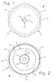
Figures 1 and 2 are schematic plan views, from above and from beneath respectively, of a cap according to the invention; -
Figures 3 and 4 are exploded schematic views, taken at different angles, of the cap ofFigures 1 and 2 ; -
Figure 5 is a schematic perspective view, in partial cross section, of the cap ofFigures 1-4 ; and -
Figure 6 is a simplified block diagram of a circuit arrangement that equips the cap ofFigures 1-5 . - In the figures, the
reference number 1 designates as a whole a cap according to the present invention, designed to occlude the filler of a fuel tank of a motor vehicle, such as, for example, a lorry or a bus. Thecap 1 comprises a first, gripping, portion, which in use is positioned on the outside of the filler of the fuel tank, and a second, locking, portion, designed to couple with the aforesaid filler. - With reference to
Figures 3-5 , the aforesaid gripping portion comprises a main body, designated by 3, which has a substantially cylindrical shape, with abottom wall 3a and aperipheral wall 3b on which gripping projections 3c are formed. At the upper end of thebody 3, thewall 3a and an end part of thewall 3b delimit aseat 3d, for housing anelectronic circuit 4, such as a printed circuit, comprising a plurality of electrical/electronic components. As may be noted, thecircuit 4 has a substantially annular configuration, corresponding to that of theseat 3d. From the bottom of theseat 3d there riseprojections 3e for positioning thecircuit 4, which is purposely provided with respective seats or throughholes 4a. Theprojections 3e are moreover exploited for fixing or positioning of alid 5 for closing in a sealed way theseat 3d, which completes the aforesaid first part of thecap 1. Thebody 3 and thelid 5 are, for example, made of moulded thermoplastic material. The seal can be guaranteed by means of the interposition of at least one gasket (not represented) set between thelid 5 and thebody 3, which are, for example, engaged or screwed together, or else by welding or gluing of thelid 5 on thebody 3, or with any other known technique suitable for the purpose. - Defined in the central region of the
body 3 is a generally tubular portion, the upper part 6a of which projects within theseat 3d. The top end of the part 6a is designed to engage a central throughhole 5a of thelid 5. Thelower part 6b of the aforesaid tubular portion projects, instead, within alower cavity 3f of thebody 3, which is also delimited by thewall 3a and by a respective portion of thewall 3b. - In the non-limiting example illustrated, the
lower part 6b of the aforesaid tubular portion is surrounded by a generally cylindrical hollow formation 3g of thebody 3, which is located within an area of thecavity 3f circumscribed by awall 3h, the latter rising from thewall 3a and being concentric to thewall 3b. - Once again with reference to
Figures 3-5 , the aforesaid locking portion of thecap 1 comprises, in the example provided, anintermediate body 8 and anend body 9, set between which is anannular gasket 7, made, for example, of elastomeric material. - The
intermediate body 8, made, for example, of moulded thermoplastic material, has acircular base 8a, projecting from the lower part of which is an axially hollowcylindrical portion 8b, which has a seat or an internal axial groove, designated by 8c inFigure 4 , which is designed to receive an engaging projection of a key-locking mechanism or device. - The
end body 9, which is preferably made of metal material, is designed to be mechanically coupled to thecylindrical portion 8b, in a known way. As may be noted, thebody 9 has a generally annular configuration and defines on the respective peripheral wall two radial appendages 9a. Saidappendages 9a provide engagement means, which are designed to co-operate with respective engagement means provided in the filler of the fuel tank, in order to constitute therewith a substantially bayonet-type coupling system. It is to be noted that in another embodiment of the invention, theappendages 9a can be replaced by a threaded attachment or an attachment of some other suitable type. The central part of thebody 9, designated by 9b, is substantially tubular and configured for being rendered fixed, in a known way, with respect to theportion 8b of theintermediate body 8, for example, by means of internal projections 9c, which engage in respective seats made on theportion 8b, not represented inFigure 3 (but one of which is partially visible inFigure 5 ). In a possible embodiment, the aforesaid seats on theportion 8b are shaped like axial grooves, in order to enable a certain degree of freedom in the axial direction for thebody 9 to allow for any possible compensation of tolerances, but are such as to constrain it in its rotary movement, i.e., in the direction of opening and closing of the cap. - The locking portion of the
cap 1 can possibly comprise a terminal, fixed to the end of thecylindrical portion 8b of thebody 8, with a spring set between said terminal and thebody 9, so as to force the latter, together with thebody 8, in the direction of thebody 3. - Designated as a whole by 10 is the key-locking device already referred to above, which is of a general conception in itself known in the sector, and hence is illustrated only schematically and described briefly as regards a possible embodiment thereof.
- The
device 10 can be of the type having a first component, designated by 10a, projecting from which in a radial direction are movable pins (not represented), which can be operated with a respective key. In the component 10a a seat 10c for the key is provided for said purpose. The component 10a is coupled so that it can turn freely on a second component 10b of thedevice 10. As emerges fromFigure 5 , the cavity of the tubular portion 6a-6b has a restriction, defining a contrast surface for a top flange part of the component 10a, whilst the component 10b is constrained to theintermediate body 8, within the cavity of the correspondingtubular portion 8b. By means of the components 10a-10b, therefore, thebodies device 10 can also be without a component rendered fixed with respect to thepart 8, for example, in the case where - as mentioned above - the locking portion of the cap comprises a terminal, fixed to the end of thecylindrical portion 8b of thebody 8, with a spring set between said terminal and thebody 9. - In their projecting condition, the aforesaid pins mechanically engage the component 10a to the
main body 3. When the key is inserted in thelocking device 10, it causes displacement of the aforesaid pins towards the inside of the component 10a. The component 10a hence becomes rotatable in thebody 3, but without being able to perform complete rotations (for example, only up to approximately 350°). For this purpose appropriate projections and detents are made in the component 10a and in thebody 3, in accordance with a technique being in itself known in the field. Once again according to a technique in itself known, the component 10a is provided with a cam profile, which, in the relative rotation between the component 10a and thebody 3, radially displaces a further movable component of thelocking device 10, which couples (or not, according to the movement imparted by the key) with theseat 8c of theintermediate body 8. In practice, then, in the opening condition of thelocking device 10, thebodies locking device 10, the further component is not coupled to theseat 8c, with thebody 3 that can hence rotate, but without transferring its own movement to thebody 8. - In general terms, therefore, the
device 10 is configured in such a way that, in the respective closing condition, any manual rotation imparted on thebody 3 cannot be transferred to thebody 8. Theradial appendages 9a of thebody 9 consequently cannot be uncoupled from the part of the bayonet-coupling system formed in the mouth of the fuel tank, thus rendering removal of thecap 1 impossible. Instead, in the opening condition of thedevice 10, a possible manual rotation imparted on thebody 3 can be transferred to thebody 8, with theradial appendages 9a of thebody 9 that can be disengaged from the part of the bayonet-coupling system formed in the mouth of the fuel tank, thus enabling removal of thecap 1. As has been said, moreover, the general configuration of thedevice 10 is such that at least the component 10a is free to turn with thebody 3, and switching of the device between the conditions of closing and opening can be obtained only by moving said component 10a angularly with respect to thebody 3, between a first predefined position and a second predefined position. Said angular movement can be obtained only by inserting the key in the component 10a, the above according a technique known in itself. - According to the main aspect of the invention, the
cap 1 is provided with means for detecting the aforesaid relative angular movement between thebody 3 and the component 10a of thelocking device 10. - In the example illustrated, the detection means comprise an excitation element, carried by the component 10a, and a sensor, which can be excited by means of the aforesaid excitation element, carried by the
body 3. More particularly, the excitation element is represented by a body made of magnetic material, designated in the figures by 11, which is positioned in arespective seat 12 formed in the component 10a of thelocking device 10. On the other side, the detector is constituted by a magnetic sensor, designated by 13, of a type in itself known, such as, for example, a Hall-effect sensor or a reed sensor, belonging to thecircuit 4. - As may be seen in
Figure 5 , thesensor 13 is mounted in a position at a side of the component 10a. For this purpose, thesensor 13 projects from the printedcircuit 4, within arespective housing 14, formed in thewall 3a of thebody 3, substantially aligned with the area of possible displacement of the magnetic element 11, in the course of the angular movement of the component 10a. In the relative angular position between the component 10a and thebody 3 that corresponds to the closing condition of thedevice 10, the magnetic element 11 is set at a distance from thesensor 13 such that the latter is not excited. Instead, following upon passage of the component 10a into the angular position with respect to thebody 3 that corresponds to the opening condition of thedevice 10, the magnetic element 11 is set facing thesensor 13, so as to be able to excite it. Evidently, the configuration can be reversed or in any case be different, for example, with the magnetic element 11 facing thesensor 13 in the closing condition of thedevice 10. In addition, thesensor 13 could have a configuration different from the one exemplified, for example, suitable for surface mounting (SMD), without having to project significantly from the printedcircuit 4, or without the need for a purposely providedhousing 14. For this purpose, the element 11 could be mounted and/or oriented in the most appropriate way, for example in an axial direction instead of in a radial direction with respect to thesensor 13. - The
electronic circuit 4, schematically represented in the block diagram ofFigure 6 , comprises a control unit CU, preferably with microcontroller or ASIC based, operatively connected to thesensor 13. The unit CU is programmed or configured for generating, according to detections made by means of thesensor 13, information or signals, which are, for example encoded ones, which represent the movement of the component 10a with respect to thebody 3; i.e., they indicate opening or closing of thelocking device 10. - In a possible embodiment, the
electronic circuit 4 comprises a data transceiver operating in wireless mode, in particular in RF mode, of a conception in itself known, which is designated by RT1 and is provided for communicating with an external electronic device RD. Transmission of the information can be governed by the control unit CU, for example following upon a change of state of thesensor 13, or else following upon a request received from the outside, for example from the electronic device RD. The electronic device RD can be of a dedicated type and installed on board the vehicle. - Preferably associated to the
circuit 4 is a suitable autonomous supply source, represented by one or more batteries DC, for example, of the button type, or else the battery of the vehicle. - In normal use, if the
body 3 of thecap 1 is rotated when thelocking device 10 is in the respective closing condition, the component 10a turns together with thepart 3, and hence thesensor 13 does not make any detection. When, instead, thedevice 10 is switched into the opening condition with the corresponding key, the component 10a moves angularly with respect to thebody 3. Said angular movement is detected by thesensor 13, which generates a signal received by the control unit CU. The change of state of thesensor 13 is communicated by the control unit CU, through the transmission means RT1, to the external electronic device RD, which is provided with a data-communication interface RT2 compatible with the transceiver RT1 of thecircuit 4. - The
circuit 4 transmits to the device RD the information of opening (and possibly closing) of thecap 1, for example, upon change of state of thesensor 13, or else periodically, for example with a frequency of a few seconds. Alternatively, the device RD sends, by means of the corresponding interface RT2, a query command to thecircuit 4, by means of the interface RT1 thereof; the query command can be sent periodically, for example with a frequency of a few seconds. The control unit CU receives, by means of the respective transceiver RT1, the query command and consequently transmits the information on the state of the sensor 13 (cap open or cap closed) to the device RD, through which the corresponding information can be made explicit or processed and retained in a memory. - In a possible embodiment, the communication interface, i.e., the transceivers RT1 and RT2, can be of a telephone type, such as modems of a cellphone type, and the data transmitted can be in the form of short messages, for example, of the SMS or MMS type.
- From the foregoing description, the characteristics of the present invention emerge clearly, as likewise its advantages, which are mainly represented by the possibility of preventing any false alarms of opening of the cap of the fuel tank of a vehicle, which are typical of detection systems of a known type. The proposed solution proves constructionally simple and presents a cost that is comparable to that of known solutions.
- Of course, without prejudice to the principle of the invention, the details of construction and the embodiments may vary widely with respect to what is described and illustrated herein purely by way of example, without thereby departing from the sphere of protection as defined in the ensuing claims.
- It is pointed out, for example, that the type of the means for detecting the angular movement of the component 10a of the
locking device 10 could be different from the one exemplified. For example, the detection system could be of an optical type, or else based upon sliding contacts, with modalities of implementation that will appear clear to any person skilled in the field. - The element for exciting the sensor need not be mounted directly in the key-locking
device 10, but can be assembled or form part of a further element, which is in turn associated to or mounted on thedevice 10. Such an additional element could be a plastic ring with a magnet 11, or else a magnetic element having an annular shape, or again an element made of plastoferrite, for example, moulded directly on the movable component of the locking device, etc. - Also the general structure of the cap and of its key-locking mechanism may be different from what is illustrated herein purely by way of example, without thereby departing from the characteristics specified in the ensuing
Claim 1. It is pointed out, in particular, that the locking or clamping portion of the cap can be of type equipped with threaded means, which are able to engage with an internal screw made in the filler of the fuel tank.
Claims (12)
- A removable cap for vehicles, of the type designed to occlude a filler of a fuel tank, the cap (1) comprising:- a first part (3, 5), having gripping means (3c);- a second part (8-10), having first coupling means (9, 9a), designed to co-operate in a selective way with second coupling means provided at the filler;- a locking device (10), switchable between a closing condition and an opening condition by means of a respective key, the device (10) being operatively set between the first part (3, 5) and the second part (8-10) and being arranged such that:the removable cap (1) being characterized in that it further comprises a circuit arrangement (4) including sensor means (11, 13) configured for detecting relative angular movement between said at least one component (10a) of the locking device (10) and the first part (3, 5) of the cap (1).- in the closing condition, a rotation movement imparted manually upon the first part (3, 5) does not enable disengagement of the first coupling means (9, 9a) from the second coupling means;- in the opening condition, a rotation movement imparted manually upon the first part (3, 5) enables disengagement of the first coupling means (9, 9a) from the second coupling means,- at least in the closing condition, at least one component (10a) of the locking device (10) is rotatable together with the first part (3, 5), switching with the key of the locking device (10) between the conditions of closing and opening causing an angular movement of said at least one component (10a) with respect to the first part (3, 5), between a first pre-defined angular position and a second pre-defined angular position;
- The cap according to Claim 1, wherein the circuit arrangement (4) further comprises a control unit (CU) arranged for generating, according to detections made by the sensor means (11, 13), encoded information or data.
- The cap according to Claim 1 and/or Claim 2, wherein the sensor means (11, 13) comprise an excitation element (11), which is rotatable together with said at least one component (10a), and a detector (13) designed to be excited by the excitation element (11).
- The cap according to Claim 3, wherein the excitation element (11) is made of magnetic material and the detector is a magnetic sensor (13), particularly a Hall-effect sensor or a reed sensor.
- The cap according to Claim 1, wherein the circuit arrangement (4) further comprises communication means (RT1), for transmission of information regarding the state of the sensor means (13).
- The cap according to Claim 5, wherein the communication means comprise a circuit (TR1) for the transmission and reception of data in a wireless mode, particularly a radiofrequency mode.
- The cap according to at least one of the preceding claims, further comprising a supply source (DC) for the circuit arrangement (4), in particular a battery.
- The cap according to Claim 1, wherein the locking device (10) is arranged such that:- in the closing condition, a rotation movement imparted manually upon the first part (3, 5) is not transferred to the second part (8-10); and- in the opening condition, a rotation movement rotation imparted manually upon the first part (3, 5) is transferred to the second part (8-10).
- The cap according to at least one of the preceding claims, wherein the circuit arrangement (4) comprises a printed circuit having a substantially annular or at least in part arched or curved shape.
- The cap according to Claims 2, 3, 5 and 7, wherein the control unit (CU), the detector (13), the communication means (RT1), and the supply source (DC) are housed in the cap itself.
- The cap according to at least one of the preceding claims, wherein the first part (3, 5) has a seat or cavity (3d) for housing the circuit arrangement (4) or a printed circuit belonging to said circuit arrangement.
- The cap according to at least one of the preceding claims, wherein the sensor means are of an optical type or else of an electrical-contact type.
Applications Claiming Priority (1)
| Application Number | Priority Date | Filing Date | Title |
|---|---|---|---|
| IT000102A ITTO20070102A1 (en) | 2007-02-09 | 2007-02-09 | DETECTION DEVICE FOR VEHICLES |
Publications (3)
| Publication Number | Publication Date |
|---|---|
| EP1961629A2 true EP1961629A2 (en) | 2008-08-27 |
| EP1961629A3 EP1961629A3 (en) | 2011-05-04 |
| EP1961629B1 EP1961629B1 (en) | 2013-01-23 |
Family
ID=39600669
Family Applications (1)
| Application Number | Title | Priority Date | Filing Date |
|---|---|---|---|
| EP20080151220 Active EP1961629B1 (en) | 2007-02-09 | 2008-02-08 | Detection device for vehicles |
Country Status (6)
| Country | Link |
|---|---|
| US (1) | US7688201B2 (en) |
| EP (1) | EP1961629B1 (en) |
| CA (1) | CA2620489C (en) |
| ES (1) | ES2402679T3 (en) |
| IT (1) | ITTO20070102A1 (en) |
| RS (1) | RS52635B (en) |
Cited By (3)
| Publication number | Priority date | Publication date | Assignee | Title |
|---|---|---|---|---|
| DE102008053777A1 (en) * | 2008-10-23 | 2010-04-29 | Dom Sicherheitstechnik Gmbh & Co Kg | Tank closure arrangement for use in tank monitor system, of e.g. bus, has safety device integrated into arrangement, where safety device cooperates with locking device and controls authorization datum of portable identification element |
| CN104161484A (en) * | 2013-05-17 | 2014-11-26 | 天佑电器(苏州)有限公司 | Filter device and dust collector using same |
| DE102017217576A1 (en) * | 2017-10-04 | 2019-04-04 | Volkswagen Aktiengesellschaft | Closure element for closing an opening of a fuel tank for a motor vehicle |
Families Citing this family (7)
| Publication number | Priority date | Publication date | Assignee | Title |
|---|---|---|---|---|
| DE102010008206A1 (en) | 2010-02-17 | 2011-08-18 | Daimler AG, 70327 | Tank device for a fuel tank of a fuel cell vehicle and tank system |
| GB2505866A (en) * | 2012-07-06 | 2014-03-19 | David John Stuart | Alarm apparatus including vehicle fuel cap and sensor |
| US20150352947A1 (en) * | 2014-06-04 | 2015-12-10 | Purple Services, Inc. | Device and system for automotive refueling |
| CN104149739B (en) * | 2014-08-08 | 2016-06-01 | 孙宗远 | A method for preventing theft of vehicle oil |
| US10147285B2 (en) * | 2016-08-15 | 2018-12-04 | Enevo Oy | Plug, system and method for detecting tampering of container |
| CN112027342B (en) * | 2020-08-25 | 2022-02-18 | 上海亲启科技有限公司 | Intelligent anti-counterfeiting device and anti-counterfeiting method for Internet of things |
| CN112606679A (en) * | 2020-12-21 | 2021-04-06 | 奇瑞汽车股份有限公司 | Take switching prompt facility's oil filler hole box hinge assembly |
Citations (1)
| Publication number | Priority date | Publication date | Assignee | Title |
|---|---|---|---|---|
| GB2343283A (en) | 1998-10-28 | 2000-05-03 | Robert William Wilkinson | A fuel tank alarm system |
Family Cites Families (5)
| Publication number | Priority date | Publication date | Assignee | Title |
|---|---|---|---|---|
| US2084045A (en) * | 1936-02-24 | 1937-06-15 | Olsen Elling | Lock means for gasoline tank caps |
| US4000632A (en) * | 1975-08-04 | 1977-01-04 | Stant Manufacturing Company, Inc. | Locking gas cap |
| US4342208A (en) * | 1976-10-29 | 1982-08-03 | Stant Inc. | Locking gas cap with torque override feature |
| US4754627A (en) * | 1987-06-22 | 1988-07-05 | Butler Iii Charles A | Closure for a vehicle gasoline filler tube |
| JP2006168517A (en) * | 2004-12-15 | 2006-06-29 | Hokuriku Electric Ind Co Ltd | Fuel tank cap and alarm device preventing cap from being left unfastened |
-
2007
- 2007-02-09 IT IT000102A patent/ITTO20070102A1/en unknown
-
2008
- 2008-02-08 RS RSP20130058 patent/RS52635B/en unknown
- 2008-02-08 ES ES08151220T patent/ES2402679T3/en active Active
- 2008-02-08 CA CA 2620489 patent/CA2620489C/en not_active Expired - Fee Related
- 2008-02-08 US US12/028,544 patent/US7688201B2/en active Active
- 2008-02-08 EP EP20080151220 patent/EP1961629B1/en active Active
Patent Citations (1)
| Publication number | Priority date | Publication date | Assignee | Title |
|---|---|---|---|---|
| GB2343283A (en) | 1998-10-28 | 2000-05-03 | Robert William Wilkinson | A fuel tank alarm system |
Cited By (4)
| Publication number | Priority date | Publication date | Assignee | Title |
|---|---|---|---|---|
| DE102008053777A1 (en) * | 2008-10-23 | 2010-04-29 | Dom Sicherheitstechnik Gmbh & Co Kg | Tank closure arrangement for use in tank monitor system, of e.g. bus, has safety device integrated into arrangement, where safety device cooperates with locking device and controls authorization datum of portable identification element |
| CN104161484A (en) * | 2013-05-17 | 2014-11-26 | 天佑电器(苏州)有限公司 | Filter device and dust collector using same |
| CN104161484B (en) * | 2013-05-17 | 2017-10-10 | 天佑电器(苏州)有限公司 | Filter and the dust catcher using the filter |
| DE102017217576A1 (en) * | 2017-10-04 | 2019-04-04 | Volkswagen Aktiengesellschaft | Closure element for closing an opening of a fuel tank for a motor vehicle |
Also Published As
| Publication number | Publication date |
|---|---|
| CA2620489A1 (en) | 2008-08-09 |
| CA2620489C (en) | 2013-09-10 |
| RS52635B (en) | 2013-06-28 |
| EP1961629B1 (en) | 2013-01-23 |
| ES2402679T3 (en) | 2013-05-07 |
| US7688201B2 (en) | 2010-03-30 |
| US20080190926A1 (en) | 2008-08-14 |
| ITTO20070102A1 (en) | 2008-08-10 |
| EP1961629A3 (en) | 2011-05-04 |
Similar Documents
| Publication | Publication Date | Title |
|---|---|---|
| EP1961629B1 (en) | Detection device for vehicles | |
| US8653390B2 (en) | Engine start/stop switch for a vehicle | |
| US5727405A (en) | Alarm padlock | |
| EP1920965B1 (en) | Monitoring apparatus for tanks and the like | |
| CN104512324B (en) | For staying the system for prompting of article in the car | |
| RU2052360C1 (en) | Device to prevent unauthorized use of automobile and lock for gearshift lever | |
| US10940984B2 (en) | Battery powered keyless locking cap | |
| US20120192602A1 (en) | Touch pad lock assembly | |
| US8674832B1 (en) | Wireless bolt lock remote | |
| EP3137347A1 (en) | Vehicular keyless entry system | |
| JP2012087555A (en) | Door lock device | |
| US20150137975A1 (en) | Alarmed theft-preventing device | |
| CN101093614A (en) | Vehicle control system | |
| JP2004209999A (en) | Vehicle anti-theft device and vehicle control method | |
| WO2011013113A1 (en) | A vehicle safety apparatus | |
| US7064651B2 (en) | Automatic vehicle theft prevention system | |
| JP2008207795A (en) | Vehicle anti-theft device | |
| US20180154864A1 (en) | Vehicle remote control system | |
| CN201245132Y (en) | Oil tank lid with alarming function | |
| US20070126577A1 (en) | Door latch position sensor | |
| JP5307449B2 (en) | Electric lock device | |
| EP2576263B1 (en) | A tank closing unit | |
| GB2505866A (en) | Alarm apparatus including vehicle fuel cap and sensor | |
| JP2006062401A (en) | Security device for vehicle of after-installation type | |
| CN207931848U (en) | Anti-theft electric motor car |
Legal Events
| Date | Code | Title | Description |
|---|---|---|---|
| PUAI | Public reference made under article 153(3) epc to a published international application that has entered the european phase |
Free format text: ORIGINAL CODE: 0009012 |
|
| AK | Designated contracting states |
Kind code of ref document: A2 Designated state(s): AT BE BG CH CY CZ DE DK EE ES FI FR GB GR HR HU IE IS IT LI LT LU LV MC MT NL NO PL PT RO SE SI SK TR |
|
| AX | Request for extension of the european patent |
Extension state: AL BA MK RS |
|
| PUAL | Search report despatched |
Free format text: ORIGINAL CODE: 0009013 |
|
| AK | Designated contracting states |
Kind code of ref document: A3 Designated state(s): AT BE BG CH CY CZ DE DK EE ES FI FR GB GR HR HU IE IS IT LI LT LU LV MC MT NL NO PL PT RO SE SI SK TR |
|
| AX | Request for extension of the european patent |
Extension state: AL BA MK RS |
|
| RIC1 | Information provided on ipc code assigned before grant |
Ipc: B60R 25/10 20060101ALI20110328BHEP Ipc: B60K 15/04 20060101AFI20110328BHEP |
|
| REG | Reference to a national code |
Ref country code: DE Ref legal event code: R079 Ref document number: 602008021819 Country of ref document: DE Free format text: PREVIOUS MAIN CLASS: B60R0025100000 Ipc: B60K0015040000 |
|
| GRAP | Despatch of communication of intention to grant a patent |
Free format text: ORIGINAL CODE: EPIDOSNIGR1 |
|
| 17P | Request for examination filed |
Effective date: 20111103 |
|
| RIC1 | Information provided on ipc code assigned before grant |
Ipc: B60R 25/10 20060101ALI20111122BHEP Ipc: B60K 15/04 20060101AFI20111122BHEP Ipc: G01R 33/07 20060101ALI20111122BHEP |
|
| AKX | Designation fees paid |
Designated state(s): AT BE BG CH CY CZ DE DK EE ES FI FR GB GR HR HU IE IS IT LI LT LU LV MC MT NL NO PL PT RO SE SI SK TR |
|
| AXX | Extension fees paid |
Extension state: RS Payment date: 20111103 |
|
| GRAS | Grant fee paid |
Free format text: ORIGINAL CODE: EPIDOSNIGR3 |
|
| GRAA | (expected) grant |
Free format text: ORIGINAL CODE: 0009210 |
|
| AK | Designated contracting states |
Kind code of ref document: B1 Designated state(s): AT BE BG CH CY CZ DE DK EE ES FI FR GB GR HR HU IE IS IT LI LT LU LV MC MT NL NO PL PT RO SE SI SK TR |
|
| AX | Request for extension of the european patent |
Extension state: RS |
|
| REG | Reference to a national code |
Ref country code: GB Ref legal event code: FG4D |
|
| REG | Reference to a national code |
Ref country code: CH Ref legal event code: EP |
|
| REG | Reference to a national code |
Ref country code: AT Ref legal event code: REF Ref document number: 594761 Country of ref document: AT Kind code of ref document: T Effective date: 20130215 Ref country code: CH Ref legal event code: EP |
|
| REG | Reference to a national code |
Ref country code: IE Ref legal event code: FG4D |
|
| REG | Reference to a national code |
Ref country code: SE Ref legal event code: TRGR |
|
| REG | Reference to a national code |
Ref country code: DE Ref legal event code: R096 Ref document number: 602008021819 Country of ref document: DE Effective date: 20130321 |
|
| REG | Reference to a national code |
Ref country code: ES Ref legal event code: FG2A Ref document number: 2402679 Country of ref document: ES Kind code of ref document: T3 Effective date: 20130507 |
|
| REG | Reference to a national code |
Ref country code: AT Ref legal event code: MK05 Ref document number: 594761 Country of ref document: AT Kind code of ref document: T Effective date: 20130123 |
|
| REG | Reference to a national code |
Ref country code: LT Ref legal event code: MG4D |
|
| REG | Reference to a national code |
Ref country code: NL Ref legal event code: VDEP Effective date: 20130123 |
|
| PG25 | Lapsed in a contracting state [announced via postgrant information from national office to epo] |
Ref country code: NO Free format text: LAPSE BECAUSE OF FAILURE TO SUBMIT A TRANSLATION OF THE DESCRIPTION OR TO PAY THE FEE WITHIN THE PRESCRIBED TIME-LIMIT Effective date: 20130423 Ref country code: BG Free format text: LAPSE BECAUSE OF FAILURE TO SUBMIT A TRANSLATION OF THE DESCRIPTION OR TO PAY THE FEE WITHIN THE PRESCRIBED TIME-LIMIT Effective date: 20130423 Ref country code: LT Free format text: LAPSE BECAUSE OF FAILURE TO SUBMIT A TRANSLATION OF THE DESCRIPTION OR TO PAY THE FEE WITHIN THE PRESCRIBED TIME-LIMIT Effective date: 20130123 Ref country code: CY Free format text: LAPSE BECAUSE OF FAILURE TO SUBMIT A TRANSLATION OF THE DESCRIPTION OR TO PAY THE FEE WITHIN THE PRESCRIBED TIME-LIMIT Effective date: 20130123 Ref country code: AT Free format text: LAPSE BECAUSE OF FAILURE TO SUBMIT A TRANSLATION OF THE DESCRIPTION OR TO PAY THE FEE WITHIN THE PRESCRIBED TIME-LIMIT Effective date: 20130123 Ref country code: BE Free format text: LAPSE BECAUSE OF FAILURE TO SUBMIT A TRANSLATION OF THE DESCRIPTION OR TO PAY THE FEE WITHIN THE PRESCRIBED TIME-LIMIT Effective date: 20130123 Ref country code: IS Free format text: LAPSE BECAUSE OF FAILURE TO SUBMIT A TRANSLATION OF THE DESCRIPTION OR TO PAY THE FEE WITHIN THE PRESCRIBED TIME-LIMIT Effective date: 20130523 |
|
| PG25 | Lapsed in a contracting state [announced via postgrant information from national office to epo] |
Ref country code: SI Free format text: LAPSE BECAUSE OF FAILURE TO SUBMIT A TRANSLATION OF THE DESCRIPTION OR TO PAY THE FEE WITHIN THE PRESCRIBED TIME-LIMIT Effective date: 20130123 Ref country code: LV Free format text: LAPSE BECAUSE OF FAILURE TO SUBMIT A TRANSLATION OF THE DESCRIPTION OR TO PAY THE FEE WITHIN THE PRESCRIBED TIME-LIMIT Effective date: 20130123 Ref country code: PT Free format text: LAPSE BECAUSE OF FAILURE TO SUBMIT A TRANSLATION OF THE DESCRIPTION OR TO PAY THE FEE WITHIN THE PRESCRIBED TIME-LIMIT Effective date: 20130523 Ref country code: PL Free format text: LAPSE BECAUSE OF FAILURE TO SUBMIT A TRANSLATION OF THE DESCRIPTION OR TO PAY THE FEE WITHIN THE PRESCRIBED TIME-LIMIT Effective date: 20130123 Ref country code: NL Free format text: LAPSE BECAUSE OF FAILURE TO SUBMIT A TRANSLATION OF THE DESCRIPTION OR TO PAY THE FEE WITHIN THE PRESCRIBED TIME-LIMIT Effective date: 20130123 Ref country code: FI Free format text: LAPSE BECAUSE OF FAILURE TO SUBMIT A TRANSLATION OF THE DESCRIPTION OR TO PAY THE FEE WITHIN THE PRESCRIBED TIME-LIMIT Effective date: 20130123 Ref country code: GR Free format text: LAPSE BECAUSE OF FAILURE TO SUBMIT A TRANSLATION OF THE DESCRIPTION OR TO PAY THE FEE WITHIN THE PRESCRIBED TIME-LIMIT Effective date: 20130424 |
|
| PG25 | Lapsed in a contracting state [announced via postgrant information from national office to epo] |
Ref country code: HR Free format text: LAPSE BECAUSE OF FAILURE TO SUBMIT A TRANSLATION OF THE DESCRIPTION OR TO PAY THE FEE WITHIN THE PRESCRIBED TIME-LIMIT Effective date: 20130123 Ref country code: MC Free format text: LAPSE BECAUSE OF NON-PAYMENT OF DUE FEES Effective date: 20130228 |
|
| REG | Reference to a national code |
Ref country code: CH Ref legal event code: PL |
|
| PG25 | Lapsed in a contracting state [announced via postgrant information from national office to epo] |
Ref country code: SK Free format text: LAPSE BECAUSE OF FAILURE TO SUBMIT A TRANSLATION OF THE DESCRIPTION OR TO PAY THE FEE WITHIN THE PRESCRIBED TIME-LIMIT Effective date: 20130123 Ref country code: CH Free format text: LAPSE BECAUSE OF NON-PAYMENT OF DUE FEES Effective date: 20130228 Ref country code: LI Free format text: LAPSE BECAUSE OF NON-PAYMENT OF DUE FEES Effective date: 20130228 Ref country code: DK Free format text: LAPSE BECAUSE OF FAILURE TO SUBMIT A TRANSLATION OF THE DESCRIPTION OR TO PAY THE FEE WITHIN THE PRESCRIBED TIME-LIMIT Effective date: 20130123 Ref country code: EE Free format text: LAPSE BECAUSE OF FAILURE TO SUBMIT A TRANSLATION OF THE DESCRIPTION OR TO PAY THE FEE WITHIN THE PRESCRIBED TIME-LIMIT Effective date: 20130123 Ref country code: RO Free format text: LAPSE BECAUSE OF FAILURE TO SUBMIT A TRANSLATION OF THE DESCRIPTION OR TO PAY THE FEE WITHIN THE PRESCRIBED TIME-LIMIT Effective date: 20130123 Ref country code: CZ Free format text: LAPSE BECAUSE OF FAILURE TO SUBMIT A TRANSLATION OF THE DESCRIPTION OR TO PAY THE FEE WITHIN THE PRESCRIBED TIME-LIMIT Effective date: 20130123 |
|
| PLBE | No opposition filed within time limit |
Free format text: ORIGINAL CODE: 0009261 |
|
| STAA | Information on the status of an ep patent application or granted ep patent |
Free format text: STATUS: NO OPPOSITION FILED WITHIN TIME LIMIT |
|
| REG | Reference to a national code |
Ref country code: IE Ref legal event code: MM4A |
|
| GBPC | Gb: european patent ceased through non-payment of renewal fee |
Effective date: 20130423 |
|
| 26N | No opposition filed |
Effective date: 20131024 |
|
| PG25 | Lapsed in a contracting state [announced via postgrant information from national office to epo] |
Ref country code: GB Free format text: LAPSE BECAUSE OF NON-PAYMENT OF DUE FEES Effective date: 20130423 Ref country code: IE Free format text: LAPSE BECAUSE OF NON-PAYMENT OF DUE FEES Effective date: 20130208 |
|
| REG | Reference to a national code |
Ref country code: DE Ref legal event code: R097 Ref document number: 602008021819 Country of ref document: DE Effective date: 20131024 |
|
| PG25 | Lapsed in a contracting state [announced via postgrant information from national office to epo] |
Ref country code: MT Free format text: LAPSE BECAUSE OF FAILURE TO SUBMIT A TRANSLATION OF THE DESCRIPTION OR TO PAY THE FEE WITHIN THE PRESCRIBED TIME-LIMIT Effective date: 20130123 |
|
| PG25 | Lapsed in a contracting state [announced via postgrant information from national office to epo] |
Ref country code: TR Free format text: LAPSE BECAUSE OF FAILURE TO SUBMIT A TRANSLATION OF THE DESCRIPTION OR TO PAY THE FEE WITHIN THE PRESCRIBED TIME-LIMIT Effective date: 20130123 |
|
| PG25 | Lapsed in a contracting state [announced via postgrant information from national office to epo] |
Ref country code: LU Free format text: LAPSE BECAUSE OF NON-PAYMENT OF DUE FEES Effective date: 20130208 Ref country code: HU Free format text: LAPSE BECAUSE OF FAILURE TO SUBMIT A TRANSLATION OF THE DESCRIPTION OR TO PAY THE FEE WITHIN THE PRESCRIBED TIME-LIMIT; INVALID AB INITIO Effective date: 20080208 |
|
| REG | Reference to a national code |
Ref country code: FR Ref legal event code: PLFP Year of fee payment: 9 |
|
| REG | Reference to a national code |
Ref country code: FR Ref legal event code: PLFP Year of fee payment: 10 |
|
| REG | Reference to a national code |
Ref country code: FR Ref legal event code: PLFP Year of fee payment: 11 |
|
| PGFP | Annual fee paid to national office [announced via postgrant information from national office to epo] |
Ref country code: DE Payment date: 20220225 Year of fee payment: 15 |
|
| PGFP | Annual fee paid to national office [announced via postgrant information from national office to epo] |
Ref country code: SE Payment date: 20220218 Year of fee payment: 15 Ref country code: IT Payment date: 20220210 Year of fee payment: 15 Ref country code: FR Payment date: 20220224 Year of fee payment: 15 Ref country code: ES Payment date: 20220314 Year of fee payment: 15 |
|
| REG | Reference to a national code |
Ref country code: DE Ref legal event code: R119 Ref document number: 602008021819 Country of ref document: DE |
|
| REG | Reference to a national code |
Ref country code: SE Ref legal event code: EUG |
|
| PG25 | Lapsed in a contracting state [announced via postgrant information from national office to epo] |
Ref country code: SE Free format text: LAPSE BECAUSE OF NON-PAYMENT OF DUE FEES Effective date: 20230209 |
|
| PG25 | Lapsed in a contracting state [announced via postgrant information from national office to epo] |
Ref country code: IT Free format text: LAPSE BECAUSE OF NON-PAYMENT OF DUE FEES Effective date: 20230208 Ref country code: FR Free format text: LAPSE BECAUSE OF NON-PAYMENT OF DUE FEES Effective date: 20230228 Ref country code: DE Free format text: LAPSE BECAUSE OF NON-PAYMENT OF DUE FEES Effective date: 20230901 |
|
| REG | Reference to a national code |
Ref country code: ES Ref legal event code: FD2A Effective date: 20240403 |
|
| PG25 | Lapsed in a contracting state [announced via postgrant information from national office to epo] |
Ref country code: ES Free format text: LAPSE BECAUSE OF NON-PAYMENT OF DUE FEES Effective date: 20230209 |
|
| PG25 | Lapsed in a contracting state [announced via postgrant information from national office to epo] |
Ref country code: ES Free format text: LAPSE BECAUSE OF NON-PAYMENT OF DUE FEES Effective date: 20230209 |