EP1961628A2 - Vehicle front structure - Google Patents
Vehicle front structure Download PDFInfo
- Publication number
- EP1961628A2 EP1961628A2 EP08002968A EP08002968A EP1961628A2 EP 1961628 A2 EP1961628 A2 EP 1961628A2 EP 08002968 A EP08002968 A EP 08002968A EP 08002968 A EP08002968 A EP 08002968A EP 1961628 A2 EP1961628 A2 EP 1961628A2
- Authority
- EP
- European Patent Office
- Prior art keywords
- vehicle
- cover member
- fender panel
- vehicle front
- front structure
- Prior art date
- Legal status (The legal status is an assumption and is not a legal conclusion. Google has not performed a legal analysis and makes no representation as to the accuracy of the status listed.)
- Granted
Links
Images




Classifications
-
- B—PERFORMING OPERATIONS; TRANSPORTING
- B60—VEHICLES IN GENERAL
- B60R—VEHICLES, VEHICLE FITTINGS, OR VEHICLE PARTS, NOT OTHERWISE PROVIDED FOR
- B60R21/00—Arrangements or fittings on vehicles for protecting or preventing injuries to occupants or pedestrians in case of accidents or other traffic risks
- B60R21/34—Protecting non-occupants of a vehicle, e.g. pedestrians
-
- B—PERFORMING OPERATIONS; TRANSPORTING
- B60—VEHICLES IN GENERAL
- B60R—VEHICLES, VEHICLE FITTINGS, OR VEHICLE PARTS, NOT OTHERWISE PROVIDED FOR
- B60R21/00—Arrangements or fittings on vehicles for protecting or preventing injuries to occupants or pedestrians in case of accidents or other traffic risks
- B60R21/34—Protecting non-occupants of a vehicle, e.g. pedestrians
- B60R2021/343—Protecting non-occupants of a vehicle, e.g. pedestrians using deformable body panel, bodywork or components
Definitions
- the present invention relates to vehicle front structure in which a base portion of a cover member is mounted on an inside edge of a fender panel.
- a front fender panel In a vehicle front structure, in order to improve pedestrian protection performance, there are cases in which the inside edge of a front fender panel is mounted to an apron upper member via an energy-absorbing bracket (refer to, for example, Japanese Patent Application Publication No. JP-A-2005-14763 ).
- the inside edge of the front fender panel or energy-absorbing bracket might be covered and hidden by a fender protector from the inside in the transverse direction of the vehicle, one end part of the fender protector being mounted to the end part on the inside of the fender panel and also mounted to the apron upper member.
- the shock-absorbing part may form a part of the inside end part of the fender panel.
- the cover member may be a guide means that guides the cover member toward the insertion part of the vehicle side-structure.
- the guide means may be formed with an end that is directed toward the insertion part of the vehicle side-structure.
- the cover member may have a weak part that serves as the origin point for bending deformation substantially in the transverse direction of the vehicle, formed in an intermediate part between the base end part and the distal end.
- the effect is achieved that when a load from a colliding body acts on the upper end part of the fender panel, the repulsing force from the cover member with respect to the fender panel side is effectively suppressed.
- a weak point serving as the origin point of bending deformation substantially in the transverse direction of the vehicle is provided in the intermediate part of the cover member, when a load from a colliding body acts on the upper end of the fender panel from above, even if the far end of the cover member contacts the vehicle side-structure at the time of insertion into the insertion part, the cover member is successively inserted into the insertion part as it bends slightly with the weak part as the origin.
- the cover member may have a cutaway part in the weak part. Also, in the above- described configuration the cover member may be formed by bending at the weak point, or may have thin material at the weak point. Additionally, the cover member may have one or more holes.
- a dimension L1 from the lowermost end position to the insertion opening of the insertion part and a dimension L2 from the distal end to the weak part of the cover member may be set so that the relationship L2 ⁇ L1 is satisfied.
- the dimension L1 from the lowermost end position to the insertion opening of the insertion part and the dimension L2 from the distal end to the weak part of the cover member are set so that the relationship L2 ⁇ L1 is satisfied, when a force from a colliding body acts on the upper end of the fender panel from above, the cover member is inserted until it reaches the lowermost end position of the insertion part, after which there is bending deformation with a low load at the weak part.
- the vehicle side-structure may be formed by a plurality of members, with the insertion part being formed as a gap between the plurality of members.
- the vehicle side-structure may be formed by one member, with the insertion part being formed as a channel in the member.
- the UP, FR, and IN arrows represent the vehicle upward direction, vehicle front direction, and vehicle inward direction (in the transverse direction), respectively.
- a hood 14 made of metal is disposed in the vehicle upward direction above the engine room 12 so as to be able to open the engine compartment 12.
- the hood 14 includes a hood outer panel 16 forming the outer sheet of the hood 14, and a hood inner panel 18 forming the inner sheet of the hood 14.
- the outer peripheral part of the hood outer panel 16 is joined by hemming to the hood inner panel 18.
- an outer wall part 22 of the front fender panel 20 is disposed on the side of the hood outer panel 16, that is, on the side of the vehicle front 10.
- the boundary part 26 between the hood outer panel 16 that forms the outer sheet of the hood 14 and the front fender panel 20 that forms the side of the vehicle front 10 extends substantially along the longitudinal direction of the vehicle at both end parts of the hood 14 in the transverse direction.
- the front fender panel 20 includes an outer side wall part 22 that forms a designed surface that covers the top of the front wheel 19 (refer to FIG. 1 ), and an inner wall part 24 that hangs downward and is curved substantially in the vehicle downward direction (engine compartment 12 side) from the upper end part 22A of the outer wall part 22 at the boundary part 26 with the hood outer panel 16.
- the inner wall part 24 as the inner end part of the front fender panel 20 has an inner vertical wall part 24A hanging downward in substantially the vehicle downward direction from the upper end part 22A of the outer wall part 22, and a horizontal flange part 24B extending outward substantially horizontally toward the engine compartment 12 side from the lower end part of the inner vertical wall part 24A.
- the distal end part of the horizontal flange part 24B that is, the inner end part 24C of the front fender panel 20, is formed to have a semicircular cross-section that is convex in the vehicle upward direction.
- a sealing material 28 made of a resilient material (rubber) is disposed on the vehicle inner side of the inner vertical wall part 24A, and makes pressing contact in an elastically deformed condition with both ends of the outer peripheral part of the hood 14 in the transverse direction.
- An apron upper member 30 that forms a part of the vehicle body is disposed on the lower side of the horizontal flange part 24B of the front fender panel 20.
- the apron upper member 30 is a vehicle body framework member that is disposed with its long direction in the substantially longitudinal direction of the vehicle on the inside in the transverse direction of the outside wall 22 of the front fender panel 20, having a cross-sectional shape that is open toward the lower direction of the vehicle, and being fused onto an apron sub-assembly 32 at the lower side.
- the apron sub-assembly 32 extends in the transverse direction below the apron upper member 30 and, as shown in FIG 4 , has a protruding part 32A facing toward the upper vehicle direction at an inside position in the transverse direction.
- a horizontal flange part 24B of the front fender panel 20 and the apron upper member 30 are linked by a shock-absorbing bracket 34 as a shock-absorbing part.
- a plurality of shock-absorbing brackets 34 are disposed at a prescribed interval in substantially the longitudinal direction of the vehicle. By doing this, the horizontal flange part 24B of the front fender panel 20 is supported by the apron upper member 30 via the shock-absorbing bracket 34.
- the shock-absorbing bracket 34 is convex when viewed from the side of the vehicle, and includes a fender mounting part 36, a front and rear pair of apron side mounting parts 38, and a front and rear pair of support legs 40.
- the fender mounting part 36 fixes the horizontal flange part 24B of the front fender panel 20 and the top wall part 30B of the apron upper member 30.
- the apron mounting part 38 is placed onto the top wall part 30B of the apron upper member 30 in surface contact therewith, and fixed to the top all part 30B by spot welding or the like.
- the support legs 40 join the flat sheet fending mounting part 36 and the flat sheet apron side mounting part 38 in the top-to-bottom vehicle direction, and can be deformed in the direction of crushing with respect to the action of a load acting from the upper direction of the vehicle. That is, the shock-absorbing bracket 34 links the horizontal flange part 24B of the front fender panel 20 to the apron upper member 30 and can deform in the direction of crushing with respect to the action of a load acting from the upper direction of the vehicle.
- a bolt passage hole (not shown in the drawing) is passed through the fender mounting part 36, and additionally a weld nut 42 is fused to the rear surface thereof.
- the horizontal flange part 24B of the front fender panel 20 rests on the upper surface of the fender mounting part 36 and the bolt 44 is inserted from above the fender mounting part 36 and screwed into the weld nut 42. In this manner, the horizontal flange part 24B of the front fender panel 20 is mounted to the top wall part 30B of the apron upper member 30 via the shock-absorbing bracket 34.
- a terminal part 24C on the inside of the front fender panel 20 and a fender protector 50 as a covering member are mounting to the horizontal flange part 24B of the front fender panel 20.
- the fender protector 50 covers and hides the shock-absorbing bracket 34 from the inside in the transverse direction, and extends continuously in the substantially longitudinal direction of the vehicle.
- the fender protector 50 is mounted to the horizontal flange part 24B of the front fender panel 20 via a clip 58 made of resin, and hangs downward in the substantially downward direction of the vehicle with the distal end 56 as a free end.
- the fender protector 50 serving as a cover is formed as a single piece using a resin material, has a relatively low rigidity, and can deform elastically.
- the base end part 52 of the fender protector 50 is disposed at the above the horizontal flange part 24B of the front fender panel 20, and the upper surface 52A thereof is substantially parallel with the horizontal flange part 24B.
- the base end part 52 of the fender protector 50 has integrally formed thereon, at a prescribed position on the lower surface side thereof, a substantially square hollow mounting seat 52B.
- the mounting seat 52B has one end (the left-side part in FIG 3 ) that is open and also has side wall parts 152B and a base wall part 252B that is disposed substantially horizontally to join the lower ends of the side wall parts 152.
- the central part of the base wall part 252B in the longitudinal direction of the vehicle has formed thereon a substantially rectangular mounting cutout 352B (refer to FIG. 3 ) facing from the outside in the transverse direction toward the inside in the transverse direction.
- the clip 58 is mounted to the mounting seat 52B by an elastically deformable engaging part 58A being inserted from the mounting cutout 352B to sandwich the base wall part 252B and, with the semi-elliptical solid attachment part 58B being inserted through the clip attachment hole 124 formed in the horizontal flange part 24B, a retaining tongue 58C is supported by the peripheral part of a clip attachment hole 124B.
- a vehicle body side structure 60 that includes the apron upper member 30 and a wire harness protector 62 that is provided at a distance in the inside of the transverse direction from the vertical wall part 30A of the apron upper member 30 is disposed at the side below and the surrounding area around the distal end 56 of the fender protector 50.
- the vehicle body side structure 60 has an insertion opening 64A formed substantially along the vehicle longitudinal direction in the vicinity of the distal end 56 of the fender protector 50, and has a insertion part 64 (interpart insertion part) in the shape of an elongated channel into which the fender protector 50 can be inserted from the insertion opening 64A when a load acts on the upper end part 22A of the front fender panel 20 from the vehicle upper direction.
- the insertion part 64 is a gap formed in an interpart space formed by the vertical wall part 30A on the inside of the apron upper member 30 in the transverse direction and the vertical wall part 62A on the outside of the wire harness protector 62 in the vehicle longitudinal direction substantially along the vehicle longitudinal direction, the dimensions of the gap in the insertion part 64 being set to be larger than the sheet thickness of the fender protector 50.
- an engine cover 68 made of resin is formed to include the side substantially above the wire harness protector 62, the engine cover 68 is set at a position that does not hinder the advance of the fender protector 50 when the fender protector 50 is inserted into the insertion part 64.
- a guide part 56A is provided in the distal end 56 as a guide means that is bent toward the inside in the transverse direction.
- the guide part 56A has a shape that facilitates the sliding of the fender protector 50 into the insertion part 64.
- the end part thereof is a shape that is directed toward the insertion part 64, and when a load acts on the upper end 22A of the front fender panel 20 from the upward vehicle direction, by causing the distal end 56 to slide in the downward vehicle direction from the vicinity of the insertion opening 64A, the fender protector 50 is guided toward the insertion part 64.
- the intermediate part 54 between the base end part 52 and the distal end 56 of the fender protector 50 includes an intermediate upper part 54A that is bent in the vehicle downward direction from the end part of the base end part 52 in the transverse direction so as to extend at an inclination on the inside in the transverse direction, and an intermediate lower part 54B that is bent at a bending part 54C from the lower end part of the intermediate upper part 54A and that extends substantially in the vehicle downward direction.
- a notch 54D is formed in the bending part 54C of the intermediate part 54 of the fender protector 50, and the bending part 54C with the notch 54D formed therein is a weak part 55 that serves as the origin point for bending deformation substantially in the transverse direction.
- the dimension L1 from the lowermost end position 64B to the insertion opening 64A of the insertion part 64 and the dimension L2 from the distal end 56 to the weak part 55 of the fender protector 50 are set so that the relationship L2 ⁇ L1 is satisfied.
- the shock-absorbing bracket 34 not only links the horizontal flange part 24B of the front fender panel 20 and the apron upper member 30 at a part that is substantially in the vehicle longitudinal direction, but also can deform in the direction of crushing under the action of a load acting from the upward vehicle direction.
- the force of impact F when that occurs causes the shock-absorbing bracket 34 to deform so as to be crushed, thereby absorbing the energy at the time of the collision.
- the terminal part 24C on the inside of the front fender panel 20 and the shock-absorbing bracket 34 are covered and hidden from the inside in the transverse direction by the fender protector 50 that extends continuously in the substantially longitudinal direction of the vehicle.
- the hood 14 (refer to FIG 1 ) is opened, the terminal part 24C on the inside of the front fender panel 20 and the shock-absorbing bracket 34 cannot be visually verified from the front side of the vehicle. For this reason, appearance is good.
- the fender protector 50 is inserted from the insertion opening 64A when a collision of a colliding body 70 occurs, in which a load acts from the vehicle upward direction on the upper end part of the front fender panel 20. For this reason, when a collision occurs with the colliding body 70, as shown in FIG.
- the guide part 56A guides the fender protector 50 toward the insertion part 64 at the time of a collision with the colliding body 70, as shown in FIG 3 , even in the case, for example, in which the relative position of the distal end 56 of the fender protector 50 with respect to the insertion part 64 is offset in the assembled condition, variation in the relative position of the fender protector 50 with respect to the insertion part 64 is tolerated, and the fender protector 50 is smoothly inserted so as to slide toward the insertion part 64.
- the fender protector 50 is a resin part, some small variation in dimensions (for example, 1 mm to 2 mm) may occur, and a positional adjustment of the front fender panel 20 and the hood 14 (adjustment when placing the front fender panel 20 in place) may cause a variation in the relative position between the front fender panel 20 and the vehicle body side structure 60 (including the apron upper member 30). According to this embodiment, however, even if these cause a slight shift in the relative position of the fender protector 50 with respect to the insertion part 64 from the proper position indicated in the drawings, the guide part 56A can cause the fender protector 50 to slide into the insertion part 64.
- the weak part 55 that serves as the origin point for bending deformation toward substantially in the transverse direction is provided at the intermediate part 54 of the fender protector 50, when a collision occurs with the colliding body 70, even if the distal end 56 of the fender protector 50 comes into contact with the vehicle body side structure 60 at the stage at which the distal end 56 is inserted into the insertion part 64, the fender protector 50 is successively inserted into the insertion part 64 as it bends slightly with the weak part 55 as the origin, thereby effectively suppressing repulsive force toward the front fender panel 20.
- the dimension L1 from the lowermost end position 64B to the insertion opening 64A of the insertion part 64 and the dimension L2 from the distal end 56 to the weak part 55 of the fender protector 50 are set so that the relationship L2 ⁇ L1 is satisfied, when a collision occurs with the colliding body 70, the distal end 56 of the fender protector 50 is inserted until it reaches the lowermost end position 64B of the insertion part 64, after which, with the fender protector 50 hitting bottom at the lowermost end position 64B of the insertion part 64, there is bending deformation with a low load toward substantially the transverse direction with the weak part 55 as the origin. That is, because the bending deformation of the fender protector 50 at low load occurs after the insertable dimension of the insertion part 64 is fully used, it is possible to effectively maintain the deformation stroke amount of the front fender panel 20.
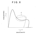
- FIG 6 which shows the relationship the displacement (S) of the fender protector and the deformation acceleration (G) (hereinafter "G-S curve"), compared to the comparison structure in which the distal end of the fender protector is fixed to the apron upper member (shown by the dotted line G-S), because there is almost no repulsing force by the deformation of the fender protector 50, the acceleration (load) in the latter half of the waveform is reduced and it is possible to obtain good acceleration (region surrounded by the single dot-dash line in FIG. 6 ), and, because there is little residual uncrushed amount, it is also possible to achieve stroke more reliably.
- G-S curve shows the relationship the displacement (S) of the fender protector and the deformation acceleration (G)
- vehicle body side structure engine cover 80
- vehicle body side structure engine cover 80
- other aspects of the configuration being substantially the same as the first embodiment.
- Constituent elements that are substantially the same as in the first embodiment are assigned the same reference numerals and the description thereof are omitted herein.
- the engine cover (built-in part) 80 as the vehicle body side structure is provided so as to extend as far as a part of the apron upper member 30 toward the inside in the transverse direction, and has an insertion opening 82A that is formed along the substantially longitudinal direction of the vehicle approaching the distal end 56 of the fender protector 50, and an insertion part 82 in the form of an elongated channel into which the fender protector 50 can slide into from the insertion opening 82A (from the insertion part 56 side). That is, the engine cover 80 can accept the fender protector 50 inside the channel-shaped insertion part 82. With this type of configuration as well, the same type of operation and effect are achieved as with the first embodiment.
- the structure is such that the fender protector 50 is slid into the insertion parts 64, 82 when a load acts on the upper end part 22A of the front fender panel 20 from above the colliding body relative to the vehicle
- a structure may be adopted in which, when the load acts, the distal end side of the covering member is inserted into the insertion part without coming into contact with the vicinity of the insertion opening or the inner wall of the insertion part.
- the shock-absorbing bracket 34 as the shock-absorbing part links the horizontal flange part 24B of the front fender panel 20 with the apron upper member 30
- a structure may be adopted in which a shock-absorbing part capable of deformation in the crushing direction with respect to a load acting from above relative to the vehicle, is fixed, for example, the terminal part side on the inside of the fender panel, is fixed to the apron upper member, the end part of the inside of the fender panel may be a vertical wall part forming a art of the end part of the inside of the fender panel.
- the distal end 56 of the fender protector 50 is provided with a guide part 56A as a guide means
- a configuration in which there is no guide means may be adopted, and a configuration may be adopted in which a different guide means such as one that guides a covering member toward the insertion part when a load acts from above relative to the vehicle on the upper end part of the fender panel is provided on a part of the vehicle body side structure.
- a configuration is preferable in which a weak part 55 is provided in the intermediate part 54 of the fender protector 50, such as shown in FIG 3
- a configuration may be adopted in which a weak part is not provided in the intermediate part of the covering member.
- the weak part 55 in the above-noted embodiments has a notch 54D formed in the bending part 54C, as long as the weak part is a part that forms the origin of bending deformation in bending in substantially the transverse direction, the weak point may be another weak point, such as simply a bending part, a part having thin material, or a formed part having a small hole.
- the dimension L1 from the lowermost end position 64B to the insertion opening 64A of the insertion part 64 and the dimension L2 from the distal end 56 to the weak part 55 of the fender protector 50 are set so that the relationship L2 ⁇ L1 is satisfied and this type of configuration is preferred, an alternate configuration may be adopted in which the dimension L2 is slightly shorter than L1, for example, so that the relationship L2 ⁇ L1 is not satisfied.
- the intermediate upper part of the covering member may extend in the downward vehicle direction at an inclination toward the outside in the transverse direction.
- the intermediate lower part 54B of the fender protector 50 extends substantially in the downward vehicle direction
- the lower part of the intermediate part of the covering member may alternatively extend in the downward vehicle direction at an inclination toward either the outside or the inside in the transverse direction.
- the inside end part of the fender panel may, for example, be bent substantially in the downward vehicle direction so that it is provided substantially horizontally, bent toward the inside in the transverse direction at the boundary part with the hood panel.
Landscapes
- Engineering & Computer Science (AREA)
- Mechanical Engineering (AREA)
- Body Structure For Vehicles (AREA)
Abstract
Description
- The present invention relates to vehicle front structure in which a base portion of a cover member is mounted on an inside edge of a fender panel.
- In a vehicle front structure, in order to improve pedestrian protection performance, there are cases in which the inside edge of a front fender panel is mounted to an apron upper member via an energy-absorbing bracket (refer to, for example, Japanese Patent Application Publication No.
JP-A-2005-14763 - In the above-described structure, however, when a body colliding with the upper end part of the fender panel acts to present a load from above the vehicle, with the fender protector generating a prescribed repulsive force, there is generally a shortening of the deformation stroke on the front fender panel side, and there are cases in which it is difficult to set a good load versus stroke characteristic.
- In the above-described aspect, the shock-absorbing part may form a part of the inside end part of the fender panel.
- In the above-described aspect, the cover member may be a guide means that guides the cover member toward the insertion part of the vehicle side-structure.
- According to the above-described configuration, variation in the relative position of the cover member with respect to the insertion part is tolerated, and the effect is achieved of being able to obtain a good load versus stroke characteristic. Specifically, because the cover member is guided toward the insertion part side when a load from a colliding body acts on the upper end of the fender panel from above, even if there is a shift, for example, in the relative position of cover member with respect to the insertion part in the assembled condition, the cover member may be smoothly inserted into the insertion part.
- In the above- described configuration, the guide means may be formed with an end that is directed toward the insertion part of the vehicle side-structure.
- In the above aspect, the cover member may have a weak part that serves as the origin point for bending deformation substantially in the transverse direction of the vehicle, formed in an intermediate part between the base end part and the distal end.
- According to the above-described configuration, the effect is achieved that when a load from a colliding body acts on the upper end part of the fender panel, the repulsing force from the cover member with respect to the fender panel side is effectively suppressed. Specifically, because a weak point serving as the origin point of bending deformation substantially in the transverse direction of the vehicle is provided in the intermediate part of the cover member, when a load from a colliding body acts on the upper end of the fender panel from above, even if the far end of the cover member contacts the vehicle side-structure at the time of insertion into the insertion part, the cover member is successively inserted into the insertion part as it bends slightly with the weak part as the origin.
- In the above- described configuration, the cover member may have a cutaway part in the weak part. Also, in the above- described configuration the cover member may be formed by bending at the weak point, or may have thin material at the weak point. Additionally, the cover member may have one or more holes.
- In the above- described aspect, a dimension L1 from the lowermost end position to the insertion opening of the insertion part and a dimension L2 from the distal end to the weak part of the cover member may be set so that the relationship L2≥L1 is satisfied.
- According to the above- described configuration, because when a force from a colliding body acts on the upper end part of the fender panel from above bending deformation at a low load occurs after the insertable dimension of the cover member with respect to the insertion part is effectively used up, the effect is achieved of enabling effective achievement of a displacement stroke of the fender panel. Specifically, because the dimension L1 from the lowermost end position to the insertion opening of the insertion part and the dimension L2 from the distal end to the weak part of the cover member are set so that the relationship L2≥L1 is satisfied, when a force from a colliding body acts on the upper end of the fender panel from above, the cover member is inserted until it reaches the lowermost end position of the insertion part, after which there is bending deformation with a low load at the weak part.
- In the above- described aspect, the vehicle side-structure may be formed by a plurality of members, with the insertion part being formed as a gap between the plurality of members. Alternatively, the vehicle side-structure may be formed by one member, with the insertion part being formed as a channel in the member.
- The foregoing and further features and advantages of the invention will become more apparent from the following description of example embodiments with reference to the accompanying drawings, in which like numerals are used to represent like elements, and wherein:
-
FIG 1 is a perspective view showing a vehicle to which a vehicle front structure according to a first embodiment of the present invention is applied; -
FIG 2 is a partially cutaway side view of the vehicle front structure according to the first embodiment of the present invention, viewed from the engine compartment with sealing material not shown; -
FIG 3 is an enlarged cross-sectional view corresponding to the 3-3 cross-section inFIG 2 ; -
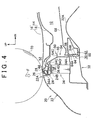
FIG 4 is an enlarged cross-sectional view corresponding to the 4-4 cross-section inFIG. 1 (4L-4L cross-section inFIG. 2 ); -
FIG 5 is a cross-sectional view showing the condition in which, as a result of a collision with an object, there the front fender or the like is deformed; -
FIG 6 is a graph showing the relationship between the acceleration and the displacement when an impactor collides with the boundary part; and -
FIG 7 is a cross-sectional view showing the vehicle front structure according to a second embodiment of the present invention. - In the following description, the present invention will be described in more detail in terms of exemplary embodiments.
- The first embodiment of the present invention will now be described. In the drawings, the UP, FR, and IN arrows represent the vehicle upward direction, vehicle front direction, and vehicle inward direction (in the transverse direction), respectively.
- As shown in
FIG 1 , ahood 14 made of metal is disposed in the vehicle upward direction above theengine room 12 so as to be able to open theengine compartment 12. As shown inFIG. 3 , thehood 14 includes a hoodouter panel 16 forming the outer sheet of thehood 14, and a hoodinner panel 18 forming the inner sheet of thehood 14. The outer peripheral part of the hoodouter panel 16 is joined by hemming to the hoodinner panel 18. - As shown in
FIG. 1 , anouter wall part 22 of thefront fender panel 20 is disposed on the side of the hoodouter panel 16, that is, on the side of thevehicle front 10. Theboundary part 26 between the hoodouter panel 16 that forms the outer sheet of thehood 14 and thefront fender panel 20 that forms the side of thevehicle front 10 extends substantially along the longitudinal direction of the vehicle at both end parts of thehood 14 in the transverse direction. - As shown in
FIG. 3 , thefront fender panel 20 includes an outerside wall part 22 that forms a designed surface that covers the top of the front wheel 19 (refer toFIG. 1 ), and aninner wall part 24 that hangs downward and is curved substantially in the vehicle downward direction (engine compartment 12 side) from theupper end part 22A of theouter wall part 22 at theboundary part 26 with the hoodouter panel 16. Theinner wall part 24 as the inner end part of thefront fender panel 20 has an innervertical wall part 24A hanging downward in substantially the vehicle downward direction from theupper end part 22A of theouter wall part 22, and ahorizontal flange part 24B extending outward substantially horizontally toward theengine compartment 12 side from the lower end part of the innervertical wall part 24A. The distal end part of thehorizontal flange part 24B, that is, theinner end part 24C of thefront fender panel 20, is formed to have a semicircular cross-section that is convex in the vehicle upward direction. A sealingmaterial 28 made of a resilient material (rubber) is disposed on the vehicle inner side of the innervertical wall part 24A, and makes pressing contact in an elastically deformed condition with both ends of the outer peripheral part of thehood 14 in the transverse direction. - An apron
upper member 30 that forms a part of the vehicle body is disposed on the lower side of thehorizontal flange part 24B of thefront fender panel 20. The apronupper member 30 is a vehicle body framework member that is disposed with its long direction in the substantially longitudinal direction of the vehicle on the inside in the transverse direction of theoutside wall 22 of thefront fender panel 20, having a cross-sectional shape that is open toward the lower direction of the vehicle, and being fused onto anapron sub-assembly 32 at the lower side. Theapron sub-assembly 32 extends in the transverse direction below the apronupper member 30 and, as shown inFIG 4 , has aprotruding part 32A facing toward the upper vehicle direction at an inside position in the transverse direction. - As shown in
FIG. 2 , ahorizontal flange part 24B of thefront fender panel 20 and the apronupper member 30 are linked by a shock-absorbingbracket 34 as a shock-absorbing part. A plurality of shock-absorbingbrackets 34 are disposed at a prescribed interval in substantially the longitudinal direction of the vehicle. By doing this, thehorizontal flange part 24B of thefront fender panel 20 is supported by the apronupper member 30 via the shock-absorbingbracket 34. - The shock-absorbing
bracket 34 is convex when viewed from the side of the vehicle, and includes afender mounting part 36, a front and rear pair of apronside mounting parts 38, and a front and rear pair ofsupport legs 40. Thefender mounting part 36 fixes thehorizontal flange part 24B of thefront fender panel 20 and thetop wall part 30B of the apronupper member 30. Theapron mounting part 38 is placed onto thetop wall part 30B of the apronupper member 30 in surface contact therewith, and fixed to the top allpart 30B by spot welding or the like. Thesupport legs 40 join the flat sheet fending mountingpart 36 and the flat sheet apronside mounting part 38 in the top-to-bottom vehicle direction, and can be deformed in the direction of crushing with respect to the action of a load acting from the upper direction of the vehicle. That is, the shock-absorbingbracket 34 links thehorizontal flange part 24B of thefront fender panel 20 to the apronupper member 30 and can deform in the direction of crushing with respect to the action of a load acting from the upper direction of the vehicle. - In this case, a bolt passage hole (not shown in the drawing) is passed through the
fender mounting part 36, and additionally aweld nut 42 is fused to the rear surface thereof. Thehorizontal flange part 24B of thefront fender panel 20 rests on the upper surface of thefender mounting part 36 and thebolt 44 is inserted from above thefender mounting part 36 and screwed into theweld nut 42. In this manner, thehorizontal flange part 24B of thefront fender panel 20 is mounted to thetop wall part 30B of the apronupper member 30 via the shock-absorbingbracket 34. - A
terminal part 24C on the inside of thefront fender panel 20 and afender protector 50 as a covering member are mounting to thehorizontal flange part 24B of thefront fender panel 20. Thefender protector 50 covers and hides the shock-absorbingbracket 34 from the inside in the transverse direction, and extends continuously in the substantially longitudinal direction of the vehicle. As shown inFIG. 3 , thefender protector 50 is mounted to thehorizontal flange part 24B of thefront fender panel 20 via aclip 58 made of resin, and hangs downward in the substantially downward direction of the vehicle with thedistal end 56 as a free end. Thefender protector 50 serving as a cover is formed as a single piece using a resin material, has a relatively low rigidity, and can deform elastically. - As shown in
FIG 2 andFIG. 3 , thebase end part 52 of thefender protector 50 is disposed at the above thehorizontal flange part 24B of thefront fender panel 20, and theupper surface 52A thereof is substantially parallel with thehorizontal flange part 24B. Thebase end part 52 of thefender protector 50 has integrally formed thereon, at a prescribed position on the lower surface side thereof, a substantially square hollow mountingseat 52B. The mountingseat 52B has one end (the left-side part inFIG 3 ) that is open and also hasside wall parts 152B and abase wall part 252B that is disposed substantially horizontally to join the lower ends of the side wall parts 152. The central part of thebase wall part 252B in the longitudinal direction of the vehicle has formed thereon a substantially rectangular mountingcutout 352B (refer toFIG. 3 ) facing from the outside in the transverse direction toward the inside in the transverse direction. - As shown in
FIG. 3 , theclip 58 is mounted to the mountingseat 52B by an elastically deformable engaging part 58A being inserted from the mountingcutout 352B to sandwich thebase wall part 252B and, with the semi-ellipticalsolid attachment part 58B being inserted through the clip attachment hole 124 formed in thehorizontal flange part 24B, a retaining tongue 58C is supported by the peripheral part of a clip attachment hole 124B. - A vehicle
body side structure 60 that includes the apronupper member 30 and awire harness protector 62 that is provided at a distance in the inside of the transverse direction from thevertical wall part 30A of the apronupper member 30 is disposed at the side below and the surrounding area around thedistal end 56 of thefender protector 50. The vehiclebody side structure 60 has aninsertion opening 64A formed substantially along the vehicle longitudinal direction in the vicinity of thedistal end 56 of thefender protector 50, and has a insertion part 64 (interpart insertion part) in the shape of an elongated channel into which thefender protector 50 can be inserted from theinsertion opening 64A when a load acts on theupper end part 22A of thefront fender panel 20 from the vehicle upper direction. Theinsertion part 64 is a gap formed in an interpart space formed by thevertical wall part 30A on the inside of the apronupper member 30 in the transverse direction and thevertical wall part 62A on the outside of thewire harness protector 62 in the vehicle longitudinal direction substantially along the vehicle longitudinal direction, the dimensions of the gap in theinsertion part 64 being set to be larger than the sheet thickness of thefender protector 50. - Although in this embodiment an
engine cover 68 made of resin is formed to include the side substantially above thewire harness protector 62, theengine cover 68 is set at a position that does not hinder the advance of thefender protector 50 when thefender protector 50 is inserted into theinsertion part 64. - A
guide part 56A is provided in thedistal end 56 as a guide means that is bent toward the inside in the transverse direction. Theguide part 56A has a shape that facilitates the sliding of thefender protector 50 into theinsertion part 64. Specifically, the end part thereof is a shape that is directed toward theinsertion part 64, and when a load acts on theupper end 22A of thefront fender panel 20 from the upward vehicle direction, by causing thedistal end 56 to slide in the downward vehicle direction from the vicinity of theinsertion opening 64A, thefender protector 50 is guided toward theinsertion part 64. - The
intermediate part 54 between thebase end part 52 and thedistal end 56 of thefender protector 50 includes an intermediateupper part 54A that is bent in the vehicle downward direction from the end part of thebase end part 52 in the transverse direction so as to extend at an inclination on the inside in the transverse direction, and an intermediatelower part 54B that is bent at a bendingpart 54C from the lower end part of the intermediateupper part 54A and that extends substantially in the vehicle downward direction. - A
notch 54D is formed in the bendingpart 54C of theintermediate part 54 of thefender protector 50, and the bendingpart 54C with thenotch 54D formed therein is aweak part 55 that serves as the origin point for bending deformation substantially in the transverse direction. The dimension L1 from thelowermost end position 64B to theinsertion opening 64A of theinsertion part 64 and the dimension L2 from thedistal end 56 to theweak part 55 of thefender protector 50 are set so that the relationship L2≥L1 is satisfied. - Next, the operation and effect of the above-noted embodiment will be described.
- As shown in
FIG. 2 , the shock-absorbingbracket 34 not only links thehorizontal flange part 24B of thefront fender panel 20 and the apronupper member 30 at a part that is substantially in the vehicle longitudinal direction, but also can deform in the direction of crushing under the action of a load acting from the upward vehicle direction. According to this configuration, when the collidingbody 70 shown inFIG. 4 collides with the boundary part between theupper end part 22A of thefront fender panel 20 and the hoodouter panel 16 from the vehicle upward direction, as shown inFIG 5 , the force of impact F when that occurs causes the shock-absorbingbracket 34 to deform so as to be crushed, thereby absorbing the energy at the time of the collision. - Also, as shown in
FIG. 2 , theterminal part 24C on the inside of thefront fender panel 20 and the shock-absorbingbracket 34 are covered and hidden from the inside in the transverse direction by thefender protector 50 that extends continuously in the substantially longitudinal direction of the vehicle. For example, when the hood 14 (refer toFIG 1 ) is opened, theterminal part 24C on the inside of thefront fender panel 20 and the shock-absorbingbracket 34 cannot be visually verified from the front side of the vehicle. For this reason, appearance is good. - Also, as shown in
FIG. 3 , in theinsertion part 64 of the vehiclebody side structure 60 in which is formed aninsertion opening 64A along the substantially longitudinal direction of the vehicle in the vicinity of thedistal end 56 of thefender protector 50, thefender protector 50 is inserted from theinsertion opening 64A when a collision of a collidingbody 70 occurs, in which a load acts from the vehicle upward direction on the upper end part of thefront fender panel 20. For this reason, when a collision occurs with the collidingbody 70, as shown inFIG. 5 , even if thefront fender panel 20 and the shock-absorbingbracket 34 deform, by thefender protector 50 being inserted into theinsertion part 64, there is almost no repulsing force from thefender protector 50 toward thefront fender panel 20. - In this case, because the
guide part 56A guides thefender protector 50 toward theinsertion part 64 at the time of a collision with the collidingbody 70, as shown inFIG 3 , even in the case, for example, in which the relative position of thedistal end 56 of thefender protector 50 with respect to theinsertion part 64 is offset in the assembled condition, variation in the relative position of thefender protector 50 with respect to theinsertion part 64 is tolerated, and thefender protector 50 is smoothly inserted so as to slide toward theinsertion part 64. - As a further explanation, because the
fender protector 50 is a resin part, some small variation in dimensions (for example, 1 mm to 2 mm) may occur, and a positional adjustment of thefront fender panel 20 and the hood 14 (adjustment when placing thefront fender panel 20 in place) may cause a variation in the relative position between thefront fender panel 20 and the vehicle body side structure 60 (including the apron upper member 30). According to this embodiment, however, even if these cause a slight shift in the relative position of thefender protector 50 with respect to theinsertion part 64 from the proper position indicated in the drawings, theguide part 56A can cause thefender protector 50 to slide into theinsertion part 64. - Because the
weak part 55 that serves as the origin point for bending deformation toward substantially in the transverse direction is provided at theintermediate part 54 of thefender protector 50, when a collision occurs with the collidingbody 70, even if thedistal end 56 of thefender protector 50 comes into contact with the vehiclebody side structure 60 at the stage at which thedistal end 56 is inserted into theinsertion part 64, thefender protector 50 is successively inserted into theinsertion part 64 as it bends slightly with theweak part 55 as the origin, thereby effectively suppressing repulsive force toward thefront fender panel 20. - Because the dimension L1 from the
lowermost end position 64B to theinsertion opening 64A of theinsertion part 64 and the dimension L2 from thedistal end 56 to theweak part 55 of thefender protector 50 are set so that the relationship L2≥L1 is satisfied, when a collision occurs with the collidingbody 70, thedistal end 56 of thefender protector 50 is inserted until it reaches thelowermost end position 64B of theinsertion part 64, after which, with thefender protector 50 hitting bottom at thelowermost end position 64B of theinsertion part 64, there is bending deformation with a low load toward substantially the transverse direction with theweak part 55 as the origin. That is, because the bending deformation of thefender protector 50 at low load occurs after the insertable dimension of theinsertion part 64 is fully used, it is possible to effectively maintain the deformation stroke amount of thefront fender panel 20. - As shown schematically by
FIG 6 , which shows the relationship the displacement (S) of the fender protector and the deformation acceleration (G) (hereinafter "G-S curve"), compared to the comparison structure in which the distal end of the fender protector is fixed to the apron upper member (shown by the dotted line G-S), because there is almost no repulsing force by the deformation of thefender protector 50, the acceleration (load) in the latter half of the waveform is reduced and it is possible to obtain good acceleration (region surrounded by the single dot-dash line inFIG. 6 ), and, because there is little residual uncrushed amount, it is also possible to achieve stroke more reliably. - As described above, according to the vehicle front part structure of this embodiment, it is possible to achieve a good load stroke at the time of a collision with the colliding body as shown in
FIG 4 andFIG 5 , while achieving a good appearance on the inside of thefront fender panel 20 shown inFIG. 2 , - The second embodiment of the present invention will next be described with reference to
FIG 7 . A feature of the second embodiment, as shown inFIG. 7 , is that vehicle body side structure (engine cover 80) is formed as a single member, with other aspects of the configuration being substantially the same as the first embodiment. Constituent elements that are substantially the same as in the first embodiment are assigned the same reference numerals and the description thereof are omitted herein. - As shown in
FIG 7 , the engine cover (built-in part) 80 as the vehicle body side structure is provided so as to extend as far as a part of the apronupper member 30 toward the inside in the transverse direction, and has aninsertion opening 82A that is formed along the substantially longitudinal direction of the vehicle approaching thedistal end 56 of thefender protector 50, and aninsertion part 82 in the form of an elongated channel into which thefender protector 50 can slide into from theinsertion opening 82A (from theinsertion part 56 side). That is, theengine cover 80 can accept thefender protector 50 inside the channel-shapedinsertion part 82. With this type of configuration as well, the same type of operation and effect are achieved as with the first embodiment. - Although in the above-noted embodiments the structure is such that the
fender protector 50 is slid into theinsertion parts upper end part 22A of thefront fender panel 20 from above the colliding body relative to the vehicle, alternatively, for example, a structure may be adopted in which, when the load acts, the distal end side of the covering member is inserted into the insertion part without coming into contact with the vicinity of the insertion opening or the inner wall of the insertion part. - Also, although in the above-noted embodiments the shock-absorbing
bracket 34 as the shock-absorbing part links thehorizontal flange part 24B of thefront fender panel 20 with the apronupper member 30, alternatively a structure may be adopted in which a shock-absorbing part capable of deformation in the crushing direction with respect to a load acting from above relative to the vehicle, is fixed, for example, the terminal part side on the inside of the fender panel, is fixed to the apron upper member, the end part of the inside of the fender panel may be a vertical wall part forming a art of the end part of the inside of the fender panel. - Also, while a configuration is preferable in which the
distal end 56 of thefender protector 50 is provided with aguide part 56A as a guide means, a configuration in which there is no guide means may be adopted, and a configuration may be adopted in which a different guide means such as one that guides a covering member toward the insertion part when a load acts from above relative to the vehicle on the upper end part of the fender panel is provided on a part of the vehicle body side structure. - Additionally, although in the above-noted embodiments a configuration is preferable in which a
weak part 55 is provided in theintermediate part 54 of thefender protector 50, such as shown inFIG 3 , a configuration may be adopted in which a weak part is not provided in the intermediate part of the covering member. Although theweak part 55 in the above-noted embodiments has anotch 54D formed in the bendingpart 54C, as long as the weak part is a part that forms the origin of bending deformation in bending in substantially the transverse direction, the weak point may be another weak point, such as simply a bending part, a part having thin material, or a formed part having a small hole. - Additionally, while in the above-noted embodiments the dimension L1 from the
lowermost end position 64B to theinsertion opening 64A of theinsertion part 64 and the dimension L2 from thedistal end 56 to theweak part 55 of thefender protector 50 are set so that the relationship L2≥L1 is satisfied and this type of configuration is preferred, an alternate configuration may be adopted in which the dimension L2 is slightly shorter than L1, for example, so that the relationship L2≥L1 is not satisfied. - Although in the above-noted embodiments are described for the example in which the intermediate
upper part 54A of thefender protector 50 is inclined downward toward the inside of the transverse direction, the intermediate upper part of the covering member may extend in the downward vehicle direction at an inclination toward the outside in the transverse direction. Also, although in the above-noted embodiments the intermediatelower part 54B of thefender protector 50 extends substantially in the downward vehicle direction, the lower part of the intermediate part of the covering member may alternatively extend in the downward vehicle direction at an inclination toward either the outside or the inside in the transverse direction. - In the above-noted embodiments, although the inner wall part 24 (inside end part) of the
front fender panel 20 is bent in substantially the downward vehicle direction at the boundary part with the hood outer panel 16 (hood panel), the inside end part of the fender panel may, for example, be bent substantially in the downward vehicle direction so that it is provided substantially horizontally, bent toward the inside in the transverse direction at the boundary part with the hood panel. - While the invention has been described with reference to exemplary embodiments thereof, it should be understood that the invention is not limited to the exemplary embodiments or constructions. To the contrary, the invention is intended to cover various modifications and equivalent arrangements. In addition, while the various elements of the exemplary embodiments are shown in various combinations and configurations, which are exemplary, other combinations and configurations, including more, fewer, or only a single element, are also within the spirit and scope of the invention.
Claims (12)
- A vehicle front structure characterized by comprising:a fender panel (20) having an outer wall (22) that forms a side of the vehicle front (10), an inside end part being bent at a boundary part with a hood panel;an apron upper member (30) that extends in substantially the vehicle longitudinal direction, parallel to the outer wall (22) of the fender panel (20) ;a shock-absorbing part (34) that links an inside end of the fender panel (20) and the apron upper member (30);a cover member (50), the base end (52) of which is mounted on the inside of the fender panel (20) and that hangs downward as a free end in the substantially downward direction of the vehicle, covers the distal end (56) on the inside of the fender panel (20) and the shock-absorbing part (34), and extends in substantially the direction transverse direction of the vehicle; anda vehicle side-structure (60, 80) that includes an insertion part (64, 82) formed in substantially the vehicle longitudinal direction near the distal end (56) of the cover member (50), and into which the cover member (50) may be inserted from above.
- The vehicle body vehicle front structure according to claim 1, wherein the shock-absorbing part (34) forms a part of the inside end part of the fender panel (20).
- The vehicle front structure according to claim 1 or 2, wherein the cover member (50) is a guide means that guides the cover member (50) toward the insertion part (64, 82) of the vehicle side-structure (60, 80).
- The vehicle front structure according to claim 3, wherein the guide means is formed with an end that is directed toward the insertion part (64, 82) of the vehicle body side structure.
- The vehicle front structure according to any one of claim 1 to claim 4, wherein the cover member (50) has a weak part that serves as the origin point for bending deformation substantially in the transverse direction, formed in an intermediate part between the base end (52) and the distal end (56).
- The vehicle front structure according to claim 5, wherein the cover member (50) has a cutaway part in the weak part.
- The vehicle front structure according to claim 5, wherein the cover member (50) is formed by bending at the weak part.
- The vehicle front structure according to claim 5, wherein the cover member (50) is formed with thin material at the weak part.
- The vehicle front structure according to claim 5, wherein the cover member (50) has one or a plurality of weak parts.
- The vehicle front structure according to any one of claim 5 to claim 9, wherein a dimension L1 from the lowermost end position to the insertion opening of the insertion part (64, 82) and a dimension L2 from the distal end (56) to the weak part of the cover member (50) are set so that the relationship L2≥L1 is satisfied.
- The vehicle front structure according to any one of claim 1 to claim 10, wherein the vehicle body side structure is formed by a plurality of members and the insertion part (64, 82) is formed as a gap between the plurality of members.
- The vehicle front structure according to any one of claim 1 to claim 10, wherein the vehicle body side structure is formed by one member, and the insertion part (64, 82) is formed as a channel in the member.
Applications Claiming Priority (1)
| Application Number | Priority Date | Filing Date | Title |
|---|---|---|---|
| JP2007046177A JP4251221B2 (en) | 2007-02-26 | 2007-02-26 | Body front structure |
Publications (3)
| Publication Number | Publication Date |
|---|---|
| EP1961628A2 true EP1961628A2 (en) | 2008-08-27 |
| EP1961628A3 EP1961628A3 (en) | 2010-09-08 |
| EP1961628B1 EP1961628B1 (en) | 2012-03-28 |
Family
ID=39535227
Family Applications (1)
| Application Number | Title | Priority Date | Filing Date |
|---|---|---|---|
| EP08002968A Expired - Fee Related EP1961628B1 (en) | 2007-02-26 | 2008-02-18 | Vehicle front structure |
Country Status (4)
| Country | Link |
|---|---|
| US (1) | US7497503B2 (en) |
| EP (1) | EP1961628B1 (en) |
| JP (1) | JP4251221B2 (en) |
| CN (1) | CN101254798B (en) |
Cited By (1)
| Publication number | Priority date | Publication date | Assignee | Title |
|---|---|---|---|---|
| FR3063480A1 (en) * | 2017-03-03 | 2018-09-07 | Peugeot Citroen Automobiles Sa | IMPROVED SEAL SUPPORT OF VEHICLE HOOD COVER |
Families Citing this family (11)
| Publication number | Priority date | Publication date | Assignee | Title |
|---|---|---|---|---|
| EP1892162A3 (en) * | 2006-08-21 | 2009-12-02 | Alutech Gesellschaft m.b.H. | Pedestrian protection for a motor vehicle |
| US20090194348A1 (en) * | 2008-01-31 | 2009-08-06 | Faubert Robert J | Automotive hood-hinge system |
| US8182027B2 (en) * | 2009-06-15 | 2012-05-22 | Toyota Motor Engineering & Manufacturing North America, Inc. | Fender structure assemblies for vehicles |
| JP5482608B2 (en) * | 2010-09-30 | 2014-05-07 | 豊田合成株式会社 | Weather strip |
| JP5751238B2 (en) * | 2012-11-05 | 2015-07-22 | トヨタ自動車株式会社 | Fender support structure |
| BR112016009484B1 (en) * | 2013-11-13 | 2022-04-19 | Aisin Seiki Kabushiki Kaisha | INTERNAL COMBUSTION ENGINE AND COVER ELEMENT FIXING STRUCTURE FOR THE INTERNAL COMBUSTION ENGINE |
| US9902434B2 (en) | 2015-07-30 | 2018-02-27 | Toyota Motor Engineering & Manufacturing North America, Inc. | Offset deforming fender attachment bracket |
| US9630581B2 (en) | 2015-08-17 | 2017-04-25 | Toyota Motor Engineering & Manufacturing North America, Inc. | Vehicles with fender structure assemblies and deforming fender attachment brackets |
| JP6299730B2 (en) * | 2015-11-06 | 2018-03-28 | マツダ株式会社 | Vehicle side body structure |
| USD792290S1 (en) * | 2016-01-12 | 2017-07-18 | GM Global Technology Operations LLC | Vehicle grille |
| JP6511030B2 (en) * | 2016-10-20 | 2019-05-08 | 本田技研工業株式会社 | Hood support structure of car |
Citations (1)
| Publication number | Priority date | Publication date | Assignee | Title |
|---|---|---|---|---|
| JP2005014763A (en) | 2003-06-26 | 2005-01-20 | Toyota Motor Corp | Fender panel mounting structure |
Family Cites Families (14)
| Publication number | Priority date | Publication date | Assignee | Title |
|---|---|---|---|---|
| JP3518233B2 (en) * | 1997-03-19 | 2004-04-12 | 三菱自動車工業株式会社 | Vehicle hood device |
| JP4250852B2 (en) | 2000-03-31 | 2009-04-08 | トヨタ自動車株式会社 | Vehicle fender structure |
| JP4244497B2 (en) * | 2000-05-17 | 2009-03-25 | トヨタ自動車株式会社 | Vehicle cowl structure |
| KR100371278B1 (en) * | 2000-11-30 | 2003-02-07 | 현대자동차주식회사 | Fender panel impact absorption structure with walker protection function in car |
| DE10102187A1 (en) * | 2001-01-16 | 2002-08-01 | Volkswagen Ag | Impact damping mudguard for a vehicle comprises a support element which is made of a hard, almost inflexible material, and is divided by a fold line into two sections forming an obtuse angle |
| JP4762438B2 (en) * | 2001-05-18 | 2011-08-31 | 富士重工業株式会社 | Front body structure of the vehicle |
| JP4192452B2 (en) * | 2001-09-18 | 2008-12-10 | トヨタ自動車株式会社 | Vehicle fender structure |
| JP3838125B2 (en) | 2002-03-15 | 2006-10-25 | 日産自動車株式会社 | Fender structure |
| JP3876742B2 (en) * | 2002-03-27 | 2007-02-07 | トヨタ自動車株式会社 | Energy absorption structure |
| JP4120464B2 (en) * | 2003-05-13 | 2008-07-16 | マツダ株式会社 | Front body structure of the vehicle |
| JP3991916B2 (en) * | 2003-05-14 | 2007-10-17 | マツダ株式会社 | Front body structure of the vehicle |
| FR2855810B1 (en) * | 2003-06-03 | 2005-07-29 | Plastic Omnium Cie | WING SUPPORT FOR MOTOR VEHICLE |
| JP2005075176A (en) * | 2003-09-01 | 2005-03-24 | Toyota Motor Corp | Vehicle hood structure |
| JP4449523B2 (en) * | 2004-03-24 | 2010-04-14 | マツダ株式会社 | Resin vehicle parts |
-
2007
- 2007-02-26 JP JP2007046177A patent/JP4251221B2/en not_active Expired - Fee Related
-
2008
- 2008-02-14 US US12/071,031 patent/US7497503B2/en not_active Expired - Fee Related
- 2008-02-18 EP EP08002968A patent/EP1961628B1/en not_active Expired - Fee Related
- 2008-02-26 CN CN2008100063486A patent/CN101254798B/en not_active Expired - Fee Related
Patent Citations (1)
| Publication number | Priority date | Publication date | Assignee | Title |
|---|---|---|---|---|
| JP2005014763A (en) | 2003-06-26 | 2005-01-20 | Toyota Motor Corp | Fender panel mounting structure |
Cited By (1)
| Publication number | Priority date | Publication date | Assignee | Title |
|---|---|---|---|---|
| FR3063480A1 (en) * | 2017-03-03 | 2018-09-07 | Peugeot Citroen Automobiles Sa | IMPROVED SEAL SUPPORT OF VEHICLE HOOD COVER |
Also Published As
| Publication number | Publication date |
|---|---|
| JP4251221B2 (en) | 2009-04-08 |
| US20080203763A1 (en) | 2008-08-28 |
| CN101254798B (en) | 2010-04-21 |
| EP1961628A3 (en) | 2010-09-08 |
| JP2008207670A (en) | 2008-09-11 |
| US7497503B2 (en) | 2009-03-03 |
| EP1961628B1 (en) | 2012-03-28 |
| CN101254798A (en) | 2008-09-03 |
Similar Documents
| Publication | Publication Date | Title |
|---|---|---|
| EP1961628B1 (en) | Vehicle front structure | |
| EP2163460B1 (en) | Front structure of automobile hood | |
| JP4353119B2 (en) | Body front structure | |
| EP1258417B1 (en) | Front body structure for vehicle | |
| JP4380565B2 (en) | Side impact load transmission structure | |
| JP5407372B2 (en) | Vehicle side body structure | |
| KR101557798B1 (en) | Hood structure for vehicle | |
| JP5899937B2 (en) | Mounting structure for automotive door trim | |
| US20060237998A1 (en) | Stop support for the front hood of a motor vehicle | |
| JP4978253B2 (en) | Fender cover structure and front body structure | |
| KR20080052754A (en) | Cowl side part reinforcement structure of vehicle | |
| JP2009161141A (en) | Body front structure | |
| JP2007185996A (en) | Front structure of automobile hood | |
| JP4036219B2 (en) | Automotive engine hood structure | |
| CN110719861A (en) | Vehicle body front structure | |
| JP2009045996A (en) | Four-wheel vehicle cowl structure | |
| JP2008179192A (en) | Arrangement structure of airbag device | |
| JPH07329570A (en) | Vehicle door structure | |
| JP7567654B2 (en) | Vehicle interior materials | |
| JP2010260510A (en) | Vehicle door structure | |
| JP2006306121A (en) | Vehicle fender panel support structure | |
| JP2010158940A (en) | Cowl top garnish | |
| JP2005335500A (en) | Fender structure for vehicles | |
| JP2007508200A (en) | Pre-formed body parts to reduce pedestrian impact | |
| JP2019107985A (en) | Cowl top garnish |
Legal Events
| Date | Code | Title | Description |
|---|---|---|---|
| PUAI | Public reference made under article 153(3) epc to a published international application that has entered the european phase |
Free format text: ORIGINAL CODE: 0009012 |
|
| 17P | Request for examination filed |
Effective date: 20080218 |
|
| AK | Designated contracting states |
Kind code of ref document: A2 Designated state(s): AT BE BG CH CY CZ DE DK EE ES FI FR GB GR HR HU IE IS IT LI LT LU LV MC MT NL NO PL PT RO SE SI SK TR |
|
| AX | Request for extension of the european patent |
Extension state: AL BA MK RS |
|
| PUAL | Search report despatched |
Free format text: ORIGINAL CODE: 0009013 |
|
| AK | Designated contracting states |
Kind code of ref document: A3 Designated state(s): AT BE BG CH CY CZ DE DK EE ES FI FR GB GR HR HU IE IS IT LI LT LU LV MC MT NL NO PL PT RO SE SI SK TR |
|
| AX | Request for extension of the european patent |
Extension state: AL BA MK RS |
|
| RIC1 | Information provided on ipc code assigned before grant |
Ipc: F16F 7/12 20060101ALI20100730BHEP Ipc: B60R 21/34 20060101AFI20080714BHEP |
|
| AKX | Designation fees paid |
Designated state(s): DE FR GB |
|
| GRAP | Despatch of communication of intention to grant a patent |
Free format text: ORIGINAL CODE: EPIDOSNIGR1 |
|
| RIC1 | Information provided on ipc code assigned before grant |
Ipc: B60R 21/34 20110101AFI20110816BHEP Ipc: F16F 7/12 20060101ALI20110816BHEP |
|
| GRAS | Grant fee paid |
Free format text: ORIGINAL CODE: EPIDOSNIGR3 |
|
| RIN1 | Information on inventor provided before grant (corrected) |
Inventor name: ITO, KATSUYOSHI |
|
| GRAA | (expected) grant |
Free format text: ORIGINAL CODE: 0009210 |
|
| AK | Designated contracting states |
Kind code of ref document: B1 Designated state(s): DE FR GB |
|
| REG | Reference to a national code |
Ref country code: GB Ref legal event code: FG4D |
|
| REG | Reference to a national code |
Ref country code: DE Ref legal event code: R096 Ref document number: 602008014367 Country of ref document: DE Effective date: 20120524 |
|
| REG | Reference to a national code |
Ref country code: GB Ref legal event code: 746 Effective date: 20121112 |
|
| REG | Reference to a national code |
Ref country code: DE Ref legal event code: R084 Ref document number: 602008014367 Country of ref document: DE Effective date: 20121115 |
|
| PLBE | No opposition filed within time limit |
Free format text: ORIGINAL CODE: 0009261 |
|
| STAA | Information on the status of an ep patent application or granted ep patent |
Free format text: STATUS: NO OPPOSITION FILED WITHIN TIME LIMIT |
|
| RAP2 | Party data changed (patent owner data changed or rights of a patent transferred) |
Owner name: TOYOTA JIDOSHA KABUSHIKI KAISHA |
|
| 26N | No opposition filed |
Effective date: 20130103 |
|
| REG | Reference to a national code |
Ref country code: DE Ref legal event code: R097 Ref document number: 602008014367 Country of ref document: DE Effective date: 20130103 |
|
| REG | Reference to a national code |
Ref country code: FR Ref legal event code: PLFP Year of fee payment: 8 |
|
| PGFP | Annual fee paid to national office [announced via postgrant information from national office to epo] |
Ref country code: DE Payment date: 20150210 Year of fee payment: 8 |
|
| PGFP | Annual fee paid to national office [announced via postgrant information from national office to epo] |
Ref country code: FR Payment date: 20150210 Year of fee payment: 8 Ref country code: GB Payment date: 20150218 Year of fee payment: 8 |
|
| REG | Reference to a national code |
Ref country code: DE Ref legal event code: R119 Ref document number: 602008014367 Country of ref document: DE |
|
| GBPC | Gb: european patent ceased through non-payment of renewal fee |
Effective date: 20160218 |
|
| REG | Reference to a national code |
Ref country code: FR Ref legal event code: ST Effective date: 20161028 |
|
| PG25 | Lapsed in a contracting state [announced via postgrant information from national office to epo] |
Ref country code: GB Free format text: LAPSE BECAUSE OF NON-PAYMENT OF DUE FEES Effective date: 20160218 Ref country code: DE Free format text: LAPSE BECAUSE OF NON-PAYMENT OF DUE FEES Effective date: 20160901 Ref country code: FR Free format text: LAPSE BECAUSE OF NON-PAYMENT OF DUE FEES Effective date: 20160229 |