EP1961496A1 - Garbage treatment device - Google Patents
Garbage treatment device Download PDFInfo
- Publication number
- EP1961496A1 EP1961496A1 EP06834708A EP06834708A EP1961496A1 EP 1961496 A1 EP1961496 A1 EP 1961496A1 EP 06834708 A EP06834708 A EP 06834708A EP 06834708 A EP06834708 A EP 06834708A EP 1961496 A1 EP1961496 A1 EP 1961496A1
- Authority
- EP
- European Patent Office
- Prior art keywords
- water
- crushing
- supplied
- trap pipe
- garbage disposal
- Prior art date
- Legal status (The legal status is an assumption and is not a legal conclusion. Google has not performed a legal analysis and makes no representation as to the accuracy of the status listed.)
- Withdrawn
Links
- XLYOFNOQVPJJNP-UHFFFAOYSA-N water Substances O XLYOFNOQVPJJNP-UHFFFAOYSA-N 0.000 claims abstract description 122
- 238000000034 method Methods 0.000 claims abstract description 102
- 238000007599 discharging Methods 0.000 abstract description 44
- 239000002245 particle Substances 0.000 abstract description 35
- 230000000694 effects Effects 0.000 abstract description 3
- 239000008399 tap water Substances 0.000 description 15
- 235000020679 tap water Nutrition 0.000 description 15
- 238000001514 detection method Methods 0.000 description 13
- 244000126211 Hericium coralloides Species 0.000 description 7
- 238000010586 diagram Methods 0.000 description 2
- 239000011295 pitch Substances 0.000 description 2
- 210000000988 bone and bone Anatomy 0.000 description 1
- 239000000835 fiber Substances 0.000 description 1
- 239000002184 metal Substances 0.000 description 1
- 229910052751 metal Inorganic materials 0.000 description 1
- 230000000149 penetrating effect Effects 0.000 description 1
- 238000003756 stirring Methods 0.000 description 1
Images

Classifications
-
- E—FIXED CONSTRUCTIONS
- E03—WATER SUPPLY; SEWERAGE
- E03C—DOMESTIC PLUMBING INSTALLATIONS FOR FRESH WATER OR WASTE WATER; SINKS
- E03C1/00—Domestic plumbing installations for fresh water or waste water; Sinks
- E03C1/12—Plumbing installations for waste water; Basins or fountains connected thereto; Sinks
- E03C1/26—Object-catching inserts or similar devices for waste pipes or outlets
- E03C1/266—Arrangement of disintegrating apparatus in waste pipes or outlets; Disintegrating apparatus specially adapted for installation in waste pipes or outlets
Definitions
- the present invention relates to a garbage disposal apparatus which is applicable to kitchen facilities. More specifically, it relates to the one that can prevent any crushed particles from being left in a trap pipe by supplying rinse water not only after crushing process but also during the crushing process, if the rinse water is supplied to the trap pipe which connects to a drain side of the garbage disposal apparatus main body, in addition to a water supply of crush water to the garbage disposal apparatus main body.
- garbage disposal apparatuses of a hammer mill type and a grinder type have been known.
- the garbage disposal apparatus of hammer mill type has a fixed hammer or a slidable hammer on a disk arranged at a bottom of a cylindrical hopper. Garbage thrown into the hopper has been pressed against an inner circumferential surface of the hopper by centrifugal force that occurs due to a revolution of the disk so that the garbage can be crushed by the hammer. The crushed garbage has then fallen down through grooves formed in a wall surface of the hopper or a gap between an outer edge of the disk and the inner circumferential surface of the hopper. The crushed garbage, which has fallen down, has, then, drained into a side of drain pipe thereof.
- the garbage disposal apparatus of hammer mill type has been designed to drive the disk which installs the hammer for crushing the garbage in the hopper, at high speed of several thousands of revolutions (rpm) so that it produces any hideous noises and/or vibrations because the garbage collides with the hammer and the inner circumferential surface of the hopper so as to be crushed.
- a crushing unit in which a rotary blade and a fixed blade, each having comb-tooth shaped blades, have been laminated alternately. It has been configured so that these rotary blade and fixed blade constituting the crushing unit can be engaged with each other with small spacing held between them, thereby revolving the rotary blade to crush the garbage with the garbage being gripped by the rotary blade and fixed blade. Blades of the laminated rotary blade and fixed blade have finer pitches in proportion to the lower laminated layer.
- This garbage disposal apparatus of grinder type having such a configuration that these rotary blades and fixed blades are laminated has not required any centrifugal force, thereby allowing it to produce low noise by controlling number of revolutions.
- tap water used as any processing water for enabling crushed particles of the garbage to fall down may be supplied under automatic control.
- the processing water hereinafter, referred to as "crush water"
- the processing water is automatically supplied into a housing provided in the garbage disposal apparatus main body.
- the garbage disposal apparatus of this type is disposed with it being installed in a kitchen sink, between the housing and a drain pipe, a trap pipe is generally connected to them. With a view of discharging any crushed particles left in the trap pipe therefrom and rinsing the inside thereof, rinse water may be supplied apart from the crush water.
- the present invention has thus solved such the conventional problem and has provided a garbage disposal apparatus that can prevent any crushed particles from being left in the trap pipe, when crushing process of the garbage and rinsing process of crushed particles are carried out using the rinse water in addition to the crush water, by particularly making the rinse water supply timing not only after the crushing process but also during the crushing process.
- the present invention by supplying the rinse water to the trap pipe during the crushing process, it is possible to increase any discharge effect on the crushed particles and to prevent the crushed particles from being left in the trap pipe. Further, at the same time, it is possible to rinse inside of the trap pipe by a stream of water flown into the trap pipe.
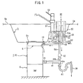
- FIG. 1 shows a conception diagram of a case where this invention is applied to a tap water supply system for the garbage disposal apparatus 1 that is installed in a kitchen sink for household use.
- the garbage disposal apparatus 1 is fixed on and installed in a drain opening So provided in almost middle of a bottom of a kitchen sink S on its rear side of the bottom.
- the garbage disposal apparatus 1, which will be described later, has a tubular hopper 3 in which a crushing unit is provided.
- the crushing unit is rotatably driven by a motor 6.
- the above-mentioned hammer mill typed one that crushes the garbage using a hammer mill, the grinder typed one that crushes the garbage using rotary blade and fixed blade, and the like can be used.
- the following embodiments relate to the garbage disposal apparatus using the latter (grinder type).
- a supply port 9 for the tap water and a connecting pipe 10 that is connected to this supply port 9 are respectively connected.
- a drain-pipe-connecting port 21 is provided, and through this drain-pipe-connecting port 21, the crushed garbage, crush water (water for allowing the crushed particles to flow downward) used when crushing it and the like are discharged to a drain pipe 39.
- Well-known trap pipe for example, S trap pipe 40
- S trap pipe 40 is connected to the drain-pipe-connecting port 21 and the drain pipe 39.
- a branching pipe 41 is provided between the S trap pipe 40 and the drain-pipe-connecting port 21, between the S trap pipe 40 and the drain-pipe-connecting port 21, a branching pipe 41 is provided.
- the branching pipe 41 has around T-shape and a first branching pipe 41a is connected to the above-mentioned S trap pipe 40 as well as at a side of a second branching pipe 41b that is connected to the S trap pipe 40 on a vertical line, an ejection water-supplying portion 42 acting as ejection water-supplying means of the rinse water is connected.
- This ejection water-supplying portion 42 is provided for preventing any crushed particles from being left in the S trap pipe 40 and supplies the rinse water to the S trap pipe 40 to discharge the particles left in the pipe and to rinse inside of the trap pipe.
- a sink in which a step portion 50 is provided at a one level lower hollowed portion than an upper flat surface (overflow edge) Sa is used as the kitchen sink S.
- a tap 51 is mounted and fixed on the step portion 50 so that it can stand projecting thereon.
- a handle 52 of the tap 51 open and close (stop) of the tap for tap water is carried out.
- Vacuum breaker 60 for the tap water to be supplied to the garbage disposal apparatus 1 is also provided on the step portion 50.
- the vacuum breaker 60 is provided for preventing the tap water and water (dirty water) at a side of the garbage disposal apparatus 1 from being directly mixed, and the tap water is once conducted to the vacuum breaker 60 and the tap water ejected from the vacuum breaker 60 is then conducted to the garbage disposal apparatus 1 and the S trap pipe 40.
- a first branching pipe 53a branched from a water main 53 is connected to the tap 51.
- Second and third branching pipes 53b, 53c branched from the water main 53 are respectively connected to connecting ports (tap water ports) for the tap water, which are provided on the vacuum breaker 60.
- a crush water open-and-close valve 55 and a rinse water open-and-close valve 57 are disposed on the second and third branching pipes 53b, 53c, by which water supply control thereof is performed.
- any electromagnetic valves are used for the crush water open-and-close valve 55 and the rinse water open-and-close valve 57.
- a water pipe 54 is connected to an ejection port relating to the second branching pipe 53b and the connecting pipe 10. It can be connected direct to the supply port 9 for the tap water, not through the connecting pipe 10.
- an air-open type one (atmospheric one) is used. Even if any negative pressure bringing a dirty water level to rise based on a water cutoff or the like acts on a side of the drain pipe, this vacuum breaker 60 can separate any tap water system from the dirty water system surely.
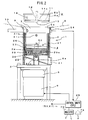
- FIG. 2 shows an embodiment of the garbage disposal apparatus 1, to which the present invention is applicable.
- This garbage disposal apparatus 1 has the hopper 3.
- the hopper 3 into which any garbage and the like are thrown is mounted on a base frame 2 and an upper edge of the hopper 3 is fit into the drain opening So of the kitchen sink S.
- the crushing unit 4 is installed so as to be detachably from the hopper 3.
- a crushing rotary blade which will be described later, is fit to a driving shaft 5a of a reduction unit 5 and the motor 6 installed in the base frame rotatively drives the crushing rotary blade of the crushing unit 4 through the reduction unit 5.
- the hopper 3 is provided with a throwing opening portion 7 at its upper end and a cap body 8 is placed into the throwing opening portion 7 so as to be detachable or attachable.
- the throwing opening portion 7 is provided with the above-mentioned supply port 9.
- the tap water is supplied to the cap body 8 through the supply port 9 and then, supplied from the cap body 8 into the hopper 3, which is used as the crush water.
- the cap body 8 is provided with an inner cap 8a and an upper cap 8b.
- the inner cap 8a has an opening at its upper portion and a cylinder shape with a bottom at its lower portion, so that a water-impinging portion 12 can be formed as to be projected from a bottom portion 11 and a plurality of water-supply ports 13 can be formed around the water-impinging portion 12.
- the water- impinging portion 12 and the water-supply ports 13 constitute water storage portion 11a.
- the water-supply ports 13 are formed all over the bottom portion 11 of the water storage portion 11a with them extending from an inner circumferential side thereof to an outer circumferential side thereof.
- the water-supply ports 13 may be arranged, for example, in a radial manner.
- the water storage portion 11a has a supply port 18 penetrating through a side portion of the inner cap 8a from its outer circumferential surface to its inner circumferential surface. Therefore, if the cap body 8 is fit into the throwing opening portion 7, the supply port 18 is formed so as to communicate with the supply port 9 of the hopper 3.
- the water-impinging portion 12 is configured so that a surface of its wall which stands from the bottom portion 11 can be formed at an opposite position to the supply port 18.
- the water-impinging portion 12 is disposed at a generally right angle to a water-discharging direction from the supply port 18 in its horizontal direction.
- a slant surface that is inclined towards a direction where its upper portion is positioned at an inner side is also formed in its vertical direction. This is because the water supplied into the cap body 8 is dispersed all over around it and fallen into the hopper 3.
- a bottom plate 22 that is inclined towards the drain-pipe-connecting port 21 and an opening 22a, through which the driving shaft 5a of the reduction unit 5 is passed, is formed at a center of the bottom plate 22.
- the cap body 8 by rotating the cap body 8 to a predetermined direction only by a predetermined angle with the cap body 8 being placed in the throwing opening portion 7, the cap body 8 achieves a locked state thereof.
- the cap body 8 is locked into the hopper 3.
- the garbage disposal apparatus 1 starts its operation state while the cap body 8 is locked.
- Such the locked state of the cap body 8 is detected by detection means 24 which is attached to an outer circumferential surface of the hopper 3.
- a magnetic sensor (proximity sensor) and the like are used so that magnet, not shown, is fit or fixed to a corresponding position in the cap body 8.
- the garbage disposal apparatus 1 is provided with a control unit 25 (control means including CPU) that controls rotation driving of the motor 6.
- the control unit 25 controls the crush water open-and-close valve 55 and the rinse water open-and-close valve 57 to open or close, the motor 6 to start or stop, and the like, in response to any detection signals from the detection means 24, any control signals generated on the basis of internal clock, and the like.
- a buzzer 70 and/or a speaker 72 are/is driven in response to the open/close control of the crush water open-and-close valve 55 and the rinse water open-and-close valve 57 and it is so configured that any information of the course of crushing process by any buzzer sounds and any audio assists are performed under a control from the control unit 25.
- the crushing unit 4 As the crushing unit 4 installed in the housing 31, a crushing blade closely resemble to a configuration disclosed in Japanese Patent Application Publication No. 2004-29880 is used in this embodiment.
- the crushing unit 4 is used as a unit in which a first crushing rotary blade 26, a second crushing fixed blade 27, a third crushing rotary blade 28, a fourth crushing fixed blade 29, and a fifth crushing rotary blade 30 are laminated.
- the housing 31 has a cylinder shape and it is so configured that an outer diameter thereof is almost the same as an inner diameter of the hopper 3.
- the crushing unit 4 is installed into the hopper 3 from a side of the throwing opening portion 7 thereof.
- the housing 31 is provided with a handle 31c for attaching and detaching, which is constituted of a metal rod having a circular shape.
- the handle 31c is fit to an upper side of the housing 31 with it extending along its diameter direction.
- the first crushing rotary blade 26 is constituted of one stirring arm that extends horizontally from one side of a side portion of a bearing portion 32.
- the second crushing fixed blade 27 has two plate-like arms which extend horizontally with 180 degrees angle to each other and their edges formed on both side surfaces thereof act as crushing blades.
- the third crushing rotary blade 28 has three arms which extend from its center in a radial manner with 120 degrees angle to each other. In each of the arms, a comb-tooth section is formed with a predetermined pitch on their bottom side.
- the fourth crushing fixed blade 29 has a shape such that eight arms extending radially from a center thereof in a tangential direction at regular intervals are encircled by a ring. On each of, for example, the six arms out of the eight arms thereof, a comb-tooth section that is mesh with the third crushing rotary blade 28 is formed on their upper surface and they mesh with the third crushing rotary blade 28. The comb-tooth section of the fourth crushing fixed blade 29 crushes the garbage sent out of the upper row crushing blades in co-operation with the comb-tooth section of the third crushing rotary blade 28.
- tabs 29a projecting in a radial direction with 180 degree angle to each other are formed.
- the tabs 29a are respectively fit into vertical grooves 31b of the housing 31, thereby limiting the rotation of the fourth crushing fixed blade 29.
- the fifth crushing rotary blade 30 has a disk shape and it is configured so that a plurality of slits is arranged over the entire thereof except for a center hub.
- they are constituted of plural slit groups, and adjacent slit groups are disposed in nearly parallel with each other.
- An upper surface of the fifth crushing rotary blade 30 is plane and rotates with it being connected with a bottom surface of each of the arms of the fourth crushing fixed blade 29. Further, the slits pierce through the fifth crushing rotary blade 30 from its front to its back so that sharp edges can be formed on their upper open edges of the slits. Therefore, the garbage, which is crushed with the comb-tooth section of the third crushing rotary blade 28 and the comb-tooth section of the fourth crushing fixed blade 29 and fallen down to the upper surface of the fifth crushing rotary blade 30, is caught by the slits, and then, by rotating the fifth crushing rotary blade 30, it is pushed against the slits and further crushed by the edge parts of the slits. The finely crushed garbage is fallen down together with the crush water passing through the slits, is passed onto the bottom plate 22 of the hopper 3, and is discharged through the drain-pipe-connecting port 21 to outside.
- the crush water open-and-close valve 55 and the rinse water open-and-close valve 57 are respectively controlled in response to the open/close operation of the cap body 8 so that any supply control on the crush water and the rinse water can be performed.
- Such the supply control on the water relates to any controls on the crush water into the housing 31 and the rinse water to the S trap pipe 40.
- the control unit 25 carries out such the supply control based on the detection signals from the detection means 24 and the like. It is assumed that the control unit 25 contains any timer functions (any counter functions).
- pieces of the crushing-and-discharging process time Tb, Tc are set to almost the same time. This is because if these pieces of the process time Tb, Tc are set so as to be too short, the crushing process and the discharging process are insufficient while if they are set so a to be too long, the process time or power is wasted. Based on various kinds of experiments, it was clear that about 30 through 40 seconds were preferable for the process time Tb, Tc, and a total of about 60 through 70 seconds were preferable.
- Tb crushing-and-discharging process time
- Tc successive crushing-and-discharging process time
- the cap body 8 is attached to the opening portion 7.
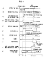
- the cap body 8 is locked to the hopper 3 (at points of time t1 through t2 of A in Fig. 3 and B in Figs. 3 ).
- the detection means 24 is positioned at a lock position of the hopper 3 so that proximity and departure of the cap body 8 can be detected by the detection means 24.
- the control unit 25 generates a lock-detecting signal (on the proximity of the cap body 8) and a lock-releasing signal (on the departure of the cap body 8) based on signals from this detection means 24 (at points of time t2 and t9 of C in Fig. 3 ).
- the crush water open-and-close valve 55 is first controlled so as to be opened on the basis of the control signal from the control unit 25 (at point of time t2 of D in Fig. 3 ) .
- the crush water open-and-close valve 55 is controlled so as to be successively opened during a period of time (Tx) from the point of time t2 to the point of time t7, which will be described later.
- Tx period of time
- the crush water open-and-close valve 55 is opened, the crush water is supplied to the cap body 8 through the water supply port 9, so that the crush water is supplied into the housing 31 through the water-supply ports 13 provided on the bottom of the cap body 8 (see E in Fig. 3 ).
- a predetermined time ⁇ t for example, 15 seconds
- a supply of the rinse water to the S trap pipe 40 is started.
- the rinse water open-and-close valve 57 is controlled so as to be opened so that the rinse water can be supplied (see J in Fig. 3 and K in Fig. 3 ).
- the rinse water is then supplied to a side of the S trap pipe 40 and acts on the crushed particles which are fallen from the bottom plate 22 up to the first branching pipe 41a of the branching pipe 41 through the drain-pipe-connecting port 21.
- the rinse water in this moment assists in falling down the crushed particles, thereby causing the discharging process of the crushed particles to be further smoothly performed.
- the crushed particles are then discharged to a side of the drain pipe 39 through the S trap pipe 40.
- a period of assisting time Td for the discharging process may be set an optional time but, in this embodiment, it is set to time of about 10 seconds so that the assistance for the discharging process can be completed during a period of the crushing-and-discharging process time Tb,
- a crushing-and-discharging process (during a period of time Tc) is continued without any break even after the crushing-and-discharging process (during a period of time Tb) has been completed (see G in Fig. 3 ).
- Tc a crushing-and-discharging process
- Tb a period of time
- the driving motor 6 may stop during the period of crushing-and-discharging process time Tc and only draining process is performed only by supplying water from the crush water open-and-close valve 55 and the like may be selected.
- the driving motor 6 is continuously operated even after the crushing-and-discharging process (a period of time Tb) has been elapsed and the water supply from the crush water open-and-close valve 55 is performed, thereby setting the crushing-and-discharging process (a period of time Tc) (see F in Fig. 3 ). Shift to the discharging process is informed by the buzzer 70 (at a point of time t6 of H in Fig. 3 ).
- any audio assists are performed (at point of time t6 of I in Fig. 3 ).
- a simple message such as "This is the discharging process of crushed particles" is sufficient for the audio assists.
- Both of buzzer sounds and audio assists are not performed but either buzzer sounds or audio assists may be performed.
- the crushing process is almost completed during a period of the crushing-and-discharging process time Tb, but a part of the crushed particles may be left in the housing 31 if the garbage is difficult to be crushed, as described above. Further, a part of the crushed particles may be adhered as they are to an inner wall of the housing 31 and the crushing unit 4 under the crushing process during a period of time Tb. Accordingly, by utilizing a second half of the period of time Tc, sedimentary process and rinsing process are performed at the same time. Therefore, the crush water is supplied even during the second half of the period of time Tc.
- the crushing-and-discharging process goes on if the crushing process has not yet completed for the period of time Tb while process for the sedimentary that is kept on adhering to the inner wall of the housing 31 and the crushing unit 4 and the rinsing process for the inner wall of the housing 31 and the crushing unit 4 can be almost surely performed, if the crushing process has completed, by dispersing the supplied crush water to inside of the housing 31 with the crushing unit 4.
- the crush water open-and-close valve 55 is controlled so as to be closed, thereby stopping the supply of the crush water (see D, E, and G in Fig. 3 ).
- the rinse water open-and-close valve 57 is controlled so as to be opened, thereby supplying the rinse water to the side of the S trap pipe 40 only for some time Te (for example, 5 seconds) from the point of time t7.
- the rinse water is ejected and supplied into the S trap pipe 40 (between points of time t7 and t8 of K in Fig. 3 ), so that the crushed particles left in the S trap pipe 40 can be discharged at once and at the same time, any rinse in the pipe can be done.
- the buzzer 70 sounds again at almost the same time (point of time t7) of the start of this rinsing process, and any audio assists are carried out.
- a simple message such as "The garbage disposal process has finished” is sufficient for the audio assists.
- Such the buzzer sounds and/or audio assists allow even a user who stays in a place away from a kitchen to surely confirm that the garbage disposal process is finished.
- the lock of cap body 8 may be released and the cap body 8 may be detached (at point of time t10 of A in Fig. 3 and B in Fig. 3 ) and then, attached.
- the crushed particles fall down together with the crush water to a side of the bottom plate 22 evenly and are discharged, and the crushed particles are discharged to a side of the drain pipe 39 without being left therein by means of the supply of the rinse water during the crushing process.
- the drain pipe 39 gets stopped by the crushed particles.
- the lock detection signal and the lock release signal are respectively generated in the control unit 25 with them being synchronism with the detection of proximity and departure of the cap body 8 by the detection means 24, as shown in C of Fig. 3 .
- energization to the driving motor 6 starts and based on the lock release signal, the energization to the driving motor 6 ends.
- FIG. 3 An embodiment shown in Fig. 3 is an embodiment where the lock of the cap body 8 is released at a stage (point of time t9) in which all the processes (the crushing and discharging processes) have completed, so that the energization to the driving motor 6 has ended at a point of time before the lock release signal is given.
- the lock release signal is generated in synchronization with the departure of the cap body 8 at this time, as shown in Fig. 4 , so that the energization to the driving motor 6 is forced to end (see B, C, D and F in Fig. 4 ).
- the buzzer sounds and the audio assists are carried out (see H in Fig. 4 and I in Fig. 4 ).
- the audio assists such as "Forced termination of the garbage disposal is made" are done, so that process result when the cap body 8 is operated can be informed.
- cap body 8 When the cap body 8 is again attached and locked, it is returned to its initial state and process shown in Fig.3 starts from its first routine, thereby advancing the crushing and discharging processes.
- an amount of the above-mentioned crush water and rinse water to be supplied is around 8 liter/min. It is not necessary that an amount of the crush water for the previously water-supplying time (time Ta) or an amount of the rinse water discharging-and-rinsing process (time Te) after the discharging process is kept to an amount of their water during crushing-and-discharging process.
- time Ta previously water-supplying time
- time Te rinse water discharging-and-rinsing process
- the crush water open-and-close valve 55 and the rinse water open-and-close valve 57 are controlled so that the amounts of the crush water and the rinse water can become an almost half of them during the crushing-and-discharging process.
- the rinse water may be ejected as it is or as waterjet.
- the garbage disposal apparatus according to this invention is very preferably-applied to a garbage disposal apparatus that is used for a kitchen sink for household use or the like.
Landscapes
- Engineering & Computer Science (AREA)
- Environmental & Geological Engineering (AREA)
- Health & Medical Sciences (AREA)
- Life Sciences & Earth Sciences (AREA)
- Hydrology & Water Resources (AREA)
- Public Health (AREA)
- Water Supply & Treatment (AREA)
- Crushing And Pulverization Processes (AREA)
- Sink And Installation For Waste Water (AREA)
- Cleaning In General (AREA)
- Processing Of Solid Wastes (AREA)
Abstract
Crush water is supplied to a housing in a hopper (3). Rinse water is supplied to a trap pipe (40) that is connected to a discharging outlet of the housing. An ejection water-supplying portion (42) for the rinse water is connected to the trap pipe. The crush water is supplied from just before the crushing process starts. The rinse water to be supplied to the trap pipe is supplied only for a predetermined period of time during crushing process as well as after the crushing process. When the rinse water is supplied to the trap pipe during the crushing process, suction acts thereon such that crushed particles flown down to the discharging outlet of the housing can be pushed out by a stream flown into the trap pipe. An action of such the suction allows the crushed particles to be discharged to a drain pipe side through the trap pipe all around during the crushing process, thereby increasing any discharge effect. The rinse water after the crushing process is supplied after a predetermined period of time has been lapsed from the completion of the crushing process, thereby discharging any particles left in the trap pipe and rinsing the trap pipe.
Description
- The present invention relates to a garbage disposal apparatus which is applicable to kitchen facilities. More specifically, it relates to the one that can prevent any crushed particles from being left in a trap pipe by supplying rinse water not only after crushing process but also during the crushing process, if the rinse water is supplied to the trap pipe which connects to a drain side of the garbage disposal apparatus main body, in addition to a water supply of crush water to the garbage disposal apparatus main body.
- As the garbage disposal apparatus to crush garbage, which is used in general households, restaurants, etc., garbage disposal apparatuses of a hammer mill type and a grinder type have been known.
- The garbage disposal apparatus of hammer mill type has a fixed hammer or a slidable hammer on a disk arranged at a bottom of a cylindrical hopper. Garbage thrown into the hopper has been pressed against an inner circumferential surface of the hopper by centrifugal force that occurs due to a revolution of the disk so that the garbage can be crushed by the hammer. The crushed garbage has then fallen down through grooves formed in a wall surface of the hopper or a gap between an outer edge of the disk and the inner circumferential surface of the hopper. The crushed garbage, which has fallen down, has, then, drained into a side of drain pipe thereof.
- The garbage disposal apparatus of hammer mill type has been designed to drive the disk which installs the hammer for crushing the garbage in the hopper, at high speed of several thousands of revolutions (rpm) so that it produces any hideous noises and/or vibrations because the garbage collides with the hammer and the inner circumferential surface of the hopper so as to be crushed.
- On the other hand, in the garbage disposal apparatus of grinder type, a crushing unit has been used in which a rotary blade and a fixed blade, each having comb-tooth shaped blades, have been laminated alternately. It has been configured so that these rotary blade and fixed blade constituting the crushing unit can be engaged with each other with small spacing held between them, thereby revolving the rotary blade to crush the garbage with the garbage being gripped by the rotary blade and fixed blade. Blades of the laminated rotary blade and fixed blade have finer pitches in proportion to the lower laminated layer. Thus, the garbage thrown into the hopper has first been crushed roughly by the rotary blade and fixed blade of higher layer, has then been crushed finely by the rotary blade and fixed blade of lower layer, and has been discharged downwardly.
- This garbage disposal apparatus of grinder type having such a configuration that these rotary blades and fixed blades are laminated has not required any centrifugal force, thereby allowing it to produce low noise by controlling number of revolutions.
- On any of these garbage disposal apparatuses, tap water used as any processing water for enabling crushed particles of the garbage to fall down may be supplied under automatic control. In this case, the processing water (hereinafter, referred to as "crush water") is automatically supplied into a housing provided in the garbage disposal apparatus main body.
- Further, if the garbage disposal apparatus of this type is disposed with it being installed in a kitchen sink, between the housing and a drain pipe, a trap pipe is generally connected to them. With a view of discharging any crushed particles left in the trap pipe therefrom and rinsing the inside thereof, rinse water may be supplied apart from the crush water.
- However, in the above-mentioned garbage disposal apparatuses, in a case of combining the automatic water-supplying process and the rinsing process of the trap pipe, there has been a problem at what kind of timing the two processes, particularly, the rinsing process, are to be carried out. This is because in some timing of the rinsing process, any crushed particles may not be discharged successfully from the housing or a part of the discharged crushed particles may be left in the trap pipe. The rinse water could be wasted.
- The present invention has thus solved such the conventional problem and has provided a garbage disposal apparatus that can prevent any crushed particles from being left in the trap pipe, when crushing process of the garbage and rinsing process of crushed particles are carried out using the rinse water in addition to the crush water, by particularly making the rinse water supply timing not only after the crushing process but also during the crushing process.
- A garbage disposal apparatus according to the invention characterized in that the apparatus comprises:
- a garbage disposal apparatus main body that is installed under a drain opening of a kitchen sink;
- a housing that is configured so as to be attached into or detached from the garbage disposal apparatus main body and in which a crushing unit is installed;
- a crush water open-and-close valve for supplying crush water to the housing, which is provided at a water-supply opening side of the housing;
- a trap pipe that is connected to the housing;
- a rinse water open-and-close valve for supplying rinse water to the trap pipe, which is connected to the trap pipe; and
- a control means for controlling the crush water open-and-close valve and the rinse water open-and-close valve,
- According to the present invention, by supplying the rinse water to the trap pipe during the crushing process, it is possible to increase any discharge effect on the crushed particles and to prevent the crushed particles from being left in the trap pipe. Further, at the same time, it is possible to rinse inside of the trap pipe by a stream of water flown into the trap pipe.
-
- [
FIG. 1 ] is a conception diagram for showing one embodiment of a garbage disposal apparatus according to the present invention. - [
FIG. 2 ] is a sectional view of an important portion of the garbage disposal apparatus, to which the present invention is applicable, for illustrating one example thereof. - [
FIG. 3 ] is a timing chart (part one) for showing a processing example of the garbage disposal apparatus according to the present invention; and - [
FIG. 4 ] is a timing chart (part two) for showing a processing example of the garbage disposal apparatus according to the present invention. - The following will describe a case where a garbage disposal apparatus according to the invention is applied to a tap water supply system for a garbage disposal apparatus that is installed in a kitchen sink.
-
FIG. 1 shows a conception diagram of a case where this invention is applied to a tap water supply system for thegarbage disposal apparatus 1 that is installed in a kitchen sink for household use. - The
garbage disposal apparatus 1 is fixed on and installed in a drain opening So provided in almost middle of a bottom of a kitchen sink S on its rear side of the bottom. Thegarbage disposal apparatus 1, which will be described later, has atubular hopper 3 in which a crushing unit is provided. The crushing unit is rotatably driven by amotor 6. - As the crushing unit, the above-mentioned hammer mill typed one that crushes the garbage using a hammer mill, the grinder typed one that crushes the garbage using rotary blade and fixed blade, and the like can be used. The following embodiments relate to the garbage disposal apparatus using the latter (grinder type).
- As shown in
FIG. 1 , to an upper circumferential surface of thehopper 3, asupply port 9 for the tap water and a connectingpipe 10 that is connected to thissupply port 9 are respectively connected. On a lower circumferential surface of thehopper 3, a drain-pipe-connectingport 21 is provided, and through this drain-pipe-connectingport 21, the crushed garbage, crush water (water for allowing the crushed particles to flow downward) used when crushing it and the like are discharged to adrain pipe 39. - Well-known trap pipe, for example,
S trap pipe 40, is connected to the drain-pipe-connectingport 21 and thedrain pipe 39. In this embodiment, between theS trap pipe 40 and the drain-pipe-connectingport 21, a branchingpipe 41 is provided. The branchingpipe 41 has around T-shape and a first branchingpipe 41a is connected to the above-mentionedS trap pipe 40 as well as at a side of a second branchingpipe 41b that is connected to theS trap pipe 40 on a vertical line, an ejection water-supplyingportion 42 acting as ejection water-supplying means of the rinse water is connected. This ejection water-supplyingportion 42 is provided for preventing any crushed particles from being left in theS trap pipe 40 and supplies the rinse water to theS trap pipe 40 to discharge the particles left in the pipe and to rinse inside of the trap pipe. - In the embodiment of
FIG. 1 , as the kitchen sink S, a sink in which astep portion 50 is provided at a one level lower hollowed portion than an upper flat surface (overflow edge) Sa is used. Atap 51 is mounted and fixed on thestep portion 50 so that it can stand projecting thereon. By controlling ahandle 52 of thetap 51, open and close (stop) of the tap for tap water is carried out. -
Vacuum breaker 60 for the tap water to be supplied to thegarbage disposal apparatus 1 is also provided on thestep portion 50. Thevacuum breaker 60 is provided for preventing the tap water and water (dirty water) at a side of thegarbage disposal apparatus 1 from being directly mixed, and the tap water is once conducted to thevacuum breaker 60 and the tap water ejected from thevacuum breaker 60 is then conducted to thegarbage disposal apparatus 1 and theS trap pipe 40. - Therefore, as the
vacuum breaker 60, duplex one is used. A first branching pipe 53a branched from a water main 53 is connected to thetap 51. Second and third branchingpipes vacuum breaker 60. - A crush water open-and-
close valve 55 and a rinse water open-and-close valve 57 are disposed on the second and third branchingpipes close valve 55 and the rinse water open-and-close valve 57, for example, any electromagnetic valves are used. Awater pipe 54 is connected to an ejection port relating to the second branchingpipe 53b and the connectingpipe 10. It can be connected direct to thesupply port 9 for the tap water, not through the connectingpipe 10. - Connecting such the water pipes and the like allows processed water (the crush water and the rinse water) to be supplied to sides of the
supply port 9 for the tap water and thedrain port 21 of thegarbage disposal apparatus 1 through thevacuum breaker 60 following their separate courses. - As the
vacuum breaker 60, an air-open type one (atmospheric one) is used. Even if any negative pressure bringing a dirty water level to rise based on a water cutoff or the like acts on a side of the drain pipe, thisvacuum breaker 60 can separate any tap water system from the dirty water system surely. -
FIG. 2 shows an embodiment of thegarbage disposal apparatus 1, to which the present invention is applicable. Thisgarbage disposal apparatus 1 has thehopper 3. Thehopper 3 into which any garbage and the like are thrown is mounted on abase frame 2 and an upper edge of thehopper 3 is fit into the drain opening So of the kitchen sink S. - Inside of the
hopper 3, the crushingunit 4 is installed so as to be detachably from thehopper 3. In the crushingunit 4, a crushing rotary blade, which will be described later, is fit to a driving shaft 5a of areduction unit 5 and themotor 6 installed in the base frame rotatively drives the crushing rotary blade of the crushingunit 4 through thereduction unit 5. A portion of the driving shaft 5a, which transmits any driving force to the crushingunit 4, the portion being fitted to the crushingunit 4, is formed so as to be square shaft like one, spline shaft like one or the like. - The
hopper 3 is provided with a throwing opening portion 7 at its upper end and acap body 8 is placed into the throwing opening portion 7 so as to be detachable or attachable. The throwing opening portion 7 is provided with the above-mentionedsupply port 9. The tap water is supplied to thecap body 8 through thesupply port 9 and then, supplied from thecap body 8 into thehopper 3, which is used as the crush water. - The
cap body 8 is provided with an inner cap 8a and an upper cap 8b. The inner cap 8a has an opening at its upper portion and a cylinder shape with a bottom at its lower portion, so that a water-impingingportion 12 can be formed as to be projected from a bottom portion 11 and a plurality of water-supply ports 13 can be formed around the water-impingingportion 12. The water- impingingportion 12 and the water-supply ports 13 constitute water storage portion 11a. - The water-supply ports 13 are formed all over the bottom portion 11 of the water storage portion 11a with them extending from an inner circumferential side thereof to an outer circumferential side thereof. The water-supply ports 13 may be arranged, for example, in a radial manner.
- The water storage portion 11a has a
supply port 18 penetrating through a side portion of the inner cap 8a from its outer circumferential surface to its inner circumferential surface. Therefore, if thecap body 8 is fit into the throwing opening portion 7, thesupply port 18 is formed so as to communicate with thesupply port 9 of thehopper 3. - The water-impinging
portion 12 is configured so that a surface of its wall which stands from the bottom portion 11 can be formed at an opposite position to thesupply port 18. The water-impingingportion 12 is disposed at a generally right angle to a water-discharging direction from thesupply port 18 in its horizontal direction. A slant surface that is inclined towards a direction where its upper portion is positioned at an inner side is also formed in its vertical direction. This is because the water supplied into thecap body 8 is dispersed all over around it and fallen into thehopper 3. - Inside the
hopper 3, abottom plate 22 that is inclined towards the drain-pipe-connectingport 21 and an opening 22a, through which the driving shaft 5a of thereduction unit 5 is passed, is formed at a center of thebottom plate 22. - In this embodiment, by rotating the
cap body 8 to a predetermined direction only by a predetermined angle with thecap body 8 being placed in the throwing opening portion 7, thecap body 8 achieves a locked state thereof. When achieving the locked state thereof, thecap body 8 is locked into thehopper 3. Thegarbage disposal apparatus 1 starts its operation state while thecap body 8 is locked. Such the locked state of thecap body 8 is detected by detection means 24 which is attached to an outer circumferential surface of thehopper 3. As the detection means 24, a magnetic sensor (proximity sensor) and the like are used so that magnet, not shown, is fit or fixed to a corresponding position in thecap body 8. - The
garbage disposal apparatus 1 is provided with a control unit 25 (control means including CPU) that controls rotation driving of themotor 6. Thecontrol unit 25 controls the crush water open-and-close valve 55 and the rinse water open-and-close valve 57 to open or close, themotor 6 to start or stop, and the like, in response to any detection signals from the detection means 24, any control signals generated on the basis of internal clock, and the like. Abuzzer 70 and/or aspeaker 72 are/is driven in response to the open/close control of the crush water open-and-close valve 55 and the rinse water open-and-close valve 57 and it is so configured that any information of the course of crushing process by any buzzer sounds and any audio assists are performed under a control from thecontrol unit 25. - As the crushing
unit 4 installed in thehousing 31, a crushing blade closely resemble to a configuration disclosed in Japanese Patent Application Publication No.2004-29880 unit 4 is used as a unit in which a first crushingrotary blade 26, a second crushing fixedblade 27, a thirdcrushing rotary blade 28, a fourth crushing fixedblade 29, and a fifth crushingrotary blade 30 are laminated. - The
housing 31 has a cylinder shape and it is so configured that an outer diameter thereof is almost the same as an inner diameter of thehopper 3. The crushingunit 4 is installed into thehopper 3 from a side of the throwing opening portion 7 thereof. Thehousing 31 is provided with a handle 31c for attaching and detaching, which is constituted of a metal rod having a circular shape. The handle 31c is fit to an upper side of thehousing 31 with it extending along its diameter direction. - The first crushing
rotary blade 26 is constituted of one stirring arm that extends horizontally from one side of a side portion of a bearing portion 32. - The second crushing fixed
blade 27 has two plate-like arms which extend horizontally with 180 degrees angle to each other and their edges formed on both side surfaces thereof act as crushing blades. - The third
crushing rotary blade 28 has three arms which extend from its center in a radial manner with 120 degrees angle to each other. In each of the arms, a comb-tooth section is formed with a predetermined pitch on their bottom side. - The fourth crushing fixed
blade 29 has a shape such that eight arms extending radially from a center thereof in a tangential direction at regular intervals are encircled by a ring. On each of, for example, the six arms out of the eight arms thereof, a comb-tooth section that is mesh with the third crushingrotary blade 28 is formed on their upper surface and they mesh with the third crushingrotary blade 28. The comb-tooth section of the fourth crushing fixedblade 29 crushes the garbage sent out of the upper row crushing blades in co-operation with the comb-tooth section of the third crushingrotary blade 28. - On an outer circumference of the ring, tabs 29a projecting in a radial direction with 180 degree angle to each other are formed. The tabs 29a are respectively fit into vertical grooves 31b of the
housing 31, thereby limiting the rotation of the fourth crushing fixedblade 29. - The fifth crushing
rotary blade 30 has a disk shape and it is configured so that a plurality of slits is arranged over the entire thereof except for a center hub. In this embodiment, they are constituted of plural slit groups, and adjacent slit groups are disposed in nearly parallel with each other. - An upper surface of the fifth crushing
rotary blade 30 is plane and rotates with it being connected with a bottom surface of each of the arms of the fourth crushing fixedblade 29. Further, the slits pierce through the fifth crushingrotary blade 30 from its front to its back so that sharp edges can be formed on their upper open edges of the slits. Therefore, the garbage, which is crushed with the comb-tooth section of the third crushingrotary blade 28 and the comb-tooth section of the fourth crushing fixedblade 29 and fallen down to the upper surface of the fifth crushingrotary blade 30, is caught by the slits, and then, by rotating the fifth crushingrotary blade 30, it is pushed against the slits and further crushed by the edge parts of the slits. The finely crushed garbage is fallen down together with the crush water passing through the slits, is passed onto thebottom plate 22 of thehopper 3, and is discharged through the drain-pipe-connectingport 21 to outside. - The crush water open-and-
close valve 55 and the rinse water open-and-close valve 57 are respectively controlled in response to the open/close operation of thecap body 8 so that any supply control on the crush water and the rinse water can be performed. Such the supply control on the water relates to any controls on the crush water into thehousing 31 and the rinse water to theS trap pipe 40. Thecontrol unit 25 carries out such the supply control based on the detection signals from the detection means 24 and the like. It is assumed that thecontrol unit 25 contains any timer functions (any counter functions). - The following will describe an embodiment of the water-supply control with reference to
Fig. 3 . When the crushing process is being performed, discharging process of the crushed particles is also performed at the same time. Crushing and discharging process time when such the crushing process and the discharging process coincidently advance is set to Tb. A case where the crushing-and-discharging process is successively performed during predetermined time Tc even after the crushing process has completed, in order to increase any crushing effects, is illustrated. These process time and predetermined time may be expressed as a period of process time or a predetermined period of time, for purpose of description. - In this embodiment, pieces of the crushing-and-discharging process time Tb, Tc are set to almost the same time. This is because if these pieces of the process time Tb, Tc are set so as to be too short, the crushing process and the discharging process are insufficient while if they are set so a to be too long, the process time or power is wasted. Based on various kinds of experiments, it was clear that about 30 through 40 seconds were preferable for the process time Tb, Tc, and a total of about 60 through 70 seconds were preferable.
- of course, it is possible to set the crushing-and-discharging process time Tb longer and the successive crushing-and-discharging process time Tc shorter so as to set the total of process time to be made equal. For example, if the total of process time is set to 60 seconds (Tb+Tc=60 seconds), it follows that Tb is set to 40 (Tb=40 seconds) and Tc is set to 20 (TC=20 seconds). In illustration of
FIG. 3 , a case where Tb is set to 30 (Tb=30 seconds) and Tc is set to 30 (TC=30 seconds) is shown. The illustration will be made with reference toFig. 3 . - In a step where the garbage is thrown into the
housing 31, thecap body 8 is attached to the opening portion 7. By rotating thecap body 8 to a predetermined direction only by a predetermined angle after attaching it, thecap body 8 is locked to the hopper 3 (at points of time t1 through t2 of A inFig. 3 and B inFigs. 3 ). The detection means 24 is positioned at a lock position of thehopper 3 so that proximity and departure of thecap body 8 can be detected by the detection means 24. - The
control unit 25 generates a lock-detecting signal (on the proximity of the cap body 8) and a lock-releasing signal (on the departure of the cap body 8) based on signals from this detection means 24 (at points of time t2 and t9 of C inFig. 3 ). - If generating the lock-detecting signal, the crush water open-and-
close valve 55 is first controlled so as to be opened on the basis of the control signal from the control unit 25 (at point of time t2 of D inFig. 3 ) . The crush water open-and-close valve 55 is controlled so as to be successively opened during a period of time (Tx) from the point of time t2 to the point of time t7, which will be described later. When the crush water open-and-close valve 55 is opened, the crush water is supplied to thecap body 8 through thewater supply port 9, so that the crush water is supplied into thehousing 31 through the water-supply ports 13 provided on the bottom of the cap body 8 (see E inFig. 3 ). - Since it is because surfaces of an inner wall of the
housing 31 and a surface of the crushingunit 4 are easily wetted by the crush water to supply the water previously only by predetermined time Ta just before the crushing process starts, this may prevent the garbage from being adhered to these parts when the successive crushing process is performed. Thus, as the time Ta for the previous water supply, about 5 seconds may be set. - When this previous water supply time has elapsed, regular crushing process is carried out while the water supply is maintained (after a point of time t3 of G in
Fig. 3 ). Therefore, the drivingmotor 6 is turned on starting from point of time t3 so that the crushingrotary blades unit 4 can be rotatively driven (see F inFig. 3 ). By cooperating the crushing rotary blades and the crushing fixed blades, the crushing process on the garbage advances. Since the crush water is supplied during the crushing-and-discharging process (a period of time Tb) when the crushing process and the discharging process are performed at the same time, the garbage is easy to be further crushed by the crush water, thereby increasing the advance of the crushing process. - The crush is not enough advanced just after the crushing-and-discharging process starts, so that the crushed particles has been yet failed to fall to a side of the
bottom plate 22 below the fifth crushingrotary blade 30. It was confirmed by the experiment that when the garbage was finely crushed to some extent, the finely crushed particles started falling to a side of thebottom plate 22 below the fifth crushingrotary blade 30. Therefore, during a first half of the period of crushing-and-discharging process time Tb (converted in time of about 10 through 15 seconds after the crush starts), only the crushing process is mostly performed and then, an almost certain amount of the crushed particles is gradually fallen into the side of thebottom plate 22 and discharged. - Thus, in this embodiment, starting from a point of time t4 when a predetermined time Δt (for example, 15 seconds) has been elapsed after the crushing starts, it is shifted to a process for assisting the discharging process of the crushed particles. Namely, a supply of the rinse water to the
S trap pipe 40 is started. Accordingly, the rinse water open-and-close valve 57 is controlled so as to be opened so that the rinse water can be supplied (see J inFig. 3 and K inFig. 3 ). - As a result thereof, the rinse water is then supplied to a side of the
S trap pipe 40 and acts on the crushed particles which are fallen from thebottom plate 22 up to the first branchingpipe 41a of the branchingpipe 41 through the drain-pipe-connectingport 21. The rinse water in this moment assists in falling down the crushed particles, thereby causing the discharging process of the crushed particles to be further smoothly performed. The crushed particles are then discharged to a side of thedrain pipe 39 through theS trap pipe 40. - A period of assisting time Td for the discharging process may be set an optional time but, in this embodiment, it is set to time of about 10 seconds so that the assistance for the discharging process can be completed during a period of the crushing-and-discharging process time Tb,
- A crushing-and-discharging process (during a period of time Tc) is continued without any break even after the crushing-and-discharging process (during a period of time Tb) has been completed (see G in
Fig. 3 ). Based on various kinds of experiments, it is clear that general crushing itself of the garbage thrown into inside of thehopper 3 has almost completed during a period of the crushing-and-discharging process time Tb. Accordingly, a distance where the drivingmotor 6 may stop during the period of crushing-and-discharging process time Tc and only draining process is performed only by supplying water from the crush water open-and-close valve 55 and the like may be selected. - Herein, by taking into consideration an assumption of a case where a large amount of the garbage that is difficult to be crushed such as fiber-rich particles or bone and shell is thrown as the garbage and all the crushes have been not yet completed during the crushing-and-discharging process (a period of time Tb), the driving
motor 6 is continuously operated even after the crushing-and-discharging process (a period of time Tb) has been elapsed and the water supply from the crush water open-and-close valve 55 is performed, thereby setting the crushing-and-discharging process (a period of time Tc) (see F inFig. 3 ). Shift to the discharging process is informed by the buzzer 70 (at a point of time t6 of H inFig. 3 ). In this embodiment, at the same time, any audio assists are performed (at point of time t6 of I inFig. 3 ). A simple message such as "This is the discharging process of crushed particles" is sufficient for the audio assists. Both of buzzer sounds and audio assists are not performed but either buzzer sounds or audio assists may be performed. - The crushing process is almost completed during a period of the crushing-and-discharging process time Tb, but a part of the crushed particles may be left in the
housing 31 if the garbage is difficult to be crushed, as described above. Further, a part of the crushed particles may be adhered as they are to an inner wall of thehousing 31 and the crushingunit 4 under the crushing process during a period of time Tb. Accordingly, by utilizing a second half of the period of time Tc, sedimentary process and rinsing process are performed at the same time. Therefore, the crush water is supplied even during the second half of the period of time Tc. - During the second half of the period of the crushing-and-discharging process time Tc, the crushing-and-discharging process goes on if the crushing process has not yet completed for the period of time Tb while process for the sedimentary that is kept on adhering to the inner wall of the
housing 31 and the crushingunit 4 and the rinsing process for the inner wall of thehousing 31 and the crushingunit 4 can be almost surely performed, if the crushing process has completed, by dispersing the supplied crush water to inside of thehousing 31 with the crushingunit 4. - At a point of time t7 when the period of the crushing-and-discharging process time Tc expires, the crush water open-and-
close valve 55 is controlled so as to be closed, thereby stopping the supply of the crush water (see D, E, and G inFig. 3 ). At the same time thereof, the rinse water open-and-close valve 57 is controlled so as to be opened, thereby supplying the rinse water to the side of theS trap pipe 40 only for some time Te (for example, 5 seconds) from the point of time t7. The rinse water is ejected and supplied into the S trap pipe 40 (between points of time t7 and t8 of K inFig. 3 ), so that the crushed particles left in theS trap pipe 40 can be discharged at once and at the same time, any rinse in the pipe can be done. - The
buzzer 70 sounds again at almost the same time (point of time t7) of the start of this rinsing process, and any audio assists are carried out. A simple message such as "The garbage disposal process has finished" is sufficient for the audio assists. Such the buzzer sounds and/or audio assists allow even a user who stays in a place away from a kitchen to surely confirm that the garbage disposal process is finished. - If the
garbage disposal apparatus 1 is again used, at a point of optional time t9 thereafter, the lock ofcap body 8 may be released and thecap body 8 may be detached (at point of time t10 of A inFig. 3 and B inFig. 3 ) and then, attached. - Thus, during the crushing process, the crushed particles fall down together with the crush water to a side of the
bottom plate 22 evenly and are discharged, and the crushed particles are discharged to a side of thedrain pipe 39 without being left therein by means of the supply of the rinse water during the crushing process. Thus, by the even discharge of the crushed particles, there is no danger such that thedrain pipe 39 gets stopped by the crushed particles. - The lock detection signal and the lock release signal, however, are respectively generated in the
control unit 25 with them being synchronism with the detection of proximity and departure of thecap body 8 by the detection means 24, as shown in C ofFig. 3 . Based on the lock detection signal, energization to the drivingmotor 6 starts and based on the lock release signal, the energization to the drivingmotor 6 ends. - An embodiment shown in
Fig. 3 is an embodiment where the lock of thecap body 8 is released at a stage (point of time t9) in which all the processes (the crushing and discharging processes) have completed, so that the energization to the drivingmotor 6 has ended at a point of time before the lock release signal is given. - If the lock of the
cap body 8 is forced to be released during the energization to the drivingmotor 6, for example, during a period of the crushing-and discharging time Tb when entering into the period of assisting time Td, the lock release signal is generated in synchronization with the departure of thecap body 8 at this time, as shown inFig. 4 , so that the energization to the drivingmotor 6 is forced to end (see B, C, D and F inFig. 4 ). - As a result thereof, even during the crushing-and-discharging process, the crushing-and-discharging process is forced to be finished (see G in
Fig. 4 ). Only the rinse water open-and-close valve 57 is then opened and it is shifted to the discharging process only by the rinse water (see J inFig. 4 and K inFig. 4 ). This is because finely crushed particles, if any, that is a part of the crushed particles can be discharged. - When the garbage disposal is forced to be finished, the buzzer sounds and the audio assists are carried out (see H in
Fig. 4 and I inFig. 4 ). In this case, the audio assists such as "Forced termination of the garbage disposal is made" are done, so that process result when thecap body 8 is operated can be informed. - When the
cap body 8 is again attached and locked, it is returned to its initial state and process shown inFig.3 starts from its first routine, thereby advancing the crushing and discharging processes. - It is preferable that an amount of the above-mentioned crush water and rinse water to be supplied is around 8 liter/min. It is not necessary that an amount of the crush water for the previously water-supplying time (time Ta) or an amount of the rinse water discharging-and-rinsing process (time Te) after the discharging process is kept to an amount of their water during crushing-and-discharging process. Thus, in this embodiment, taking water conservation into consideration, the crush water open-and-
close valve 55 and the rinse water open-and-close valve 57 are controlled so that the amounts of the crush water and the rinse water can become an almost half of them during the crushing-and-discharging process. - It is to be noted that on a supply of the rinse water from the ejection water-supplying
portion 42, the rinse water may be ejected as it is or as waterjet. - The garbage disposal apparatus according to this invention is very preferably-applied to a garbage disposal apparatus that is used for a kitchen sink for household use or the like.
Claims (5)
- A garbage disposal apparatus characterized in that the apparatus comprises:a garbage disposal apparatus main body that is installed under a drain opening of a kitchen sink;a housing that is configured so as to be attached into or detached from the garbage disposal apparatus main body and in which a crushing unit is installed;a crush water open-and-close valve for supplying crush water to the housing, which is provided at a water-supply opening side of said housing;a trap pipe that is connected to said housing;a rinse water open-and-close valve for supplying rinse water to the trap pipe, which is connected to said trap pipe; anda control means for controlling said crush water open-and-close valve and said rinse water open-and-close valve,wherein said rinse water is supplied to said trap pipe during crushing process and after completion of crushing.
- The garbage disposal apparatus according to claim 1, characterized in that the crushing process is controlled in response to a cap body that closes opening of said housing.
- The garbage disposal apparatus according to claim 1, characterized in that said crush water is supplied from just before said crushing process starts.
- The garbage disposal apparatus according to claim 2, characterized in that said crushing process is performed in response to attaching and removing said cap body.
- The garbage disposal apparatus according to claim 1, characterized in that the crush water is supplied successively during the crushing process and the rinse water is supplied only in a part of a period of crushing process time.
Applications Claiming Priority (2)
| Application Number | Priority Date | Filing Date | Title |
|---|---|---|---|
| JP2005363660A JP5282348B2 (en) | 2005-12-16 | 2005-12-16 | Garbage disposal equipment |
| PCT/JP2006/324954 WO2007069691A1 (en) | 2005-12-16 | 2006-12-14 | Garbage treatment device |
Publications (1)
| Publication Number | Publication Date |
|---|---|
| EP1961496A1 true EP1961496A1 (en) | 2008-08-27 |
Family
ID=38162993
Family Applications (1)
| Application Number | Title | Priority Date | Filing Date |
|---|---|---|---|
| EP06834708A Withdrawn EP1961496A1 (en) | 2005-12-16 | 2006-12-14 | Garbage treatment device |
Country Status (3)
| Country | Link |
|---|---|
| EP (1) | EP1961496A1 (en) |
| JP (1) | JP5282348B2 (en) |
| WO (1) | WO2007069691A1 (en) |
Cited By (2)
| Publication number | Priority date | Publication date | Assignee | Title |
|---|---|---|---|---|
| US9145666B2 (en) | 2012-09-12 | 2015-09-29 | Emerson Electric Co. | Magnetically activated switch assembly for food waste disposer |
| US12442166B2 (en) | 2021-05-14 | 2025-10-14 | Kohler Co. | Sink system and components |
Families Citing this family (2)
| Publication number | Priority date | Publication date | Assignee | Title |
|---|---|---|---|---|
| CN108262333A (en) * | 2018-01-10 | 2018-07-10 | 湖北合加环境设备有限公司 | Kitchen waste preprocessing technology and system based on high-pressure extrusion technology |
| CN118268326B (en) * | 2024-05-31 | 2024-07-30 | 唐山冀东装备工程股份有限公司 | Unmanned cement silo cleaning equipment |
Family Cites Families (6)
| Publication number | Priority date | Publication date | Assignee | Title |
|---|---|---|---|---|
| JPH10263430A (en) * | 1997-03-26 | 1998-10-06 | Inax Corp | Raw refuse crushing treatment apparatus |
| JP2001115519A (en) * | 1999-10-21 | 2001-04-24 | Toto Ltd | Garbage disposal system |
| JP2001200564A (en) * | 2000-01-21 | 2001-07-27 | Toto Ltd | Garbage disposal system |
| JP2002336722A (en) * | 2001-05-15 | 2002-11-26 | Shin Meiwa Ind Co Ltd | Garbage processing equipment |
| JP2003024813A (en) * | 2001-07-17 | 2003-01-28 | Inax Corp | Disposer |
| JP2004008942A (en) * | 2002-06-07 | 2004-01-15 | Inax Corp | Lid switch mechanism for disposer |
-
2005
- 2005-12-16 JP JP2005363660A patent/JP5282348B2/en not_active Expired - Lifetime
-
2006
- 2006-12-14 WO PCT/JP2006/324954 patent/WO2007069691A1/en not_active Ceased
- 2006-12-14 EP EP06834708A patent/EP1961496A1/en not_active Withdrawn
Non-Patent Citations (1)
| Title |
|---|
| See references of WO2007069691A1 * |
Cited By (2)
| Publication number | Priority date | Publication date | Assignee | Title |
|---|---|---|---|---|
| US9145666B2 (en) | 2012-09-12 | 2015-09-29 | Emerson Electric Co. | Magnetically activated switch assembly for food waste disposer |
| US12442166B2 (en) | 2021-05-14 | 2025-10-14 | Kohler Co. | Sink system and components |
Also Published As
| Publication number | Publication date |
|---|---|
| JP5282348B2 (en) | 2013-09-04 |
| WO2007069691A1 (en) | 2007-06-21 |
| JP2007160281A (en) | 2007-06-28 |
Similar Documents
| Publication | Publication Date | Title |
|---|---|---|
| US20080060533A1 (en) | Apparatus for Peeling Off | |
| JP2009108674A (en) | Force-feed type toilet equipment | |
| WO2008053965A1 (en) | Circulating garbage disposal apparatus | |
| CN115874689B (en) | Kitchen garbage disposer clogging reminder device and method | |
| JPH11179236A (en) | Separation water discharge device in horizontal centrifuge | |
| WO2008038720A1 (en) | Circulation type fragmenting means and toilet apparatus | |
| TW200539944A (en) | Garbage treatment device | |
| JP2008018417A (en) | Method for washing disposer | |
| JP5282348B2 (en) | Garbage disposal equipment | |
| JP4979071B2 (en) | Disposer operation device | |
| JP2009131739A (en) | Garbage disposer | |
| JP2010227820A (en) | Garbage disposal device | |
| JP2010148585A (en) | Beverage dispenser | |
| JP2007136286A (en) | Garbage disposal equipment | |
| WO2007091674A1 (en) | Sanitary item disposal apparatus | |
| JP2008259933A (en) | Disposer | |
| JP2007105671A (en) | Garbage disposer | |
| JP2011240230A (en) | Operation method of agitator | |
| JP4380436B2 (en) | Garbage disposal equipment | |
| JP4923804B2 (en) | Garbage disposal equipment | |
| JP2007175644A (en) | Lid for garbage treatment device, and garbage treatment device having the same | |
| JP4649891B2 (en) | Garbage disposal equipment | |
| JP4581541B2 (en) | Garbage disposal equipment | |
| JP2007275743A (en) | Disposer apparatus | |
| JP2007160200A (en) | Garbage treatment apparatus |
Legal Events
| Date | Code | Title | Description |
|---|---|---|---|
| PUAI | Public reference made under article 153(3) epc to a published international application that has entered the european phase |
Free format text: ORIGINAL CODE: 0009012 |
|
| 17P | Request for examination filed |
Effective date: 20080610 |
|
| AK | Designated contracting states |
Kind code of ref document: A1 Designated state(s): AT BE BG CH CY CZ DE DK EE ES FI FR GB GR HU IE IS IT LI LT LU LV MC NL PL PT RO SE SI SK TR |
|
| STAA | Information on the status of an ep patent application or granted ep patent |
Free format text: STATUS: THE APPLICATION HAS BEEN WITHDRAWN |
|
| 18W | Application withdrawn |
Effective date: 20091028 |