EP1960683B1 - A service disc brake for a heavy vehicle - Google Patents
A service disc brake for a heavy vehicle Download PDFInfo
- Publication number
- EP1960683B1 EP1960683B1 EP06813038A EP06813038A EP1960683B1 EP 1960683 B1 EP1960683 B1 EP 1960683B1 EP 06813038 A EP06813038 A EP 06813038A EP 06813038 A EP06813038 A EP 06813038A EP 1960683 B1 EP1960683 B1 EP 1960683B1
- Authority
- EP
- European Patent Office
- Prior art keywords
- piston
- brake
- disc
- adjusting
- service
- Prior art date
- Legal status (The legal status is an assumption and is not a legal conclusion. Google has not performed a legal analysis and makes no representation as to the accuracy of the status listed.)
- Not-in-force
Links
Images

Classifications
-
- F—MECHANICAL ENGINEERING; LIGHTING; HEATING; WEAPONS; BLASTING
- F16—ENGINEERING ELEMENTS AND UNITS; GENERAL MEASURES FOR PRODUCING AND MAINTAINING EFFECTIVE FUNCTIONING OF MACHINES OR INSTALLATIONS; THERMAL INSULATION IN GENERAL
- F16D—COUPLINGS FOR TRANSMITTING ROTATION; CLUTCHES; BRAKES
- F16D65/00—Parts or details
- F16D65/38—Slack adjusters
- F16D65/40—Slack adjusters mechanical
- F16D65/52—Slack adjusters mechanical self-acting in one direction for adjusting excessive play
- F16D65/56—Slack adjusters mechanical self-acting in one direction for adjusting excessive play with screw-thread and nut
- F16D65/567—Slack adjusters mechanical self-acting in one direction for adjusting excessive play with screw-thread and nut for mounting on a disc brake
-
- F—MECHANICAL ENGINEERING; LIGHTING; HEATING; WEAPONS; BLASTING
- F16—ENGINEERING ELEMENTS AND UNITS; GENERAL MEASURES FOR PRODUCING AND MAINTAINING EFFECTIVE FUNCTIONING OF MACHINES OR INSTALLATIONS; THERMAL INSULATION IN GENERAL
- F16D—COUPLINGS FOR TRANSMITTING ROTATION; CLUTCHES; BRAKES
- F16D55/00—Brakes with substantially-radial braking surfaces pressed together in axial direction, e.g. disc brakes
- F16D55/02—Brakes with substantially-radial braking surfaces pressed together in axial direction, e.g. disc brakes with axially-movable discs or pads pressed against axially-located rotating members
- F16D55/22—Brakes with substantially-radial braking surfaces pressed together in axial direction, e.g. disc brakes with axially-movable discs or pads pressed against axially-located rotating members by clamping an axially-located rotating disc between movable braking members, e.g. movable brake discs or brake pads
- F16D55/224—Brakes with substantially-radial braking surfaces pressed together in axial direction, e.g. disc brakes with axially-movable discs or pads pressed against axially-located rotating members by clamping an axially-located rotating disc between movable braking members, e.g. movable brake discs or brake pads with a common actuating member for the braking members
- F16D55/225—Brakes with substantially-radial braking surfaces pressed together in axial direction, e.g. disc brakes with axially-movable discs or pads pressed against axially-located rotating members by clamping an axially-located rotating disc between movable braking members, e.g. movable brake discs or brake pads with a common actuating member for the braking members the braking members being brake pads
- F16D55/2255—Brakes with substantially-radial braking surfaces pressed together in axial direction, e.g. disc brakes with axially-movable discs or pads pressed against axially-located rotating members by clamping an axially-located rotating disc between movable braking members, e.g. movable brake discs or brake pads with a common actuating member for the braking members the braking members being brake pads in which the common actuating member is pivoted
-
- F—MECHANICAL ENGINEERING; LIGHTING; HEATING; WEAPONS; BLASTING
- F16—ENGINEERING ELEMENTS AND UNITS; GENERAL MEASURES FOR PRODUCING AND MAINTAINING EFFECTIVE FUNCTIONING OF MACHINES OR INSTALLATIONS; THERMAL INSULATION IN GENERAL
- F16D—COUPLINGS FOR TRANSMITTING ROTATION; CLUTCHES; BRAKES
- F16D65/00—Parts or details
- F16D65/14—Actuating mechanisms for brakes; Means for initiating operation at a predetermined position
- F16D65/16—Actuating mechanisms for brakes; Means for initiating operation at a predetermined position arranged in or on the brake
- F16D65/18—Actuating mechanisms for brakes; Means for initiating operation at a predetermined position arranged in or on the brake adapted for drawing members together, e.g. for disc brakes
-
- F—MECHANICAL ENGINEERING; LIGHTING; HEATING; WEAPONS; BLASTING
- F16—ENGINEERING ELEMENTS AND UNITS; GENERAL MEASURES FOR PRODUCING AND MAINTAINING EFFECTIVE FUNCTIONING OF MACHINES OR INSTALLATIONS; THERMAL INSULATION IN GENERAL
- F16D—COUPLINGS FOR TRANSMITTING ROTATION; CLUTCHES; BRAKES
- F16D2121/00—Type of actuator operation force
- F16D2121/02—Fluid pressure
-
- F—MECHANICAL ENGINEERING; LIGHTING; HEATING; WEAPONS; BLASTING
- F16—ENGINEERING ELEMENTS AND UNITS; GENERAL MEASURES FOR PRODUCING AND MAINTAINING EFFECTIVE FUNCTIONING OF MACHINES OR INSTALLATIONS; THERMAL INSULATION IN GENERAL
- F16D—COUPLINGS FOR TRANSMITTING ROTATION; CLUTCHES; BRAKES
- F16D2121/00—Type of actuator operation force
- F16D2121/14—Mechanical
-
- F—MECHANICAL ENGINEERING; LIGHTING; HEATING; WEAPONS; BLASTING
- F16—ENGINEERING ELEMENTS AND UNITS; GENERAL MEASURES FOR PRODUCING AND MAINTAINING EFFECTIVE FUNCTIONING OF MACHINES OR INSTALLATIONS; THERMAL INSULATION IN GENERAL
- F16D—COUPLINGS FOR TRANSMITTING ROTATION; CLUTCHES; BRAKES
- F16D2123/00—Multiple operation forces
-
- F—MECHANICAL ENGINEERING; LIGHTING; HEATING; WEAPONS; BLASTING
- F16—ENGINEERING ELEMENTS AND UNITS; GENERAL MEASURES FOR PRODUCING AND MAINTAINING EFFECTIVE FUNCTIONING OF MACHINES OR INSTALLATIONS; THERMAL INSULATION IN GENERAL
- F16D—COUPLINGS FOR TRANSMITTING ROTATION; CLUTCHES; BRAKES
- F16D2125/00—Components of actuators
- F16D2125/18—Mechanical mechanisms
- F16D2125/20—Mechanical mechanisms converting rotation to linear movement or vice versa
- F16D2125/22—Mechanical mechanisms converting rotation to linear movement or vice versa acting transversely to the axis of rotation
- F16D2125/28—Cams; Levers with cams
- F16D2125/32—Cams; Levers with cams acting on one cam follower
Definitions
- the invention relates to a service disc brake for a heavy vehicle according to the preamble of claim 1.
- the invention is applicable on different type of vehicles. Although the invention is primarily described in connection with trucks, the service disc brake according to the invention can also be used for example in other heavy vehicles such as buses, wheel loaders, articulated haulers, and excavators.
- service disc brakes having a fixed brake caliper can be designed with either a sliding brake disc or a bending brake disc so as to obtain a even clamp force distribution and the requisite running clearance between the brake pads and the brake disc.
- both a bending disc and a sliding disc have large disadvantages.
- a bending disc involves undesired internal stress in the brake disc and in other brake components connected thereto. This in turn can cause damage to the brake.
- a sliding disc results in a more complicated brake design and is further less reliable due to potential jamming caused by corrosion or dirt.
- An object of the invention is to provide a service disc brake of the kind referred to in the introduction where at least some of the problems of such prior art devices discussed above is reduced to a substantial extent.
- both first and second pistons can be displaced and, thus, both first and second pads can be brought into contact with the brake disc without the need of displacing or bending the brake disc.
- a counterforce is created on the third piston which force is transmitted to the second piston by means of the hydraulic fluid and further to the second pad and the brake disc.
- the clamp force can be evenly distributed on the pads arranged on different sides of the brake disc.
- the service disc brake according to the invention is also very suitable to be provided with means for adjusting the running clearances so as to compensate for wear of the pads.
- the invention enables the disc brake to be designed for adjustment of the axial clearance on both sides of the brake disc by operation of one adjustment means only.
- the invention relates also to a vehicle comprising a service disc brake according to the invention.
- a service disc brake 1 according to the invention is illustrated.
- Such a service brake is used for retardation of a vehicle during normal operation of the vehicle, i.e. during driving of the vehicle.
- the service brake is preferably arranged at one or more wheels of the vehicle to brake the wheels.
- the service disc brake 1 comprises a brake disc 2 which is arranged for rotational motion relative to a brake caliper 3 provided with a first brake pad 4 and a second brake pad 5.
- the first and second brake pads are 4, 5 arranged on opposite sides of the brake disc to be brought into contact with the brake disc and thus brake the rotational motion of the disc.
- a first displaceable piston 6 and a second displaceable piston 7 are arranged in the caliper 3 to act on the first brake pad 4 and the second brake pad 5, respectively, so as to bring the pads 4, 5 into contact with the brake disc 2 and transmit the requisite brake force.
- Each piston 6, 7 is displaceable to and fro in the axial direction along a geometrical line 8, and preferably the first and second pistons 6, 7 are displaceable along the same geometrical line 8.
- two or more of the first and second pistons could be used on each side of the brake disc.
- the service disc brake 1 further comprises a third displaceable piston 9.
- the third piston 9 is suitably arranged, for example in the caliper 3, for displacement motions to and fro in the axial direction along for example the same geometrical line 8 as the first piston 6.
- the second piston 7 and the third piston 9 are connected to each other via a closed space 10 containing a hydraulic fluid.
- the term hydraulic fluid is meant to comprise different liquid state fluids.
- the hydraulic fluid is preferably any hydraulic oil, silicon oil or any other suitable high temperature oil.
- the closed space 10 can be constituted by a hydraulic line 11 arranged inside the brake structure or as a piping 11 arranged outside the brake structure. Due to the risk for heating the hydraulic fluid, the closed space 10 is preferably arranged in a well ventilated part of the brake 1.
- a heat shield (not illustrated) may be required to protect the fluid to be heated by hot brake components or other adjacent components.
- the braking actuator 12 may comprise a pivotable lever 13 arranged between the first piston 6 and the third 9 piston.
- the lever 13 may have a first portion 14 for creating a force on the first piston 6 and a second portion 15 for creating a corresponding counterforce on the third piston 9 during pivot motion of the lever 13.
- the lever 13 can be actuated for example by an air cylinder 16 or an electric motor.
- the force applied on the first piston 6 generates an equally sized counterforce on the third piston 9.
- the requisite force can be transmitted from a motor or an air cylinder to the pistons 6, 9 by means of another equipment, such as a wedge or similar, instead of using the lever 13.
- the size of the force on the second piston 7 can be the same as on the first 6 and third 9 pistons provided that the same size of the end surface exposed to the hydraulic fluid is chosen for the second and third pistons.
- the size of the end surface 17 of the third piston 9 is substantially equal to the size of the end surface 18 of the second piston 7.
- the end surfaces 17, 18 can be slightly different for fine adjustment of the brake.
- the service disc brake 1 comprises a first means 19 for adjusting a first axial clearance 20 between the brake disc 2 and the first pad 4.
- the first adjustment means 19 preferably comprise a screw mechanism 21 arranged on the first piston 6.
- a screw mechanism 21 By such a screw mechanism 21 the position of the first piston 6 relative to the brake disc 2 can be adjusted so as to compensate for wear of the first pad 4 and thereby keep the running clearance 20 substantially unchanged.
- the distance from the rear surface 22 cooperating with the first portion 14 of the lever 13 to the front surface 23 of the piston 6, i.e. the total length of the piston 6, can be varied.
- the disc brake 1 comprises also a second means 24 for adjusting a second axial clearance 25 between the brake disc 2 and the second pad 5 by adjusting the position of the second piston 7 relative to the brake disc 2.
- the second adjustment means 24 comprises a fourth displaceable piston 25 which is connected to the second 7 and third 9 pistons via the closed space 10 containing the hydraulic fluid.
- the second adjustment means 24 further comprises a member 26, such as a screw mechanism arranged on the fourth piston 25, for adjusting the position of the second piston 7 by adjusting the position of the fourth piston 25 relative to the closed space 10.
- the position of the second piston 7 can be adjusted so as to compensate for wear of the second pad 5 and thereby keep the running clearance 25 substantially unchanged.
- Each of the first and second pistons 6, 7 can be designed with a total compensation displacement length for example in the size of 20 mm, and the stroke length (axial clearance) can be in the size of 2 mm.
- the fourth piston is not needed and instead the second adjustment means 24b comprises a member 26b, such as a screw mechanism arranged on the third piston 9, for adjusting the position of the second piston 7 by adjusting the position of the third piston 9 relative to the closed space 10.
- the adjusting member 26b is provided with a counter portion 27 of the third piston 9, which counter portion 27 cooperates with the second portion 15 of the lever 13.
- first adjustment means 19 and the second adjustment means 24, 24b can be coupled to each other in order to automatically adjust the second axial clearance 25 at the same time as the first axial clearance 20 is adjusted or vice versa.
- FIG 1 where the screw mechanism arranged on the first piston 6 has a first gear wheel 28 connected to a second gear wheel 29 of the screw mechanism arranged 26 on the fourth piston 25.
- first gear wheel 28 (viewed in a direction from the third piston towards the first piston) is rotated counter clockwise
- the second gear wheel 29 (viewed in the opposite direction) is also rotated counter clockwise.
- both the first piston 6 and the second piston 7 will be displaced towards the brake disc 2.
- the adjustment of the running clearance 20, 25 can be automatically or manually performed with the use of a further mechanical device and/or electrical device (not illustrated) for activation of the first adjustment means 19 and/or the second adjustment means 24, 24b.
- a further mechanical device and/or electrical device for activation of the first adjustment means 19 and/or the second adjustment means 24, 24b.
- any kind of pad wear sensing equipment is preferably used together with the adjustment means described herein.
Abstract
Description
- The invention relates to a service disc brake for a heavy vehicle according to the preamble of claim 1.
- The invention is applicable on different type of vehicles. Although the invention is primarily described in connection with trucks, the service disc brake according to the invention can also be used for example in other heavy vehicles such as buses, wheel loaders, articulated haulers, and excavators.
- In service disc brakes for trucks which brakes have a brake disc and inner and outer brake pads, an even clamp force distribution on the inner and outer pads and a running clearance between the pads and the brake disc are desired. In order to avoid the pads from dragging and leaning against the brake disc there must be a certain axial clearance between the pads and the brake disc when the brake force is removed and the brake disc is not to be braked. Furthermore, the running clearance must be present on the both sides of the brake disc. In trucks, the service disc brake can have a fixed brake caliper and the brake force can be created on one side of the brake disc. Thus, such a service disc brake needs some arrangement for distributing the forces evenly on both the inner and outer pads and for ensuring the running clearance to be present.
- According to prior art, service disc brakes having a fixed brake caliper can be designed with either a sliding brake disc or a bending brake disc so as to obtain a even clamp force distribution and the requisite running clearance between the brake pads and the brake disc. However, both a bending disc and a sliding disc have large disadvantages. A bending disc involves undesired internal stress in the brake disc and in other brake components connected thereto. This in turn can cause damage to the brake. A sliding disc results in a more complicated brake design and is further less reliable due to potential jamming caused by corrosion or dirt. Furthermore, there is a risk a rattling noise arises in the brake. The noise is caused by the requisite radial play between the brake disc and the component arranged to support the brake disc. Wear or inadequate dimensional tolerance distribution of the brake disc and the support component can increase the rattling noise.
- An object of the invention is to provide a service disc brake of the kind referred to in the introduction where at least some of the problems of such prior art devices discussed above is reduced to a substantial extent.
- The object is achieved by a service brake according to claim 1.
- By the provision of a third piston and the closed space containing a hydraulic fluid, which space connects the second and third pistons, both first and second pistons can be displaced and, thus, both first and second pads can be brought into contact with the brake disc without the need of displacing or bending the brake disc. When applying a brake force on the first pad by means of the braking actuator, a counterforce is created on the third piston which force is transmitted to the second piston by means of the hydraulic fluid and further to the second pad and the brake disc. Hence, during braking, the clamp force can be evenly distributed on the pads arranged on different sides of the brake disc. Once the brake force is removed the first and second pads will centre equally relative to the brake disc with substantially the same running clearance on both sides of the brake disc between the brake disc and the first and second brake pads.
- The service disc brake according to the invention is also very suitable to be provided with means for adjusting the running clearances so as to compensate for wear of the pads. The invention enables the disc brake to be designed for adjustment of the axial clearance on both sides of the brake disc by operation of one adjustment means only.
- The invention relates also to a vehicle comprising a service disc brake according to the invention.
- Further advantages and advantageous features of the invention are disclosed in the following description and in the dependent claims.
- With reference to the appended drawings, below follows a more detailed description of embodiments of the invention cited as examples.
- In the drawings:
-
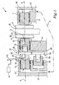
Fig. 1 is a schematic illustration of a disc brake according to the invention, and -
Fig. 2 is a schematic illustration of a variant of the disc brake infigure 1 . - In
figure 1 a service disc brake 1 according to the invention is illustrated. Such a service brake is used for retardation of a vehicle during normal operation of the vehicle, i.e. during driving of the vehicle. By use of the service brake the velocity of the vehicle can be decreased. The service brake is preferably arranged at one or more wheels of the vehicle to brake the wheels. The service disc brake 1 comprises a brake disc 2 which is arranged for rotational motion relative to abrake caliper 3 provided with a first brake pad 4 and asecond brake pad 5. The first and second brake pads are 4, 5 arranged on opposite sides of the brake disc to be brought into contact with the brake disc and thus brake the rotational motion of the disc. A first displaceable piston 6 and a second displaceable piston 7 are arranged in thecaliper 3 to act on the first brake pad 4 and thesecond brake pad 5, respectively, so as to bring thepads 4, 5 into contact with the brake disc 2 and transmit the requisite brake force. Each piston 6, 7 is displaceable to and fro in the axial direction along ageometrical line 8, and preferably the first and second pistons 6, 7 are displaceable along the samegeometrical line 8. Certainly, two or more of the first and second pistons could be used on each side of the brake disc. - The service disc brake 1 further comprises a third
displaceable piston 9. Thethird piston 9 is suitably arranged, for example in thecaliper 3, for displacement motions to and fro in the axial direction along for example the samegeometrical line 8 as the first piston 6. In accordance with the invention the second piston 7 and thethird piston 9 are connected to each other via a closedspace 10 containing a hydraulic fluid. The term hydraulic fluid is meant to comprise different liquid state fluids. The hydraulic fluid is preferably any hydraulic oil, silicon oil or any other suitable high temperature oil. The closedspace 10 can be constituted by ahydraulic line 11 arranged inside the brake structure or as apiping 11 arranged outside the brake structure. Due to the risk for heating the hydraulic fluid, the closedspace 10 is preferably arranged in a well ventilated part of the brake 1. A heat shield (not illustrated) may be required to protect the fluid to be heated by hot brake components or other adjacent components. - In the embodiment illustrated in
figure 1 , anactuator 12 for braking the brake disc is arranged between the first piston 6 and thethird piston 9. Thebraking actuator 12 is arranged to act on the first piston 6 and thethird piston 9 for displacement of the first piston 6 towards the brake disc 2 and for displacement of thethird piston 9 in the opposite direction, so as to displace the second piston 7 towards the brake disc 2 by means of the hydraulic fluid in the closedspace 10. - The
braking actuator 12 may comprise apivotable lever 13 arranged between the first piston 6 and the third 9 piston. Thelever 13 may have afirst portion 14 for creating a force on the first piston 6 and asecond portion 15 for creating a corresponding counterforce on thethird piston 9 during pivot motion of thelever 13. Thelever 13 can be actuated for example by anair cylinder 16 or an electric motor. The force applied on the first piston 6 generates an equally sized counterforce on thethird piston 9. In an alternative embodiment the requisite force can be transmitted from a motor or an air cylinder to thepistons 6, 9 by means of another equipment, such as a wedge or similar, instead of using thelever 13. - Since the pressure of the hydraulic fluid is the same throughout the fluid in the
closed space 10 the size of the force on the second piston 7 can be the same as on the first 6 and third 9 pistons provided that the same size of the end surface exposed to the hydraulic fluid is chosen for the second and third pistons. In the embodiment illustrated infigure 1 the size of theend surface 17 of thethird piston 9 is substantially equal to the size of theend surface 18 of the second piston 7. In another embodiment, theend surfaces - The service disc brake 1 comprises a
first means 19 for adjusting a firstaxial clearance 20 between the brake disc 2 and the first pad 4. The first adjustment means 19 preferably comprise ascrew mechanism 21 arranged on the first piston 6. By such ascrew mechanism 21 the position of the first piston 6 relative to the brake disc 2 can be adjusted so as to compensate for wear of the first pad 4 and thereby keep the runningclearance 20 substantially unchanged. By adjusting the position of thescrew 21 relative to the piston 6, the distance from therear surface 22 cooperating with thefirst portion 14 of thelever 13 to thefront surface 23 of the piston 6, i.e. the total length of the piston 6, can be varied. - The disc brake 1 comprises also a second means 24 for adjusting a second
axial clearance 25 between the brake disc 2 and thesecond pad 5 by adjusting the position of the second piston 7 relative to the brake disc 2. According to the embodiment illustrated infigure 1 , the second adjustment means 24 comprises a fourthdisplaceable piston 25 which is connected to the second 7 and third 9 pistons via the closedspace 10 containing the hydraulic fluid. The second adjustment means 24 further comprises amember 26, such as a screw mechanism arranged on thefourth piston 25, for adjusting the position of the second piston 7 by adjusting the position of thefourth piston 25 relative to the closedspace 10. Thus, the position of the second piston 7 can be adjusted so as to compensate for wear of thesecond pad 5 and thereby keep the runningclearance 25 substantially unchanged. - Each of the first and second pistons 6, 7 can be designed with a total compensation displacement length for example in the size of 20 mm, and the stroke length (axial clearance) can be in the size of 2 mm.
- According to the embodiment illustrated in
figure 2 , the fourth piston is not needed and instead the second adjustment means 24b comprises amember 26b, such as a screw mechanism arranged on thethird piston 9, for adjusting the position of the second piston 7 by adjusting the position of thethird piston 9 relative to the closedspace 10. In this embodiment the adjustingmember 26b is provided with acounter portion 27 of thethird piston 9, which counterportion 27 cooperates with thesecond portion 15 of thelever 13. - In all embodiments mentioned above the first adjustment means 19 and the second adjustment means 24, 24b can be coupled to each other in order to automatically adjust the second
axial clearance 25 at the same time as the firstaxial clearance 20 is adjusted or vice versa. This is illustrated infigure 1 where the screw mechanism arranged on the first piston 6 has afirst gear wheel 28 connected to asecond gear wheel 29 of the screw mechanism arranged 26 on thefourth piston 25. This implies that if the first gear wheel 28 (viewed in a direction from the third piston towards the first piston) is rotated counter clockwise, the second gear wheel 29 (viewed in the opposite direction) is also rotated counter clockwise. Thus, both the first piston 6 and the second piston 7 will be displaced towards the brake disc 2. - The adjustment of the running
clearance - All pistons have to be supported and guided, and the pistons which are in connection with the hydraulic fluid of the closed
space 10 have to be sealed off against the ambient environment. - It is to be understood that the present invention is not limited to the embodiments described above and illustrated in the drawings; rather, the skilled person will recognize that many changes and modifications may be made within the scope of the appended claims.
Claims (13)
- A service disc brake (1) for a heavy vehicle, comprising a brake disc (2), a first brake pad (4) and a second brake pad (5) arranged on opposite sides of the brake disc (2), and a first displaceable piston (6) and a second displaceable piston (7) which are arranged to act on the first brake pad (4) and the second brake pad (5), respectively, and an actuator (12) for braking the brake disc (2), characterized in that the disc brake comprises a third displaceable piston (9), the second piston (7) and the third piston (9) being connected to each other via a closed space (10) containing a hydraulic fluid, the braking actuator (12) being arranged to act on the first piston (6) whereby a counterforce is created on the third piston (9) for displacement of the first piston (6) towards the brake disc (2) and for displacement of the third piston (9) in the opposite direction so as to displace the second piston (7) towards the brake disc (2) by means of the hydraulic fluid in the closed space (10).
- A service disc brake according to claim 1, characterized in that the disc brake (1) comprises a first means (19) for adjusting a first axial clearance (20) between the brake disc (2) and the first pad (4) by adjusting the position of the first piston (6) relative to the brake disc (2).
- A service disc brake according to claim 2, characterized in that the first adjustment means (19) comprises a screw mechanism (21) arranged on the first piston (6).
- A service disc brake according to any preceding claim, characterized in that the disc brake (1) comprises a second means (24, 24b) for adjusting a second axial clearance (25) between the brake disc (2) and the second pad (5) by adjusting the position of the second piston (7) relative to the brake disc (2).
- A service disc brake according to claim 4, characterized in that the second adjustment means (24b) comprises a member (26b) for adjusting the position of the second piston (7) by adjusting the position of the third piston (9) relative to the closed space (10).
- A service disc brake according to claim 5, characterized in that the adjustment member (24b) for adjusting the position of the third piston (9) is a screw mechanism.
- A service disc brake according to claim 4, characterized in that the second adjustment means (24) comprises a fourth displaceable piston (25) which piston is connected to the second piston (7) and the third piston (9) via the closed space (10) containing the hydraulic fluid, and a member (26) for adjusting the position of the second piston (7) by adjusting the position of the fourth piston (25) relative to the closed space (10).
- A service disc brake according to claim 7, characterized in that the adjustment member (26) for adjusting the position of the fourth piston (25) is a screw mechanism.
- A service disc brake according to claim 2 and 4, characterized in that the first adjustment means (19) and the second adjustment means (24) are coupled to each other in order to automatically adjust the second axial clearance (25) at the same time as the first axial clearance (20) is adjusted or vice versa.
- A service disc brake according to any preceding claim, characterized in that the braking actuator (12) comprises a pivotable lever (13) arranged between the first piston (6) and the third piston (9), the lever (13) having a first portion (14) for creating a force on the first piston (6) and a second portion (15) for creating a corresponding counterforce on the third piston (9) during pivot motion of the lever (13).
- A vehicle provided with a service disc brake (1) according to any of claims 1-10.
- A truck provided with a service disc brake according to any of claims 1-10.
- A disc brake (1) comprising a brake disc (2), a first brake pad (4) and a second brake pad (5) arranged on opposite sides of the brake disc (2), and a first displaceable piston (6) and a second displaceable piston (7) which are arranged to act on the first brake pad (4) and the second brake pad (5), respectively, and an actuator (12) for braking the brake disc (2), wherein the disc brake comprises a third displaceable piston (9), the second piston (7) and the third piston (9) being connected to each other via a closed space (10) containing a hydraulic fluid, the braking actuator (12) being arranged to act on the first piston (6) and the third piston (9) for displacement of the first piston (6) towards the brake disc (2) and for displacement of the third piston (9) so as to displace the second piston (7) towards the brake disc (2) by means of the hydraulic fluid in the closed space (10), characterized in that the disc brake (1) comprises a first means (19) for adjusting a first axial clearance (20) between the brake disc (2) and the first pad (4) by adjusting the position of the first piston (6) relative to the brake disc (2), and a second means (24, 24b) for adjusting a second axial clearance (25) between the brake disc (2) and the second pad (5) by adjusting the position of the second piston (7) relative to the brake disc (2), and in that the first adjustment means (19) and the second adjustment means (24) are coupled to each other in order to automatically adjust the second axial clearance (25) at the same time as the first axial clearance (20) is adjusted or vice versa.
Applications Claiming Priority (2)
| Application Number | Priority Date | Filing Date | Title |
|---|---|---|---|
| SE0502719A SE529393C2 (en) | 2005-12-08 | 2005-12-08 | Disc brake with adjusting device for play between brake disc and pads |
| PCT/SE2006/001333 WO2007067119A1 (en) | 2005-12-08 | 2006-11-24 | A service disc brake for a heavy vehicle |
Publications (2)
| Publication Number | Publication Date |
|---|---|
| EP1960683A1 EP1960683A1 (en) | 2008-08-27 |
| EP1960683B1 true EP1960683B1 (en) | 2010-05-05 |
Family
ID=38123158
Family Applications (1)
| Application Number | Title | Priority Date | Filing Date |
|---|---|---|---|
| EP06813038A Not-in-force EP1960683B1 (en) | 2005-12-08 | 2006-11-24 | A service disc brake for a heavy vehicle |
Country Status (8)
| Country | Link |
|---|---|
| US (1) | US20080277212A1 (en) |
| EP (1) | EP1960683B1 (en) |
| CN (1) | CN101326381B (en) |
| AT (1) | ATE467064T1 (en) |
| BR (1) | BRPI0619539A2 (en) |
| DE (1) | DE602006014201D1 (en) |
| SE (1) | SE529393C2 (en) |
| WO (1) | WO2007067119A1 (en) |
Families Citing this family (2)
| Publication number | Priority date | Publication date | Assignee | Title |
|---|---|---|---|---|
| DE102016123358B4 (en) * | 2016-12-02 | 2020-12-03 | Saf-Holland Gmbh | Device for actuating a brake, a brake and a method for manufacturing or upgrading a device for actuating a brake |
| DE102019134424A1 (en) * | 2019-12-16 | 2021-06-17 | Bayerische Motoren Werke Aktiengesellschaft | Fixed calliper brake with electromechanical-hydraulic power transmission |
Family Cites Families (6)
| Publication number | Priority date | Publication date | Assignee | Title |
|---|---|---|---|---|
| FR1105308A (en) * | 1954-05-25 | 1955-11-29 | Rech Etudes Production Sarl | Disc brake |
| DE1600142B2 (en) * | 1965-08-14 | 1974-01-24 | Alfred Teves Gmbh, 6000 Frankfurt | Pressure medium-operated partially lined disc brake |
| DE1680828C3 (en) * | 1966-05-07 | 1973-10-04 | Alfred Teves Gmbh, 6000 Frankfurt | Hydraulic actuation device of a friction brake, in particular a partially lined disc brake, for motor vehicles |
| DE1655334C3 (en) * | 1966-12-28 | 1974-10-17 | Alfred Teves Gmbh, 6000 Frankfurt | Mechanically operated partially lined disc brake as a parking brake |
| US3897858A (en) * | 1971-10-20 | 1975-08-05 | Nissan Motor | Closed loop type disc brake |
| DE2914626A1 (en) * | 1979-04-11 | 1980-11-06 | Bosch Gmbh Robert | Hydraulic disc braking system - has wheel cylinder on body turning on disc and actuating auxiliary cylinder |
-
2005
- 2005-12-08 SE SE0502719A patent/SE529393C2/en not_active IP Right Cessation
-
2006
- 2006-11-24 EP EP06813038A patent/EP1960683B1/en not_active Not-in-force
- 2006-11-24 BR BRPI0619539-3A patent/BRPI0619539A2/en not_active IP Right Cessation
- 2006-11-24 WO PCT/SE2006/001333 patent/WO2007067119A1/en active Application Filing
- 2006-11-24 DE DE602006014201T patent/DE602006014201D1/en active Active
- 2006-11-24 AT AT06813038T patent/ATE467064T1/en not_active IP Right Cessation
- 2006-11-24 CN CN2006800463261A patent/CN101326381B/en not_active Expired - Fee Related
- 2006-11-24 US US12/095,215 patent/US20080277212A1/en not_active Abandoned
Also Published As
| Publication number | Publication date |
|---|---|
| EP1960683A1 (en) | 2008-08-27 |
| CN101326381B (en) | 2010-12-08 |
| SE529393C2 (en) | 2007-07-31 |
| CN101326381A (en) | 2008-12-17 |
| US20080277212A1 (en) | 2008-11-13 |
| ATE467064T1 (en) | 2010-05-15 |
| DE602006014201D1 (en) | 2010-06-17 |
| BRPI0619539A2 (en) | 2011-10-04 |
| SE0502719L (en) | 2007-06-09 |
| WO2007067119A1 (en) | 2007-06-14 |
Similar Documents
| Publication | Publication Date | Title |
|---|---|---|
| US5219048A (en) | Electric disc brake | |
| US7950502B2 (en) | Electromechanically actuated disc brake with guide plate | |
| EP0944779B1 (en) | Disc brake | |
| US6189659B1 (en) | Disk brake | |
| US6247561B1 (en) | Disk brake | |
| US20200256411A1 (en) | Twin piston caliper with electric parking brake and method of operating such a twin piston caliper with electric parking brake | |
| MX2007010211A (en) | Disc brake actuator mounting arrangement. | |
| EP1960683B1 (en) | A service disc brake for a heavy vehicle | |
| JPH0726584Y2 (en) | Disc brake | |
| US3961690A (en) | Disc brake | |
| CN113167344B (en) | Disc brake providing balanced distribution of thrust force applied to at least one brake pad by a piston | |
| JP2022532804A (en) | Electromechanical drum brake with actuator with low stiffness elastic reserve | |
| CN113494548A (en) | Friction braking system for vehicle | |
| GB2365089A (en) | A brake-by-wire braking system for a vehicle | |
| JPS60234135A (en) | Spot type disc brake | |
| AU720048B2 (en) | Offset arrangement for brake system proportionalization lever | |
| US5782323A (en) | Caliper disc brake having a low thermal conductivity extension element | |
| RU2814898C2 (en) | Rail braking system comprising lever brake drive, and rail vehicle equipped with such system | |
| KR100461680B1 (en) | Floating type caliper | |
| CN210734116U (en) | Brake suitable for electronic mechanical brake system of commercial vehicle | |
| FR2470292A1 (en) | DISC BRAKE | |
| EP4310358A1 (en) | Brake assembly for braking at least one wheel of a vehicle | |
| CN109501781B (en) | Method for eliminating hydraulic disc brake start retardation | |
| KR200330483Y1 (en) | Multi-piston type hydraulic cylinder for a disc brake of the vehicle | |
| EP0085252B1 (en) | A disc brake and vehicle axle assembly and a disc brake caliper assembly |
Legal Events
| Date | Code | Title | Description |
|---|---|---|---|
| PUAI | Public reference made under article 153(3) epc to a published international application that has entered the european phase |
Free format text: ORIGINAL CODE: 0009012 |
|
| 17P | Request for examination filed |
Effective date: 20080708 |
|
| AK | Designated contracting states |
Kind code of ref document: A1 Designated state(s): AT BE BG CH CY CZ DE DK EE ES FI FR GB GR HU IE IS IT LI LT LU LV MC NL PL PT RO SE SI SK TR |
|
| GRAP | Despatch of communication of intention to grant a patent |
Free format text: ORIGINAL CODE: EPIDOSNIGR1 |
|
| GRAS | Grant fee paid |
Free format text: ORIGINAL CODE: EPIDOSNIGR3 |
|
| GRAA | (expected) grant |
Free format text: ORIGINAL CODE: 0009210 |
|
| DAX | Request for extension of the european patent (deleted) | ||
| AK | Designated contracting states |
Kind code of ref document: B1 Designated state(s): AT BE BG CH CY CZ DE DK EE ES FI FR GB GR HU IE IS IT LI LT LU LV MC NL PL PT RO SE SI SK TR |
|
| REG | Reference to a national code |
Ref country code: GB Ref legal event code: FG4D |
|
| REG | Reference to a national code |
Ref country code: CH Ref legal event code: EP |
|
| REG | Reference to a national code |
Ref country code: IE Ref legal event code: FG4D |
|
| REF | Corresponds to: |
Ref document number: 602006014201 Country of ref document: DE Date of ref document: 20100617 Kind code of ref document: P |
|
| REG | Reference to a national code |
Ref country code: SE Ref legal event code: TRGR |
|
| REG | Reference to a national code |
Ref country code: NL Ref legal event code: VDEP Effective date: 20100505 |
|
| LTIE | Lt: invalidation of european patent or patent extension |
Effective date: 20100505 |
|
| PG25 | Lapsed in a contracting state [announced via postgrant information from national office to epo] |
Ref country code: NL Free format text: LAPSE BECAUSE OF FAILURE TO SUBMIT A TRANSLATION OF THE DESCRIPTION OR TO PAY THE FEE WITHIN THE PRESCRIBED TIME-LIMIT Effective date: 20100505 Ref country code: LT Free format text: LAPSE BECAUSE OF FAILURE TO SUBMIT A TRANSLATION OF THE DESCRIPTION OR TO PAY THE FEE WITHIN THE PRESCRIBED TIME-LIMIT Effective date: 20100505 Ref country code: ES Free format text: LAPSE BECAUSE OF FAILURE TO SUBMIT A TRANSLATION OF THE DESCRIPTION OR TO PAY THE FEE WITHIN THE PRESCRIBED TIME-LIMIT Effective date: 20100816 |
|
| PG25 | Lapsed in a contracting state [announced via postgrant information from national office to epo] |
Ref country code: LV Free format text: LAPSE BECAUSE OF FAILURE TO SUBMIT A TRANSLATION OF THE DESCRIPTION OR TO PAY THE FEE WITHIN THE PRESCRIBED TIME-LIMIT Effective date: 20100505 Ref country code: FI Free format text: LAPSE BECAUSE OF FAILURE TO SUBMIT A TRANSLATION OF THE DESCRIPTION OR TO PAY THE FEE WITHIN THE PRESCRIBED TIME-LIMIT Effective date: 20100505 Ref country code: AT Free format text: LAPSE BECAUSE OF FAILURE TO SUBMIT A TRANSLATION OF THE DESCRIPTION OR TO PAY THE FEE WITHIN THE PRESCRIBED TIME-LIMIT Effective date: 20100505 Ref country code: SI Free format text: LAPSE BECAUSE OF FAILURE TO SUBMIT A TRANSLATION OF THE DESCRIPTION OR TO PAY THE FEE WITHIN THE PRESCRIBED TIME-LIMIT Effective date: 20100505 Ref country code: IS Free format text: LAPSE BECAUSE OF FAILURE TO SUBMIT A TRANSLATION OF THE DESCRIPTION OR TO PAY THE FEE WITHIN THE PRESCRIBED TIME-LIMIT Effective date: 20100905 |
|
| PG25 | Lapsed in a contracting state [announced via postgrant information from national office to epo] |
Ref country code: PL Free format text: LAPSE BECAUSE OF FAILURE TO SUBMIT A TRANSLATION OF THE DESCRIPTION OR TO PAY THE FEE WITHIN THE PRESCRIBED TIME-LIMIT Effective date: 20100505 Ref country code: GR Free format text: LAPSE BECAUSE OF FAILURE TO SUBMIT A TRANSLATION OF THE DESCRIPTION OR TO PAY THE FEE WITHIN THE PRESCRIBED TIME-LIMIT Effective date: 20100806 Ref country code: CY Free format text: LAPSE BECAUSE OF FAILURE TO SUBMIT A TRANSLATION OF THE DESCRIPTION OR TO PAY THE FEE WITHIN THE PRESCRIBED TIME-LIMIT Effective date: 20100602 |
|
| PG25 | Lapsed in a contracting state [announced via postgrant information from national office to epo] |
Ref country code: PT Free format text: LAPSE BECAUSE OF FAILURE TO SUBMIT A TRANSLATION OF THE DESCRIPTION OR TO PAY THE FEE WITHIN THE PRESCRIBED TIME-LIMIT Effective date: 20100906 Ref country code: EE Free format text: LAPSE BECAUSE OF FAILURE TO SUBMIT A TRANSLATION OF THE DESCRIPTION OR TO PAY THE FEE WITHIN THE PRESCRIBED TIME-LIMIT Effective date: 20100505 Ref country code: DK Free format text: LAPSE BECAUSE OF FAILURE TO SUBMIT A TRANSLATION OF THE DESCRIPTION OR TO PAY THE FEE WITHIN THE PRESCRIBED TIME-LIMIT Effective date: 20100505 |
|
| PG25 | Lapsed in a contracting state [announced via postgrant information from national office to epo] |
Ref country code: SK Free format text: LAPSE BECAUSE OF FAILURE TO SUBMIT A TRANSLATION OF THE DESCRIPTION OR TO PAY THE FEE WITHIN THE PRESCRIBED TIME-LIMIT Effective date: 20100505 Ref country code: RO Free format text: LAPSE BECAUSE OF FAILURE TO SUBMIT A TRANSLATION OF THE DESCRIPTION OR TO PAY THE FEE WITHIN THE PRESCRIBED TIME-LIMIT Effective date: 20100505 Ref country code: CZ Free format text: LAPSE BECAUSE OF FAILURE TO SUBMIT A TRANSLATION OF THE DESCRIPTION OR TO PAY THE FEE WITHIN THE PRESCRIBED TIME-LIMIT Effective date: 20100505 Ref country code: BE Free format text: LAPSE BECAUSE OF FAILURE TO SUBMIT A TRANSLATION OF THE DESCRIPTION OR TO PAY THE FEE WITHIN THE PRESCRIBED TIME-LIMIT Effective date: 20100505 |
|
| PGFP | Annual fee paid to national office [announced via postgrant information from national office to epo] |
Ref country code: DE Payment date: 20101117 Year of fee payment: 5 |
|
| PLBE | No opposition filed within time limit |
Free format text: ORIGINAL CODE: 0009261 |
|
| STAA | Information on the status of an ep patent application or granted ep patent |
Free format text: STATUS: NO OPPOSITION FILED WITHIN TIME LIMIT |
|
| PG25 | Lapsed in a contracting state [announced via postgrant information from national office to epo] |
Ref country code: IT Free format text: LAPSE BECAUSE OF FAILURE TO SUBMIT A TRANSLATION OF THE DESCRIPTION OR TO PAY THE FEE WITHIN THE PRESCRIBED TIME-LIMIT Effective date: 20100505 |
|
| PGFP | Annual fee paid to national office [announced via postgrant information from national office to epo] |
Ref country code: GB Payment date: 20101124 Year of fee payment: 5 Ref country code: SE Payment date: 20101111 Year of fee payment: 5 |
|
| 26N | No opposition filed |
Effective date: 20110208 |
|
| REG | Reference to a national code |
Ref country code: DE Ref legal event code: R097 Ref document number: 602006014201 Country of ref document: DE Effective date: 20110207 |
|
| PG25 | Lapsed in a contracting state [announced via postgrant information from national office to epo] |
Ref country code: MC Free format text: LAPSE BECAUSE OF NON-PAYMENT OF DUE FEES Effective date: 20101130 |
|
| REG | Reference to a national code |
Ref country code: CH Ref legal event code: PL |
|
| PG25 | Lapsed in a contracting state [announced via postgrant information from national office to epo] |
Ref country code: CH Free format text: LAPSE BECAUSE OF NON-PAYMENT OF DUE FEES Effective date: 20101130 Ref country code: LI Free format text: LAPSE BECAUSE OF NON-PAYMENT OF DUE FEES Effective date: 20101130 |
|
| REG | Reference to a national code |
Ref country code: FR Ref legal event code: ST Effective date: 20110801 |
|
| PG25 | Lapsed in a contracting state [announced via postgrant information from national office to epo] |
Ref country code: IE Free format text: LAPSE BECAUSE OF NON-PAYMENT OF DUE FEES Effective date: 20101124 Ref country code: FR Free format text: LAPSE BECAUSE OF NON-PAYMENT OF DUE FEES Effective date: 20101130 |
|
| REG | Reference to a national code |
Ref country code: SE Ref legal event code: EUG |
|
| GBPC | Gb: european patent ceased through non-payment of renewal fee |
Effective date: 20111124 |
|
| REG | Reference to a national code |
Ref country code: DE Ref legal event code: R119 Ref document number: 602006014201 Country of ref document: DE Effective date: 20120601 |
|
| PG25 | Lapsed in a contracting state [announced via postgrant information from national office to epo] |
Ref country code: HU Free format text: LAPSE BECAUSE OF FAILURE TO SUBMIT A TRANSLATION OF THE DESCRIPTION OR TO PAY THE FEE WITHIN THE PRESCRIBED TIME-LIMIT Effective date: 20101106 Ref country code: BG Free format text: LAPSE BECAUSE OF FAILURE TO SUBMIT A TRANSLATION OF THE DESCRIPTION OR TO PAY THE FEE WITHIN THE PRESCRIBED TIME-LIMIT Effective date: 20100505 Ref country code: LU Free format text: LAPSE BECAUSE OF NON-PAYMENT OF DUE FEES Effective date: 20101124 |
|
| PG25 | Lapsed in a contracting state [announced via postgrant information from national office to epo] |
Ref country code: GB Free format text: LAPSE BECAUSE OF NON-PAYMENT OF DUE FEES Effective date: 20111124 Ref country code: SE Free format text: LAPSE BECAUSE OF NON-PAYMENT OF DUE FEES Effective date: 20111125 Ref country code: TR Free format text: LAPSE BECAUSE OF FAILURE TO SUBMIT A TRANSLATION OF THE DESCRIPTION OR TO PAY THE FEE WITHIN THE PRESCRIBED TIME-LIMIT Effective date: 20100505 |
|
| PG25 | Lapsed in a contracting state [announced via postgrant information from national office to epo] |
Ref country code: DE Free format text: LAPSE BECAUSE OF NON-PAYMENT OF DUE FEES Effective date: 20120601 |
|
| PG25 | Lapsed in a contracting state [announced via postgrant information from national office to epo] |
Ref country code: BG Free format text: LAPSE BECAUSE OF FAILURE TO SUBMIT A TRANSLATION OF THE DESCRIPTION OR TO PAY THE FEE WITHIN THE PRESCRIBED TIME-LIMIT Effective date: 20100805 |