EP1960107B1 - Hammer assembly - Google Patents
Hammer assembly Download PDFInfo
- Publication number
- EP1960107B1 EP1960107B1 EP20060808562 EP06808562A EP1960107B1 EP 1960107 B1 EP1960107 B1 EP 1960107B1 EP 20060808562 EP20060808562 EP 20060808562 EP 06808562 A EP06808562 A EP 06808562A EP 1960107 B1 EP1960107 B1 EP 1960107B1
- Authority
- EP
- European Patent Office
- Prior art keywords
- shaft
- link
- obstruction
- hammer
- links
- Prior art date
- Legal status (The legal status is an assumption and is not a legal conclusion. Google has not performed a legal analysis and makes no representation as to the accuracy of the status listed.)
- Not-in-force
Links
- 239000011521 glass Substances 0.000 claims description 9
- 239000000969 carrier Substances 0.000 claims description 5
- 238000006073 displacement reaction Methods 0.000 claims description 3
- 125000006850 spacer group Chemical group 0.000 description 4
- 230000000694 effects Effects 0.000 description 2
- 239000012634 fragment Substances 0.000 description 2
- 244000261422 Lysimachia clethroides Species 0.000 description 1
- 238000005266 casting Methods 0.000 description 1
- 238000006243 chemical reaction Methods 0.000 description 1
- 238000000034 method Methods 0.000 description 1
- 238000003801 milling Methods 0.000 description 1
Images

Classifications
-
- B—PERFORMING OPERATIONS; TRANSPORTING
- B02—CRUSHING, PULVERISING, OR DISINTEGRATING; PREPARATORY TREATMENT OF GRAIN FOR MILLING
- B02C—CRUSHING, PULVERISING, OR DISINTEGRATING IN GENERAL; MILLING GRAIN
- B02C19/00—Other disintegrating devices or methods
- B02C19/0056—Other disintegrating devices or methods specially adapted for specific materials not otherwise provided for
- B02C19/0081—Other disintegrating devices or methods specially adapted for specific materials not otherwise provided for specially adapted for breaking-up bottles
- B02C19/0087—Other disintegrating devices or methods specially adapted for specific materials not otherwise provided for specially adapted for breaking-up bottles for glass bottles
-
- B—PERFORMING OPERATIONS; TRANSPORTING
- B02—CRUSHING, PULVERISING, OR DISINTEGRATING; PREPARATORY TREATMENT OF GRAIN FOR MILLING
- B02C—CRUSHING, PULVERISING, OR DISINTEGRATING IN GENERAL; MILLING GRAIN
- B02C13/00—Disintegrating by mills having rotary beater elements ; Hammer mills
- B02C13/26—Details
- B02C13/28—Shape or construction of beater elements
-
- Y—GENERAL TAGGING OF NEW TECHNOLOGICAL DEVELOPMENTS; GENERAL TAGGING OF CROSS-SECTIONAL TECHNOLOGIES SPANNING OVER SEVERAL SECTIONS OF THE IPC; TECHNICAL SUBJECTS COVERED BY FORMER USPC CROSS-REFERENCE ART COLLECTIONS [XRACs] AND DIGESTS
- Y02—TECHNOLOGIES OR APPLICATIONS FOR MITIGATION OR ADAPTATION AGAINST CLIMATE CHANGE
- Y02W—CLIMATE CHANGE MITIGATION TECHNOLOGIES RELATED TO WASTEWATER TREATMENT OR WASTE MANAGEMENT
- Y02W30/00—Technologies for solid waste management
- Y02W30/50—Reuse, recycling or recovery technologies
- Y02W30/60—Glass recycling
Definitions
- This invention relates to a hammer assembly and, more particularly, to a hammer assembly for glass bottle breaking apparatus.
- glass bottle breaking apparatus including a hopper, for receiving glass bottles in bulk and comprising a grating, and a shaft, located outside of the hopper, carrying a series of hammers and adapted to be driven so as to rotate on a longitudinal axis thereof whereby the hammers move in a path extending arcuately into and through the hopper, between stringers forming the grating, whereby the hammers impact on bottles located in the path.
- a multi-flail glass pulverizer which includes a hammer assembly comprising a shaft, a series of carriers located on the shaft and spaced one from another longitudinally of the shaft, a series of links each being pivotally connected to a corresponding one of the carriers, and a series of hammers each being connected for pivotal movement relative to a corresponding one of the links.
- the hammer assembly comprises a shaft provided with a series of carriers and corresponding links and hammers but each of the links is provided with a curved profile for locating an adjacent portion of the shaft so that if, when the assembly located in apparatus is in operation, any hammer should strike an obstruction without dislodging the obstruction immediately, the corresponding link pivots relative to the shaft such that an adjacent portion of the shaft is located within the curved profile of the link thereby reducing a radial displacement between the link and the shaft and causing the hammer to be withdrawn from the obstruction.
- a hammer assembly 51 for use in glass bottle breaking apparatus of the kind disclosed in WO 2004/067179 .
- Such apparatus includes a hopper 17 for receiving bottles in bulk, one such bottle being shown at 47 lying on its side with its base in view, a lower portion of the hopper 17 being in the form of a grating comprising a plurality of spaced parallel stringers, one of which is shown at 27, which provide a back stop 31.
- the hammer assembly 51 comprises a shaft 52 having secured thereto a plurality of collars, one of which is shown at 53, a plurality of link means, one of which is shown at 54, and a plurality of hammers, one of which is shown at 55.
- Each of the collars 53 is provided with an eccentric aperture 56 in addition to its central aperture 57.
- Each of the link means 54 comprises a gooseneck shaped base link 58, an intermediate link 59 and a bicycle chain link 60.
- Each base link 58 comprises two identical webs 61, 62 each having a convex leading edge 63, a flat trailing edge 64 contiguous with a rear entry cavity 65 having a concave wall, the radius of which corresponds with the radius of the shaft 52, and a flat base 66 contiguous with a trailing concave recess 67, the radius of which also corresponds with the radius of the shaft 52.
- the two webs 61, 62 are connected in spaced parallel relation one to another by means of a bridge 68.
- the bridge 68 comprises a bolt 69, secured by means of a nut 70, and a spacer tube 71 through which the shank of the bolt 69 extends, the tube 71 being located between the webs 61, 62.
- Each of the webs 61, 62 is also provided with a first aperture 72 between the cavity 65 and the recess 67 and a second aperture 73 adjacent the trailing edge 64.
- Each base link 58 is connected to a corresponding one of the collars 53 by a corresponding bolt 74, the shank of which extends through the first aperture 72 of the webs 61, 62 and the eccentric aperture 56 of the collar 53 and the bolt 74 being secured by a nut 75, whereby the base link 56 is freely pivotable relative to the corresponding collar 53.
- the intermediate link 59 is substantially rectangular in configuration having rounded corners 76, 77 at opposite ends of a long trailing edge thereof and first and second apertures (not shown) each adjacent a corresponding one of the rounded corners 76, 77.
- Each intermediate link 59 is connected to a corresponding base link 58 by means of a bolt 78 the shank of which extends through the second aperture 73 of the webs 61, 62 and the second aperture of the intermediate link 59 and the bolt 78 being secured by a nut 79; there being washers 80, 81 located on the bolt 78 on opposite sides of the intermediate link 59 for centering the intermediate link 59 relative to the bolt 78 whereby the intermediate link 59 is freely pivotable relative to the base link 58.
- the bicycle chain link 60 comprises a pair of elongate plates 82, 83, a pair of studs 84,85 each located at a corresponding one of opposite ends of each of the plates 82, 83 and corresponding tubular spacers (not shown) through which the respective studs 84, 85 co-axially extend whereby the plates 82, 83 extend in spaced parallel relation one to another.
- Each bicycle chain link 60 is connected to a corresponding intermediate link 59 by means of a lower one 85 of the studs 84, 85, which extends through the first aperture of the intermediate link 59, whereby the bicycle chain link 60 is freely pivotable relative to the intermediate link 59.
- Each of the hammers 55 is of elongate rectangular configuration, one corner of which is rounded, as shown at 86, and provided with an aperture (not shown) adjacent the rounded corner 86.
- Each of the hammers 55 is connected to a corresponding bicycle chain link 60 by means of the upper one 84 of the studs 84, 85 whereby the long edge 87 of the hammer 55 having the rounded corner 86 is a trailing edge and the hammer 55 is freely pivotable relative to the bicycle chain link 60.
- the shaft 52 is driven so that it rotates in a clockwise direction when viewed in Figure 1 .
- the path of the hammers 55 extends arcuately into and through the hopper 17, as indicated by the arrow "A" in Figure 1 , and towards and through the back stop 31 such that the hammers 55 successively impact on bottles 47 located in the path against the back stop 31 causing breakage of the bottles 47.
- the configuration of the hammer assembly 51 is such that the concave recess 67 contiguous with the base 66 of each of the base links 58 abuts the shaft 52 but, should a fragment of glass become lodged between adjacent stringers 27 and not be dislodged by immediate impact of an adjacent one of the hammers 55 and thereby become an obstruction 88, the link means 54 associated with the hammer 55 striking the obstruction 88 would wind up on the shaft 52 and the hammer 55 would move around the obstruction 88, thereby avoiding jamming.
- a base link 58 is shown abutting the obstruction 88. Since the leading edge 63 of the base link 58 is convex, it acts as a cam surface with regard to obstruction 88 in that the reaction with the obstruction 88 causes the base link 58 to turn in a counter-clockwise direction relative to the shaft 52, when viewed in Figure 3a and indicated by the arrow "B", as the shaft 52 continues to turn in a clockwise direction.
- the base link 58 thus passes under the obstruction 88, as shown in Figure 3b , and the leading edge of the intermediate link 59 then abuts the obstruction 88. Since the intermediate link 59 is pivotally connected to the base link 58, this also passes ' under the obstruction, as shown in Figure 3c . However, this is only possible because the base link 58 is provided with the rear entry cavity 65 which accommodates an adjacent portion of the shaft 52 as the link means 54 combination of the base link 58 and the intermediate link 59 winds up on the shaft 52 and, finally, the hammer 55 passes under the obstruction 88, as shown in chain-dotted lines in Figure 3c , the radial displacement between the distal end of the hammer 55 and the shaft 52 having effectively been reduced.
- a further advantage derives from the hammer assembly 51 in that the presence of the bridge 68, in the described embodiment provided by the bolt 69, the nut 70 and the spacer tube 71, of each base link 58 prevents the corresponding intermediate link 59 from pivoting beyond 90 degrees forwardly in the direction of rotation of the shaft 52 beyond the position shown in Figure 1 , until the shaft 52 itself turns beyond that degree of arc. Since the corresponding hammer 55 is spaced only a short distance from the intermediate link 59, its movement is also limited until it abuts the intermediate link 59. The result is that each of the intermediate links 59 and their corresponding hammers 55 do not swing downwardly as soon as they pass the positions shown in Figure 1 .
- each base link 58 instead of being constructed by assembling together the webs 61, 62 and the bridge 68 formed by the bolt 69, the nut 70 and the spacer tube 71, may be manufactured as a single unit by, for example, casting or milling.
Landscapes
- Engineering & Computer Science (AREA)
- Food Science & Technology (AREA)
- Disintegrating Or Milling (AREA)
- Crushing And Pulverization Processes (AREA)
Description
- This invention relates to a hammer assembly and, more particularly, to a hammer assembly for glass bottle breaking apparatus.
- In
WO 2004/067179 there is disclosed glass bottle breaking apparatus including a hopper, for receiving glass bottles in bulk and comprising a grating, and a shaft, located outside of the hopper, carrying a series of hammers and adapted to be driven so as to rotate on a longitudinal axis thereof whereby the hammers move in a path extending arcuately into and through the hopper, between stringers forming the grating, whereby the hammers impact on bottles located in the path. - In such apparatus, because bottles are smashed within the hopper, there is no necessity to channel the bottles from the hopper to a breaking apparatus and, in consequence, jamming is eliminated or reduced to a minimum.
- However, it has been found that, occasionally, glass fragments may lodge between stringers and may cause jamming. It would then be necessary to suspend operation of the apparatus so that the obstruction can be removed manually. However, the downtime would result in increased cost because of the labour necessary to remove the obstruction and the lost time in breaking of bottles. If a more powerful motor were to be used for driving the shaft, this may result in clearing of any such obstruction but would also result in increased cost of the motor and associated components due to the resulting increased forces applied to the structure and an increase in the size and complexity of the system as a whole.
- In
US 5,944,268 there is disclosed a multi-flail glass pulverizer which includes a hammer assembly comprising a shaft, a series of carriers located on the shaft and spaced one from another longitudinally of the shaft, a series of links each being pivotally connected to a corresponding one of the carriers, and a series of hammers each being connected for pivotal movement relative to a corresponding one of the links. - The invention is defined in claims.
- The hammer assembly comprises a shaft provided with a series of carriers and corresponding links and hammers but each of the links is provided with a curved profile for locating an adjacent portion of the shaft so that if, when the assembly located in apparatus is in operation, any hammer should strike an obstruction without dislodging the obstruction immediately, the corresponding link pivots relative to the shaft such that an adjacent portion of the shaft is located within the curved profile of the link thereby reducing a radial displacement between the link and the shaft and causing the hammer to be withdrawn from the obstruction.
- In effect, therefore, jamming is avoided because any hammer which encounters an obstruction and which does not dislodge it immediately is moved out of contact with the obstruction as the shaft continues to rotate but the action is repeated causing the obstruction to become dislodged over time without arresting operation of the assembly.
- Following is a description, by way of example only and with reference to the accompanying drawings, of one method of carrying the invention into effect.
- In the drawings:-
-
Figure 1 is diagrammatic representation of one embodiment of a hammer assembly in accordance with the present invention, -
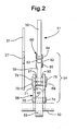
Figure 2 is a cross section on the line II - II ofFigure 1 , and -
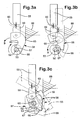
Figures 3a, 3b and 3c are diagrammatic representations of the assembly shown inFigures 1 and2 indicating sequential positions of components of the assembly when in operation and in the event the components striking an obstruction. - Referring now to
Figures 1 and2 of the drawings, there is shown ahammer assembly 51 for use in glass bottle breaking apparatus of the kind disclosed inWO 2004/067179 . Such apparatus includes ahopper 17 for receiving bottles in bulk, one such bottle being shown at 47 lying on its side with its base in view, a lower portion of thehopper 17 being in the form of a grating comprising a plurality of spaced parallel stringers, one of which is shown at 27, which provide aback stop 31. - The
hammer assembly 51 comprises ashaft 52 having secured thereto a plurality of collars, one of which is shown at 53, a plurality of link means, one of which is shown at 54, and a plurality of hammers, one of which is shown at 55. Each of thecollars 53 is provided with aneccentric aperture 56 in addition to itscentral aperture 57. - Each of the link means 54 comprises a gooseneck shaped
base link 58, anintermediate link 59 and abicycle chain link 60. - Each
base link 58 comprises twoidentical webs edge 63, a flattrailing edge 64 contiguous with arear entry cavity 65 having a concave wall, the radius of which corresponds with the radius of theshaft 52, and aflat base 66 contiguous with a trailingconcave recess 67, the radius of which also corresponds with the radius of theshaft 52. The twowebs bridge 68. As shown, thebridge 68 comprises abolt 69, secured by means of anut 70, and aspacer tube 71 through which the shank of thebolt 69 extends, thetube 71 being located between thewebs webs first aperture 72 between thecavity 65 and therecess 67 and asecond aperture 73 adjacent thetrailing edge 64. Eachbase link 58 is connected to a corresponding one of thecollars 53 by acorresponding bolt 74, the shank of which extends through thefirst aperture 72 of thewebs eccentric aperture 56 of thecollar 53 and thebolt 74 being secured by anut 75, whereby thebase link 56 is freely pivotable relative to thecorresponding collar 53. - The
intermediate link 59 is substantially rectangular in configuration havingrounded corners rounded corners intermediate link 59 is connected to acorresponding base link 58 by means of abolt 78 the shank of which extends through thesecond aperture 73 of thewebs intermediate link 59 and thebolt 78 being secured by anut 79; there beingwashers bolt 78 on opposite sides of theintermediate link 59 for centering theintermediate link 59 relative to thebolt 78 whereby theintermediate link 59 is freely pivotable relative to thebase link 58. - The
bicycle chain link 60 comprises a pair ofelongate plates studs plates respective studs plates bicycle chain link 60 is connected to a correspondingintermediate link 59 by means of a lower one 85 of thestuds intermediate link 59, whereby thebicycle chain link 60 is freely pivotable relative to theintermediate link 59. - Each of the
hammers 55 is of elongate rectangular configuration, one corner of which is rounded, as shown at 86, and provided with an aperture (not shown) adjacent therounded corner 86. Each of thehammers 55 is connected to a correspondingbicycle chain link 60 by means of the upper one 84 of thestuds long edge 87 of thehammer 55 having therounded corner 86 is a trailing edge and thehammer 55 is freely pivotable relative to thebicycle chain link 60. - In operation, the
shaft 52 is driven so that it rotates in a clockwise direction when viewed inFigure 1 . In consequence, the path of thehammers 55 extends arcuately into and through thehopper 17, as indicated by the arrow "A" inFigure 1 , and towards and through theback stop 31 such that thehammers 55 successively impact onbottles 47 located in the path against theback stop 31 causing breakage of thebottles 47. - Referring now to
Figures 3a, 3b and 3c in addition toFigure 1 , the configuration of thehammer assembly 51 is such that theconcave recess 67 contiguous with thebase 66 of each of thebase links 58 abuts theshaft 52 but, should a fragment of glass become lodged betweenadjacent stringers 27 and not be dislodged by immediate impact of an adjacent one of thehammers 55 and thereby become anobstruction 88, the link means 54 associated with thehammer 55 striking theobstruction 88 would wind up on theshaft 52 and thehammer 55 would move around theobstruction 88, thereby avoiding jamming. - In
Figure 3a , abase link 58 is shown abutting theobstruction 88. Since the leadingedge 63 of thebase link 58 is convex, it acts as a cam surface with regard toobstruction 88 in that the reaction with theobstruction 88 causes thebase link 58 to turn in a counter-clockwise direction relative to theshaft 52, when viewed inFigure 3a and indicated by the arrow "B", as theshaft 52 continues to turn in a clockwise direction. - The
base link 58 thus passes under theobstruction 88, as shown inFigure 3b , and the leading edge of theintermediate link 59 then abuts theobstruction 88. Since theintermediate link 59 is pivotally connected to thebase link 58, this also passes ' under the obstruction, as shown inFigure 3c . However, this is only possible because thebase link 58 is provided with therear entry cavity 65 which accommodates an adjacent portion of theshaft 52 as the link means 54 combination of thebase link 58 and theintermediate link 59 winds up on theshaft 52 and, finally, thehammer 55 passes under theobstruction 88, as shown in chain-dotted lines inFigure 3c , the radial displacement between the distal end of thehammer 55 and theshaft 52 having effectively been reduced. - It will be appreciated, therefore, that any impact of the
base link 58, theintermediate link 59 and thehammer 55 which did not result in immediate dislodging of theobstruction 88 would not result in arresting operation of thehammer assembly 51. However, as theshaft 52 continues to rotate, such impacts would, over time, result in theobstruction 88 becoming dislodged without the glass bottle breaking apparatus having to be shut down in order that theobstruction 88 may be removed manually. - It will also be appreciated that the above-described sequence is for illustrative purposes only. It cannot be predicted as to where any
obstruction 88 may become lodged, if at all, and it is possible that, if there should be anyobstruction 88, it may only be struck by ahammer 55 or a combination of anintermediate link 59 and ahammer 55. In any event, if there should be present anysuch obstruction 88 and thehammer assembly 51 is in operation and striking of theobstruction 88 does not dislodge theobstruction 88, thehammer assembly 51 will configure itself in the manner described with reference toFigures 1 and3a to 3c and jamming should be avoided. - A further advantage derives from the
hammer assembly 51 in that the presence of thebridge 68, in the described embodiment provided by thebolt 69, thenut 70 and thespacer tube 71, of eachbase link 58 prevents the correspondingintermediate link 59 from pivoting beyond 90 degrees forwardly in the direction of rotation of theshaft 52 beyond the position shown inFigure 1 , until theshaft 52 itself turns beyond that degree of arc. Since thecorresponding hammer 55 is spaced only a short distance from theintermediate link 59, its movement is also limited until it abuts theintermediate link 59. The result is that each of theintermediate links 59 and theircorresponding hammers 55 do not swing downwardly as soon as they pass the positions shown inFigure 1 . - This, of course, will be the situation when the
hammer assembly 51 is inoperative in that some of theintermediate links 59 and theircorresponding hammers 55, more particularly those that have swung past the position shown inFigure 1 when thehammer assembly 51 last became inoperative but which had not yet reached the position of depending downwardly from theshaft 52, would extend radially outwardly from theshaft 52. This provides greater moment than if theintermediate links 59 and theircorresponding hammers 55 were to hang downwardly and thereby assists a drive motor on start-up. Coincidently,intermediate links 59 and theircorresponding hammers 55 located on the other side of theshaft 52 on start-up would hang down and would provide lesser moment and this, also, would assist the drive motor on start-up. - It will be appreciated that each
base link 58, instead of being constructed by assembling together thewebs bridge 68 formed by thebolt 69, thenut 70 and thespacer tube 71, may be manufactured as a single unit by, for example, casting or milling.
Claims (3)
- A hammer assembly (51) for glass bottle breaking apparatus comprising a shaft (52), a series of carriers (53) secured on the shaft (52) and spaced one from another longitudinally of the shaft (52), a series of links (58) each being pivotally connected to a corresponding one of the carriers (53) and a series of hammers (55) each being connected for pivotal movement relative to a corresponding one of the links (58) characterised in that each of the links (58) is provided with a curved profile (65) for locating an adjacent portion of the shaft (52) so that if, when the assembly (51) located in the apparatus is in operation, any hammer (55) should strike an obstruction (88) without dislodging the obstruction (88) immediately, the corresponding link (58) pivots relative to the shaft (52) such that an adjacent portion of the shaft (52) is located within the curved profile (65) of the link (58) thereby reducing a radial displacement between the link (58) and the shaft (52) and causing the hammer (55) to be withdrawn from the obstruction (88).
- An assembly as claimed in Claim 1 characterised in that there is provided a plurality of sets of links (58, 59, 60) each set connecting a corresponding hammer (55) to a corresponding carrier (53), and the links (58, 59, 60) of each set being pivotally connected one to another in series and including one of the links (58) provided with the profile (65) for locating the adjacent portion of the shaft (52).
- An assembly as claimed in Claim 2 characterised in that each link (58) provided with the profile (65) for locating the adjacent portion of the shaft (52) is also provided with an abutment (69, 70, 71) for restricting pivotal movement of an adjacent link (59) relative thereto.
Applications Claiming Priority (2)
| Application Number | Priority Date | Filing Date | Title |
|---|---|---|---|
| GB0523792A GB0523792D0 (en) | 2005-11-22 | 2005-11-22 | Hammer assembly |
| PCT/GB2006/004273 WO2007060394A1 (en) | 2005-11-22 | 2006-11-16 | Hammer assembly |
Publications (2)
| Publication Number | Publication Date |
|---|---|
| EP1960107A1 EP1960107A1 (en) | 2008-08-27 |
| EP1960107B1 true EP1960107B1 (en) | 2013-04-10 |
Family
ID=35601016
Family Applications (1)
| Application Number | Title | Priority Date | Filing Date |
|---|---|---|---|
| EP20060808562 Not-in-force EP1960107B1 (en) | 2005-11-22 | 2006-11-16 | Hammer assembly |
Country Status (5)
| Country | Link |
|---|---|
| US (1) | US7735764B2 (en) |
| EP (1) | EP1960107B1 (en) |
| CN (1) | CN101304809B (en) |
| GB (1) | GB0523792D0 (en) |
| WO (1) | WO2007060394A1 (en) |
Families Citing this family (1)
| Publication number | Priority date | Publication date | Assignee | Title |
|---|---|---|---|---|
| CN104772190B (en) * | 2015-05-09 | 2017-10-10 | 蚌埠玻璃工业设计研究院 | A kind of plate glass cullet breaker |
Family Cites Families (6)
| Publication number | Priority date | Publication date | Assignee | Title |
|---|---|---|---|---|
| US3878995A (en) | 1973-09-04 | 1975-04-22 | Langhorn Construction Company | Refuse shredder and classifier |
| US5184781A (en) * | 1992-01-14 | 1993-02-09 | James Andela | Glass pulverizer |
| CN2137180Y (en) * | 1992-06-16 | 1993-06-30 | 王高亮 | Adjustable hammer |
| US5944268A (en) | 1996-05-10 | 1999-08-31 | Andela Tool & Machine, Inc. | Multi-flail glass pulverizer |
| GB0302150D0 (en) | 2003-01-30 | 2003-03-05 | Inqbator Ltd | Glass bottle breaking apparatus |
| CN2609660Y (en) * | 2003-04-23 | 2004-04-07 | 中国凯盛国际工程公司 | Glass disintegrator |
-
2005
- 2005-11-22 GB GB0523792A patent/GB0523792D0/en not_active Ceased
-
2006
- 2006-11-16 CN CN2006800422844A patent/CN101304809B/en not_active Expired - Fee Related
- 2006-11-16 WO PCT/GB2006/004273 patent/WO2007060394A1/en not_active Ceased
- 2006-11-16 EP EP20060808562 patent/EP1960107B1/en not_active Not-in-force
- 2006-11-16 US US12/088,021 patent/US7735764B2/en not_active Expired - Fee Related
Also Published As
| Publication number | Publication date |
|---|---|
| US7735764B2 (en) | 2010-06-15 |
| US20090218427A1 (en) | 2009-09-03 |
| WO2007060394A1 (en) | 2007-05-31 |
| GB0523792D0 (en) | 2006-01-04 |
| CN101304809B (en) | 2011-05-11 |
| EP1960107A1 (en) | 2008-08-27 |
| CN101304809A (en) | 2008-11-12 |
Similar Documents
| Publication | Publication Date | Title |
|---|---|---|
| US5562257A (en) | Double rotor hammermill | |
| CN1239028A (en) | Modified cage member for impact mechanism | |
| US8727254B2 (en) | Paddle assembly | |
| JPS60238162A (en) | Disk for hammer mill disk rotor | |
| US10099224B2 (en) | Material reducing device | |
| CN112295886A (en) | Disc sieves for separating solid materials | |
| US7735764B2 (en) | Hammer assembly | |
| CA2613956A1 (en) | Hammermill hammer | |
| US20140175201A1 (en) | Material Reducing Device | |
| CN110876260A (en) | Fragmentation device | |
| AU2020318699B2 (en) | Drill head for creating a borehole in the ground | |
| CN106944194B (en) | Pipe tobacco recovery system and its spirally useless cigarette breaker | |
| CN101166580B (en) | Crushing device | |
| JP3078248B2 (en) | Crusher with oscillating collision plate | |
| EP2976157B1 (en) | Material reducing device | |
| JP4411009B2 (en) | Crusher | |
| JP4548893B2 (en) | Glass smashing method and glass smashing apparatus | |
| CN203990765U (en) | Rotor structure for glass disintegrator | |
| JPH11292045A (en) | Bag breaking equipment | |
| CA3006348A1 (en) | Rock crusher for a potato harvester | |
| JP2007117851A (en) | Crusher | |
| CN212018544U (en) | Grate dredging equipment and coal sample screening device | |
| KR200356061Y1 (en) | Crusher for cutting steel-structure capable of preventing cutter-twisting | |
| JP3975022B2 (en) | Method and apparatus for removing lining material of tubular structure | |
| SU1418002A1 (en) | Arrangement for shredding metal waste |
Legal Events
| Date | Code | Title | Description |
|---|---|---|---|
| PUAI | Public reference made under article 153(3) epc to a published international application that has entered the european phase |
Free format text: ORIGINAL CODE: 0009012 |
|
| 17P | Request for examination filed |
Effective date: 20080508 |
|
| AK | Designated contracting states |
Kind code of ref document: A1 Designated state(s): AT BE BG CH CY CZ DE DK EE ES FI FR GB GR HU IE IS IT LI LT LU LV MC NL PL PT RO SE SI SK TR |
|
| DAX | Request for extension of the european patent (deleted) | ||
| 17Q | First examination report despatched |
Effective date: 20121127 |
|
| GRAP | Despatch of communication of intention to grant a patent |
Free format text: ORIGINAL CODE: EPIDOSNIGR1 |
|
| GRAS | Grant fee paid |
Free format text: ORIGINAL CODE: EPIDOSNIGR3 |
|
| GRAA | (expected) grant |
Free format text: ORIGINAL CODE: 0009210 |
|
| RIN1 | Information on inventor provided before grant (corrected) |
Inventor name: WALDRON, CHRISTOPHER, JOHN |
|
| AK | Designated contracting states |
Kind code of ref document: B1 Designated state(s): AT BE BG CH CY CZ DE DK EE ES FI FR GB GR HU IE IS IT LI LT LU LV MC NL PL PT RO SE SI SK TR |
|
| REG | Reference to a national code |
Ref country code: GB Ref legal event code: FG4D |
|
| REG | Reference to a national code |
Ref country code: CH Ref legal event code: EP Ref country code: AT Ref legal event code: REF Ref document number: 605685 Country of ref document: AT Kind code of ref document: T Effective date: 20130415 |
|
| REG | Reference to a national code |
Ref country code: IE Ref legal event code: FG4D |
|
| REG | Reference to a national code |
Ref country code: DE Ref legal event code: R096 Ref document number: 602006035630 Country of ref document: DE Effective date: 20130606 |
|
| REG | Reference to a national code |
Ref country code: GB Ref legal event code: 732E Free format text: REGISTERED BETWEEN 20130620 AND 20130626 |
|
| PG25 | Lapsed in a contracting state [announced via postgrant information from national office to epo] |
Ref country code: SI Free format text: LAPSE BECAUSE OF FAILURE TO SUBMIT A TRANSLATION OF THE DESCRIPTION OR TO PAY THE FEE WITHIN THE PRESCRIBED TIME-LIMIT Effective date: 20130410 |
|
| REG | Reference to a national code |
Ref country code: AT Ref legal event code: MK05 Ref document number: 605685 Country of ref document: AT Kind code of ref document: T Effective date: 20130410 |
|
| REG | Reference to a national code |
Ref country code: NL Ref legal event code: VDEP Effective date: 20130410 Ref country code: LT Ref legal event code: MG4D |
|
| PG25 | Lapsed in a contracting state [announced via postgrant information from national office to epo] |
Ref country code: NL Free format text: LAPSE BECAUSE OF FAILURE TO SUBMIT A TRANSLATION OF THE DESCRIPTION OR TO PAY THE FEE WITHIN THE PRESCRIBED TIME-LIMIT Effective date: 20130410 Ref country code: BE Free format text: LAPSE BECAUSE OF FAILURE TO SUBMIT A TRANSLATION OF THE DESCRIPTION OR TO PAY THE FEE WITHIN THE PRESCRIBED TIME-LIMIT Effective date: 20130410 Ref country code: LT Free format text: LAPSE BECAUSE OF FAILURE TO SUBMIT A TRANSLATION OF THE DESCRIPTION OR TO PAY THE FEE WITHIN THE PRESCRIBED TIME-LIMIT Effective date: 20130410 Ref country code: SE Free format text: LAPSE BECAUSE OF FAILURE TO SUBMIT A TRANSLATION OF THE DESCRIPTION OR TO PAY THE FEE WITHIN THE PRESCRIBED TIME-LIMIT Effective date: 20130410 Ref country code: AT Free format text: LAPSE BECAUSE OF FAILURE TO SUBMIT A TRANSLATION OF THE DESCRIPTION OR TO PAY THE FEE WITHIN THE PRESCRIBED TIME-LIMIT Effective date: 20130410 Ref country code: GR Free format text: LAPSE BECAUSE OF FAILURE TO SUBMIT A TRANSLATION OF THE DESCRIPTION OR TO PAY THE FEE WITHIN THE PRESCRIBED TIME-LIMIT Effective date: 20130711 Ref country code: FI Free format text: LAPSE BECAUSE OF FAILURE TO SUBMIT A TRANSLATION OF THE DESCRIPTION OR TO PAY THE FEE WITHIN THE PRESCRIBED TIME-LIMIT Effective date: 20130410 Ref country code: PT Free format text: LAPSE BECAUSE OF FAILURE TO SUBMIT A TRANSLATION OF THE DESCRIPTION OR TO PAY THE FEE WITHIN THE PRESCRIBED TIME-LIMIT Effective date: 20130812 Ref country code: IS Free format text: LAPSE BECAUSE OF FAILURE TO SUBMIT A TRANSLATION OF THE DESCRIPTION OR TO PAY THE FEE WITHIN THE PRESCRIBED TIME-LIMIT Effective date: 20130810 Ref country code: ES Free format text: LAPSE BECAUSE OF FAILURE TO SUBMIT A TRANSLATION OF THE DESCRIPTION OR TO PAY THE FEE WITHIN THE PRESCRIBED TIME-LIMIT Effective date: 20130721 |
|
| PG25 | Lapsed in a contracting state [announced via postgrant information from national office to epo] |
Ref country code: PL Free format text: LAPSE BECAUSE OF FAILURE TO SUBMIT A TRANSLATION OF THE DESCRIPTION OR TO PAY THE FEE WITHIN THE PRESCRIBED TIME-LIMIT Effective date: 20130410 Ref country code: LV Free format text: LAPSE BECAUSE OF FAILURE TO SUBMIT A TRANSLATION OF THE DESCRIPTION OR TO PAY THE FEE WITHIN THE PRESCRIBED TIME-LIMIT Effective date: 20130410 Ref country code: CY Free format text: LAPSE BECAUSE OF FAILURE TO SUBMIT A TRANSLATION OF THE DESCRIPTION OR TO PAY THE FEE WITHIN THE PRESCRIBED TIME-LIMIT Effective date: 20130410 Ref country code: BG Free format text: LAPSE BECAUSE OF FAILURE TO SUBMIT A TRANSLATION OF THE DESCRIPTION OR TO PAY THE FEE WITHIN THE PRESCRIBED TIME-LIMIT Effective date: 20130710 |
|
| PG25 | Lapsed in a contracting state [announced via postgrant information from national office to epo] |
Ref country code: DK Free format text: LAPSE BECAUSE OF FAILURE TO SUBMIT A TRANSLATION OF THE DESCRIPTION OR TO PAY THE FEE WITHIN THE PRESCRIBED TIME-LIMIT Effective date: 20130410 Ref country code: CZ Free format text: LAPSE BECAUSE OF FAILURE TO SUBMIT A TRANSLATION OF THE DESCRIPTION OR TO PAY THE FEE WITHIN THE PRESCRIBED TIME-LIMIT Effective date: 20130410 Ref country code: SK Free format text: LAPSE BECAUSE OF FAILURE TO SUBMIT A TRANSLATION OF THE DESCRIPTION OR TO PAY THE FEE WITHIN THE PRESCRIBED TIME-LIMIT Effective date: 20130410 Ref country code: EE Free format text: LAPSE BECAUSE OF FAILURE TO SUBMIT A TRANSLATION OF THE DESCRIPTION OR TO PAY THE FEE WITHIN THE PRESCRIBED TIME-LIMIT Effective date: 20130410 |
|
| REG | Reference to a national code |
Ref country code: GB Ref legal event code: 732E Free format text: REGISTERED BETWEEN 20140109 AND 20140115 |
|
| PLBE | No opposition filed within time limit |
Free format text: ORIGINAL CODE: 0009261 |
|
| STAA | Information on the status of an ep patent application or granted ep patent |
Free format text: STATUS: NO OPPOSITION FILED WITHIN TIME LIMIT |
|
| PG25 | Lapsed in a contracting state [announced via postgrant information from national office to epo] |
Ref country code: RO Free format text: LAPSE BECAUSE OF FAILURE TO SUBMIT A TRANSLATION OF THE DESCRIPTION OR TO PAY THE FEE WITHIN THE PRESCRIBED TIME-LIMIT Effective date: 20130410 Ref country code: IT Free format text: LAPSE BECAUSE OF FAILURE TO SUBMIT A TRANSLATION OF THE DESCRIPTION OR TO PAY THE FEE WITHIN THE PRESCRIBED TIME-LIMIT Effective date: 20130410 |
|
| 26N | No opposition filed |
Effective date: 20140113 |
|
| REG | Reference to a national code |
Ref country code: DE Ref legal event code: R097 Ref document number: 602006035630 Country of ref document: DE Effective date: 20140113 |
|
| REG | Reference to a national code |
Ref country code: CH Ref legal event code: PL |
|
| PG25 | Lapsed in a contracting state [announced via postgrant information from national office to epo] |
Ref country code: LI Free format text: LAPSE BECAUSE OF NON-PAYMENT OF DUE FEES Effective date: 20131130 Ref country code: CH Free format text: LAPSE BECAUSE OF NON-PAYMENT OF DUE FEES Effective date: 20131130 Ref country code: MC Free format text: LAPSE BECAUSE OF FAILURE TO SUBMIT A TRANSLATION OF THE DESCRIPTION OR TO PAY THE FEE WITHIN THE PRESCRIBED TIME-LIMIT Effective date: 20130410 |
|
| REG | Reference to a national code |
Ref country code: FR Ref legal event code: ST Effective date: 20140731 |
|
| REG | Reference to a national code |
Ref country code: IE Ref legal event code: MM4A |
|
| PG25 | Lapsed in a contracting state [announced via postgrant information from national office to epo] |
Ref country code: DE Free format text: LAPSE BECAUSE OF NON-PAYMENT OF DUE FEES Effective date: 20140603 |
|
| REG | Reference to a national code |
Ref country code: DE Ref legal event code: R119 Ref document number: 602006035630 Country of ref document: DE Effective date: 20140603 |
|
| PG25 | Lapsed in a contracting state [announced via postgrant information from national office to epo] |
Ref country code: IE Free format text: LAPSE BECAUSE OF NON-PAYMENT OF DUE FEES Effective date: 20131116 |
|
| PG25 | Lapsed in a contracting state [announced via postgrant information from national office to epo] |
Ref country code: FR Free format text: LAPSE BECAUSE OF NON-PAYMENT OF DUE FEES Effective date: 20131202 |
|
| PG25 | Lapsed in a contracting state [announced via postgrant information from national office to epo] |
Ref country code: TR Free format text: LAPSE BECAUSE OF FAILURE TO SUBMIT A TRANSLATION OF THE DESCRIPTION OR TO PAY THE FEE WITHIN THE PRESCRIBED TIME-LIMIT Effective date: 20130410 |
|
| PG25 | Lapsed in a contracting state [announced via postgrant information from national office to epo] |
Ref country code: LU Free format text: LAPSE BECAUSE OF NON-PAYMENT OF DUE FEES Effective date: 20131116 Ref country code: HU Free format text: LAPSE BECAUSE OF FAILURE TO SUBMIT A TRANSLATION OF THE DESCRIPTION OR TO PAY THE FEE WITHIN THE PRESCRIBED TIME-LIMIT; INVALID AB INITIO Effective date: 20061116 |
|
| PGFP | Annual fee paid to national office [announced via postgrant information from national office to epo] |
Ref country code: GB Payment date: 20151230 Year of fee payment: 10 |
|
| GBPC | Gb: european patent ceased through non-payment of renewal fee |
Effective date: 20161116 |
|
| PG25 | Lapsed in a contracting state [announced via postgrant information from national office to epo] |
Ref country code: GB Free format text: LAPSE BECAUSE OF NON-PAYMENT OF DUE FEES Effective date: 20161116 |