EP1959692B1 - A method for compensating hardware misalignments in a camera - Google Patents
A method for compensating hardware misalignments in a camera Download PDFInfo
- Publication number
- EP1959692B1 EP1959692B1 EP07102655A EP07102655A EP1959692B1 EP 1959692 B1 EP1959692 B1 EP 1959692B1 EP 07102655 A EP07102655 A EP 07102655A EP 07102655 A EP07102655 A EP 07102655A EP 1959692 B1 EP1959692 B1 EP 1959692B1
- Authority
- EP
- European Patent Office
- Prior art keywords
- camera
- coordinates
- pan
- calibration data
- tilt
- Prior art date
- Legal status (The legal status is an assumption and is not a legal conclusion. Google has not performed a legal analysis and makes no representation as to the accuracy of the status listed.)
- Active
Links
- 238000000034 method Methods 0.000 title claims abstract description 38
- 230000003287 optical effect Effects 0.000 claims description 28
- 230000000295 complement effect Effects 0.000 claims description 18
- 238000004590 computer program Methods 0.000 claims description 2
- 238000012545 processing Methods 0.000 claims description 2
- 230000006870 function Effects 0.000 description 8
- 238000006073 displacement reaction Methods 0.000 description 6
- 238000004519 manufacturing process Methods 0.000 description 4
- 230000001419 dependent effect Effects 0.000 description 2
- 230000000694 effects Effects 0.000 description 2
- 238000005259 measurement Methods 0.000 description 2
- 238000013461 design Methods 0.000 description 1
- 238000012886 linear function Methods 0.000 description 1
- 238000013507 mapping Methods 0.000 description 1
- 230000003068 static effect Effects 0.000 description 1
- 238000012546 transfer Methods 0.000 description 1
Images


Classifications
-
- H—ELECTRICITY
- H04—ELECTRIC COMMUNICATION TECHNIQUE
- H04N—PICTORIAL COMMUNICATION, e.g. TELEVISION
- H04N17/00—Diagnosis, testing or measuring for television systems or their details
- H04N17/002—Diagnosis, testing or measuring for television systems or their details for television cameras
-
- H—ELECTRICITY
- H04—ELECTRIC COMMUNICATION TECHNIQUE
- H04N—PICTORIAL COMMUNICATION, e.g. TELEVISION
- H04N7/00—Television systems
- H04N7/18—Closed-circuit television [CCTV] systems, i.e. systems in which the video signal is not broadcast
- H04N7/183—Closed-circuit television [CCTV] systems, i.e. systems in which the video signal is not broadcast for receiving images from a single remote source
- H04N7/185—Closed-circuit television [CCTV] systems, i.e. systems in which the video signal is not broadcast for receiving images from a single remote source from a mobile camera, e.g. for remote control
Definitions
- the present invention generally relates to a method for compensating hardware misalignments in a camera, a camera and a system comprising a camera and a user interface apparatus.
- PTZ Pan Tilt Zoom
- dome cameras are very popular.
- the main reason for this is that the operator is able to remotely manoeuvre these cameras. For instance, if the operator discovers a suspect object he may direct the camera towards this object by using a steering motor system comprised in the camera. Further, in some cameras, it is also possible to zoom in or out in order to get a desired field of view.
- a high quality steering motor system is of great importance. Firstly, the number of steps is important, since a large number of steps makes a precise control of the camera possible. Secondly, it is important that the camera is designed and mounted correctly, since an incorrect mounting will deteriorate the control of the camera.
- the US patent application 2002/003965 relates to camera lens systems having optical characteristics (such as zoom and focus) that can be modified while the camera is in use; the lens system is for mounting on a camera that has its own sensors for delivering signals representative of the angular position of the camera relative to its stand.
- 2002/003965 pertains to a method for calibrating a camera lens, which calibration process involves two stages. A first stage involves determining intrinsic characteristics of the lens system and generating a computer file containing these characteristics. The first stage is performed once for ail.
- the second stage is performed each time the camera is in use and involves defiling transfer functions between signals from the sensors sensing the orientation of the camera and sensors sensing the setting of the lens system and the real characteristics, based on the file and on signals obtained by shooting characteristic points in the scene to be displayed.
- the paper entitled "A High-precision Camera Operation Parameter Measurement System and its Application to Image Motion Inferring” by Zheng et al. relates to a method for calibrating internal parameters of a camera.
- the paper by Zheng et al. pertains to a high-precision camera operation parameter measurement system, which system is designed to provide camera operation parameters with a high precision for image coding applications.
- Pan/tilt sensors are mounted on a platform on which the camera head is fixed. In order to improve the accuracy of the effective focal length two images taken from different distances without changing the lens setting are used.
- the US patent application 2003/210329 A1 relates to a multiple camera video system and methods for operating such a system.
- the system may include a plurality of cameras located around a stadium.
- the pan head of a master camera is utilized to adjust the telemetry and zoom of the master camera.
- the telemetry and zoom parameters of the master camera are then used to calculate corresponding telemetry, zoom and/or other parameters for each of the plurality of cameras.
- the calibration program preferably creates a texture map of the playing surface (of the stadium) which is associated with actual pan and tilt positioning coordinates for each camera.
- the initial playing filed mapping is carried out by selecting a plurality of points around the filed and determining the actual coordinates in space.
- a positioning device may be used to generate the absolute positioning coordinates for a plurality of positions by moving the positioning device from one point to the next. Selecting easily identifiable points such as the various corners and intersections of lines on a tennis court make the calibration for each camera easier. Each of the plurality of cameras must be aimed at the location of each of the points, and the pan and tilt settings must be captured.
- an objective of the invention is to solve or at least reduce the problems discussed above.
- an objective is to provide a method for compensating hardware misalignments in a camera.
- the above object is provided according to a first aspect by a method for compensating hardware misalignments in a camera as set out in claim 1.
- An advantage of this method is that absolute coordinates are achieved, which e.g. means that it is possible to return to a specific point if knowing the coordinates.
- Another advantage of achieving absolute coordinates is that an improved mask function may be achieved. For instance, if a certain area of the image, such as a door, is marked by a privacy mask, the coordinates of this privacy mask will be remembered independent of the mechanical coordinates of the camera. Yet another advantage is that it is possible to preset positions.
- Still an advantage is that the function of the camera is less dependent of manufacturing inaccuracies.
- the manoeuvrable part may comprise a zooming optical system
- the method may then comprise receiving at least one zoom position of said zooming optical system, reading predetermined calibration data corresponding to said at least one zoom position from said memory, and determining compensated coordinates based upon said received at least one zoom position and said pre-determined calibration data.
- optical misalignments which may vary for different zoom positions, may be compensated.
- the method may further comprise transmitting said compensated coordinates from said camera to a user interface apparatus, and presenting said compensated coordinates on said user interface apparatus.
- An advantage of this is that the user of the camera may see the position of the camera in absolute coordinates.
- the method may further comprise transmitting image data to an image handling device, transmitting said compensated coordinates to said image data handling device, and processing said image data and said compensated coordinates in said image data handling device.
- the method may further comprise receiving camera target coordinates, reading pre-determined calibration data corresponding to said received camera target coordinates from said memory comprised in said camera, determining camera target mechanical coordinates based upon said received camera target coordinates and said pre-determined calibration data, and moving said manoeuvrable part of said camera in accordance to said determined camera target mechanical coordinates.
- the camera target coordinates may be received from a user interface apparatus or from an image handling device.
- An advantage of this is that if a position is given by the user, via a user interface apparatus, in compensated coordinates, these compensated coordinates are transformed into mechanical coordinates, and the camera may be moved to the given position, which for instance may be achieved by a mouse click ir an image.
- the optical system of said manoeuvrable part may comprise a zooming optical system
- said processor may further be configured to receive at least one zoom position from said zooming optical system, and to determine compensated coordinates based upon said at least one received zoom position and said pre-determined calibration data.
- the camera may further comprise a transmitter adapted to transmit said compensated coordinates from said camera to a user interface apparatus.
- the transmitter may further be adapted to transmit image data and said compensated coordinates to an image handling device.
- the processor may further be configured to receive camera target coordinates, to read pre-determined calibration data corresponding to said received camera target coordinates from said memory comprised in said camera, and to determine camera target mechanical coordinates based upon said received camera target coordinates and said pre-determined calibration data, and wherein said steering motor system may be configured to move said manoeuvrable part of said camera in accordance to said determined camera target mechanical coordinates.
- a system comprising a data network, a user interface apparatus connected to said data network, and at least one camera as described above.
- the above object is provided according to a fourth aspect by a computer program comprising software instructions arranged to perform the method as described above when downloaded and run in an apparatus.
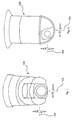
- Fig 1 illustrates an example of a PTZ (Pan Tilt Zoom) camera 100.
- This exemplified camera 100 is a network camera connected to a data network (not shown), such as a TCP/IP network. Control data is transmitted to the camera via said data network, and the image data captured by the camera 100 is transmitted via the data network to a user interface apparatus (not shown).
- a data network such as a TCP/IP network.
- Control data is transmitted to the camera via said data network, and the image data captured by the camera 100 is transmitted via the data network to a user interface apparatus (not shown).
- a manoeuvrable part of the camera 100 is arranged to rotate around a pan axis 102 and a tilt axis 104, wherein the pan axis 102 is perpendicular to the tilt axis 104, Most often, the pan range of a PTZ camera 100 is limited to about 360° by a mechanical stop, and the tilt range is in many cases about 180°.
- Fig 2 illustrates an example of a dome camera.
- the function of the dome camera 200 is similar to the PTZ camera 100.
- a manoeuvrable part of the camera 200 is rotatably arranged around a pan axis 202 and a tilt axis 204, wherein the pan axis 202 is perpendicular to the tilt axis 204.
- dome cameras are arranged to rotate freely around the pan axis.
- the tilt range of a dome camera is in many cases about 180°.
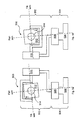
- a generalised embodiment of both the PTZ camera 100 and the dome camera 200 may be a camera 300 illustrated in fig 3 .
- the camera 300 comprises a manoeuvrable part 302 and a fixed part 304.
- the fixed part may also be referred to as a mounting part, i.e, when mounting the camera this part is attached to e.g. the ceiling.
- the fixed part 304 comprises a mounting bracket 306 adapted to be attached to e.g. a ceiling.
- This mounting bracket may also be used a stand, as is illustrated in fig 3a , although in most cases the camera is mounted in a ceiling or similar.
- the fixed part can comprise a pan steering motor 308.
- This pan steering motor 308 By using this pan steering motor 308 the manoeuvrable part 302 of the camera 300 is rotated around a pan axis.
- This motor 308 can be adapted to rotate freely, i.e, there are no mechanical stops, or the rotational range of the motor 308 may be limited by a mechanical stop. Such a mechanical stop may be achieved by a tap, or by a wire.
- the pan steering motor 308 is connected to a tilt steering motor 310. which, hence, is part of the manoeuvrable part 302 of the camera 300. As the pan steering motor 308, this tilt steering motor 310 may be adapted to rotate freely, or the tilt steering motor may be limited by a mechanical stop.
- the tilt steering motor 310 is in turn connected to a camera block 312, which in turn comprises an optical system 314. Hence, by using the tilt steering motor 310 the camera block 312 is rotated around a tilt.axis.
- the pan steering motor 308 has rotated the manoeuvrable part 302 half a turn, i.e. 180 degrees
- the tilt steering motor 310 has rotated the camera block 312 half a turn, i.e. 180 degrees, which has the effect, in this embodiment, that the same field of view is reached.
- the mechanical coordinates of the pan steering motor and the tilt steering motor, respectively, in fig 3a is referred to as an upright coordinates
- the mechanical coordinates of the pan steering motor and the tilt steering motor, respectively, in fig 3b is referred to as flipped coordinates. These flipped coordinates are considered as complementary coordinates to the upright coordinates.
- the space of the upright coordinates is herein referred to as upright space and the space of the flipped coordinates are referred to as flipped space, in an embodiment of a camera having a pan range of 360 degrees and a tilt range of 180 degrees, the upright coordinates may be defined as: Pan coordinate: -180° ⁇ P U ⁇ 180° Tilt coordinate: -90° ⁇ T U ⁇ 0°
- the two complementary positions should theoretically display the exact same view for the user, with the difference that the camera is upside-down in the flipped position. This can automatically be fixed by rotating the image digitally when the camera is in the flipped coordinate space.
- Fig 4a illustrate a camera 400, similar to the camera 300 illustrated in fig 3a , but unlike this camera 300, the camera block 412 of the camera 400 is displaced. This implies that the pan axis as well as the tilt axis are displaced, which, of course, is a disadvantage.
- Fig 4b illustrates the camera 400 in a complementary position. Numerals with the last two digits of fig 3a and fig 3b correspond to the numerals with the two last digits of fig 4a and fig 4b . Such a displacement may arise when the camera block is mounted or because of other manufacturing inaccuracies.
- the displacement error is expressed using complementary coordinates. If the image is digitally rotated, a point of the image received in the position illustrated in fig 4a will hence be shown differently, in terms of placement, in the image received in the position illustrated in fig 4b . In the exemplified situation of fig 4a and 4b , the image will be displaced horizontally, as well as vertically.
- Fig 5a illustrates a camera 500, similar to the camera 300 illustrated in fig 3a , but unlike this camera 300, the camera block 512 of the camera 500 is rotationally displaced.
- Fig 5b illustrates the camera 500 in a complementary position. Numerals with the last two digits of fig 3a and fig 3b correspond to the numerals with the two last digits of fig 5a and fig 5b . Such a rotational displacement may arise when the camera block is mounted or because of other manufacturing inaccuracies.
- the displacement of the camera block 516 implies that a point of the image is shown differently, in terms of placement, in the image received in the position of the camera 500 illustrated in fig 5a and in the complementary position of the camera 500 illustrated in fig 5b .
- the problem that a point in the image is shown differently in an upright position and in a flipped position may, for instance, also arise because of hardware misalignments in the steering motor system, which is herein exemplified as the pan steering motor 308/408/508 and the tilt steering motor 310/410/510, mounting inaccuracies between the mounting bracket 306/408/506 and the pan steering motor 308/408/508, mounting inaccuracies between the pan steering motor 308/408/508 and the tilt steering motor 310/410/518, mounting inaccuracies between the tilt steering motor 310/410/510 and the camera block 312/412/512 and other hardware misalignment, such as optical misalignments.
- hardware misalignments in the steering motor system which is herein exemplified as the pan steering motor 308/408/508 and the tilt steering motor 310/410/510, mounting inaccuracies between the mounting bracket 306/408/506 and the pan steering motor 308/408/508, mounting inaccuracies between the
- a pan-tilt camera may be achieved in a number of ways, for instance the tilt steering motor and the pan steering motor may switch places, i.e. the tilt steering motor may be attached to the mounting bracket instead of the pan steering motor as illustrated in fig 3a, 3b , 4a, 4b , 5a and 5b .
- the tilt steering motor may be attached to the mounting bracket instead of the pan steering motor as illustrated in fig 3a, 3b , 4a, 4b , 5a and 5b .
- hardware misalignments can result in an unwanted displacement of the image.
- one way of reaching a position is by using complementary coordinates.
- a position may also be reached by using different mechanical coordinates if, for instance, the pan range of the camera is equal or greater than 360°.
- Fig 6 illustrates a side view of a camera 600, similar to the camera 300 illustrated in fig 3a and 3b .
- Numerals with the last two digits of fig 3a and fig 3b correspond to the numerals with the two last digits of fig 6 .
- the optical system 614 comprises a number of lenses 616. If the camera 600 comprises a zooming function, the lenses 616 of the optical system 614 are adapted to be moved in relation to each other.
- Fig 7 illustrates a side view of an exemplified camera 700. Similar to the camera 300 illustrated in fig 3a and 3b . Numerals with the last two digits of the example illustrated in fig 3a and fig 3b correspond to the numerals with the two last digits of the example illustrated in fig 7 .
- the lenses 716 comprised in the optical system 714 are misaligned. Such misalignment may be a result of the mounting of the lenses 716, a result of inaccuracies in the lenses 716 or a combination of them.
- the error of the misaligned lenses 716 can depend of the zoom position, in other words the degree of zoom, of the optical system 714 and/or the focus position of the optical system 714.
- the misalignment of the lenses 716 may arise because the lenses are not directed properly or that the lenses 716 are not placed correctly in relation to each other. If the zoom position of the optical system and/or the focus position are changed the error may in turn change.
- a calibration procedure is performed for the camera.
- the calibration procedure is performed for each camera individually.
- the calibration procedure is preferably made during the manufacturing of the camera, i.e. before the camera reaches the end customer.
- FIG. 8 A possible set-up, when performing the calibration procedure, is illustrated in fig 8 .
- the camera 800 is directed towards a reference mark 802.
- the calibration procedure for a camera without zooming functionality may be described as:
- the calibration data is determined and stored in the memory.
- the calibration data may be determined by calculating a difference between the mechanical coordinates and comparing this difference with a theoretic difference.
- the pan position of the first and second position can be determined as +178.7° and -181.3°, respectively.
- the difference between theses two values 180°, i.e. the manoeuvrable part of the camera is rotated half a turn in order to reach the second position from the first position.
- the calibration data may upon the calibration procedure comprise -1.3° in pan compensation for the present zoom position.
- the memory can be placed in the camera.
- an intermediate position may be calculate.
- Fig 9 illustrates an example of an image 900 comprising a theoretic reference center point 902, i.e. the center point for a camera without hardware misalignments, a first position center point 904, i.e. the center point achieved in the first position for a camera having hardware misalignments, and a second center point 906, i.e. the center point achieved in the second position for the camera having hardware misalignments, wherein the second position is a complementary position to the first position.
- a theoretic reference center point 902 i.e. the center point for a camera without hardware misalignments
- a first position center point 904 i.e. the center point achieved in the first position for a camera having hardware misalignments
- a second center point 906 i.e. the center point achieved in the second position for the camera having hardware misalignments
- first position 904 and the second position 906 are complementary positions, a position between these two positions, i.e. an intermediate position, illustrated as point 908, may be used as an approximation of a reference center point.
- a horizontal compensation component - ⁇ x and a vertical compensation component - ⁇ y are to be used, as illustrated in fig 9 .
- the compensation components ⁇ x and ⁇ y can be approximated to be the same for each position of the upright space, and, similarly, the compensation components - ⁇ x and - ⁇ y can be approximated to be the same for each position of the flipped space.
- the misalignment error of the mechanical misalignments such as the ones illustrated in fig 4a, 4b , 5a and 5b , may be referred to as a statical error.
- the misalignments caused by the optical misalignment may give rise to a dynamic error, wherein the dynamic error depends on the zoom position of the camera, as schematically illustrated in fig 10 .
- the dynamic error is in most cases not a linear function of the zoom positions, although illustrated in such a way in fig 10 .
- the calibration procedure described above and illustrated in fig 10 . may be repeated for a number of zoom positions, or in other words zoom degrees.
- a table may be achieved by measure the compensation components for the zoom degrees of 1X, 2X, 5X, 10X and 35X, respectively.
- the procedure starts at the highest zoom degree, such as 35X, since it is easier to find the exact position of the reference mark at higher zoom degrees.
- Fig 11a and 11b generally illustrates a method for compensating hardware misalignments in a camera.
- a first step 1100 mechanical coordinates are received and in a second step 1102 pre-determined calibration data corresponding to the mechanical coordinates is read from a memory.
- This memory may be comprised in the camera, and the calibration data may be achieved as described above.
- compensated coordinates are determined based upon the mechanical coordinates and the calibration data.
- a zoom position may be received, and, in a step 1108, pre-determined calibration data corresponding to the zoom position may be read from a memory.
- compensated coordinates may be determined based upon the zoom position and the pre-determined calibration data.
- the compensated coordinates may be transmitted to a user interface apparatus, and, in a step 1114, the compensated coordinates may be shown on the user interface apparatus.
- the compensated coordinates may be transmitted to an image handling device, and image data may be transmitted to the image handling device, step 1118.
- the compensated coordinates and the image data may be processed, step 1120.
- camera target coordinates may be received from a user interface apparatus, and, in a step 1124, pre-determined calibration data corresponding to the camera target coordinates may be read. Based upon the camera target coordinates and the pre-determined calibration data, camera target mechanical coordinates may be achieved, step 1126.
- Fig 12 generally illustrates an embodiment of a camera 1200 with built-in functionality for compensating hardware misalignments.
- the camera 1200 comprises a manoeuvrable part 1202, which in turn comprises an optical system 1204, and a fixed part 1206.
- a steering motor system 1208 is provided in order to control the manoeuvrable part 1202, a steering motor system 1208 is provided.
- a memory 1210 comprising pre-determined calibration data
- a processor 1212 and, optionally, a transmitter 1214 are provided.
- the memory 1210, the processor 1212 and the transmitter 1214 are comprised in the manoeuvrable part 1202, but they may also be comprised in the fixed part 1206 or in an external module.
- the transmitter 1214 may be a network interface card.
- the transmitter 1214 and the processor 1212 may be comprised in one and the same integrated circuit.
- Fig 13 generally illustrates a system 1300 comprising a data network 1302, a camera 1304 and a user interface apparatus 1306.
Abstract
Description
- The present invention generally relates to a method for compensating hardware misalignments in a camera, a camera and a system comprising a camera and a user interface apparatus.
- Today, PTZ (Pan Tilt Zoom) cameras and dome cameras are very popular. The main reason for this is that the operator is able to remotely manoeuvre these cameras. For instance, if the operator discovers a suspect object he may direct the camera towards this object by using a steering motor system comprised in the camera. Further, in some cameras, it is also possible to zoom in or out in order to get a desired field of view.
- In order to achieve a camera with a good control function, a high quality steering motor system is of great importance. Firstly, the number of steps is important, since a large number of steps makes a precise control of the camera possible. Secondly, it is important that the camera is designed and mounted correctly, since an incorrect mounting will deteriorate the control of the camera.
- If a zooming function is available in the camera, it is further important that the lenses in the lens system of the camera are mounted and directed properly. Otherwise, a displacement error will arise when using the zooming function.
- Hence, there is a need to deal with imperfections in camera direction operation.
- The
US patent application 2002/003965 relates to camera lens systems having optical characteristics (such as zoom and focus) that can be modified while the camera is in use; the lens system is for mounting on a camera that has its own sensors for delivering signals representative of the angular position of the camera relative to its stand. In more detail 2002/003965 pertains to a method for calibrating a camera lens, which calibration process involves two stages. A first stage involves determining intrinsic characteristics of the lens system and generating a computer file containing these characteristics. The first stage is performed once for ail. The second stage is performed each time the camera is in use and involves defiling transfer functions between signals from the sensors sensing the orientation of the camera and sensors sensing the setting of the lens system and the real characteristics, based on the file and on signals obtained by shooting characteristic points in the scene to be displayed. - The paper entitled "A High-precision Camera Operation Parameter Measurement System and its Application to Image Motion Inferring" by Zheng et al. relates to a method for calibrating internal parameters of a camera. In more detail the paper by Zheng et al. pertains to a high-precision camera operation parameter measurement system, which system is designed to provide camera operation parameters with a high precision for image coding applications. Pan/tilt sensors are mounted on a platform on which the camera head is fixed. In order to improve the accuracy of the effective focal length two images taken from different distances without changing the lens setting are used.
- The
US patent application 2003/210329 A1 relates to a multiple camera video system and methods for operating such a system. The system may include a plurality of cameras located around a stadium. The pan head of a master camera is utilized to adjust the telemetry and zoom of the master camera. The telemetry and zoom parameters of the master camera are then used to calculate corresponding telemetry, zoom and/or other parameters for each of the plurality of cameras. The calibration program preferably creates a texture map of the playing surface (of the stadium) which is associated with actual pan and tilt positioning coordinates for each camera. The initial playing filed mapping is carried out by selecting a plurality of points around the filed and determining the actual coordinates in space. A positioning device may be used to generate the absolute positioning coordinates for a plurality of positions by moving the positioning device from one point to the next. Selecting easily identifiable points such as the various corners and intersections of lines on a tennis court make the calibration for each camera easier. Each of the plurality of cameras must be aimed at the location of each of the points, and the pan and tilt settings must be captured. - In view of the above, an objective of the invention is to solve or at least reduce the problems discussed above. In particular, an objective is to provide a method for compensating hardware misalignments in a camera.
- The above object is provided according to a first aspect by a method for compensating hardware misalignments in a camera as set out in
claim 1. - An advantage of this method is that absolute coordinates are achieved, which e.g. means that it is possible to return to a specific point if knowing the coordinates.
- Another advantage of achieving absolute coordinates is that an improved mask function may be achieved. For instance, if a certain area of the image, such as a door, is marked by a privacy mask, the coordinates of this privacy mask will be remembered independent of the mechanical coordinates of the camera. Yet another advantage is that it is possible to preset positions.
- Still an advantage is that the function of the camera is less dependent of manufacturing inaccuracies.
- Further, the manoeuvrable part may comprise a zooming optical system, and the method may then comprise receiving at least one zoom position of said zooming optical system, reading predetermined calibration data corresponding to said at least one zoom position from said memory, and determining compensated coordinates based upon said received at least one zoom position and said pre-determined calibration data.
- An advantage of this is that optical misalignments, which may vary for different zoom positions, may be compensated.
- The method may further comprise transmitting said compensated coordinates from said camera to a user interface apparatus, and presenting said compensated coordinates on said user interface apparatus.
- An advantage of this is that the user of the camera may see the position of the camera in absolute coordinates.
- The method may further comprise transmitting image data to an image handling device, transmitting said compensated coordinates to said image data handling device, and processing said image data and said compensated coordinates in said image data handling device.
- Further, the method may further comprise receiving camera target coordinates, reading pre-determined calibration data corresponding to said received camera target coordinates from said memory comprised in said camera, determining camera target mechanical coordinates based upon said received camera target coordinates and said pre-determined calibration data, and moving said manoeuvrable part of said camera in accordance to said determined camera target mechanical coordinates.
- The camera target coordinates may be received from a user interface apparatus or from an image handling device.
- An advantage of this is that if a position is given by the user, via a user interface apparatus, in compensated coordinates, these compensated coordinates are transformed into mechanical coordinates, and the camera may be moved to the given position, which for instance may be achieved by a mouse click ir an image.
- The above object is provided according to a second aspect by a camera as defined in claim 6.
- The same advantages of the first aspect are also applicable for this second aspect.
- Further, the optical system of said manoeuvrable part may comprise a zooming optical system, and said processor may further be configured to receive at least one zoom position from said zooming optical system, and to determine compensated coordinates based upon said at least one received zoom position and said pre-determined calibration data.
- The camera may further comprise a transmitter adapted to transmit said compensated coordinates from said camera to a user interface apparatus.
- The transmitter may further be adapted to transmit image data and said compensated coordinates to an image handling device.
- The processor may further be configured to receive camera target coordinates, to read pre-determined calibration data corresponding to said received camera target coordinates from said memory comprised in said camera, and to determine camera target mechanical coordinates based upon said received camera target coordinates and said pre-determined calibration data, and wherein said steering motor system may be configured to move said manoeuvrable part of said camera in accordance to said determined camera target mechanical coordinates.
- The above object is provided according to a third aspect by a system comprising a data network, a user interface apparatus connected to said data network, and at least one camera as described above.
- The above object is provided according to a fourth aspect by a computer program comprising software instructions arranged to perform the method as described above when downloaded and run in an apparatus.
- Other objectives, features and advantages of the present invention will appear from the following detailed disclosure, from the attached dependent claims as well as from the drawings.
- Generally, all terms used in the claims are to be interpreted according to their ordinary meaning in the technical field, unless explicitly defined otherwise herein. All references to "a/an/the [element, device, component, means, step, etc]" are to be interpreted openly as referring to at least one instance of said element, device, component, means, step, etc., unless explicitly stated otherwise. The steps of any method disclosed herein do not have to be performed in the exact order disclosed, unless explicitly stated.
- The above, as well as additional objects, features and advantages of the present invention, will be better understood through the following illustrative and non-limiting detailed description of preferred embodiments of the present invention, with reference to the appended drawings, wherein:
-
Fig 1 illustrates an example of a PTZ (Pan Tilt Zoom) camera. -
Fig 2 illustrates an example of a dome camera. -
Fig 3a and 3b generally illustrate a manoeuvrable camera in an upright position and a flipped position, respectively. -
Fig 4a-4c illustrate examples of manoeuvrable cameras with a displaced camera block in an upright position and a flipped position, respectively. -
Fig 5a and 5b illustrate another example of a manoeuvrable camera with a displaced camera block in an upright position and a flipped position, respectively. -
Fig 6 illustrates a side view of a camera without optical misalignments. -
Fig 7 illustrates a side view of a camera with optical misalignments. -
Fig 8 illustrates an example of a calibration set-up. -
Fig 9 illustrates an image comprising a theoretic center point, a first position center point and a second position center point. -
Fig 10 illustrates a static and a dynamic misalignment error. -
Fig 11a and11b illustrate a method for compensating hardware misalignments in a camera. -
Fig 12 illustrates a camera with built-in functionality for compensating hardware misalignments. -
Fig 13 illustrates a system comprising a camera and a user interface apparatus. -
Fig 1 illustrates an example of a PTZ (Pan Tilt Zoom)camera 100. This exemplifiedcamera 100 is a network camera connected to a data network (not shown), such as a TCP/IP network. Control data is transmitted to the camera via said data network, and the image data captured by thecamera 100 is transmitted via the data network to a user interface apparatus (not shown). - A manoeuvrable part of the
camera 100 is arranged to rotate around apan axis 102 and atilt axis 104, wherein thepan axis 102 is perpendicular to thetilt axis 104, Most often, the pan range of aPTZ camera 100 is limited to about 360° by a mechanical stop, and the tilt range is in many cases about 180°. -
Fig 2 illustrates an example of a dome camera. The function of thedome camera 200 is similar to thePTZ camera 100. In order to control the direction, a manoeuvrable part of thecamera 200 is rotatably arranged around apan axis 202 and atilt axis 204, wherein thepan axis 202 is perpendicular to thetilt axis 204. - Unlike the PTZ camera, most dome cameras are arranged to rotate freely around the pan axis. The tilt range of a dome camera is in many cases about 180°.
- A generalised embodiment of both the
PTZ camera 100 and thedome camera 200 may be acamera 300 illustrated infig 3 . Thecamera 300 comprises amanoeuvrable part 302 and afixed part 304. The fixed part may also be referred to as a mounting part, i.e, when mounting the camera this part is attached to e.g. the ceiling. - The
fixed part 304 comprises a mountingbracket 306 adapted to be attached to e.g. a ceiling. This mounting bracket may also be used a stand, as is illustrated infig 3a , although in most cases the camera is mounted in a ceiling or similar. Further, the fixed part can comprise apan steering motor 308. By using thispan steering motor 308 themanoeuvrable part 302 of thecamera 300 is rotated around a pan axis. Thismotor 308 can be adapted to rotate freely, i.e, there are no mechanical stops, or the rotational range of themotor 308 may be limited by a mechanical stop. Such a mechanical stop may be achieved by a tap, or by a wire. - The
pan steering motor 308 is connected to atilt steering motor 310. which, hence, is part of themanoeuvrable part 302 of thecamera 300. As thepan steering motor 308, thistilt steering motor 310 may be adapted to rotate freely, or the tilt steering motor may be limited by a mechanical stop. - The
tilt steering motor 310 is in turn connected to acamera block 312, which in turn comprises anoptical system 314. Hence, by using thetilt steering motor 310 thecamera block 312 is rotated around a tilt.axis. - By enabling the
camera 300 to rotate around these two axis, pan axis and tilt axis, it is possible to reach the same field of view by using two different pan-tilt positions. - In
fig 3b , thepan steering motor 308 has rotated themanoeuvrable part 302 half a turn, i.e. 180 degrees, and thetilt steering motor 310 has rotated thecamera block 312 half a turn, i.e. 180 degrees, which has the effect, in this embodiment, that the same field of view is reached. If the mechanical coordinates of the pan steering motor and the tilt steering motor, respectively, infig 3a , is referred to as an upright coordinates, the mechanical coordinates of the pan steering motor and the tilt steering motor, respectively, infig 3b , is referred to as flipped coordinates. These flipped coordinates are considered as complementary coordinates to the upright coordinates. - The space of the upright coordinates is herein referred to as upright space and the space of the flipped coordinates are referred to as flipped space, in an embodiment of a camera having a pan range of 360 degrees and a tilt range of 180 degrees, the upright coordinates may be defined as:
Pan coordinate: -180° ≤ PU ≤ 180° Tilt coordinate: -90° ≤ TU ≤ 0° - Then the complementary coordinates in flipped space are:
Pan coordinate: PF = ((P U + 360)%360) - 180
-180° ≤ PF ≤ 180°Tilt coordinate: TF = -TU - 180
-180° ≤ TF ≤ -90° - The two complementary positions should theoretically display the exact same view for the user, with the difference that the camera is upside-down in the flipped position. This can automatically be fixed by rotating the image digitally when the camera is in the flipped coordinate space.
-
Fig 4a illustrate acamera 400, similar to thecamera 300 illustrated infig 3a , but unlike thiscamera 300, thecamera block 412 of thecamera 400 is displaced. This implies that the pan axis as well as the tilt axis are displaced, which, of course, is a disadvantage.Fig 4b illustrates thecamera 400 in a complementary position. Numerals with the last two digits offig 3a and fig 3b correspond to the numerals with the two last digits offig 4a and fig 4b . Such a displacement may arise when the camera block is mounted or because of other manufacturing inaccuracies. - When the
camera 400 is switched to the complementary position, as illustrated infig 4b , the displacement error is expressed using complementary coordinates. If the image is digitally rotated, a point of the image received in the position illustrated infig 4a will hence be shown differently, in terms of placement, in the image received in the position illustrated infig 4b . In the exemplified situation offig 4a and 4b , the image will be displaced horizontally, as well as vertically. -
Fig 5a illustrates acamera 500, similar to thecamera 300 illustrated infig 3a , but unlike thiscamera 300, thecamera block 512 of thecamera 500 is rotationally displaced.Fig 5b illustrates thecamera 500 in a complementary position. Numerals with the last two digits offig 3a and fig 3b correspond to the numerals with the two last digits offig 5a and fig 5b . Such a rotational displacement may arise when the camera block is mounted or because of other manufacturing inaccuracies. - As in the
camera 400 illustrated infig 4a and fig 4b , the displacement of the camera block 516 implies that a point of the image is shown differently, in terms of placement, in the image received in the position of thecamera 500 illustrated infig 5a and in the complementary position of thecamera 500 illustrated infig 5b . - Further, the problem that a point in the image is shown differently in an upright position and in a flipped position may, for instance, also arise because of hardware misalignments in the steering motor system, which is herein exemplified as the
pan steering motor 308/408/508 and thetilt steering motor 310/410/510, mounting inaccuracies between the mountingbracket 306/408/506 and thepan steering motor 308/408/508, mounting inaccuracies between thepan steering motor 308/408/508 and thetilt steering motor 310/410/518, mounting inaccuracies between thetilt steering motor 310/410/510 and thecamera block 312/412/512 and other hardware misalignment, such as optical misalignments. - A pan-tilt camera may be achieved in a number of ways, for instance the tilt steering motor and the pan steering motor may switch places, i.e. the tilt steering motor may be attached to the mounting bracket instead of the pan steering motor as illustrated in
fig 3a, 3b ,4a, 4b ,5a and 5b . However, independent of the design of the pan-tilt camera, if there are more than one way to reach a position, hardware misalignments can result in an unwanted displacement of the image. - As illustrated in
fig 4a, 4b ,5a and 5b , one way of reaching a position is by using complementary coordinates. However, a position may also be reached by using different mechanical coordinates if, for instance, the pan range of the camera is equal or greater than 360°. - If the
camera block 312/412/512 is rotationally displaced in such a way that the pan axis and the tilt axis are not perpendicular to the optical axis of theoptical system 314/414/514, a severe misalignment error will arise. Hence, it is of great advantage to compensate for this type of misalignment error. -
Fig 6 illustrates a side view of acamera 600, similar to thecamera 300 illustrated infig 3a and 3b . Numerals with the last two digits offig 3a and fig 3b correspond to the numerals with the two last digits offig 6 . - The
optical system 614 comprises a number of lenses 616. If thecamera 600 comprises a zooming function, the lenses 616 of theoptical system 614 are adapted to be moved in relation to each other. -
Fig 7 illustrates a side view of an exemplifiedcamera 700. similar to thecamera 300 illustrated infig 3a and 3b . Numerals with the last two digits of the example illustrated infig 3a and fig 3b correspond to the numerals with the two last digits of the example illustrated infig 7 . - Unlike the
camera 600 illustrated infig 6 . the lenses 716 comprised in theoptical system 714 are misaligned. Such misalignment may be a result of the mounting of the lenses 716, a result of inaccuracies in the lenses 716 or a combination of them. - If the
camera 700 comprises zooming functionality, the error of the misaligned lenses 716 can depend of the zoom position, in other words the degree of zoom, of theoptical system 714 and/or the focus position of theoptical system 714. The misalignment of the lenses 716 may arise because the lenses are not directed properly or that the lenses 716 are not placed correctly in relation to each other. If the zoom position of the optical system and/or the focus position are changed the error may in turn change. - In order to reduce the effect of hardware misalignments, including mechanical misalignments as illustrated in
fig 4a, 4b ,5a and 5b and/or optical misalignments as illustrated infig 7 , a calibration procedure is performed for the camera. Preferably, since different cameras have different hardware misalignments, the calibration procedure is performed for each camera individually. - Moreover, the calibration procedure is preferably made during the manufacturing of the camera, i.e. before the camera reaches the end customer.
- A possible set-up, when performing the calibration procedure, is illustrated in
fig 8 . In this calibration set-up the camera 800 is directed towards areference mark 802. - The calibration procedure for a camera without zooming functionality may be described as:
- direct the camera is such a way that the reference mark is positioned in the center of the image.
- store the pan steering motor position and the tilt steering motor position, hereafter referred to as mechanical coordinates, for this first position in a memory,
- flip the camera to a corresponding complementary position,
- direct the camera is such a way that the reference mark is positioned in the center of the image, and
- store the mechanical coordinates of this second position in said, memory.
- Based upon the stored mechanical coordinates of the first and second position, calibration data is determined and stored in the memory. The calibration data may be determined by calculating a difference between the mechanical coordinates and comparing this difference with a theoretic difference. For instance, the pan position of the first and second position can be determined as +178.7° and -181.3°, respectively. In theory, the difference between theses two values 180°, i.e. the manoeuvrable part of the camera is rotated half a turn in order to reach the second position from the first position. Hence, because of this, the calibration data may upon the calibration procedure comprise -1.3° in pan compensation for the present zoom position. The memory can be placed in the camera.
- Moreover, if several values are utilised in order to determine calibration data, an intermediate position may be calculate.
-
Fig 9 illustrates an example of animage 900 comprising a theoreticreference center point 902, i.e. the center point for a camera without hardware misalignments, a firstposition center point 904, i.e. the center point achieved in the first position for a camera having hardware misalignments, and asecond center point 906, i.e. the center point achieved in the second position for the camera having hardware misalignments, wherein the second position is a complementary position to the first position. - Since the
first position 904 and thesecond position 906 are complementary positions, a position between these two positions, i.e. an intermediate position, illustrated aspoint 908, may be used as an approximation of a reference center point. This implies, in turn, that the mechanical coordinates in the first position is to be compensated by using a horizontal compensation component Δx and a vertical compensation component Δy, as illustrated infig 9 . In a similar way, in order to compensate the mechanical coordinates of the second position, a horizontal compensation component -Δx and a vertical compensation component -Δy are to be used, as illustrated infig 9 . - The compensation components Δx and Δy can be approximated to be the same for each position of the upright space, and, similarly, the compensation components -Δx and -Δy can be approximated to be the same for each position of the flipped space. Hence, the misalignment error of the mechanical misalignments, such as the ones illustrated in
fig 4a, 4b ,5a and 5b , may be referred to as a statical error. - The misalignments caused by the optical misalignment, as illustrated in
fig 7 , may give rise to a dynamic error, wherein the dynamic error depends on the zoom position of the camera, as schematically illustrated infig 10 . The dynamic error is in most cases not a linear function of the zoom positions, although illustrated in such a way infig 10 . - Because of this dynamic error the calibration procedure, described above and illustrated in
fig 10 . may be repeated for a number of zoom positions, or in other words zoom degrees. For instance, a table may be achieved by measure the compensation components for the zoom degrees of 1X, 2X, 5X, 10X and 35X, respectively. Preferably, the procedure starts at the highest zoom degree, such as 35X, since it is easier to find the exact position of the reference mark at higher zoom degrees. -
Fig 11a and11b generally illustrates a method for compensating hardware misalignments in a camera. - In a
first step 1100, mechanical coordinates are received and in asecond step 1102 pre-determined calibration data corresponding to the mechanical coordinates is read from a memory. This memory may be comprised in the camera, and the calibration data may be achieved as described above. - Next, in a
third step 1104, compensated coordinates are determined based upon the mechanical coordinates and the calibration data. - Optionally, in a
step 1106, a zoom position may be received, and, in astep 1108, pre-determined calibration data corresponding to the zoom position may be read from a memory. Next, in astep 1110, compensated coordinates may be determined based upon the zoom position and the pre-determined calibration data. - Optionally, in a
step 1112, the compensated coordinates may be transmitted to a user interface apparatus, and, in astep 1114, the compensated coordinates may be shown on the user interface apparatus. - Optionally, in a
step 1116, the compensated coordinates may be transmitted to an image handling device, and image data may be transmitted to the image handling device,step 1118. In the image handling device, the compensated coordinates and the image data may be processed,step 1120. - Optionally, in a
step 1122, camera target coordinates may be received from a user interface apparatus, and, in astep 1124, pre-determined calibration data corresponding to the camera target coordinates may be read. Based upon the camera target coordinates and the pre-determined calibration data, camera target mechanical coordinates may be achieved,step 1126. -
Fig 12 generally illustrates an embodiment of acamera 1200 with built-in functionality for compensating hardware misalignments. Thecamera 1200 comprises amanoeuvrable part 1202, which in turn comprises anoptical system 1204, and afixed part 1206. In order to control themanoeuvrable part 1202, asteering motor system 1208 is provided. Further, amemory 1210 comprising pre-determined calibration data, aprocessor 1212 and, optionally, atransmitter 1214 are provided. In this particular embodiment, thememory 1210, theprocessor 1212 and thetransmitter 1214 are comprised in themanoeuvrable part 1202, but they may also be comprised in thefixed part 1206 or in an external module. Further, thetransmitter 1214 may be a network interface card. Thetransmitter 1214 and theprocessor 1212 may be comprised in one and the same integrated circuit. -
Fig 13 generally illustrates asystem 1300 comprising adata network 1302, acamera 1304 and auser interface apparatus 1306. - The invention has mainly been described above with reference to a few embodiments However, as is readily appreciated by a person skilled in the art, other embodiments than the ones disclosed above are equally possible within the scope of the invention, as defined by the appended patent claims.
Claims (12)
- A method for compensating hardware misalignments in a camera (100, 200, 300, 400, 500, 600, 700, 800, 1200, 1304) comprising a manoeuvrable part (302, 402, 502, 1202) and a fixed part (304, 404, 504, 1206), wherein said manoeuvrable part is controlled by a steering motor system (1208) and wherein said manoeuvrable part comprises a camera block (312), said method comprising
receiving (1100) mechanical coordinates from said steering motor system (1208), wherein said mechanical coordinates correspond to a pan-tilt position, said pan-tilt position having a complementary pan-tilt position, wherein the complementary pan-tilt position is a position that is reached by means of the steering motor system (1208) rotating the manoeuvrable part 180 degrees around a pan axis and by means of the steering motor system (1208) rotating the camera block an angle corresponding to -2TU-180 degrees around a tilt axis, wherein TU is in the range of 0 to -90 degrees and wherein TU is the tilt coordinate of the mechanical coordinates,
reading (1102) pre-determined calibration data corresponding to said received mechanical coordinates from a memory (1210) comprised in said camera (100, 200, 300, 400, 500, 600, 700, 800, 1200, 1304), wherein said pre-determined calibration data comprises a horisontal compensation component and a vertical compensation component, said compensation components representing the difference between the mechanical coordinates of the pan-tilt position and the mechanical coordinates of an intermediate position, which is between the pan-tilt position and the complementary pan-tilt position, and
determining (1104) compensated coordinates based upon said received mechanical coordinates and said pre-determined calibration data. - The method according to claim 2, wherein said manoeuvrable part comprises a zooming optical system, said method further comprises
receiving (1106) at least one zoom position of said zooming optical system,
reading (1108) pre-determined calibration data corresponding to said at least one zoom position from said memory, and
determining (1110) compensated coordinates based upon said received at least one zoom position and said pre-determined calibration data. - The method according to any of the preceding claims, wherein said method further comprises
transmitting (1112) said compensated coordinates from said camera to a user interface apparatus, and
presenting (1114) said compensated coordinates on said user interface apparatus. - The method according to any of the preceding claims, wherein said method further comprises
transmitting (1116) image data to an image handling device, transmitting (1118) said compensated coordinates to said image data handling device, and
processing (1120) said image data and said compensated coordinates in said image data handling device. - The method according to any of the preceding claims, wherein said method further comprises
receiving (1122) camera target coordinates,
reading (1124) pre-determined calibration data corresponding to said received camera target coordinates from said memory comprised in said camera,
determining (1126) camera target mechanical coordinates based upon said received camera target coordinates and said pre-determined calibration data, and
moving said manoeuvrable part of said camera in accordance to said determined camera target mechanical coordinates. - A camera (100, 200, 300, 400, 500, 600, 700, 800, 1200, 1304) comprising
a manoeuvrable part (302, 402, 502, 1202) comprising an optical system (1206),
a fixed part (304, 404, 504, 1206),
a steering motor system (1208) arranged to control said manoeuvrable part (302, 402, 502, 1202), wherein said manoeuvrable part comprises a camera block (312)
a memory (1210) arranged to hold pre-determined calibration data,
a processor (1212) configured to receive mechanical coordinates from said steering motor system, wherein said mechanical coordinates correspond to a pan-tilt position, said pan-tilt position having a complementary pan-tilt position, wherein the complementary pan-tilt position is a position that is reached by means of the steering motor system (1208) rotating the manoeuvrable part 180 degrees and by means of the steering motor system (1208) rotating the camera block an angle corresponding to -2TU-180 degrees around a tilt axis, wherein TU is in the range of 0 to -90 degrees and wherein TU is the tilt coordinate of the mechanical coordinates, to read pre-determined calibration data from said memory, wherein said pre-determined calibration data comprises a horisontal compensation component and a vertical compensation component, said compensation components representing the difference between the mechanical coordinates of the pan-tilt position and the mechanical coordinates of an intermediate position, which is between the pan-tilt position and the complementary pan-tilt position, and to determine compensated coordinates based upon said mechanical coordinates and said pre-determined calibration data. - The camera according to claim 6, wherein said optical system of said manoeuvrable part comprises a zooming optical system, and said processor is further configured to receive at least one zoom position from said zooming optical system, and to determine compensated coordinates based upon said at least one received zoom position and said pre-determined calibration data.
- The camera according to claim 6 or 7, further comprising
a transmitter (1214) adapted to transmit said compensated coordinates from said camera to a user interface apparatus (1306). - The camera according to claim 6, 7 or 8, wherein said transmitter is further adapted to transmit image data and said compensated coordinates to an image handling device.
- The camera according to claim 6, 7, 8 or 9, wherein said processor is further configured to receive camera target coordinates, to read pre-determined calibration data corresponding to said received camera target coordinates from said memory comprised in said camera, and to determine camera target mechanical coordinates based upon said received camera target coordinates and said pre-determined calibration data, and wherein said steering motor system is configured to move said manoeuvrable part of said camera in accordance to said determined camera target mechanical coordinates.
- A system (1300) comprising
a data network (1302),
a user interface apparatus (1306) connected to said data network, and
at least one camera (100, 200, 300, 400, 500, 600, 700, 800, 1200, 1304) according to any of the claims 6 to 10. - A computer program comprising software instructions arranged to perform the method according to any of claims 1 to 5 when downloaded and run in an apparatus.
Priority Applications (9)
| Application Number | Priority Date | Filing Date | Title |
|---|---|---|---|
| AT07102655T ATE497679T1 (en) | 2007-02-19 | 2007-02-19 | METHOD FOR CORRECTING HARDWARE MISALIGNATION IN A CAMERA |
| EP07102655A EP1959692B9 (en) | 2007-02-19 | 2007-02-19 | A method for compensating hardware misalignments in a camera |
| ES07102655T ES2359349T3 (en) | 2007-02-19 | 2007-02-19 | A METHOD FOR COMPENSATING LACKS OF HARDWARE ALIGNMENT IN A CAMERA. |
| DE602007012335T DE602007012335D1 (en) | 2007-02-19 | 2007-02-19 | Method for correcting hardware misalignment in a camera |
| US12/029,663 US8405731B2 (en) | 2007-02-19 | 2008-02-12 | Method for compensating hardware misalignments in a camera |
| KR1020080014336A KR101435200B1 (en) | 2007-02-19 | 2008-02-18 | A method for compensating hardward misalignments in a camera |
| JP2008035824A JP5179895B2 (en) | 2007-02-19 | 2008-02-18 | Method for compensating for hardware inconsistencies in a camera |
| TW097105761A TWI427401B (en) | 2007-02-19 | 2008-02-19 | A method for compensating hardware misalignments in a camera |
| CN2008100078072A CN101251704B (en) | 2007-02-19 | 2008-02-19 | Method for compensating hardware misalignments in a camera |
Applications Claiming Priority (1)
| Application Number | Priority Date | Filing Date | Title |
|---|---|---|---|
| EP07102655A EP1959692B9 (en) | 2007-02-19 | 2007-02-19 | A method for compensating hardware misalignments in a camera |
Publications (3)
| Publication Number | Publication Date |
|---|---|
| EP1959692A1 EP1959692A1 (en) | 2008-08-20 |
| EP1959692B1 true EP1959692B1 (en) | 2011-02-02 |
| EP1959692B9 EP1959692B9 (en) | 2011-06-22 |
Family
ID=38197783
Family Applications (1)
| Application Number | Title | Priority Date | Filing Date |
|---|---|---|---|
| EP07102655A Active EP1959692B9 (en) | 2007-02-19 | 2007-02-19 | A method for compensating hardware misalignments in a camera |
Country Status (9)
| Country | Link |
|---|---|
| US (1) | US8405731B2 (en) |
| EP (1) | EP1959692B9 (en) |
| JP (1) | JP5179895B2 (en) |
| KR (1) | KR101435200B1 (en) |
| CN (1) | CN101251704B (en) |
| AT (1) | ATE497679T1 (en) |
| DE (1) | DE602007012335D1 (en) |
| ES (1) | ES2359349T3 (en) |
| TW (1) | TWI427401B (en) |
Families Citing this family (17)
| Publication number | Priority date | Publication date | Assignee | Title |
|---|---|---|---|---|
| EP1981263B1 (en) * | 2007-04-13 | 2019-04-03 | Axis AB | Supporting continuous pan rotation in a pan-tilt camera |
| JP5471224B2 (en) * | 2009-09-15 | 2014-04-16 | ソニー株式会社 | Imaging system, imaging apparatus, information processing apparatus, and imaging method |
| US20110193964A1 (en) * | 2010-02-07 | 2011-08-11 | Mcleod Gregory F | Method and System for Wireless Monitoring |
| US8292522B2 (en) * | 2010-10-07 | 2012-10-23 | Robert Bosch Gmbh | Surveillance camera position calibration device |
| JP5791256B2 (en) * | 2010-10-21 | 2015-10-07 | キヤノン株式会社 | Display control apparatus and display control method |
| TWI432021B (en) * | 2011-01-27 | 2014-03-21 | Altek Corp | Image capturing device and image correction method thereof |
| US20120257095A1 (en) * | 2011-04-05 | 2012-10-11 | American Dj Supply, Inc. | Controllable led video camera system |
| JP5883024B2 (en) * | 2011-11-14 | 2016-03-09 | キヤノン株式会社 | Control device, control method, and program |
| TWI448802B (en) * | 2011-12-30 | 2014-08-11 | Altek Corp | Image capturing device and method of backlash auto-correction |
| EP3122034B1 (en) | 2012-03-29 | 2020-03-18 | Axis AB | Method for calibrating a camera |
| US9024996B2 (en) * | 2013-06-25 | 2015-05-05 | Cisco Technology, Inc. | Pan-tilt mechanism for a video conferencing camera |
| US9628688B2 (en) * | 2014-09-25 | 2017-04-18 | Sensormatic Electronics, LLC | Security camera having a body orientation sensor and method of use |
| JP6429598B2 (en) * | 2014-11-11 | 2018-11-28 | キヤノン株式会社 | Imaging apparatus and control method thereof |
| CN105208269B (en) * | 2015-09-17 | 2019-06-18 | 小米科技有限责任公司 | Control the method, device and equipment of picture pick-up device positioning |
| EP3188126A1 (en) * | 2015-12-31 | 2017-07-05 | Przemyslaw Pierzchala | Method of rotational calibration of video cameras intended for vast space survelliance |
| US11928789B2 (en) | 2019-12-19 | 2024-03-12 | Zf Friedrichshafen Ag | Vehicle vision system |
| US11281209B2 (en) | 2019-12-19 | 2022-03-22 | Zf Friedrichshafen Ag | Vehicle vision system |
Family Cites Families (27)
| Publication number | Priority date | Publication date | Assignee | Title |
|---|---|---|---|---|
| US4958064A (en) | 1989-01-30 | 1990-09-18 | Image Recognition Equipment Corporation | Bar code locator for video scanner/reader system |
| US5961765A (en) * | 1994-09-20 | 1999-10-05 | Schneider (Europe) A. G. | Method of making a catheter |
| IL108957A (en) * | 1994-03-14 | 1998-09-24 | Scidel Technologies Ltd | System for implanting an image into a video stream |
| US5627616A (en) | 1994-06-22 | 1997-05-06 | Philips Electronics North America Corporation | Surveillance camera system |
| US5691765A (en) | 1995-07-27 | 1997-11-25 | Sensormatic Electronics Corporation | Image forming and processing device and method for use with no moving parts camera |
| US5990935A (en) | 1997-04-04 | 1999-11-23 | Evans & Sutherland Computer Corporation | Method for measuring camera and lens properties for camera tracking |
| JP3722653B2 (en) | 1999-08-31 | 2005-11-30 | 松下電器産業株式会社 | Surveillance camera device and display method of surveillance camera |
| AU2090701A (en) * | 1999-12-13 | 2001-06-18 | Princeton Video Image, Inc. | 2-d/3-d recognition and tracking algorithm for soccer application |
| FR2810830B1 (en) * | 2000-06-23 | 2002-09-27 | Symah Vision | CAMERA CALIBRATION METHOD AND DEVICE |
| US7151562B1 (en) * | 2000-08-03 | 2006-12-19 | Koninklijke Philips Electronics N.V. | Method and apparatus for external calibration of a camera via a graphical user interface |
| GB2393350B (en) * | 2001-07-25 | 2006-03-08 | Neil J Stevenson | A camera control apparatus and method |
| US20030210329A1 (en) | 2001-11-08 | 2003-11-13 | Aagaard Kenneth Joseph | Video system and methods for operating a video system |
| US7110022B2 (en) | 2002-07-11 | 2006-09-19 | Honda Giken Kogyo Kabushiki Kaisha | Image output calibrating system for cameras |
| JP3841033B2 (en) | 2002-08-28 | 2006-11-01 | ソニー株式会社 | Monitoring system and method, program, and recording medium |
| US8228377B2 (en) | 2003-09-12 | 2012-07-24 | Logitech Europe S.A. | Pan and tilt camera |
| KR100588170B1 (en) | 2003-11-20 | 2006-06-08 | 엘지전자 주식회사 | Method for setting a privacy masking block |
| US7643066B2 (en) | 2004-02-19 | 2010-01-05 | Robert Bosch Gmbh | Method and apparatus for producing frame accurate position data in a PTZ dome camera with open loop control |
| US9210312B2 (en) | 2004-06-02 | 2015-12-08 | Bosch Security Systems, Inc. | Virtual mask for use in autotracking video camera images |
| JP2006086714A (en) | 2004-09-15 | 2006-03-30 | Elmo Co Ltd | Supervisory camera apparatus |
| JP2006121584A (en) | 2004-10-25 | 2006-05-11 | Canon Inc | Camera manipulating apparatus, panning/tilting camera, method of controlling the camera manipulating apparatus and method of controlling the panning/tilting camera |
| KR100664350B1 (en) | 2004-12-03 | 2007-01-02 | 엘지전자 주식회사 | Method for controlling privacy mask display |
| KR100664811B1 (en) * | 2005-06-20 | 2007-01-04 | 엘지전자 주식회사 | Method and apparatus for controlling privacy mask display |
| JP2006253975A (en) | 2005-03-09 | 2006-09-21 | Fuji Xerox Co Ltd | Calibration apparatus, camera system and calibration method |
| US7356425B2 (en) | 2005-03-14 | 2008-04-08 | Ge Security, Inc. | Method and system for camera autocalibration |
| JP2006262030A (en) | 2005-03-16 | 2006-09-28 | Fuji Xerox Co Ltd | Angle of view adjusting apparatus, camera system, and angle of view adjusting method |
| US20070115355A1 (en) * | 2005-11-18 | 2007-05-24 | Mccormack Kenneth | Methods and apparatus for operating a pan tilt zoom camera |
| US20070116458A1 (en) * | 2005-11-18 | 2007-05-24 | Mccormack Kenneth | Methods and systems for operating a pan tilt zoom camera |
-
2007
- 2007-02-19 DE DE602007012335T patent/DE602007012335D1/en active Active
- 2007-02-19 AT AT07102655T patent/ATE497679T1/en not_active IP Right Cessation
- 2007-02-19 ES ES07102655T patent/ES2359349T3/en active Active
- 2007-02-19 EP EP07102655A patent/EP1959692B9/en active Active
-
2008
- 2008-02-12 US US12/029,663 patent/US8405731B2/en active Active
- 2008-02-18 JP JP2008035824A patent/JP5179895B2/en active Active
- 2008-02-18 KR KR1020080014336A patent/KR101435200B1/en active IP Right Grant
- 2008-02-19 TW TW097105761A patent/TWI427401B/en active
- 2008-02-19 CN CN2008100078072A patent/CN101251704B/en active Active
Also Published As
| Publication number | Publication date |
|---|---|
| EP1959692B9 (en) | 2011-06-22 |
| TWI427401B (en) | 2014-02-21 |
| US8405731B2 (en) | 2013-03-26 |
| US20080204560A1 (en) | 2008-08-28 |
| KR20080077331A (en) | 2008-08-22 |
| EP1959692A1 (en) | 2008-08-20 |
| CN101251704B (en) | 2013-01-02 |
| ATE497679T1 (en) | 2011-02-15 |
| KR101435200B1 (en) | 2014-09-19 |
| ES2359349T3 (en) | 2011-05-20 |
| JP2008245260A (en) | 2008-10-09 |
| CN101251704A (en) | 2008-08-27 |
| JP5179895B2 (en) | 2013-04-10 |
| DE602007012335D1 (en) | 2011-03-17 |
| TW200844636A (en) | 2008-11-16 |
Similar Documents
| Publication | Publication Date | Title |
|---|---|---|
| EP1959692B1 (en) | A method for compensating hardware misalignments in a camera | |
| EP1914682B1 (en) | Image processing system and method for improving repeatability | |
| US20080309799A1 (en) | Image pickup apparatus and image pickup method | |
| EP3122034B1 (en) | Method for calibrating a camera | |
| US9584731B2 (en) | Camera system control for correcting bore-sight offset | |
| US8786701B2 (en) | Method and apparatus for video surveillance system field alignment | |
| US8284268B2 (en) | Imaging apparatus and method, information processing apparatus and method, and recording medium storing a program therefor | |
| JP2006262030A (en) | Angle of view adjusting apparatus, camera system, and angle of view adjusting method | |
| CN104126300B (en) | Image method and system placed in the middle during scaling | |
| JP2009241247A (en) | Stereo-image type detection movement device | |
| CN108007344B (en) | Method, storage medium and measuring system for visually representing scan data | |
| US20200382712A1 (en) | Method of controlling pan-tilt-zoom camera by using fisheye camera and monitoring system | |
| JP6429598B2 (en) | Imaging apparatus and control method thereof | |
| KR100585822B1 (en) | Monitor system use panorama image and control method the system | |
| KR20020000532A (en) | A method and apparatus for calibrating a camera | |
| JP2007019776A (en) | Imaging system | |
| JP5795853B2 (en) | Surveying system | |
| JP4993686B2 (en) | Corresponding point search method and three-dimensional position measurement method | |
| JP2004320175A (en) | Monitoring camera system | |
| JPH09127227A (en) | Automatic tracking system |
Legal Events
| Date | Code | Title | Description |
|---|---|---|---|
| PUAI | Public reference made under article 153(3) epc to a published international application that has entered the european phase |
Free format text: ORIGINAL CODE: 0009012 |
|
| 17P | Request for examination filed |
Effective date: 20080219 |
|
| AK | Designated contracting states |
Kind code of ref document: A1 Designated state(s): AT BE BG CH CY CZ DE DK EE ES FI FR GB GR HU IE IS IT LI LT LU LV MC NL PL PT RO SE SI SK TR |
|
| AX | Request for extension of the european patent |
Extension state: AL BA HR MK RS |
|
| AKX | Designation fees paid |
Designated state(s): AT BE BG CH CY CZ DE DK EE ES FI FR GB GR HU IE IS IT LI LT LU LV MC NL PL PT RO SE SI SK TR |
|
| 17Q | First examination report despatched |
Effective date: 20090430 |
|
| GRAP | Despatch of communication of intention to grant a patent |
Free format text: ORIGINAL CODE: EPIDOSNIGR1 |
|
| RIN1 | Information on inventor provided before grant (corrected) |
Inventor name: NILSSON, MARTIN |
|
| GRAS | Grant fee paid |
Free format text: ORIGINAL CODE: EPIDOSNIGR3 |
|
| GRAA | (expected) grant |
Free format text: ORIGINAL CODE: 0009210 |
|
| AK | Designated contracting states |
Kind code of ref document: B1 Designated state(s): AT BE BG CH CY CZ DE DK EE ES FI FR GB GR HU IE IS IT LI LT LU LV MC NL PL PT RO SE SI SK TR |
|
| REG | Reference to a national code |
Ref country code: GB Ref legal event code: FG4D |
|
| REG | Reference to a national code |
Ref country code: CH Ref legal event code: EP |
|
| REG | Reference to a national code |
Ref country code: IE Ref legal event code: FG4D |
|
| REF | Corresponds to: |
Ref document number: 602007012335 Country of ref document: DE Date of ref document: 20110317 Kind code of ref document: P |
|
| REG | Reference to a national code |
Ref country code: DE Ref legal event code: R096 Ref document number: 602007012335 Country of ref document: DE Effective date: 20110317 |
|
| REG | Reference to a national code |
Ref country code: SE Ref legal event code: TRGR |
|
| REG | Reference to a national code |
Ref country code: ES Ref legal event code: FG2A Ref document number: 2359349 Country of ref document: ES Kind code of ref document: T3 Effective date: 20110520 |
|
| REG | Reference to a national code |
Ref country code: NL Ref legal event code: VDEP Effective date: 20110202 |
|
| LTIE | Lt: invalidation of european patent or patent extension |
Effective date: 20110202 |
|
| PG25 | Lapsed in a contracting state [announced via postgrant information from national office to epo] |
Ref country code: LT Free format text: LAPSE BECAUSE OF FAILURE TO SUBMIT A TRANSLATION OF THE DESCRIPTION OR TO PAY THE FEE WITHIN THE PRESCRIBED TIME-LIMIT Effective date: 20110202 Ref country code: IS Free format text: LAPSE BECAUSE OF FAILURE TO SUBMIT A TRANSLATION OF THE DESCRIPTION OR TO PAY THE FEE WITHIN THE PRESCRIBED TIME-LIMIT Effective date: 20110602 Ref country code: GR Free format text: LAPSE BECAUSE OF FAILURE TO SUBMIT A TRANSLATION OF THE DESCRIPTION OR TO PAY THE FEE WITHIN THE PRESCRIBED TIME-LIMIT Effective date: 20110503 Ref country code: LV Free format text: LAPSE BECAUSE OF FAILURE TO SUBMIT A TRANSLATION OF THE DESCRIPTION OR TO PAY THE FEE WITHIN THE PRESCRIBED TIME-LIMIT Effective date: 20110202 Ref country code: PT Free format text: LAPSE BECAUSE OF FAILURE TO SUBMIT A TRANSLATION OF THE DESCRIPTION OR TO PAY THE FEE WITHIN THE PRESCRIBED TIME-LIMIT Effective date: 20110602 |
|
| PG25 | Lapsed in a contracting state [announced via postgrant information from national office to epo] |
Ref country code: AT Free format text: LAPSE BECAUSE OF FAILURE TO SUBMIT A TRANSLATION OF THE DESCRIPTION OR TO PAY THE FEE WITHIN THE PRESCRIBED TIME-LIMIT Effective date: 20110202 Ref country code: CY Free format text: LAPSE BECAUSE OF FAILURE TO SUBMIT A TRANSLATION OF THE DESCRIPTION OR TO PAY THE FEE WITHIN THE PRESCRIBED TIME-LIMIT Effective date: 20110202 Ref country code: NL Free format text: LAPSE BECAUSE OF FAILURE TO SUBMIT A TRANSLATION OF THE DESCRIPTION OR TO PAY THE FEE WITHIN THE PRESCRIBED TIME-LIMIT Effective date: 20110202 Ref country code: BG Free format text: LAPSE BECAUSE OF FAILURE TO SUBMIT A TRANSLATION OF THE DESCRIPTION OR TO PAY THE FEE WITHIN THE PRESCRIBED TIME-LIMIT Effective date: 20110502 Ref country code: PL Free format text: LAPSE BECAUSE OF FAILURE TO SUBMIT A TRANSLATION OF THE DESCRIPTION OR TO PAY THE FEE WITHIN THE PRESCRIBED TIME-LIMIT Effective date: 20110202 Ref country code: SI Free format text: LAPSE BECAUSE OF FAILURE TO SUBMIT A TRANSLATION OF THE DESCRIPTION OR TO PAY THE FEE WITHIN THE PRESCRIBED TIME-LIMIT Effective date: 20110202 Ref country code: FI Free format text: LAPSE BECAUSE OF FAILURE TO SUBMIT A TRANSLATION OF THE DESCRIPTION OR TO PAY THE FEE WITHIN THE PRESCRIBED TIME-LIMIT Effective date: 20110202 Ref country code: BE Free format text: LAPSE BECAUSE OF FAILURE TO SUBMIT A TRANSLATION OF THE DESCRIPTION OR TO PAY THE FEE WITHIN THE PRESCRIBED TIME-LIMIT Effective date: 20110202 |
|
| PG25 | Lapsed in a contracting state [announced via postgrant information from national office to epo] |
Ref country code: MC Free format text: LAPSE BECAUSE OF NON-PAYMENT OF DUE FEES Effective date: 20110228 |
|
| REG | Reference to a national code |
Ref country code: CH Ref legal event code: PL |
|
| PG25 | Lapsed in a contracting state [announced via postgrant information from national office to epo] |
Ref country code: EE Free format text: LAPSE BECAUSE OF FAILURE TO SUBMIT A TRANSLATION OF THE DESCRIPTION OR TO PAY THE FEE WITHIN THE PRESCRIBED TIME-LIMIT Effective date: 20110202 Ref country code: CH Free format text: LAPSE BECAUSE OF NON-PAYMENT OF DUE FEES Effective date: 20110228 Ref country code: DK Free format text: LAPSE BECAUSE OF FAILURE TO SUBMIT A TRANSLATION OF THE DESCRIPTION OR TO PAY THE FEE WITHIN THE PRESCRIBED TIME-LIMIT Effective date: 20110202 Ref country code: LI Free format text: LAPSE BECAUSE OF NON-PAYMENT OF DUE FEES Effective date: 20110228 |
|
| REG | Reference to a national code |
Ref country code: IE Ref legal event code: MM4A |
|
| PG25 | Lapsed in a contracting state [announced via postgrant information from national office to epo] |
Ref country code: SK Free format text: LAPSE BECAUSE OF FAILURE TO SUBMIT A TRANSLATION OF THE DESCRIPTION OR TO PAY THE FEE WITHIN THE PRESCRIBED TIME-LIMIT Effective date: 20110202 Ref country code: CZ Free format text: LAPSE BECAUSE OF FAILURE TO SUBMIT A TRANSLATION OF THE DESCRIPTION OR TO PAY THE FEE WITHIN THE PRESCRIBED TIME-LIMIT Effective date: 20110202 Ref country code: RO Free format text: LAPSE BECAUSE OF FAILURE TO SUBMIT A TRANSLATION OF THE DESCRIPTION OR TO PAY THE FEE WITHIN THE PRESCRIBED TIME-LIMIT Effective date: 20110202 |
|
| PLBE | No opposition filed within time limit |
Free format text: ORIGINAL CODE: 0009261 |
|
| STAA | Information on the status of an ep patent application or granted ep patent |
Free format text: STATUS: NO OPPOSITION FILED WITHIN TIME LIMIT |
|
| 26N | No opposition filed |
Effective date: 20111103 |
|
| PG25 | Lapsed in a contracting state [announced via postgrant information from national office to epo] |
Ref country code: IE Free format text: LAPSE BECAUSE OF NON-PAYMENT OF DUE FEES Effective date: 20110219 |
|
| REG | Reference to a national code |
Ref country code: DE Ref legal event code: R097 Ref document number: 602007012335 Country of ref document: DE Effective date: 20111103 |
|
| PG25 | Lapsed in a contracting state [announced via postgrant information from national office to epo] |
Ref country code: LU Free format text: LAPSE BECAUSE OF NON-PAYMENT OF DUE FEES Effective date: 20110219 |
|
| PG25 | Lapsed in a contracting state [announced via postgrant information from national office to epo] |
Ref country code: TR Free format text: LAPSE BECAUSE OF FAILURE TO SUBMIT A TRANSLATION OF THE DESCRIPTION OR TO PAY THE FEE WITHIN THE PRESCRIBED TIME-LIMIT Effective date: 20110202 |
|
| PG25 | Lapsed in a contracting state [announced via postgrant information from national office to epo] |
Ref country code: HU Free format text: LAPSE BECAUSE OF FAILURE TO SUBMIT A TRANSLATION OF THE DESCRIPTION OR TO PAY THE FEE WITHIN THE PRESCRIBED TIME-LIMIT Effective date: 20110202 |
|
| REG | Reference to a national code |
Ref country code: FR Ref legal event code: PLFP Year of fee payment: 10 |
|
| REG | Reference to a national code |
Ref country code: FR Ref legal event code: PLFP Year of fee payment: 11 |
|
| REG | Reference to a national code |
Ref country code: FR Ref legal event code: PLFP Year of fee payment: 12 |
|
| PGFP | Annual fee paid to national office [announced via postgrant information from national office to epo] |
Ref country code: ES Payment date: 20180301 Year of fee payment: 12 |
|
| PGFP | Annual fee paid to national office [announced via postgrant information from national office to epo] |
Ref country code: IT Payment date: 20180221 Year of fee payment: 12 |
|
| PG25 | Lapsed in a contracting state [announced via postgrant information from national office to epo] |
Ref country code: IT Free format text: LAPSE BECAUSE OF NON-PAYMENT OF DUE FEES Effective date: 20190219 |
|
| REG | Reference to a national code |
Ref country code: ES Ref legal event code: FD2A Effective date: 20200330 |
|
| PG25 | Lapsed in a contracting state [announced via postgrant information from national office to epo] |
Ref country code: ES Free format text: LAPSE BECAUSE OF NON-PAYMENT OF DUE FEES Effective date: 20190220 |
|
| PGFP | Annual fee paid to national office [announced via postgrant information from national office to epo] |
Ref country code: FR Payment date: 20230119 Year of fee payment: 17 |
|
| PGFP | Annual fee paid to national office [announced via postgrant information from national office to epo] |
Ref country code: SE Payment date: 20230119 Year of fee payment: 17 |
|
| P01 | Opt-out of the competence of the unified patent court (upc) registered |
Effective date: 20230505 |
|
| PGFP | Annual fee paid to national office [announced via postgrant information from national office to epo] |
Ref country code: DE Payment date: 20240123 Year of fee payment: 18 Ref country code: GB Payment date: 20240123 Year of fee payment: 18 |