EP3122034B1 - Method for calibrating a camera - Google Patents
Method for calibrating a camera Download PDFInfo
- Publication number
- EP3122034B1 EP3122034B1 EP16184317.2A EP16184317A EP3122034B1 EP 3122034 B1 EP3122034 B1 EP 3122034B1 EP 16184317 A EP16184317 A EP 16184317A EP 3122034 B1 EP3122034 B1 EP 3122034B1
- Authority
- EP
- European Patent Office
- Prior art keywords
- image
- overview
- camera
- pan
- angle
- Prior art date
- Legal status (The legal status is an assumption and is not a legal conclusion. Google has not performed a legal analysis and makes no representation as to the accuracy of the status listed.)
- Active
Links
- 238000000034 method Methods 0.000 title claims description 51
- 238000004091 panning Methods 0.000 claims description 12
- 230000001131 transforming effect Effects 0.000 claims description 5
- 230000008569 process Effects 0.000 description 34
- 230000006870 function Effects 0.000 description 30
- 238000012544 monitoring process Methods 0.000 description 23
- 230000009466 transformation Effects 0.000 description 21
- 238000012545 processing Methods 0.000 description 16
- 230000003287 optical effect Effects 0.000 description 8
- 238000001514 detection method Methods 0.000 description 4
- 238000010586 diagram Methods 0.000 description 3
- 230000000694 effects Effects 0.000 description 3
- 230000004044 response Effects 0.000 description 3
- 238000000844 transformation Methods 0.000 description 3
- 230000007704 transition Effects 0.000 description 3
- 230000008901 benefit Effects 0.000 description 2
- 230000003247 decreasing effect Effects 0.000 description 2
- 238000003708 edge detection Methods 0.000 description 2
- 239000003550 marker Substances 0.000 description 2
- 230000000873 masking effect Effects 0.000 description 2
- 238000012546 transfer Methods 0.000 description 2
- 230000000903 blocking effect Effects 0.000 description 1
- 238000004422 calculation algorithm Methods 0.000 description 1
- 238000004364 calculation method Methods 0.000 description 1
- 230000008859 change Effects 0.000 description 1
- 238000013500 data storage Methods 0.000 description 1
- 230000001419 dependent effect Effects 0.000 description 1
- 238000009826 distribution Methods 0.000 description 1
- 239000011521 glass Substances 0.000 description 1
- 238000010191 image analysis Methods 0.000 description 1
- 238000012986 modification Methods 0.000 description 1
- 230000004048 modification Effects 0.000 description 1
- 230000008447 perception Effects 0.000 description 1
- 230000003068 static effect Effects 0.000 description 1
- 238000011426 transformation method Methods 0.000 description 1
- 238000009827 uniform distribution Methods 0.000 description 1
- 230000000007 visual effect Effects 0.000 description 1
Images


Classifications
-
- H—ELECTRICITY
- H04—ELECTRIC COMMUNICATION TECHNIQUE
- H04N—PICTORIAL COMMUNICATION, e.g. TELEVISION
- H04N23/00—Cameras or camera modules comprising electronic image sensors; Control thereof
- H04N23/58—Means for changing the camera field of view without moving the camera body, e.g. nutating or panning of optics or image sensors
-
- G—PHYSICS
- G06—COMPUTING; CALCULATING OR COUNTING
- G06T—IMAGE DATA PROCESSING OR GENERATION, IN GENERAL
- G06T7/00—Image analysis
- G06T7/80—Analysis of captured images to determine intrinsic or extrinsic camera parameters, i.e. camera calibration
-
- H—ELECTRICITY
- H04—ELECTRIC COMMUNICATION TECHNIQUE
- H04N—PICTORIAL COMMUNICATION, e.g. TELEVISION
- H04N17/00—Diagnosis, testing or measuring for television systems or their details
- H04N17/002—Diagnosis, testing or measuring for television systems or their details for television cameras
-
- H—ELECTRICITY
- H04—ELECTRIC COMMUNICATION TECHNIQUE
- H04N—PICTORIAL COMMUNICATION, e.g. TELEVISION
- H04N23/00—Cameras or camera modules comprising electronic image sensors; Control thereof
- H04N23/60—Control of cameras or camera modules
- H04N23/695—Control of camera direction for changing a field of view, e.g. pan, tilt or based on tracking of objects
-
- H—ELECTRICITY
- H04—ELECTRIC COMMUNICATION TECHNIQUE
- H04N—PICTORIAL COMMUNICATION, e.g. TELEVISION
- H04N23/00—Cameras or camera modules comprising electronic image sensors; Control thereof
- H04N23/60—Control of cameras or camera modules
- H04N23/63—Control of cameras or camera modules by using electronic viewfinders
- H04N23/633—Control of cameras or camera modules by using electronic viewfinders for displaying additional information relating to control or operation of the camera
Definitions
- the present invention relates to a method for calibrating a camera and in particular a method for calibrating a pan-tilt enabled camera system in order to account for misalignments in the camera system
- One object of the present invention is to improve the precision in positioning a camera for acquiring a desired image view.
- the monitoring camera 10 is a dome camera including a camera head 12, a transparent dome cover 14, and a dome base 16.
- the camera head 12 is enabled to pan and tilt by means of electronically controlled motors, not shown.
- the camera head 12 may be any known camera head that is enabled to pan and tilt.
- the camera head 12 includes a lens 18.
- the lens 18 is arranged to focus light representing a scene to be captured by the camera 10 onto an image sensor in the camera head 12.
- the viewing angle of the captured image may be fixed or variable. Variable viewing angle may be accomplished by having a zoom enabled lens 18. In case of a fixed viewing angle lens the selection of the viewing angle may differ between different applications of the camera.
- the dome camera further comprises a wide angle lens 20 mounted on the transparent dome cover 14 and extending from the dome cover 14 and away from the camera head 12.
- the wide angle lens 20 is mounted in a direction making the optical axis 22 of the wide angle lens substantially coincide with a rotational axis 24 around which the camera head 12 is turned during panning, hereinafter referred to as panning axis 24.
- the viewing angle of the wide angle lens 20 is wider than the viewing angle of the lens 18 in the camera head 12. In one example the viewing angle of the wide angle lens 20 is substantially wider than the viewing angle of the lens 18 of the camera head 12.
- the view angle of the wide angle lens may be more than 180 degrees. However, depending on the application the viewing angle may be less or more. The angle should at least be selected to provide a reasonable overview image.
- the wide angle lens 20 is mounted so that the optical axis 26 of the camera head 12 is aligned with the optical axis 22 of the wide angle lens 20 when the camera head 12 is directed for capturing an image through the wide angle lens 20.
- the camera head 12 Due to the positioning of the wide angle lens 20 and the fact that the camera head 12 is moveable it is possible to capture overview images through the wide angle lens 20 as depicted in Fig 1 and when something interesting is spotted or detected in the overview image it is possible to investigate in more detail by simply moving the camera head 12 away from the wide angle lens 20 and directing it towards the interesting event or feature and capturing images through the dome cover.
- Fig 2 the camera is shown in a position for capturing the images through the dome cover in order to get a more detailed view and not through the wide angle lens 20.
- the viewing angle or the focal length of the lens 18 of the camera head 12 is selected so that the images captured by the camera head 12, when not captured through the wide angle lens 20, is adequate for providing relevant surveillance information.
- relevant surveillance information may for instance be the registration number of a car, an identifiable face of a person, detailed progress of an event, etc.
- the viewing angle of the wide angle lens 20 may be selected so that the camera head 12 will capture an image view of at least the floor of an entire room in which the monitoring camera is installed when directed to capture images through the wide angle lens 20.
- the viewing angle of the wide angle lens 20 is selected so that the camera head 12 will capture an overview image of the monitored area when the camera head 12 is directed to capture images through the wide angle lens 20.
- an operator or an image analysis process may identify events or features of interest in the overview and redirect the camera head 12 for direct capture of the scene including the event or feature of interest.
- Direct capture in the above sentence should be understood as capturing an image by means of the camera head 12 when not directed to capture images through the wide angle lens 20.
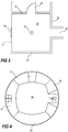
- a monitoring camera 10 is installed in the ceiling of a room 30, see Fig 3 .
- the room includes four walls 31-34, wherein wall 31 hold a door 36 for passage to an area next to the room, wall 32 present a passage into a corridor 38, and wall 34 hold a window 40.
- the monitoring camera 10 is set in an overview mode, i.e. the camera head is capturing an overview image of the monitored area, by capturing images through the wide angle lens, the setting of the camera that is shown in Fig 1 .
- a frame from a video sequence from the monitoring camera10 in overview mode may look like the image in Fig 4 in which all four walls 31-34 of the monitored room 30 is captured by the overview camera view, i.e. the entire room 30 is captured by the monitoring camera when in overview mode. Moreover, the image frame reveals that a person 42 is entering the room. This is probably even more evident from a video sequence including the image frame.
- the operator may simply indicate the person 42 or the area of the person in the overview image at a control station and the camera head of the monitoring camera is directed away from the wide angle lens 20 and towards the indicated area of the monitored room 30.
- the directing of the camera head 12 away from the wide angle lens 20 may alternatively be initiated in response to a detected motion in the overview image, detected by means of a motion detection process.
- the camera head 12 will be moved into a position similar to the position showed in Fig 2 , and will possibly capture an image 44 as the one presented in Fig 5 .
- the image captured by the camera head 12 may have a wider or narrower image view depending on the lens 18 on the camera head 12 and/or the zoom setting of this lens 18. Then, when the operator has finished studying the person the camera head 12 may be returned to capture images through the wide angle lens 20 and thereby be returned to the overview mode of the monitoring camera. Alternatively, if the directing of the camera head 12 away from the wide angle lens 20 was performed in response to motion detection in the overview image, then the camera head 12 may return to capturing images through the wide angle lens 20 in response to no motion being detected in the detailed view.
- the monitoring camera 10 includes an image sensor 50, an image processing unit 52, a general processing unit 54, a volatile memory 56, a non-volatile memory 58, a network interface 60, a camera position controller 61, a panning motor 62, a panning motor controller 64, a tilting motor 66, and a tilting motor controller 68. Further means and devices required in a camera in order to perform normal camera functionality and normal network activities are not described herein as these means and devices are well known to the person skilled in the art.
- the image sensor 50 may be any known image sensor able to capture light representing an image view and convert the light to electrical signals which then may be processed into digital images and or digital image streams by the image processing unit 52.
- the image sensor 50 may be arranged to capture visible light or infrared light, depending on the application of the camera.
- the image data from the image sensor 50 is sent to the image processing unit 52 via connection 70.
- the image processing unit 52 and the general processing unit 54 may be the same device, may be implemented as separate units on the same chip, or may be separate devices. Moreover, many functions described below as being performed in the image processing unit 52 may be performed in the general processing unit 54 and vice versa.
- the processing units 52, 54 are connected to the volatile memory 56 for use as a work memory via for instance a bus 72. Moreover, the volatile memory 56 may be used as temporary data storage for image data during processing of the image data and the volatile memory 56 may therefore be connected to the image sensor 50 as well.
- the non-volatile memory 58 may store program code required for the processing units 52, 54 to operate and may store settings and parameters that is to be preserved for a longer time period and even withstand power outages.
- the processing units 52, 54 are connected to the non-volatile memory 58 via, for instance, the bus 72.
- the network interface 60 includes an electrical interface to the network 74, which the monitoring camera is to be connected to. Further, the network interface 60 also includes all logic interface parts that are not implemented as being executed by the processing unit 54.
- the network 74 may be any known type of LAN (Local Area Network), WAN (Wide Area Network), or the Internet. The person skilled in the art is well aware of how to implement a network interface using any of a plurality of known implementations and protocols.
- the panning motor 62 and the tilting motor 66 are controlled by the processing 54 unit via each motor controller 64, 68.
- the motor controllers are arranged to convert instructions from the camera position controller 61 into electrical signals compatible with the motors.
- the camera position controller 61 may be implemented by means of code stored in memory 58 or by logical circuitry.
- the tilt motor 66 may be arranged within or very close to a panable/tiltable camera head 12 and the pan motor 62 are in many cases arranged further away from the camera head 12, in particular in the cases where the joint for panning is the second joint, counted from the camera head 12. Control messages for pan and tilt may be received via the network 74 and processed by the processing unit 54 before forwarded to the motor controllers 64, 68.
- the above described function of redirecting the camera head from capturing overview images to capturing detailed images of positions indicated in an image captured in overview mode may be implemented by transforming the coordinates of the indicated position within the overview image to pan and tilt angles for positioning the camera in detailed mode to capture an image of the indicated position.
- the pan angle, ⁇ and the tilt angle, ⁇ , may be calculated from the coordinates x, y, in the overview image, schematically depicted in Fig 7a , using the equations below.
- Distances dx and dy respectively, are the distances from the centre, 0,0, of the overview image to an indicated position, x, y within the boundary 102 of the overview image.
- the total view angle, ⁇ captured by the wide angle lens is a parameter used for approximating the tilt angle requested from indication of a point in the overview. The relations between these angles and coordinates are also showed in Figs 7a and 7b .
- the pan angle ⁇ is simply calculated by applying trigonometry to the Cartesian coordinates, see eq. 3.
- the tilt angle ⁇ according to this specific embodiment is an approximation in which the calculation approximates the features of the image captured as being positioned on a spherical surface 702, thus arriving at the equation eq. 2 in which the tilt angle ⁇ is calculated by applying the distance ratio of the distance d and the distance r to the total view angle ⁇ .
- the invention is not necessarily limited to this transformation scheme but any known transformation scheme may be used.
- FIGs 8a-b The resulting transformation from a system offering less quality transformations is illustrated in Figs 8a-b in which an overview image 802 and an detailed image 804 resulting from the selection of a point 806 in the overview image is showed. For instance, let us assume that the user selects the position 806 in the overview image depicting the features of a doorknob 808. The camera then change mode into the detailed mode and redirect the camera for capturing an image or video having the selected point 808 in the centre 810 of the frame.
- the transformation of positions between the two modes is not particularly precise resulting in an offset of e x and e y .
- An offset from requested positions, as described in the above example is worth adjusting for a couple of reasons. Examples of such reasons are that the offset is annoying for the user, the offset may result in a missed possibility of identifying a person who only is visible for a short amount of time, the offset may be troublesome in applications requiring masking, etc. In the example of applications requiring masking, e.g. of areas, objects, or persons, a high degree of precision is required in order not to mask a large portion outside the intended area, object or person and thereby blocking view of more information than requested.
- the offset, e x and e y may result from the act of mounting the wide angle lens 20 on the dome 14, the mounting of the dome 14 on the dome base 16, the mounting of the camera head 12 in the housing, etc.
- the camera assembly 10 requires tight mechanical tolerances in order not to introduce offset problems. For example, offset problems may occur if a mounting screw for any one of the dome, the camera, the wide angle lens, etc. is tightened a bit too hard.
- offset problems may occur if a mounting screw for any one of the dome, the camera, the wide angle lens, etc. is tightened a bit too hard.
- the optical axis 22 of the wide angle lens 20 and the optical axis 26 of the camera head 12 is offset, m off , when the camera head is arranged having its optical axis 26 coinciding with the rotational axis 24 for panning the camera head, see Fig 9 .
- the position in which the optical axis 26 of the camera head 12 is arranged to coincide with the rotational axis 24 of the camera head 12 is default position for capturing images through the wide angle lens 20 by means of the camera head 12.
- a slight offset of the wide angle lens may result in problems.
- This type of misalignment may also result in other problems than the problem of offset in between positions in an overview image and corresponding positions in a detailed view.
- Another problem may for instance be that the image sensor is not effectively utilised in view of useable pixels captured.
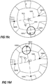
- FIG 10a One example of the image sensor not being effectively utilised is depicted in Fig 10a , where the image view projected onto the image sensor via the wide angle lens and the optics of the camera head is not centred on to the image sensor, indicated by distances e x and e y indicating the distance between the centre point 1002 of the projected image view and the centre point 1004 of the image sensor.
- the problem of the image sensor not being effectively utilised is addressed by calibrating the camera system.
- the calibration in this example includes the act of tilting the camera head 12 and moving the centre point 1002 of the projected image view to a position on an imaginary centre-line1006 dividing the image sensor in two halves, see Fig 10b .
- the projected image view is substantially circular due to the use of a wide angle lens that produces a circular image.
- the image sensor of this example is rectangular having a greater width, w, than height, h, and being wider than the diameter of the resulting projected circular image. Therefore the positioning of the projected image view in the direction of the width of the image sensor, i.e. along the x-axis, is not as critical as the positioning in the direction of the height of the image sensor.
- Figs 10a, 10b , and 11 One way of implementing this calibration feature is described below referring to Figs 10a, 10b , and 11 .
- the centre position along the y-axis of the projected image is determined but not necessary the centre position along the x-axis, because we only use the position along the y-axis for the adjustments.
- the position along the x-axis is required as well as the position along the y-axis.
- One way of determining the centre position is by using edge detection and a Standard Hough Transform arranged for finding parameters of a circle.
- the circle being represented by the edge of the image projection and the image projection being substantially circular if the camera is equipped with a lens generating circular images.
- the value of n is according to one example three. The value n is defining how many times the repositioning and checking of the camera head is allowed to be performed.
- n may be any number as long as it is small enough not to result in a perception of deteriorated performance.
- step 1114 If the check in step 1114 is false, the camera head is tilted based on the offset of between the centre CCy of the projected image along the y-axis and the centre of the image sensor along the y-axis, step 1116.
- step 1114 If the check in step 1114 is true then the position of the camera head is stored in memory in order to be used as the position to return the camera head to when entering overview mode, step 1120, i.e. the overview mode coordinates or angles are set for the camera head. Then, when the overview position for the camera head has been determined the calibration process for positioning of the camera head in overview mode is concluded.
- the centre of the projected image is found using a Hough Transform and the projected image is substantially circular. Further information of the Hough Transform may be found in " Computer Vision", by Shapiro, Linda and Stockman, Prentice-Hall, Inc. 2001 .
- the boundary of the image projection have to be determined. This may be performed using any standard edge detection algorithm.
- the Hough Transform is applied to the detected edge.
- the processing using the Hough Transform may be speeded up by defining a limited range of possible circle radiuses for the analysing by means of the Hough transform.
- the radius used in the Hough transform is in the range of 0.25 - 0.35 times the width of the image sensor.
- the radiuses is selected in the range of 320pixels - 448pixels..
- the radiuses may be selected from the range of 0.2921875 - 0.3125 times the width of the image sensor in pixels. For a system having a sensor that has a width of 1280 pixels the radiuses are selected in the range of 374pixels - 400pixels.
- the above process of centring the image projection on the images sensor may be part of a calibration scheme for decreasing the offset between a selected position in the overview image and the centre position in the detailed image view, see discussion relating to Fig 8a-b .
- a method, step 1200, for calibrating a pan tilt enabled camera may comprise acts described below.
- the process is initiated with the camera in overview mode and the process captures an overview image when camera is in overview mode, step 1202.
- the captured overview image is displayed and a pattern including indicators of at least three suggested selection areas is arranged as an overlay on the overview image, step 1204.
- the orientation of the overlay may then be adjusted by the operator in order to have as many distinguishing features as possible within a selection area indicated by the overlay, step 1206.
- the adjustment of the orientation of the overlay may include rotation of the overlay, e.g.
- repositioning the suggested selection areas by uniformly moving them closer to or further away from the centre point of the image view.
- This reposition operation and the rotation operation may be performed as a drag and drop operation on the overlay.
- a point at a feature in one of the at least three suggested selection areas is selected, step 1208.
- the coordinates of the selected point is transformed into a pan angle and a tilt angle, step 1210.
- step 1212 Thereafter the camera is panned and tilted in accordance with said pan angle and said tilt angle, entering the camera into detailed mode, and detailed image is captured when camera is in detailed mode after panning and tilting in accordance with said pan angle and said tilt angle is completed, step 1212.
- the transition to detailed mode seldom results in the selected feature occurring in the centre of the captured image in the detailed image view.
- the operator are now to manually adjust pan angle and tilt angle until the camera presents the point of the feature selected in the overview image substantially in the centre of the image captured in detailed mode, step 1214.
- the camera is capturing images frequently during this panning and tilting in order to present the result of the panning and tilting to the operator.
- Information indicating the difference between the manually adjusted pan angle and tilt angle and the pan angle and the tilt angle resulting from the transforming of the position of the feature is now saved, 1216. This information is saved for later use.
- the steps of selecting features and registering the error in the transition from overview mode to detailed mode is then repeated for at least two further selection areas, i.e.
- n 3 in step 1218.
- the value of n may be any number equal to or greater than three. The value of n should however not be too large, because then the calibration will be quite time consuming. In order to balance accuracy and speed the value of n may be in the range of 4-10.
- the process estimates a function f ⁇ err ( ⁇ calc ) , representing a pan error, in which ⁇ calc is the pan angle directly transformed from the overview coordinates, and a function f ⁇ err ( ⁇ calc ) , representing a tilt error, which also is depending on the pan angle ⁇ calc .
- These functions f ⁇ err ( ⁇ calc ) and f ⁇ err ( ⁇ calc ) represent the errors based on the saved information, step 1220, and the calibration process is ended.
- the estimated function may now be used for compensating in transformations between positions in the overview mode and pan and tilt angles in detailed mode, i.e. said function may be applied on operations including transforming coordinates from the overview image to pan and tilt angles.
- Fig 13 an example of said overlay 1300 including indicators 1302a-d of suggested areas is shown.
- the overlay is shown positioned in an overview image view, depicted with dashed lines, in order to indicate its relation to the overview image.
- the main function of the overlay is to support the operator performing the calibration by facilitate uniformly selection of calibration points.
- the overlay is rotatable, see Fig 14 . By enable rotation of the overlay it is possible for the operator to keep the uniform distribution of the selection areas while trying to fit easily identifiable features to select as calibration points.
- the indicators of suggested areas 1302a-d are rotated around the centre point of the image view in real time in order to make it easy for the operator to see when features that are easily identifiable are present in all or at least in most of the indicators of suggested areas.
- the selection of calibration points that are uniformly distributed around the centre point of the overview image makes the estimation of the error function more precise than if the points are positioned towards one side of the overview image.
- the number of suggested selection areas are four in Figs 13-14 , however as discussed above the number of selection areas may vary.
- the process of selecting satisfactory points for use in calibration is performed by means of a dynamically adapting selection overlay.
- the process of this dynamic selection overlay comprises an initial presentation of an image captured in overview mode, step 1502, and then displaying this image 1300 and added thereon an overlay presenting a suggested selection area 1602a-d, step 1504.
- the image captured by the camera is showed as dashed lines in order to facilitate distinguishing between the overlay and the captured image in the figures. For the first selection it is not necessary to present any suggested selection area because the following recommended selections will be based on the position in the overview image of the actual selection.
- the user is then selecting a specific calibration position 1604a-d within the presented overview image, step 1508.
- the selected calibration position is advantageously a position showing a clearly distinguishing feature for facilitating identification of the feature when in detailed mode.
- These position coordinates are then transformed to pan and tilt angles in accordance with equations 1-3, step 1510, for use by the camera in detailed mode.
- the camera head is panned and tilted to said pan and tilt angles in detailed mode and captures a detailed image view, step 1512.
- This detailed image view is studied by an operator who makes necessary adjustments for centring of the selected feature in the detailed view, step 1514.
- the difference between the transformed centre position and the centre position after adjustment by the operator is stored in memory for later use in estimating error functions, step 1516.
- the distribution in circumferential direction of selected positions is evaluated. This is performed by identifying an angle ⁇ between radiuses from the centre to two circumferentially adjacent selected positions. When only one position is selected the angle ⁇ will be 360 degrees. The greatest angle ⁇ max between adjacent selected positions is identified, step 1518. For the first selected position this angle is 360 degrees. If ⁇ max is smaller than a predetermined threshold value ⁇ thresh ,step 1520, then the process is deemed to have enough data to estimate error functions and the process ends by estimating the error function representing the saved differences, step 1522.
- step 1520 if ⁇ max is not smaller than said predetermined threshold ⁇ thresh value, step 1520, then a suggested selection area is positioned between, in circumferential direction, the two positions presenting the largest angle ⁇ max between them.
- the new suggested selection area is positioned substantially at an angle of ⁇ max /2 from any one of the two adjacent positions. Then the process returns to step 1508 for selection of another calibration position.
- Figs 16a-d shows four consecutive selection loops relating to the process described in Fig 15 .
- Fig 16a shows the initial suggested selection area 1602a and the initial selected calibration position 1604a selected in this first selection loop.
- the largest angle ⁇ max after this initial selection of a calibration position is 360 degrees.
- the lines 1606 and 1608 are only a helplines later used in order to facilitate the description of angles and, thus, these lines do not have to be included in the interface of an implementation of the invention.
- Fig 16b the selection view is shown when the selection process has returned for selection of a second calibration process and positioned a new suggested selection area 1602b at an angle ⁇ max /2 from the previously selected calibration position 1604a, see the angle between helplines 1606 and 1610.
- the suggested selection area 1602b is positioned 180 degrees from the previous calibration position 1604a as there was only one previous selection position 1604a.
- the operator selects a new calibration position 1604b over a suitable feature.
- the suggested selection areas 1602a-d are not necessary the only areas possible to select calibration positions within but rather indicates suitable areas for selecting calibration positions.
- the selection process continues and eventually presents a new suggested selection area 1602c for the operator.
- the position of this new suggested selection area 1602c is once more calculated as half the angle ⁇ max /2 of the largest angle ⁇ max between two circumferentially neighbouring selected calibration positions.
- the largest angle ⁇ max is found between the calibration positions 1604a and 1604b and is a fraction larger than 180 degrees and, thus, the suggested selection area 1602c is arranged substantially 90 degrees from any of the lines 1606 or 1612.
- a new calibration position 1604c is selected by the operator and the process loops once more.
- next suggested selection area 1602d is then positioned substantially at an angle marginally less than 90 degrees from the lines 1606 or 1612 forming the largest angle ⁇ max .
- the operator select the next calibration position 1604d and the process continues, unless this is the last calibration position to be recorded.
- the error functions f ⁇ err ( ⁇ calc ) and f ⁇ err ( ⁇ calc ) may be estimated by a trigonometric function or a polynomial.
- the advantage of using a polynomial estimation is that a Linear Least Square Estimation (LLSE) may be used to find the coefficients of the functions. How to estimate a polynomial function using LLSE is well known to the person skilled in the art.
- the resulting pan-tilt position i.e. the one determined by adjusting using the error function, is of substantially higher accuracy than a position calculated without using the error compensation.
- Transformations from a pan-tilt position ⁇ , ⁇ to an overview position x, y may also be necessary.
- One case in which such transformation may be of interest is if an object in the detailed view has to be masked and the operator returns the camera to the overview mode.
- the masked object should be masked in the overview mode as well as in the detailed mode.
- the position in the detailed mode has to be transformed to a position in the overview.
- the transformation from pan-tilt positions ⁇ , ⁇ to overview positions x, y is based on equations inverting the transformation described in relation to equations 1-3.
- the transformation includes calculating the distance d in the overview, see Figs 7a-b and eq. 9.
- the distance d is approximated as having the same relation to the radius of the overview image as the relation between tilt angle ⁇ and the total view angle ⁇ .
- the dx and dy distances may be calculated using basic trigonometry, see eq. 10 and eq. 11, in which ⁇ is the pan angle.
- the process further adjusts for the coordinates of the centre point x c , y c , used as reference for the pan angle ⁇ , for the distance d and for dx and dy.
- this transform as well as in the transform for transformation from overview to detailed view, misalignment errors are present and therefore error functions for x and y, respectively, has to be determined. In one particular embodiment these functions are estimated from substantially the same calibration process and data as described above.
- the calibration process may be identical to any of the calibration processes described in connection with Fig 12 or Fig 15 with the addition of detecting and recording a position error in transformation to the overview coordinates using the identical calibration inputs already used in any of the processes described in Figs 12 or 15 for the detection and recordation of the transformation error from an overview position to a pan-tilt position in a detailed view.
- the detection of the position error includes applying transformation equations to the pan-tilt position resulting from the operator's adjustments when aligning the centre of the detailed view with the presently selected feature for. The resulting coordinates in the Cartesian coordinate system of the overview, i.e.
- x t , y t are then compared with the coordinates, x, y, from the original selection of the feature. These coordinates of the original selection are thus the true coordinates in the overview image of the feature that the operator adjusted to the centre of the detailed view and these coordinates has already been registered.
- the error functions may be estimated from the error data using the same methods as discussed above in relation to the estimation of the estimation of error functions for the transformation from overview mode to detailed mode.
- the error functions f x ( ⁇ ), f y ( ⁇ ), have been estimated based on pan angle dependency not taking the tilt angle into account.
- the tilt angle had substantially no effect on the error and therefore it was not necessary to consider the tilt-angle.
- the error functions may be based on other variables, if a specific implementation so requires.
- this transformation from the detailed mode to the overview mode may be used in correctly positioning masks.
- masks for the pan-tilt cameras are often defined in pan-tilt angles and by introducing a more precise transformation method theses masks may simply be recalculated for the overview instead of being re-entered for the overview coordinates and thus facilitating the setting up of the monitoring camera.
- Another use of this transformation is that it enables improvements to the interface. For example, when the camera is in detailed mode, depicted in Fig 17 , a marker 1700 indicating the position of the detailed image view may be simultaneously displayed on the overview . In such an application the overview may be displayed together with the detailed view in order to facilitate the understanding of the orientation of the camera.
- the position of the centre point of the detailed view is continuously transformed into overview coordinates which are used for positioning the marker in the overview.
- the operator using this type of system may quickly identify where the monitoring camera is monitoring and may thus easily inform others about the whereabouts of specific activities.
- Providing a detailed view and an overview in the same operators view are not necessary restricted to use of a camera described in this application, but, according to the invention, is used in a system using two separate cameras, one for the detailed view and another for the overview.
- it may be used in a system using a standard pan-tilt-zoom camera in combination with an overview image being stitched from a plurality of images captured by the camera.
- the stitched overview image may be updated when new image information is available.
- the overview image may according to one example be a static image when a detailed view is presented, but according to the invention the overview may be a live image even when the detailed view is presented live.
Landscapes
- Engineering & Computer Science (AREA)
- Multimedia (AREA)
- Signal Processing (AREA)
- Health & Medical Sciences (AREA)
- Biomedical Technology (AREA)
- General Health & Medical Sciences (AREA)
- Computer Vision & Pattern Recognition (AREA)
- Physics & Mathematics (AREA)
- General Physics & Mathematics (AREA)
- Theoretical Computer Science (AREA)
- Studio Devices (AREA)
Description
- The present invention relates to a method for calibrating a camera and in particular a method for calibrating a pan-tilt enabled camera system in order to account for misalignments in the camera system
- It is often difficult to move camera heads, e.g. pan and tilt enabled camera heads, with precision to a general position in a range of accessible pan tilt positions. Additional problems with the precision arise when the camera is to provide a view of an interpreted or transformed selection selected in a visual interface.
- The precision becomes even worse in a system where you have a camera head acquiring images through a lens, e.g. a wide angle lens, not mounted on the camera head but rather fixedly attached to a support structure of the camera head. Hence in these cases the precision of the mounting of said lens and the support structure it is attached to is critical. In addition to the problem of mounting said lens with precision the camera may be shipped not having the lens or the support structure mounted together with the camera head and in such case the precision mounting has to be performed in the field. Accordingly, these types of systems often present problems with precision in positioning.
- One object of the present invention is to improve the precision in positioning a camera for acquiring a desired image view.
- The object is achieved by means of a method according to
claim 1. Further embodiments of the invention are presented in the dependent claims. - A further scope of applicability of the present invention will become apparent from the detailed description given below. However, it should be understood that the detailed description and specific examples, while indicating preferred embodiments of the invention, are given by way of illustration only, since various changes and modifications within the scope of the invention will become apparent to those skilled in the art from this detailed description. Hence, it is to be understood that this invention is not limited to the particular component parts of the device described or steps of the methods described as such device and method may vary. It is also to be understood that the terminology used herein is for purpose of describing particular embodiments only, and is not intended to be limiting. It must be noted that, as used in the specification and the appended claim, the articles "a," "an," "the," and "said" are intended to mean that there are one or more of the elements unless the context clearly dictates otherwise. Thus, for example, reference to "a sensor" or "the sensor" may include several sensors, and the like. Furthermore, the word "comprising" does not exclude other elements or steps.
- Other features and advantages of the present invention will become apparent from the following detailed description of embodiments and examples, with reference to the accompanying drawings, in which
-
Fig 1 is a schematic side view of a monitoring camera implementing one example, -
Fig 2 is the same side view as inFig 1 with the difference that the camera head of the monitoring camera is tilted, -
Fig 3 is a schematic overview of an example room in which a monitoring camera according to one embodiment of the invention is fictionally installed, -
Fig 4 is an example overview image from the monitoring camera in the example room ofFig 3 capturing images through a wide angle lens as inFig 1 , -
Fig 5 is an example of a detailed view from the monitoring camera in example room ofFig 3 capturing images through the dome glass as depicted inFig 2 , -
Fig 6 is a schematic block diagram of a camera head according to one example, -
Fig 7a-b is diagrams showing the relations between the camera head, positions in overview image, and pan-tilt angles for the camera head, -
Fig 8a shows an overview image and a selected position in said overview image, -
Fig 8b shows a possible detailed view resulting from the camera transitioning from the overview mode to a detailed view of the selected position, -
Fig 9 shows a schematic diagram of a camera in which the camera head and the wide angle lens is not aligned properly, -
Fig 10a shows an overview image projected to the image sensor in a camera where the camera head and the wide angle lens is not properly aligned, -
Fig 10b shows the overview image projected on the image sensor after the camera head and the wide angle lens has been aligned according to one example, -
Fig 11 is a flowchart showing a process of centring the projected overview image onto the image sensor, -
Fig 12 is a flowchart showing a process of calibrating a transfer function from a position in an overview image to a pan and tilt position for a detailed view, -
Fig 13 schematically depicts an overlay for facilitating selection of calibration positions that may be used in the process ofFig 12 , -
Fig 14 schematically indicates a turning function of the overlay ofFig 13 , -
Fig 15 is a flowchart is a flowchart showing an alternative process of calibrating a transfer function from a position in an overview image to a pan and tilt position for a detailed view, -
Fig 16a-c shows the overview image and a selection overlay at different stages of the process described in connection withFig 15 , and -
Fig 17 is showing a detailed view incorporating an overview image according to one embodiment of the invention. - Further, in the figures like reference characters designate like or corresponding parts throughout the several figures.
- The present invention relates to calibration of the positioning of a camera head in a monitoring camera. Referring to
Fig 1 , according to one example themonitoring camera 10 is a dome camera including acamera head 12, atransparent dome cover 14, and adome base 16. Thecamera head 12 is enabled to pan and tilt by means of electronically controlled motors, not shown. Thecamera head 12 may be any known camera head that is enabled to pan and tilt. Further, thecamera head 12 includes alens 18. Thelens 18 is arranged to focus light representing a scene to be captured by thecamera 10 onto an image sensor in thecamera head 12. The viewing angle of the captured image may be fixed or variable. Variable viewing angle may be accomplished by having a zoom enabledlens 18. In case of a fixed viewing angle lens the selection of the viewing angle may differ between different applications of the camera. - The dome camera further comprises a
wide angle lens 20 mounted on thetransparent dome cover 14 and extending from thedome cover 14 and away from thecamera head 12. Thewide angle lens 20 is mounted in a direction making theoptical axis 22 of the wide angle lens substantially coincide with arotational axis 24 around which thecamera head 12 is turned during panning, hereinafter referred to aspanning axis 24. The viewing angle of thewide angle lens 20 is wider than the viewing angle of thelens 18 in thecamera head 12. In one example the viewing angle of thewide angle lens 20 is substantially wider than the viewing angle of thelens 18 of thecamera head 12. The view angle of the wide angle lens may be more than 180 degrees. However, depending on the application the viewing angle may be less or more. The angle should at least be selected to provide a reasonable overview image. - Accordingly, the
wide angle lens 20 is mounted so that theoptical axis 26 of thecamera head 12 is aligned with theoptical axis 22 of thewide angle lens 20 when thecamera head 12 is directed for capturing an image through thewide angle lens 20. - Due to the positioning of the
wide angle lens 20 and the fact that thecamera head 12 is moveable it is possible to capture overview images through thewide angle lens 20 as depicted inFig 1 and when something interesting is spotted or detected in the overview image it is possible to investigate in more detail by simply moving thecamera head 12 away from thewide angle lens 20 and directing it towards the interesting event or feature and capturing images through the dome cover. InFig 2 the camera is shown in a position for capturing the images through the dome cover in order to get a more detailed view and not through thewide angle lens 20. - In one example the viewing angle or the focal length of the
lens 18 of thecamera head 12 is selected so that the images captured by thecamera head 12, when not captured through thewide angle lens 20, is adequate for providing relevant surveillance information. Examples of relevant surveillance information may for instance be the registration number of a car, an identifiable face of a person, detailed progress of an event, etc. The viewing angle of thewide angle lens 20 may be selected so that thecamera head 12 will capture an image view of at least the floor of an entire room in which the monitoring camera is installed when directed to capture images through thewide angle lens 20. Alternatively, the viewing angle of thewide angle lens 20 is selected so that thecamera head 12 will capture an overview image of the monitored area when thecamera head 12 is directed to capture images through thewide angle lens 20. Then an operator or an image analysis process may identify events or features of interest in the overview and redirect thecamera head 12 for direct capture of the scene including the event or feature of interest. "Direct capture" in the above sentence should be understood as capturing an image by means of thecamera head 12 when not directed to capture images through thewide angle lens 20. - In order to facilitate the understanding of the function of the camera an example scenario will be described below. In the example scenario a
monitoring camera 10 is installed in the ceiling of aroom 30, seeFig 3 . The room includes four walls 31-34, whereinwall 31 hold adoor 36 for passage to an area next to the room,wall 32 present a passage into acorridor 38, andwall 34 hold awindow 40. Let us assume that themonitoring camera 10 is set in an overview mode, i.e. the camera head is capturing an overview image of the monitored area, by capturing images through the wide angle lens, the setting of the camera that is shown inFig 1 . A frame from a video sequence from the monitoring camera10 in overview mode may look like the image inFig 4 in which all four walls 31-34 of the monitoredroom 30 is captured by the overview camera view, i.e. theentire room 30 is captured by the monitoring camera when in overview mode. Moreover, the image frame reveals that aperson 42 is entering the room. This is probably even more evident from a video sequence including the image frame. If an operator having access to the imagery of thismonitoring camera 10, and having authority to control themonitoring camera 10, finds thisperson 42 interesting and would like to get a more detailed image of theperson 42, then the operator may simply indicate theperson 42 or the area of the person in the overview image at a control station and the camera head of the monitoring camera is directed away from thewide angle lens 20 and towards the indicated area of the monitoredroom 30. The directing of thecamera head 12 away from thewide angle lens 20 may alternatively be initiated in response to a detected motion in the overview image, detected by means of a motion detection process. Hence, thecamera head 12 will be moved into a position similar to the position showed inFig 2 , and will possibly capture animage 44 as the one presented inFig 5 . The image captured by thecamera head 12 may have a wider or narrower image view depending on thelens 18 on thecamera head 12 and/or the zoom setting of thislens 18. Then, when the operator has finished studying the person thecamera head 12 may be returned to capture images through thewide angle lens 20 and thereby be returned to the overview mode of the monitoring camera. Alternatively, if the directing of thecamera head 12 away from thewide angle lens 20 was performed in response to motion detection in the overview image, then thecamera head 12 may return to capturing images through thewide angle lens 20 in response to no motion being detected in the detailed view. - According to one example, see
Fig 6 , the monitoringcamera 10 includes animage sensor 50, animage processing unit 52, ageneral processing unit 54, avolatile memory 56, anon-volatile memory 58, anetwork interface 60, acamera position controller 61, a panningmotor 62, a panningmotor controller 64, a tiltingmotor 66, and a tiltingmotor controller 68. Further means and devices required in a camera in order to perform normal camera functionality and normal network activities are not described herein as these means and devices are well known to the person skilled in the art. - The
image sensor 50 may be any known image sensor able to capture light representing an image view and convert the light to electrical signals which then may be processed into digital images and or digital image streams by theimage processing unit 52. Thus, theimage sensor 50 may be arranged to capture visible light or infrared light, depending on the application of the camera. The image data from theimage sensor 50 is sent to theimage processing unit 52 viaconnection 70. Theimage processing unit 52 and thegeneral processing unit 54 may be the same device, may be implemented as separate units on the same chip, or may be separate devices. Moreover, many functions described below as being performed in theimage processing unit 52 may be performed in thegeneral processing unit 54 and vice versa. - The
processing units volatile memory 56 for use as a work memory via for instance abus 72. Moreover, thevolatile memory 56 may be used as temporary data storage for image data during processing of the image data and thevolatile memory 56 may therefore be connected to theimage sensor 50 as well. Thenon-volatile memory 58 may store program code required for theprocessing units processing units non-volatile memory 58 via, for instance, thebus 72. - The
network interface 60 includes an electrical interface to thenetwork 74, which the monitoring camera is to be connected to. Further, thenetwork interface 60 also includes all logic interface parts that are not implemented as being executed by theprocessing unit 54. Thenetwork 74 may be any known type of LAN (Local Area Network), WAN (Wide Area Network), or the Internet. The person skilled in the art is well aware of how to implement a network interface using any of a plurality of known implementations and protocols. - The panning
motor 62 and the tiltingmotor 66 are controlled by theprocessing 54 unit via eachmotor controller camera position controller 61 into electrical signals compatible with the motors. Thecamera position controller 61 may be implemented by means of code stored inmemory 58 or by logical circuitry. Thetilt motor 66 may be arranged within or very close to a panable/tiltable camera head 12 and thepan motor 62 are in many cases arranged further away from thecamera head 12, in particular in the cases where the joint for panning is the second joint, counted from thecamera head 12. Control messages for pan and tilt may be received via thenetwork 74 and processed by theprocessing unit 54 before forwarded to themotor controllers - Other implementations of the
monitoring camera 10 are evident to the person skilled in the art. - The above described function of redirecting the camera head from capturing overview images to capturing detailed images of positions indicated in an image captured in overview mode may be implemented by transforming the coordinates of the indicated position within the overview image to pan and tilt angles for positioning the camera in detailed mode to capture an image of the indicated position.
- Now referring to
Figs 7a and 7b , the pan angle, ψ, and the tilt angle, ϕ, may be calculated from the coordinates x, y, in the overview image, schematically depicted inFig 7a , using the equations below. Distances dx and dy, respectively, are the distances from the centre, 0,0, of the overview image to an indicated position, x, y within theboundary 102 of the overview image. Moreover, referring toFig 7b , showing a side view of a site havingmonitoring camera 10 mounted in the ceiling, the total view angle, θ, captured by the wide angle lens is a parameter used for approximating the tilt angle requested from indication of a point in the overview. The relations between these angles and coordinates are also showed inFigs 7a and 7b .


- Using these equations the pan angle ψ is simply calculated by applying trigonometry to the Cartesian coordinates, see eq. 3. The tilt angle ϕ according to this specific embodiment is an approximation in which the calculation approximates the features of the image captured as being positioned on a
spherical surface 702, thus arriving at the equation eq. 2 in which the tilt angle ϕ is calculated by applying the distance ratio of the distance d and the distance r to the total view angle θ. The invention is not necessarily limited to this transformation scheme but any known transformation scheme may be used. - Depending on the application of the camera the level of precision required of the transformation may vary. However, even in applications not requiring very high precision a user will expect the point selected in the overview to appear quite close to the centre of the image in the detailed view. The resulting transformation from a system offering less quality transformations is illustrated in
Figs 8a-b in which anoverview image 802 and andetailed image 804 resulting from the selection of apoint 806 in the overview image is showed. For instance, let us assume that the user selects theposition 806 in the overview image depicting the features of adoorknob 808. The camera then change mode into the detailed mode and redirect the camera for capturing an image or video having the selectedpoint 808 in thecentre 810 of the frame. However, in this example the transformation of positions between the two modes is not particularly precise resulting in an offset of ex and ey. An offset from requested positions, as described in the above example, is worth adjusting for a couple of reasons. Examples of such reasons are that the offset is annoying for the user, the offset may result in a missed possibility of identifying a person who only is visible for a short amount of time, the offset may be troublesome in applications requiring masking, etc. In the example of applications requiring masking, e.g. of areas, objects, or persons, a high degree of precision is required in order not to mask a large portion outside the intended area, object or person and thereby blocking view of more information than requested. - The offset, ex and ey, may result from the act of mounting the
wide angle lens 20 on thedome 14, the mounting of thedome 14 on thedome base 16, the mounting of thecamera head 12 in the housing, etc. Thecamera assembly 10 requires tight mechanical tolerances in order not to introduce offset problems. For example, offset problems may occur if a mounting screw for any one of the dome, the camera, the wide angle lens, etc. is tightened a bit too hard. Hence one common problem is that theoptical axis 22 of thewide angle lens 20 and theoptical axis 26 of thecamera head 12 is offset, moff, when the camera head is arranged having itsoptical axis 26 coinciding with therotational axis 24 for panning the camera head, seeFig 9 . The position in which theoptical axis 26 of thecamera head 12 is arranged to coincide with therotational axis 24 of thecamera head 12 is default position for capturing images through thewide angle lens 20 by means of thecamera head 12. However, as evident fromFig 9 , a slight offset of the wide angle lens may result in problems. This type of misalignment may also result in other problems than the problem of offset in between positions in an overview image and corresponding positions in a detailed view. Another problem may for instance be that the image sensor is not effectively utilised in view of useable pixels captured. - One example of the image sensor not being effectively utilised is depicted in
Fig 10a , where the image view projected onto the image sensor via the wide angle lens and the optics of the camera head is not centred on to the image sensor, indicated by distances ex and ey indicating the distance between thecentre point 1002 of the projected image view and thecentre point 1004 of the image sensor. - According to one example the problem of the image sensor not being effectively utilised is addressed by calibrating the camera system. The calibration in this example includes the act of tilting the
camera head 12 and moving thecentre point 1002 of the projected image view to a position on an imaginary centre-line1006 dividing the image sensor in two halves, seeFig 10b . In this example the projected image view is substantially circular due to the use of a wide angle lens that produces a circular image. The image sensor of this example is rectangular having a greater width, w, than height, h, and being wider than the diameter of the resulting projected circular image. Therefore the positioning of the projected image view in the direction of the width of the image sensor, i.e. along the x-axis, is not as critical as the positioning in the direction of the height of the image sensor. One way of implementing this calibration feature is described below referring toFigs 10a, 10b , and11 . - The process of calibrating the
camera 10 in order to effectively utilising the image sensor by centring the overview is initiated,process 1100, and thecamera head 12 is tilted into theoptical path 22 of thewide angle lens 20,step 1102, and is thus positioned for capturing images in overview mode. Then a counter C is reset to e.g. zero, C=0,step 1104. The idea behind the counter is to count the number of times the repositioning procedure below has been performed in order to limit the number of times this procedure is performed. An image is captured through the wide angle lens,step 1106, and the position CCy of the centre of the captured image is determined,step 1108. In this particular embodiment the centre position along the y-axis of the projected image is determined but not necessary the centre position along the x-axis, because we only use the position along the y-axis for the adjustments. However, there may be specific embodiments in which the position along the x-axis is required as well as the position along the y-axis. One way of determining the centre position is by using edge detection and a Standard Hough Transform arranged for finding parameters of a circle. The circle being represented by the edge of the image projection and the image projection being substantially circular if the camera is equipped with a lens generating circular images. - This centre CCy of the projected image is then related to the centre of the image censor CSy, also along the y-axis, and the process checks,
step 1112, if the centre CCy of the projected image along the y-axis is substantially centred on the image sensor, i.e. if CCy=CSy ± tolerance. If the centre CCy of the projected image is determined to correspond the centre CSy of the image sensor in the y-direction or if the counter C counting the number of times this check and repositioning of the camera head has been performed n times. The value of n is according to one example three. The value n is defining how many times the repositioning and checking of the camera head is allowed to be performed. One reason for this parameter is to avoid that the system get stuck in a loop if for instance the system for some reason is not able to determine the centre. Hence, the value of n may be any number as long as it is small enough not to result in a perception of deteriorated performance. - If the check in
step 1114 is false, the camera head is tilted based on the offset of between the centre CCy of the projected image along the y-axis and the centre of the image sensor along the y-axis,step 1116. According to one example an angle αtilterr that thecamera head 12 is to be tilted is calculated based on equation 4 below:
- αtilterr : the angle that the camera head should be tilted
- βtotch : the total viewing angle from camera head alone
- ey : distance from the centre CSy of the image sensor to centre of captured circular image CCy
- h : height of image sensor
- If the check in
step 1114 is true then the position of the camera head is stored in memory in order to be used as the position to return the camera head to when entering overview mode,step 1120, i.e. the overview mode coordinates or angles are set for the camera head. Then, when the overview position for the camera head has been determined the calibration process for positioning of the camera head in overview mode is concluded. - According to one example the centre of the projected image is found using a Hough Transform and the projected image is substantially circular. Further information of the Hough Transform may be found in "Computer Vision", by Shapiro, Linda and Stockman, Prentice-Hall, Inc. 2001. In order to apply the Hough Transform for finding the parameters of the circle represented by the image projection the boundary of the image projection have to be determined. This may be performed using any standard edge detection algorithm. When the edge of the projected image has been detected the Hough Transform is applied to the detected edge. The processing using the Hough Transform may be speeded up by defining a limited range of possible circle radiuses for the analysing by means of the Hough transform. This may be achieved as a result of it being possible to have a quite accurate idea of the size of the circle shaped image projection. In one particular example the radius used in the Hough transform is in the range of 0.25 - 0.35 times the width of the image sensor. For a system having a sensor that has a width of 1280 pixels the radiuses is selected in the range of 320pixels - 448pixels..
- In order to speed up the process even more and still get reliable results the radiuses may be selected from the range of 0.2921875 - 0.3125 times the width of the image sensor in pixels. For a system having a sensor that has a width of 1280 pixels the radiuses are selected in the range of 374pixels - 400pixels.
- The above process of centring the image projection on the images sensor may be part of a calibration scheme for decreasing the offset between a selected position in the overview image and the centre position in the detailed image view, see discussion relating to
Fig 8a-b . - A calibration scheme for decreasing said offset is described in the flowchart of
Fig 12 . Accordingly according to one embodiment a method,step 1200, for calibrating a pan tilt enabled camera may comprise acts described below. The process is initiated with the camera in overview mode and the process captures an overview image when camera is in overview mode,step 1202. The captured overview image is displayed and a pattern including indicators of at least three suggested selection areas is arranged as an overlay on the overview image,step 1204. The orientation of the overlay may then be adjusted by the operator in order to have as many distinguishing features as possible within a selection area indicated by the overlay,step 1206. The adjustment of the orientation of the overlay may include rotation of the overlay, e.g. around a centre point of the image view, repositioning the suggested selection areas by uniformly moving them closer to or further away from the centre point of the image view. This reposition operation and the rotation operation may be performed as a drag and drop operation on the overlay. Then, a point at a feature in one of the at least three suggested selection areas is selected,step 1208. The coordinates of the selected point is transformed into a pan angle and a tilt angle,step 1210. - Thereafter the camera is panned and tilted in accordance with said pan angle and said tilt angle, entering the camera into detailed mode, and detailed image is captured when camera is in detailed mode after panning and tilting in accordance with said pan angle and said tilt angle is completed,
step 1212. - In the system not calibrated for transition errors, the transition to detailed mode seldom results in the selected feature occurring in the centre of the captured image in the detailed image view. The operator are now to manually adjust pan angle and tilt angle until the camera presents the point of the feature selected in the overview image substantially in the centre of the image captured in detailed mode,
step 1214. The camera is capturing images frequently during this panning and tilting in order to present the result of the panning and tilting to the operator. Information indicating the difference between the manually adjusted pan angle and tilt angle and the pan angle and the tilt angle resulting from the transforming of the position of the feature is now saved, 1216. This information is saved for later use. The steps of selecting features and registering the error in the transition from overview mode to detailed mode is then repeated for at least two further selection areas, i.e. n=3 instep 1218. The value of n may be any number equal to or greater than three. The value of n should however not be too large, because then the calibration will be quite time consuming. In order to balance accuracy and speed the value of n may be in the range of 4-10. - When steps 1208-1216 has been performed n times, then the process estimates a function fψerr(ψcalc), representing a pan error, in which ψ calc is the pan angle directly transformed from the overview coordinates, and a function fϕerr(ψcalc), representing a tilt error, which also is depending on the pan angle ψcalc. These functions fψerr(ψcalc)and fϕerr(ψcalc) represent the errors based on the saved information,
step 1220, and the calibration process is ended. The estimated function may now be used for compensating in transformations between positions in the overview mode and pan and tilt angles in detailed mode, i.e. said function may be applied on operations including transforming coordinates from the overview image to pan and tilt angles. - In
Fig 13 an example of saidoverlay 1300 includingindicators 1302a-d of suggested areas is shown. The overlay is shown positioned in an overview image view, depicted with dashed lines, in order to indicate its relation to the overview image. The main function of the overlay is to support the operator performing the calibration by facilitate uniformly selection of calibration points. In order to further facilitate the identification of selected points when the camera is directed towards the selected point in detailed view, the overlay is rotatable, seeFig 14 . By enable rotation of the overlay it is possible for the operator to keep the uniform distribution of the selection areas while trying to fit easily identifiable features to select as calibration points. As seen in the overview image ofFig 14 the indicators of suggestedareas 1302a-d are rotated around the centre point of the image view in real time in order to make it easy for the operator to see when features that are easily identifiable are present in all or at least in most of the indicators of suggested areas. The selection of calibration points that are uniformly distributed around the centre point of the overview image makes the estimation of the error function more precise than if the points are positioned towards one side of the overview image. The number of suggested selection areas are four inFigs 13-14 , however as discussed above the number of selection areas may vary. - According to another embodiment, see
Fig 15 andFigs 16a-d , the process of selecting satisfactory points for use in calibration is performed by means of a dynamically adapting selection overlay. The process of this dynamic selection overlay comprises an initial presentation of an image captured in overview mode,step 1502, and then displaying thisimage 1300 and added thereon an overlay presenting a suggestedselection area 1602a-d,step 1504. InFigs 16a-d the image captured by the camera is showed as dashed lines in order to facilitate distinguishing between the overlay and the captured image in the figures. For the first selection it is not necessary to present any suggested selection area because the following recommended selections will be based on the position in the overview image of the actual selection. The user is then selecting aspecific calibration position 1604a-d within the presented overview image,step 1508. The selected calibration position is advantageously a position showing a clearly distinguishing feature for facilitating identification of the feature when in detailed mode. These position coordinates are then transformed to pan and tilt angles in accordance with equations 1-3,step 1510, for use by the camera in detailed mode. Then, the camera head is panned and tilted to said pan and tilt angles in detailed mode and captures a detailed image view,step 1512. This detailed image view is studied by an operator who makes necessary adjustments for centring of the selected feature in the detailed view,step 1514. The difference between the transformed centre position and the centre position after adjustment by the operator is stored in memory for later use in estimating error functions,step 1516. Then the distribution in circumferential direction of selected positions is evaluated. This is performed by identifying an angle γ between radiuses from the centre to two circumferentially adjacent selected positions. When only one position is selected the angle γ will be 360 degrees. The greatest angle γ max between adjacent selected positions is identified,step 1518. For the first selected position this angle is 360 degrees. If γ max is smaller than a predetermined threshold value γ thresh ,step 1520, then the process is deemed to have enough data to estimate error functions and the process ends by estimating the error function representing the saved differences,step 1522. - On the other hand, if γ max is not smaller than said predetermined threshold γ thresh value,
step 1520, then a suggested selection area is positioned between, in circumferential direction, the two positions presenting the largest angle γ max between them. The new suggested selection area is positioned substantially at an angle of γ max /2 from any one of the two adjacent positions. Then the process returns to step 1508 for selection of another calibration position. -
Figs 16a-d shows four consecutive selection loops relating to the process described inFig 15 .Fig 16a shows the initial suggestedselection area 1602a and the initial selectedcalibration position 1604a selected in this first selection loop. Moreover, the largest angle γ max after this initial selection of a calibration position is 360 degrees. Thelines Fig 16b the selection view is shown when the selection process has returned for selection of a second calibration process and positioned a new suggestedselection area 1602b at an angle γ max /2 from the previously selectedcalibration position 1604a, see the angle betweenhelplines selection area 1602b is positioned 180 degrees from theprevious calibration position 1604a as there was only oneprevious selection position 1604a. - Then the operator selects a
new calibration position 1604b over a suitable feature. It should be noted that the suggestedselection areas 1602a-d are not necessary the only areas possible to select calibration positions within but rather indicates suitable areas for selecting calibration positions. After selection of thesecond calibration position 1604b the selection process continues and eventually presents a new suggestedselection area 1602c for the operator. The position of this new suggestedselection area 1602c is once more calculated as half the angle γ max /2 of the largest angle γ max between two circumferentially neighbouring selected calibration positions. InFig 16c the largest angle γ max is found between thecalibration positions selection area 1602c is arranged substantially 90 degrees from any of thelines new calibration position 1604c is selected by the operator and the process loops once more. - The next suggested
selection area 1602d is then positioned substantially at an angle marginally less than 90 degrees from thelines next calibration position 1604d and the process continues, unless this is the last calibration position to be recorded. - From the above discovered positional errors when directing the camera towards a calibration position the error functions may be estimated. The error functions fψerr(ψcalc)and fϕerr(ψcalc) may be estimated by a trigonometric function or a polynomial. The advantage of using a polynomial estimation is that a Linear Least Square Estimation (LLSE) may be used to find the coefficients of the functions. How to estimate a polynomial function using LLSE is well known to the person skilled in the art.
- When the error functions has been estimated an error estimation of the pan-tilt angle at any calculated pan-tilt position may be retrieved using the values produced by the transform from coordinates, x, y, to the pan tilt position ψcalc,ϕcalc. Accordingly, the error in each pan-tilt position may be calculated as:


- Then, the error compensated pan-tilt position ψ, ϕ may be calculated as:


- The resulting pan-tilt position, i.e. the one determined by adjusting using the error function, is of substantially higher accuracy than a position calculated without using the error compensation.
- Transformations from a pan-tilt position ψ,ϕ to an overview position x, y, may also be necessary. One case in which such transformation may be of interest is if an object in the detailed view has to be masked and the operator returns the camera to the overview mode. In this case the masked object should be masked in the overview mode as well as in the detailed mode. In order to achieve such result the position in the detailed mode has to be transformed to a position in the overview.
- According to one embodiment the transformation from pan-tilt positions ψ, ϕ to overview positions x, y, is based on equations inverting the transformation described in relation to equations 1-3. According to one embodiment the transformation includes calculating the distance d in the overview, see
Figs 7a-b and eq. 9. The distance d is approximated as having the same relation to the radius of the overview image as the relation between tilt angle ϕ and the total view angle θ. When this distance d is calculated the dx and dy distances may be calculated using basic trigonometry, see eq. 10 and eq. 11, in which ψ is the pan angle.


- In order to make true overview coordinates of the values of dx and dy the process further adjusts for the coordinates of the centre point xc, yc, used as reference for the pan angle ψ, for the distance d and for dx and dy. Moreover, in this transform, as well as in the transform for transformation from overview to detailed view, misalignment errors are present and therefore error functions for x and y, respectively, has to be determined. In one particular embodiment these functions are estimated from substantially the same calibration process and data as described above. More specifically, the calibration process may be identical to any of the calibration processes described in connection with
Fig 12 orFig 15 with the addition of detecting and recording a position error in transformation to the overview coordinates using the identical calibration inputs already used in any of the processes described inFigs 12 or15 for the detection and recordation of the transformation error from an overview position to a pan-tilt position in a detailed view. According to one embodiment the detection of the position error includes applying transformation equations to the pan-tilt position resulting from the operator's adjustments when aligning the centre of the detailed view with the presently selected feature for. The resulting coordinates in the Cartesian coordinate system of the overview, i.e. xt, yt, are then compared with the coordinates, x, y, from the original selection of the feature. These coordinates of the original selection are thus the true coordinates in the overview image of the feature that the operator adjusted to the centre of the detailed view and these coordinates has already been registered. Hence, error values are simply calculated as xerror = xt - x and yerror = yt - y, which are then stored for use in estimating error functions fx(ψ), fy(ψ), for the transformation from the detailed mode representation to the overview mode representation. The error functions may be estimated from the error data using the same methods as discussed above in relation to the estimation of the estimation of error functions for the transformation from overview mode to detailed mode. In one particular embodiment the error functions fx(ψ), fy (ψ),have been estimated based on pan angle dependency not taking the tilt angle into account. In this particular embodiment the tilt angle had substantially no effect on the error and therefore it was not necessary to consider the tilt-angle. The skilled person will appreciate that the error functions may be based on other variables, if a specific implementation so requires. - Hence, the error in the transformation operation for a calibrated system may be expressed as:


- Accordingly the transformed and compensated coordinates in overview mode may be expressed as:


- As previously mentioned this transformation from the detailed mode to the overview mode may be used in correctly positioning masks. For instance, masks for the pan-tilt cameras are often defined in pan-tilt angles and by introducing a more precise transformation method theses masks may simply be recalculated for the overview instead of being re-entered for the overview coordinates and thus facilitating the setting up of the monitoring camera. Another use of this transformation is that it enables improvements to the interface. For example, when the camera is in detailed mode, depicted in
Fig 17 , amarker 1700 indicating the position of the detailed image view may be simultaneously displayed on the overview . In such an application the overview may be displayed together with the detailed view in order to facilitate the understanding of the orientation of the camera. Accordingly the position of the centre point of the detailed view is continuously transformed into overview coordinates which are used for positioning the marker in the overview. The operator using this type of system may quickly identify where the monitoring camera is monitoring and may thus easily inform others about the whereabouts of specific activities. Providing a detailed view and an overview in the same operators view are not necessary restricted to use of a camera described in this application, but, according to the invention, is used in a system using two separate cameras, one for the detailed view and another for the overview. In a further example it may be used in a system using a standard pan-tilt-zoom camera in combination with an overview image being stitched from a plurality of images captured by the camera. In the latter case the stitched overview image may be updated when new image information is available. Accordingly, the overview image may according to one example be a static image when a detailed view is presented, but according to the invention the overview may be a live image even when the detailed view is presented live.
Claims (6)
- A method for calibrating offset between a selected position in an overview image and a centre position in a detailed image, the overview image being captured by an overview camera and the detailed image being captured by a detailed view camera, these two cameras being different cameras, the method comprising:capturing the overview image by the overview camera;displaying the captured overview image including an overlay pattern presenting indicators of at least three suggested selection areas uniformly distributed around a centre point of the overview image;adjusting an orientation of the overlay pattern with respect to the centre point of the overview image;selecting a point in a selection area at a feature in the overview image;transforming coordinates representing the point into a pan angle and a tilt angle;panning and tilting the detailed view camera in accordance with the pan angle and the tilt angle;capturing the detailed image using the detailed view camera after the camera has been panned and tilted in accordance with the pan angle and the tilt angle;manually adjusting the pan angle and the tilt angle so that the feature at the selected point in the overview image is substantially in the centre of the image captured by the detailed view camera;storing information indicating the difference between the transformed pan and tilt angles and the adjusted pan and tilt angles as an offset value;repeating the steps of selecting a point, transforming coordinates, panning and tilting, capturing the detailed image, manually adjusting, and storing offset value for the other selection areas.
- Method according to claim 1, wherein the step of adjusting orientation of the overlay pattern includes rotation of the overlaid indicators of selection areas around a centre point of the overview image.
- Method according to any one of claims 1-2, wherein the step of adjusting orientation of the overlay pattern includes repositioning the indicators of selection areas by uniformly moving them closer to or further away from a centre point of the overview image.
- Method according to any one of claims 1-3, wherein the step of adjusting orientation of the overlay pattern is performed as a drag and drop operation on the overlay.
- Method according to any one of claims 1-4, wherein the number of indicators of suggested selection areas is equal to or higher than four.
- Method according to any one of claims 1-5, further comprising estimating a pan error function based on the pan angle transformed from the coordinates of selected points and the resulting offset at each pan angle and estimating a tilt error function based on the tilt angle transformed from the coordinates of the selected points and the resulting offset at each pan angle.
Priority Applications (1)
| Application Number | Priority Date | Filing Date | Title |
|---|---|---|---|
| EP16184317.2A EP3122034B1 (en) | 2012-03-29 | 2012-03-29 | Method for calibrating a camera |
Applications Claiming Priority (2)
| Application Number | Priority Date | Filing Date | Title |
|---|---|---|---|
| EP16184317.2A EP3122034B1 (en) | 2012-03-29 | 2012-03-29 | Method for calibrating a camera |
| EP20120162107 EP2645701A1 (en) | 2012-03-29 | 2012-03-29 | Method for calibrating a camera |
Related Parent Applications (1)
| Application Number | Title | Priority Date | Filing Date |
|---|---|---|---|
| EP20120162107 Division EP2645701A1 (en) | 2012-03-29 | 2012-03-29 | Method for calibrating a camera |
Publications (2)
| Publication Number | Publication Date |
|---|---|
| EP3122034A1 EP3122034A1 (en) | 2017-01-25 |
| EP3122034B1 true EP3122034B1 (en) | 2020-03-18 |
Family
ID=46025362
Family Applications (2)
| Application Number | Title | Priority Date | Filing Date |
|---|---|---|---|
| EP20120162107 Ceased EP2645701A1 (en) | 2012-03-29 | 2012-03-29 | Method for calibrating a camera |
| EP16184317.2A Active EP3122034B1 (en) | 2012-03-29 | 2012-03-29 | Method for calibrating a camera |
Family Applications Before (1)
| Application Number | Title | Priority Date | Filing Date |
|---|---|---|---|
| EP20120162107 Ceased EP2645701A1 (en) | 2012-03-29 | 2012-03-29 | Method for calibrating a camera |
Country Status (3)
| Country | Link |
|---|---|
| US (2) | US20130258115A1 (en) |
| EP (2) | EP2645701A1 (en) |
| CN (1) | CN103365030B (en) |
Families Citing this family (25)
| Publication number | Priority date | Publication date | Assignee | Title |
|---|---|---|---|---|
| JP5959311B2 (en) * | 2012-05-25 | 2016-08-02 | 富士通テン株式会社 | Data deriving apparatus and data deriving method |
| DE102013211492B4 (en) * | 2013-06-19 | 2020-10-15 | Trimble Jena Gmbh | Determination of a measurement error |
| CN105794198A (en) * | 2015-01-06 | 2016-07-20 | 深圳市大疆创新科技有限公司 | Image processing method, related device, processor and system |
| US10147210B1 (en) * | 2015-03-13 | 2018-12-04 | Amazon Technologies, Inc. | Data visualization system |
| CN106341590B (en) * | 2015-10-10 | 2019-05-21 | 北京智谷睿拓技术服务有限公司 | Image Acquisition control method and device, image capture device |
| CA2999373A1 (en) | 2015-10-16 | 2017-04-20 | Novartis Ag | Ophthalmic surgical image processing |
| CN108540793B (en) * | 2017-03-03 | 2020-04-14 | 光宝电子(广州)有限公司 | Positioning and adjusting system of camera module |
| US10580121B2 (en) * | 2017-11-16 | 2020-03-03 | Axis Ab | Image noise reduction based on a modulation transfer function of a camera dome |
| CN108769666A (en) * | 2018-05-03 | 2018-11-06 | 深圳睿晟自动化技术有限公司 | Optical center localization method, device, terminal device and the storage medium of light emitting module |
| CN110895372B (en) * | 2018-09-13 | 2022-03-11 | 浙江宇视科技有限公司 | Optical axis deviation calibration method and related device |
| KR102619271B1 (en) * | 2018-11-01 | 2023-12-28 | 한화비전 주식회사 | Video capturing device including plurality of cameras and video capturing system including the same |
| CN109712196B (en) * | 2018-12-17 | 2021-03-30 | 北京百度网讯科技有限公司 | Camera calibration processing method and device, vehicle control equipment and storage medium |
| CN109782755B (en) * | 2018-12-27 | 2022-05-31 | 广东飞库科技有限公司 | Method for controlling AGV to calibrate and AGV to calibrate position, computer storage medium and AGV |
| CN110009698B (en) * | 2019-05-15 | 2024-03-15 | 江苏弘冉智能科技有限公司 | Intelligent calibration device and calibration method for binocular vision system |
| KR102193984B1 (en) * | 2019-05-31 | 2020-12-22 | 주식회사 아이디스 | Monitoring System and Method for Controlling PTZ using Fisheye Camera thereof |
| CN110375168A (en) * | 2019-08-22 | 2019-10-25 | 成都越凡创新科技有限公司 | A kind of camera calibration holder and the calibration tooling comprising the calibration holder |
| CN110764341B (en) * | 2019-10-30 | 2022-05-10 | 明基智能科技(上海)有限公司 | Projector with a light source |
| CN111862620B (en) * | 2020-07-10 | 2022-10-18 | 浙江大华技术股份有限公司 | Image fusion processing method and device |
| US11600023B2 (en) * | 2020-08-31 | 2023-03-07 | Gopro, Inc. | Optical center calibration |
| CN112422960B (en) * | 2020-11-20 | 2023-01-06 | 北京紫光展锐通信技术有限公司 | Offset estimation method and device of camera module, storage medium and terminal |
| CN112967343B (en) * | 2021-01-20 | 2023-01-06 | 深圳视觉龙智能传感器有限公司 | Algorithm for guiding 2.5D mounting by 2D camera |
| JP7533271B2 (en) * | 2021-02-18 | 2024-08-14 | トヨタ自動車株式会社 | On-board sensor system and data generation method for on-board sensor system |
| CN114422676A (en) * | 2022-01-17 | 2022-04-29 | 广州市奥威亚电子科技有限公司 | Parameter recording method and device and vignetting adjusting method and device for camera module |
| CN114460110B (en) * | 2022-03-08 | 2023-06-06 | 中国电子科技集团公司第三十八研究所 | Servo system error compensation method |
| CN117459688B (en) * | 2023-12-26 | 2024-05-03 | 海纳云物联科技有限公司 | Camera angle marking method, device and medium based on map system |
Family Cites Families (28)
| Publication number | Priority date | Publication date | Assignee | Title |
|---|---|---|---|---|
| US6121966A (en) * | 1992-11-02 | 2000-09-19 | Apple Computer, Inc. | Navigable viewing system |
| US6738073B2 (en) * | 1999-05-12 | 2004-05-18 | Imove, Inc. | Camera system with both a wide angle view and a high resolution view |
| US7643066B2 (en) * | 2004-02-19 | 2010-01-05 | Robert Bosch Gmbh | Method and apparatus for producing frame accurate position data in a PTZ dome camera with open loop control |
| US7207926B2 (en) * | 2004-07-22 | 2007-04-24 | Hoag Frederick J | Deckless treadmill system |
| WO2006017402A2 (en) * | 2004-08-06 | 2006-02-16 | Ipix Corporation | Surveillance system and method |
| US20060203090A1 (en) * | 2004-12-04 | 2006-09-14 | Proximex, Corporation | Video surveillance using stationary-dynamic camera assemblies for wide-area video surveillance and allow for selective focus-of-attention |
| US7796154B2 (en) * | 2005-03-07 | 2010-09-14 | International Business Machines Corporation | Automatic multiscale image acquisition from a steerable camera |
| US7884849B2 (en) * | 2005-09-26 | 2011-02-08 | Objectvideo, Inc. | Video surveillance system with omni-directional camera |
| FR2894685A3 (en) * | 2005-12-09 | 2007-06-15 | 6115187 Canada Inc | METHOD AND DEVICE FOR IDENTIFICATION AND CALIBRATION OF PANORAMIC OPTICS |
| US9182228B2 (en) * | 2006-02-13 | 2015-11-10 | Sony Corporation | Multi-lens array system and method |
| JP4749984B2 (en) * | 2006-09-25 | 2011-08-17 | 京セラ株式会社 | Imaging device, manufacturing apparatus and manufacturing method thereof |
| US7839431B2 (en) * | 2006-10-19 | 2010-11-23 | Robert Bosch Gmbh | Image processing system and method for improving repeatability |
| EP1959692B9 (en) * | 2007-02-19 | 2011-06-22 | Axis AB | A method for compensating hardware misalignments in a camera |
| US8539098B2 (en) * | 2007-10-17 | 2013-09-17 | Dispersive Networks, Inc. | Multiplexed client server (MCS) communications and systems |
| TW200937348A (en) * | 2008-02-19 | 2009-09-01 | Univ Nat Chiao Tung | Calibration method for image capturing device |
| US8405720B2 (en) * | 2008-08-08 | 2013-03-26 | Objectvideo, Inc. | Automatic calibration of PTZ camera system |
| US20100079602A1 (en) * | 2008-09-26 | 2010-04-01 | Silverbrook Research Pty Ltd. | Method and apparatus for alignment of an optical assembly with an image sensor |
| EP2187622A1 (en) * | 2008-11-12 | 2010-05-19 | Axis AB | Camera assembly |
| US8488001B2 (en) * | 2008-12-10 | 2013-07-16 | Honeywell International Inc. | Semi-automatic relative calibration method for master slave camera control |
| US8294560B2 (en) * | 2009-07-20 | 2012-10-23 | The United States Of America As Represented By The Secretary Of The Army | Method and apparatus for identifying threats using multiple sensors in a graphical user interface |
| JP5471224B2 (en) * | 2009-09-15 | 2014-04-16 | ソニー株式会社 | Imaging system, imaging apparatus, information processing apparatus, and imaging method |
| NO332170B1 (en) * | 2009-10-14 | 2012-07-16 | Cisco Systems Int Sarl | Camera control device and method |
| US20110128385A1 (en) * | 2009-12-02 | 2011-06-02 | Honeywell International Inc. | Multi camera registration for high resolution target capture |
| CA2794057C (en) * | 2010-03-26 | 2019-07-23 | Fortem Solutions Inc. | Effortless navigation across cameras and cooperative control of cameras |
| US9007432B2 (en) * | 2010-12-16 | 2015-04-14 | The Massachusetts Institute Of Technology | Imaging systems and methods for immersive surveillance |
| JP5739722B2 (en) * | 2011-04-26 | 2015-06-24 | 株式会社日立情報通信エンジニアリング | Object recognition method and recognition apparatus |
| US20130128050A1 (en) * | 2011-11-22 | 2013-05-23 | Farzin Aghdasi | Geographic map based control |
| US8872944B2 (en) * | 2011-12-19 | 2014-10-28 | Pelco, Inc. | Method and system for image centering during zooming |
-
2012
- 2012-03-29 EP EP20120162107 patent/EP2645701A1/en not_active Ceased
- 2012-03-29 EP EP16184317.2A patent/EP3122034B1/en active Active
-
2013
- 2013-03-14 US US13/828,058 patent/US20130258115A1/en not_active Abandoned
- 2013-03-25 CN CN201310096485.4A patent/CN103365030B/en active Active
-
2016
- 2016-08-24 US US15/245,553 patent/US10425566B2/en active Active
Non-Patent Citations (1)
| Title |
|---|
| None * |
Also Published As
| Publication number | Publication date |
|---|---|
| CN103365030B (en) | 2017-06-09 |
| EP2645701A1 (en) | 2013-10-02 |
| US20130258115A1 (en) | 2013-10-03 |
| CN103365030A (en) | 2013-10-23 |
| US10425566B2 (en) | 2019-09-24 |
| EP3122034A1 (en) | 2017-01-25 |
| US20160364863A1 (en) | 2016-12-15 |
Similar Documents
| Publication | Publication Date | Title |
|---|---|---|
| EP3122034B1 (en) | Method for calibrating a camera | |
| US10044932B2 (en) | Wide angle fisheye security camera having offset lens and image sensor | |
| US8786672B2 (en) | Monitoring camera and method for monitoring | |
| US8405731B2 (en) | Method for compensating hardware misalignments in a camera | |
| WO2022000300A1 (en) | Image processing method, image acquisition apparatus, unmanned aerial vehicle, unmanned aerial vehicle system, and storage medium | |
| US9936112B2 (en) | Monitoring camera | |
| US20060209186A1 (en) | Field angle adjustment apparatus, camera system, and field angle adjustment method | |
| KR100978721B1 (en) | Omni-directional Camera and PTZ Camera Linkage Possible Photographing Apparatus and Method Therewith, and a Computer-Readable Medium thereof | |
| CN111046121B (en) | Environment monitoring method, device and system | |
| KR101111503B1 (en) | Apparatus for controlling Pan/Tilt/Zoom camera in omnidirectional and method for the same | |
| GB2459033A (en) | Resolution reduced video monitoring method to enable real time video processing | |
| CN106559656B (en) | Monitoring picture covering method and device and network camera | |
| EP2648406B1 (en) | Method for switching viewing modes in a camera | |
| US9386280B2 (en) | Method for setting up a monitoring camera | |
| KR101452342B1 (en) | Surveillance Camera Unit And Method of Operating The Same | |
| JP4254667B2 (en) | Wide viewing angle imaging device | |
| KR20170006210A (en) | Surveillance method | |
| KR102482341B1 (en) | Automatic Coordinates correction system of Vehicle control area | |
| US10750132B2 (en) | System and method for audio source localization using multiple audio sensors | |
| JP6234015B2 (en) | IMAGING DEVICE, MASK AREA DISPLAY METHOD, AND IMAGING DEVICE CONTROL METHOD | |
| JP2005175852A (en) | Photographing apparatus and method of controlling photographing apparatus | |
| JP2005333628A (en) | Camera control apparatus, and monitoring camera system using same | |
| KR101653281B1 (en) | Apparatus and method for estimation of user location over a configurable sensor network | |
| TW201915582A (en) | Image capturing system and motor positioning method therof | |
| KR20190056650A (en) | Method for controlling PTZ camera using values obtained by analyzing images obtained from a fixed camera |
Legal Events
| Date | Code | Title | Description |
|---|---|---|---|
| PUAI | Public reference made under article 153(3) epc to a published international application that has entered the european phase |
Free format text: ORIGINAL CODE: 0009012 |
|
| STAA | Information on the status of an ep patent application or granted ep patent |
Free format text: STATUS: THE APPLICATION HAS BEEN PUBLISHED |
|
| AC | Divisional application: reference to earlier application |
Ref document number: 2645701 Country of ref document: EP Kind code of ref document: P |
|
| AK | Designated contracting states |
Kind code of ref document: A1 Designated state(s): AL AT BE BG CH CY CZ DE DK EE ES FI FR GB GR HR HU IE IS IT LI LT LU LV MC MK MT NL NO PL PT RO RS SE SI SK SM TR |
|
| AX | Request for extension of the european patent |
Extension state: BA ME |
|
| STAA | Information on the status of an ep patent application or granted ep patent |
Free format text: STATUS: REQUEST FOR EXAMINATION WAS MADE |
|
| 17P | Request for examination filed |
Effective date: 20170706 |
|
| RBV | Designated contracting states (corrected) |
Designated state(s): AL AT BE BG CH CY CZ DE DK EE ES FI FR GB GR HR HU IE IS IT LI LT LU LV MC MK MT NL NO PL PT RO RS SE SI SK SM TR |
|
| STAA | Information on the status of an ep patent application or granted ep patent |
Free format text: STATUS: EXAMINATION IS IN PROGRESS |
|
| 17Q | First examination report despatched |
Effective date: 20190607 |
|
| GRAP | Despatch of communication of intention to grant a patent |
Free format text: ORIGINAL CODE: EPIDOSNIGR1 |
|
| STAA | Information on the status of an ep patent application or granted ep patent |
Free format text: STATUS: GRANT OF PATENT IS INTENDED |
|
| GRAJ | Information related to disapproval of communication of intention to grant by the applicant or resumption of examination proceedings by the epo deleted |
Free format text: ORIGINAL CODE: EPIDOSDIGR1 |
|
| STAA | Information on the status of an ep patent application or granted ep patent |
Free format text: STATUS: EXAMINATION IS IN PROGRESS |
|
| INTG | Intention to grant announced |
Effective date: 20191203 |
|
| GRAP | Despatch of communication of intention to grant a patent |
Free format text: ORIGINAL CODE: EPIDOSNIGR1 |
|
| STAA | Information on the status of an ep patent application or granted ep patent |
Free format text: STATUS: GRANT OF PATENT IS INTENDED |
|
| INTC | Intention to grant announced (deleted) | ||
| INTG | Intention to grant announced |
Effective date: 20200107 |
|
| GRAS | Grant fee paid |
Free format text: ORIGINAL CODE: EPIDOSNIGR3 |
|
| GRAA | (expected) grant |
Free format text: ORIGINAL CODE: 0009210 |
|
| STAA | Information on the status of an ep patent application or granted ep patent |
Free format text: STATUS: THE PATENT HAS BEEN GRANTED |
|
| AC | Divisional application: reference to earlier application |
Ref document number: 2645701 Country of ref document: EP Kind code of ref document: P |
|
| AK | Designated contracting states |
Kind code of ref document: B1 Designated state(s): AL AT BE BG CH CY CZ DE DK EE ES FI FR GB GR HR HU IE IS IT LI LT LU LV MC MK MT NL NO PL PT RO RS SE SI SK SM TR |
|
| REG | Reference to a national code |
Ref country code: GB Ref legal event code: FG4D |
|
| REG | Reference to a national code |
Ref country code: DE Ref legal event code: R096 Ref document number: 602012068659 Country of ref document: DE |
|
| REG | Reference to a national code |
Ref country code: AT Ref legal event code: REF Ref document number: 1247253 Country of ref document: AT Kind code of ref document: T Effective date: 20200415 Ref country code: IE Ref legal event code: FG4D |
|
| REG | Reference to a national code |
Ref country code: SE Ref legal event code: TRGR |
|
| PG25 | Lapsed in a contracting state [announced via postgrant information from national office to epo] |
Ref country code: NO Free format text: LAPSE BECAUSE OF FAILURE TO SUBMIT A TRANSLATION OF THE DESCRIPTION OR TO PAY THE FEE WITHIN THE PRESCRIBED TIME-LIMIT Effective date: 20200618 Ref country code: FI Free format text: LAPSE BECAUSE OF FAILURE TO SUBMIT A TRANSLATION OF THE DESCRIPTION OR TO PAY THE FEE WITHIN THE PRESCRIBED TIME-LIMIT Effective date: 20200318 Ref country code: RS Free format text: LAPSE BECAUSE OF FAILURE TO SUBMIT A TRANSLATION OF THE DESCRIPTION OR TO PAY THE FEE WITHIN THE PRESCRIBED TIME-LIMIT Effective date: 20200318 |
|
| REG | Reference to a national code |
Ref country code: NL Ref legal event code: MP Effective date: 20200318 |
|
| PG25 | Lapsed in a contracting state [announced via postgrant information from national office to epo] |
Ref country code: GR Free format text: LAPSE BECAUSE OF FAILURE TO SUBMIT A TRANSLATION OF THE DESCRIPTION OR TO PAY THE FEE WITHIN THE PRESCRIBED TIME-LIMIT Effective date: 20200619 Ref country code: BG Free format text: LAPSE BECAUSE OF FAILURE TO SUBMIT A TRANSLATION OF THE DESCRIPTION OR TO PAY THE FEE WITHIN THE PRESCRIBED TIME-LIMIT Effective date: 20200618 Ref country code: LV Free format text: LAPSE BECAUSE OF FAILURE TO SUBMIT A TRANSLATION OF THE DESCRIPTION OR TO PAY THE FEE WITHIN THE PRESCRIBED TIME-LIMIT Effective date: 20200318 Ref country code: HR Free format text: LAPSE BECAUSE OF FAILURE TO SUBMIT A TRANSLATION OF THE DESCRIPTION OR TO PAY THE FEE WITHIN THE PRESCRIBED TIME-LIMIT Effective date: 20200318 |
|
| REG | Reference to a national code |
Ref country code: LT Ref legal event code: MG4D |
|
| PG25 | Lapsed in a contracting state [announced via postgrant information from national office to epo] |
Ref country code: NL Free format text: LAPSE BECAUSE OF FAILURE TO SUBMIT A TRANSLATION OF THE DESCRIPTION OR TO PAY THE FEE WITHIN THE PRESCRIBED TIME-LIMIT Effective date: 20200318 |
|
| PG25 | Lapsed in a contracting state [announced via postgrant information from national office to epo] |
Ref country code: SK Free format text: LAPSE BECAUSE OF FAILURE TO SUBMIT A TRANSLATION OF THE DESCRIPTION OR TO PAY THE FEE WITHIN THE PRESCRIBED TIME-LIMIT Effective date: 20200318 Ref country code: IS Free format text: LAPSE BECAUSE OF FAILURE TO SUBMIT A TRANSLATION OF THE DESCRIPTION OR TO PAY THE FEE WITHIN THE PRESCRIBED TIME-LIMIT Effective date: 20200718 Ref country code: SM Free format text: LAPSE BECAUSE OF FAILURE TO SUBMIT A TRANSLATION OF THE DESCRIPTION OR TO PAY THE FEE WITHIN THE PRESCRIBED TIME-LIMIT Effective date: 20200318 Ref country code: CZ Free format text: LAPSE BECAUSE OF FAILURE TO SUBMIT A TRANSLATION OF THE DESCRIPTION OR TO PAY THE FEE WITHIN THE PRESCRIBED TIME-LIMIT Effective date: 20200318 Ref country code: EE Free format text: LAPSE BECAUSE OF FAILURE TO SUBMIT A TRANSLATION OF THE DESCRIPTION OR TO PAY THE FEE WITHIN THE PRESCRIBED TIME-LIMIT Effective date: 20200318 Ref country code: LT Free format text: LAPSE BECAUSE OF FAILURE TO SUBMIT A TRANSLATION OF THE DESCRIPTION OR TO PAY THE FEE WITHIN THE PRESCRIBED TIME-LIMIT Effective date: 20200318 Ref country code: PT Free format text: LAPSE BECAUSE OF FAILURE TO SUBMIT A TRANSLATION OF THE DESCRIPTION OR TO PAY THE FEE WITHIN THE PRESCRIBED TIME-LIMIT Effective date: 20200812 Ref country code: RO Free format text: LAPSE BECAUSE OF FAILURE TO SUBMIT A TRANSLATION OF THE DESCRIPTION OR TO PAY THE FEE WITHIN THE PRESCRIBED TIME-LIMIT Effective date: 20200318 |
|
| REG | Reference to a national code |
Ref country code: CH Ref legal event code: PL |
|
| REG | Reference to a national code |
Ref country code: AT Ref legal event code: MK05 Ref document number: 1247253 Country of ref document: AT Kind code of ref document: T Effective date: 20200318 |
|
| REG | Reference to a national code |
Ref country code: DE Ref legal event code: R097 Ref document number: 602012068659 Country of ref document: DE |
|
| REG | Reference to a national code |
Ref country code: BE Ref legal event code: MM Effective date: 20200331 |
|
| PG25 | Lapsed in a contracting state [announced via postgrant information from national office to epo] |
Ref country code: LU Free format text: LAPSE BECAUSE OF NON-PAYMENT OF DUE FEES Effective date: 20200329 Ref country code: MC Free format text: LAPSE BECAUSE OF FAILURE TO SUBMIT A TRANSLATION OF THE DESCRIPTION OR TO PAY THE FEE WITHIN THE PRESCRIBED TIME-LIMIT Effective date: 20200318 |
|
| PLBE | No opposition filed within time limit |
Free format text: ORIGINAL CODE: 0009261 |
|
| STAA | Information on the status of an ep patent application or granted ep patent |
Free format text: STATUS: NO OPPOSITION FILED WITHIN TIME LIMIT |
|
| PG25 | Lapsed in a contracting state [announced via postgrant information from national office to epo] |
Ref country code: LI Free format text: LAPSE BECAUSE OF NON-PAYMENT OF DUE FEES Effective date: 20200331 Ref country code: IT Free format text: LAPSE BECAUSE OF FAILURE TO SUBMIT A TRANSLATION OF THE DESCRIPTION OR TO PAY THE FEE WITHIN THE PRESCRIBED TIME-LIMIT Effective date: 20200318 Ref country code: DK Free format text: LAPSE BECAUSE OF FAILURE TO SUBMIT A TRANSLATION OF THE DESCRIPTION OR TO PAY THE FEE WITHIN THE PRESCRIBED TIME-LIMIT Effective date: 20200318 Ref country code: CH Free format text: LAPSE BECAUSE OF NON-PAYMENT OF DUE FEES Effective date: 20200331 Ref country code: ES Free format text: LAPSE BECAUSE OF FAILURE TO SUBMIT A TRANSLATION OF THE DESCRIPTION OR TO PAY THE FEE WITHIN THE PRESCRIBED TIME-LIMIT Effective date: 20200318 Ref country code: AT Free format text: LAPSE BECAUSE OF FAILURE TO SUBMIT A TRANSLATION OF THE DESCRIPTION OR TO PAY THE FEE WITHIN THE PRESCRIBED TIME-LIMIT Effective date: 20200318 Ref country code: IE Free format text: LAPSE BECAUSE OF NON-PAYMENT OF DUE FEES Effective date: 20200329 |
|
| 26N | No opposition filed |
Effective date: 20201221 |
|
| PG25 | Lapsed in a contracting state [announced via postgrant information from national office to epo] |
Ref country code: BE Free format text: LAPSE BECAUSE OF NON-PAYMENT OF DUE FEES Effective date: 20200331 Ref country code: PL Free format text: LAPSE BECAUSE OF FAILURE TO SUBMIT A TRANSLATION OF THE DESCRIPTION OR TO PAY THE FEE WITHIN THE PRESCRIBED TIME-LIMIT Effective date: 20200318 |
|
| PG25 | Lapsed in a contracting state [announced via postgrant information from national office to epo] |
Ref country code: SI Free format text: LAPSE BECAUSE OF FAILURE TO SUBMIT A TRANSLATION OF THE DESCRIPTION OR TO PAY THE FEE WITHIN THE PRESCRIBED TIME-LIMIT Effective date: 20200318 |
|
| PG25 | Lapsed in a contracting state [announced via postgrant information from national office to epo] |
Ref country code: TR Free format text: LAPSE BECAUSE OF FAILURE TO SUBMIT A TRANSLATION OF THE DESCRIPTION OR TO PAY THE FEE WITHIN THE PRESCRIBED TIME-LIMIT Effective date: 20200318 Ref country code: MT Free format text: LAPSE BECAUSE OF FAILURE TO SUBMIT A TRANSLATION OF THE DESCRIPTION OR TO PAY THE FEE WITHIN THE PRESCRIBED TIME-LIMIT Effective date: 20200318 Ref country code: CY Free format text: LAPSE BECAUSE OF FAILURE TO SUBMIT A TRANSLATION OF THE DESCRIPTION OR TO PAY THE FEE WITHIN THE PRESCRIBED TIME-LIMIT Effective date: 20200318 |
|
| PG25 | Lapsed in a contracting state [announced via postgrant information from national office to epo] |
Ref country code: MK Free format text: LAPSE BECAUSE OF FAILURE TO SUBMIT A TRANSLATION OF THE DESCRIPTION OR TO PAY THE FEE WITHIN THE PRESCRIBED TIME-LIMIT Effective date: 20200318 Ref country code: AL Free format text: LAPSE BECAUSE OF FAILURE TO SUBMIT A TRANSLATION OF THE DESCRIPTION OR TO PAY THE FEE WITHIN THE PRESCRIBED TIME-LIMIT Effective date: 20200318 |
|
| REG | Reference to a national code |
Ref country code: DE Ref legal event code: R079 Ref document number: 602012068659 Country of ref document: DE Free format text: PREVIOUS MAIN CLASS: H04N0005232000 Ipc: H04N0023600000 |
|
| P01 | Opt-out of the competence of the unified patent court (upc) registered |
Effective date: 20230505 |
|
| PGFP | Annual fee paid to national office [announced via postgrant information from national office to epo] |
Ref country code: DE Payment date: 20240220 Year of fee payment: 13 Ref country code: GB Payment date: 20240221 Year of fee payment: 13 |
|
| PGFP | Annual fee paid to national office [announced via postgrant information from national office to epo] |
Ref country code: SE Payment date: 20240220 Year of fee payment: 13 Ref country code: FR Payment date: 20240221 Year of fee payment: 13 |