EP1959402A2 - Münzerkennungsstation mit Funktion zur Betrugsverhinderung - Google Patents
Münzerkennungsstation mit Funktion zur Betrugsverhinderung Download PDFInfo
- Publication number
- EP1959402A2 EP1959402A2 EP08075123A EP08075123A EP1959402A2 EP 1959402 A2 EP1959402 A2 EP 1959402A2 EP 08075123 A EP08075123 A EP 08075123A EP 08075123 A EP08075123 A EP 08075123A EP 1959402 A2 EP1959402 A2 EP 1959402A2
- Authority
- EP
- European Patent Office
- Prior art keywords
- closure element
- coin
- passage
- coins
- radiation
- Prior art date
- Legal status (The legal status is an assumption and is not a legal conclusion. Google has not performed a legal analysis and makes no representation as to the accuracy of the status listed.)
- Granted
Links
- 238000001514 detection method Methods 0.000 title claims abstract description 34
- 230000005855 radiation Effects 0.000 claims abstract description 86
- 238000000034 method Methods 0.000 claims description 3
- 238000005096 rolling process Methods 0.000 claims description 2
- 208000001613 Gambling Diseases 0.000 description 5
- 230000003287 optical effect Effects 0.000 description 3
- 239000013307 optical fiber Substances 0.000 description 3
- 238000012423 maintenance Methods 0.000 description 2
- 239000003990 capacitor Substances 0.000 description 1
- 238000010276 construction Methods 0.000 description 1
- 239000011152 fibreglass Substances 0.000 description 1
- 230000007257 malfunction Effects 0.000 description 1
- 239000002184 metal Substances 0.000 description 1
- 238000012986 modification Methods 0.000 description 1
- 230000004048 modification Effects 0.000 description 1
- 239000004033 plastic Substances 0.000 description 1
- 238000005476 soldering Methods 0.000 description 1
Images

Classifications
-
- G—PHYSICS
- G07—CHECKING-DEVICES
- G07D—HANDLING OF COINS OR VALUABLE PAPERS, e.g. TESTING, SORTING BY DENOMINATIONS, COUNTING, DISPENSING, CHANGING OR DEPOSITING
- G07D1/00—Coin dispensers
-
- G—PHYSICS
- G07—CHECKING-DEVICES
- G07F—COIN-FREED OR LIKE APPARATUS
- G07F1/00—Coin inlet arrangements; Coins specially adapted to operate coin-freed mechanisms
- G07F1/04—Coin chutes
- G07F1/041—Coin chutes with means, other than for testing currency, for dealing with inserted foreign matter, e.g. "stuffing", "stringing" or "salting"
- G07F1/042—Coin chutes with means, other than for testing currency, for dealing with inserted foreign matter, e.g. "stuffing", "stringing" or "salting" the foreign matter being a long flexible member attached to a coin
- G07F1/044—Automatic detection of the flexible member
-
- G—PHYSICS
- G07—CHECKING-DEVICES
- G07F—COIN-FREED OR LIKE APPARATUS
- G07F9/00—Details other than those peculiar to special kinds or types of apparatus
- G07F9/04—Means for returning surplus or unused coins
Definitions
- the present invention relates to a coin-detection station provided with a fraud-prevention facility for preventing fraud when dispensing coins.
- the device according to the invention is, for example, suitable for a coin-dispensing unit.
- the device can, for example, be added to a hopper, a money-changing apparatus, a gambling machine, automatic vending machine, transport ticket machine, parking ticket machine and the like.
- a hopper is a device for dispensing coins and may therefore form part of, for example, a money-changing apparatus or a gambling machine.
- a device for dispensing coins is, for example, described in WO-03/049049-A1 . Reference is made to said patent application for a description of the construction, the specific parts and the operation of the known device.
- US-5767506 discloses a coin-detection station provided with an optical sensor.
- the coin-detection station is intended to be fitted between a coin container in the interior of the coin-dispensing unit and a collecting tray for collecting coins to be dispensed. A user can then remove the coins which have collected in the collecting tray.
- the coin-detection station comprises a slotted passage for coins.
- the passage has a height such that it fits the diameter of the coins to be dispensed and a width such that it fits the thickness of the coins to be dispensed. In use, coins roll through the passage on their side in the direction of the collecting tray.
- Two LEDs are provided on one side of the passage, each of which can emit a ray of light.
- a number of reflective surfaces are provided in order to reflect the rays of light across the width of the passage in the direction of a number of light sensors.
- the LEDs and the light sensors are connected to a control unit which is provided with suitable control software.
- Each coin which is dispensed passes the passage and interrupts one or more of the rays of light for a specific period of time.
- the control unit is designed to register the passing of a coin from the interruption of a ray of light, so that the number of coins dispensed is counted.
- the apparatuses comprise, for example, an elongate wire which is provided with a light source at one end.
- the light source is designed to shine light onto a light sensor.
- light will still fall onto the light sensor when a coin passes.
- another coin will be dispensed and so on.
- the present invention provides a coin-detection station comprising:
- the first closure element closes off the passage and thus prevents a fraudulent person from being able to sabotage the sensor arranged in the passage.
- the first position is preferably a starting or rest position, i.e. the closure element leaves the passage clear when dispensing coins and closes off the passage at all other times.
- the first closure element is preferably provided near the sensor. The distance of the first closure element to the sensor is in the order of magnitude of 1 cm.
- the coin-detection station comprises a second closure element which can be moved synchronously with the first closure element and closes off a second end of the passage which is situated opposite the first end, the second closure element having a first position closing off the passage and a second position leaving the passage clear.
- the second closure element in this case prevents a coin from the coin container inadvertently entering the passage. This could for example happen when the coin-dispensing unit into which the coin-detection station is fitted is switched off, such as during transportation.
- the second closure element prevents a coin from entering the passage, which would go unnoticed upon switching on of the coin-dispensing unit and would be dispensed.
- the first and/or the second closure element may, as desired, partially or completely overlap the height of the passage. The latter also depends on ducts of the device in which the coin-detection station is being used and to which the passage is connected.
- first closure element and the second closure element are connected to one another and in combination form a U-shaped closure element for closing off opposite ends of the passage.
- the operating means for example comprise an electromagnetic coil.
- the electromagnetic coil can move the closure element into the first position in case there is no electrical power. This prevents fraud from being committed when the device is switched off.
- the operating means comprise spring means.
- the spring means operate without (electrical) power and can therefore be used to close off the opening when the device is switched off.
- the operating means comprise locking means for locking the closure element in the first position.
- the device is thus protected against undesirable opening of the closure element, for example from the outside.
- a closure sensor is arranged near the closure element in order to register the position the closure element is in.
- the closure sensor comprises an optical sensor. This is a sturdy design which is relatively insensitive to vibrations and the like.
- closure element and the frame are coupled by spring means.
- the device comprises a radiation source arranged on an inlet side of the opening with respect to the closure element for emitting radiation via a radiation path, and a radiation sensor which is arranged at a distance from the radiation source for registering the emitted radiation.
- radiation-deflecting means are arranged in the radiation path.
- the radiation-deflecting means comprise, for example, a mirror surface. This has proved to be a simple, inexpensive and strong part for the radiation-deflecting means.
- the radiation-deflecting means comprise a prism. This has likewise proved to be a simple, inexpensive and strong part for the radiation-deflecting means. There is very little, if any, wear and the prism is sufficiently able to withstand damage during transportation.
- the radiation-deflecting means comprise an optical fibre. This has proved to be a suitable part to achieve deflection of radiation over relatively great distances, so that the radiation source and the radiation sensor can be arranged at a relatively large distance from one another. It is also possible to bypass obstacles. The use of the optical fibre thus increases the design options.
- the radiation-deflecting means comprise two prisms for deflecting the radiation over an angle of approximately 180 degrees. In practice, this has proved to be an effective and inexpensive design.
- the intermediate distance of the radiation sensor perpendicular to the axis of the radiation source which is formed by the radiation emitted by the radiation source is in the range of approximately 0.5 cm to 20 cm.
- the intermediate distance makes fraud relatively difficult to impossible.
- suitable warning means which are designed to generate an alarm if the radiation path is interrupted for a period of time which is longer than a predetermined period, fraud is essentially impossible.
- the predetermined period is for example longer than 100 ms. As coins interrupt the radiation path in the order of magnitude of 50 ms +/- 10 ms and it is impossible for a human being to place a fraudulent device within 100 ms, this measure provides significant added security.
- the radiation source is designed for emitting the radiation in a modulated manner.
- modulating the radiation a fraudulent person is forced to emit an identical pattern of radiation pulses to the sensor.
- By emitting the radiation in the form of a pattern fraud by means of a single radiation source is made impossible.
- the pattern may, for example, be pulsed, random, have a specific pattern and/or a specific frequency.
- the pattern may, for example, differ for each unit time, be secret and/or have a frequency which is invisible to the human eye.
- the device is suitable for substantially all types of coins, including coins which are provided with openings and the like. It is also possible to arrange the radiation sensor further from the opening, so that the radiation path only has to pass the opening once.
- the radiation source and the radiation sensor are coupled by means of a synchronization unit.
- the invention provides a coin-dispensing unit which is provided with a device as described above.
- the invention provides a method for preventing fraud when dispensing coins, comprising the steps of:
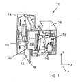
- a device 10 for dispensing coins comprises a circuit board 12 which is provided along an edge with a finishing part 14.
- the circuit board contains a number of electronic components 16 which are not shown in detail.
- the electronic components inter alia comprise components for driving the device 10.
- the control components comprise, for example, hardware and/or software.
- the hardware comprises for example a control unit, a memory, transistors, capacitors and/or resistors.
- the software comprises a suitable control program. The control program controls the operation of the device which is described below.
- the coin-outlet part 20 comprises a frame 22 provided with a slotted opening 24.
- the opening 24 is a coin-outlet opening and forms the end of a coin-dispensing duct which is not shown in the figure in any more detail.
- the coin-outlet opening 24 together with the entire device 10 can be connected to a coin-dispensing duct of a coin-dispensing unit, such as a hopper.
- the frame 22 furthermore comprises a casing 26 in which the parts illustrated in the following figures are housed.
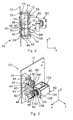
- the circuit board 12 contains, for example, two radiation sources 40, 42 and two radiation sensors 44, 46.
- two detectors comprising a combination of a radiation source and a radiation sensor are shown, but any number of one or more detectors is possible.
- the radiation sources and radiation sensors are attached to the circuit board by means of respective protuberances 48, 50, 52, 54, preferably by soldering.
- the radiation sources 48, 50 are arranged in such a manner that they can emit radiation via radiation paths 56, 58. To this end, the radiation sources 48, 50 project from the circuit board 12 into apertures 60, 62 in framework 64. From the sources, the radiation paths first pass the opening 24. On the other side of the opening 24, passages 66, 68 are provided in the framework 64.
- Deflecting elements are arranged in the passages 66, 68 to deflect the radiation in the desired direction, i.e. in the direction of the radiation sensors 52, 54.
- the deflecting elements comprise two prisms 70, 72 and 74, 76, respectively.
- the prisms are designed to deflect the respective radiation path in each case approximately 90 degrees.
- the radiation sources and the radiation sensors can be arranged on the same circuit board. This makes maintenance of the device 10 more efficient and less expensive, since only the circuit board 12 is replaced, for example in the case of failure.
- the radiation paths 56, 58 pass the opening 24 only once. For the remainder, their course to the radiation sensors 52, 54 runs internally inside the framework 64.
- the radiation sensors may be arranged opposite the respective radiation sources in the framework 64.
- the deflecting means may comprise other parts, such as an optical fibre and/or a mirror.
- closure element 80 Inside casing 26, a closure element 80 and operating means 82 which are coupled thereto are arranged. For the sake of clarity, the closure element 80 is hatched.
- the closure element 80 comprises a first closure element 84.
- the first closure element 84 is connected to one or more arms 86, which in turn are connected to the second closure element 88.
- the first closure element 84 and the second closure element 88 are approximately panel-shaped and formed as a single part. Together, the first and the second closure element form a U-shaped closure element 80.
- the closure element 80 is movable with respect to the passage 24 in order to close it off or leave it clear ( Figs. 3 and 4 , respectively).
- the closure element 80 comprises an operating part 90 which extends obliquely from the first closure element 84 having an approximately flat edge 92 at one end.
- a spring (not shown in the figures) is arranged between the arms 86 and the framework 64. The spring pushes the closure element 80 away from the framework 64 when the operating part is clear from plunger 104, i.e. when the plunger 104 has been pulled in ( Fig. 3 ).
- a second upright wall 94 is provided on the same side as the operating part.
- the second upright wall 94 is movably arranged inside U-shaped housing 96 which contains a location detector.
- the location detector comprises, for example, an optical sensor which is provided with a radiation source (not shown in any more detail) and an associated radiation detector for detecting the location of the upright wall 94.
- the housing 96 is connected to the frame 22 (see Fig. 1 ).
- the operating means 82 comprise a frame 100 which is connected to casing 26. Inside the frame 100, an actuator 102 is provided which, in a practical embodiment, comprises an electromagnet.
- the electromagnet comprises an electrical coil, in which a plunger 104 is movably arranged. At one end, the plunger 104 is provided with a circular flange 106. A spring 108 is arranged between the flange 106 and a casing of the electromagnet.
- the plunger 104 is pulled into the electromagnet.
- the cover 84 is pushed in the direction of the operating means 82 by the abovementioned spring which acts on the arm 86.
- the open position of use of the closure element 80 ( Fig. 3 ) is delimited by the edge of the flange 106 and/or by the plunger 104.
- the device 10 operates as follows. As mentioned above, the device has an open and a closed position of use. Figures 1 , 2 and 3 show the open position of use and Fig. 4 shows the closed position of use.
- the actuator 102 When the device 10 has to dispense coins, i.e. has to allow coins through the opening 24, the actuator 102 is activated. The actuator 102 pulls the plunger against the spring action of the spring 108, so that the closure element 80 is pushed from the opening 24 by a spring which is not shown. The closure element 80 then leaves the opening 24 clear in order to allow coins to pass.
- actuator 102 The operation of actuator 102 is stopped before the coins are dispensed or after the coins have been dispensed.
- the electrical power of an electromagnet will be stopped, following which the spring 108 pushes the plunger against the operating part 90.
- the plunger 104 pushes the cover 84 as far as into the opening 24, so that the latter is closed off.
- the edge of the flange 106 in this case locks the edge 92, and thus the closure element 80, against manual operation of the cover 84 from outside.
- Each of the radiation sources 48, 50 creates a radiation path which is interrupted for a period of time by a passing coin.
- the period of time is, for example, between 30 ms and 70 ms.
- Each interruption of the radiation path is registered by a control unit coupled to the radiation sensors 52, 54 as the passing of a single coin.
- the radiation is preferably emitted in a modulated manner. That is to say that the radiation is emitted in a pattern, with the result that fraud by means of a light source emitting light continuously is impossible.
- the device 10 comprises a second closure element.
- the second closure element can, for example, be operated simultaneously with the abovementioned closure element.
- the closure element is shaped as a U-shaped part, so that the cover 84 and the second closure element form a single entity.
- the second closure element prevents coins from entering the opening 24 during for example transportation or at other times when the device is switched off. This prevents possible malfunction after transportation.
- the cover 84 can close off the outlet side of the opening 24, while the second closure element can close off an inlet side, i.e. the side to which coins are supplied.
- the length is indicated by the direction x, the width by the direction y and the height by the direction z.
- the opening 24 has a height in the order of magnitude of 25 to 50 mm, preferably approximately 30 to 35 mm.
- the opening has a width in the order of magnitude of 3 to 10 mm, preferably approximately 5 to 6 mm.
- the underside 120 of the opening 24 is provided with or connected to a coin-dispensing duct having an angle of inclination with respect to a floor in the order of magnitude of 15 to 30 degrees, preferably approximately 15 to 20 degrees.
- the radiation sources 40, 42 comprise, for example, LEDs.
- the radiation emitted by the LEDs has, for example, a frequency which is in the range of infrared light.
- the closure element 80 comprises, for example, metal and/or a plastic reinforced with fibreglass.
- a fraudulent person would have to fit one receiver 122, 124 for each radiation source 40, 42 in order to determine the pattern and/or the frequency of the emitted radiation.
- a radiation source 126, 128 would have to be fitted for emitting radiation with the same pattern and the same frequency.
- the receivers 122, 124 and the radiation sources 126, 128 would have to be coupled by means of a control unit (not shown in any more detail). Fraud is prevented due to the fact that the width of the opening 24 is largely taken up by the receivers and the radiation sources, so that too little room is left to allow coins to pass.
- Radiation sources and receivers have a thickness in the order of magnitude 2 mm, while coins have a minimum thickness of approximately 1.5 mm. If a transmitter and a receiver have been fitted, the remaining width of the opening 24 is too small to allow a coin to pass.
- the opening 24 has a width d1 and a height d2.
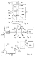
- Figs. 6 and 7 show an example of an application of the coin-detection station 10 in a coin-dispensing unit of a (gambling) machine.
- the coin-dispensing unit comprises a coin container 200, which is arranged in the interior of the unit and which holds a number of coins 202.
- the coins 202 have a thickness d3 and a diameter d4.
- the passage 24 has dimensions such that the thickness d3 of the coins fits inside the width d1 and that the diameter d4 fits inside the height d2.
- a duct 204 for dispensing coins extends from the coin container 200 in the direction of a coin-collecting tray 206.
- the duct 204 may have any suitable form and shape, depending on the unit in which the duct is located.
- the coin-collecting tray 206 is accessible via an opening 208 in the wall 210 of a housing of the (gambling) machine (not shown in any more detail). A user can remove coins from the collecting tray 206 via the opening.
- coins 202 roll on their side along the underside of the inclined duct 204 of the container 200 in the direction of the collecting tray 206.
- the direction is indicated by arrow 212.
- the duct 204 is provided with the coin-detection station 10 in a suitable location.
- the closure element 80 of the coin-detection station 10 can move in the direction of arrow 214 between the first position, shown in Fig. 7 , and the second position. In the first position, the closure element blocks the duct 204. In the second position, coins 202 are able to pass the coin-detection station.
- the coin-detection station 10 is coupled to a control unit (not shown in detail). When one or more coins are dispensed, the control unit emits a control signal to the operating means 82 in order to open the closure element 80.
- the control unit furthermore controls the radiation source(s) of the detection station and determines from a detection signal, originating from the radiation sensor(s), whether a coin has passed the detection station 10.
Landscapes
- Physics & Mathematics (AREA)
- General Physics & Mathematics (AREA)
- Control Of Vending Devices And Auxiliary Devices For Vending Devices (AREA)
- Testing Of Coins (AREA)
- Slot Machines And Peripheral Devices (AREA)
- Devices For Checking Fares Or Tickets At Control Points (AREA)
Applications Claiming Priority (2)
| Application Number | Priority Date | Filing Date | Title |
|---|---|---|---|
| NL1033426 | 2007-02-19 | ||
| NL1033631A NL1033631C2 (nl) | 2007-02-19 | 2007-04-02 | Inrichting en werkwijze voor het voorkomen van fraude bij het uitbetalen van munten. |
Publications (3)
| Publication Number | Publication Date |
|---|---|
| EP1959402A2 true EP1959402A2 (de) | 2008-08-20 |
| EP1959402A3 EP1959402A3 (de) | 2008-10-29 |
| EP1959402B1 EP1959402B1 (de) | 2010-05-05 |
Family
ID=38606853
Family Applications (1)
| Application Number | Title | Priority Date | Filing Date |
|---|---|---|---|
| EP08075123A Active EP1959402B1 (de) | 2007-02-19 | 2008-02-19 | Münzerkennungsstation mit Funktion zur Betrugsverhinderung |
Country Status (5)
| Country | Link |
|---|---|
| EP (1) | EP1959402B1 (de) |
| AT (1) | ATE467199T1 (de) |
| DE (1) | DE602008001113D1 (de) |
| ES (1) | ES2344328T3 (de) |
| NL (1) | NL1033631C2 (de) |
Citations (2)
| Publication number | Priority date | Publication date | Assignee | Title |
|---|---|---|---|---|
| US5767506A (en) | 1994-10-03 | 1998-06-16 | Coin Controls Ltd. | Optical coin sensing station having a passageway and beam splitters |
| WO2003049049A1 (en) | 2001-12-06 | 2003-06-12 | Suzo International (Nl) B.V. | A device for dispensing disc-shaped objects, such as coins |
Family Cites Families (5)
| Publication number | Priority date | Publication date | Assignee | Title |
|---|---|---|---|---|
| DE2334664A1 (de) * | 1973-07-07 | 1975-01-30 | Alfred Krauth Apparatebau Kg P | Muenz - ausstossvorrichtung |
| DE9310313U1 (de) * | 1993-07-10 | 1993-11-11 | Tas, Sabahattin, 45879 Gelsenkirchen | Schutzvorrichtung vor Manipulationen für einen Spielautomaten |
| US5516293A (en) * | 1994-04-07 | 1996-05-14 | Bally Gaming International, Inc. | Gaming machine coin hopper coin sensor |
| WO1998012672A1 (en) * | 1996-09-23 | 1998-03-26 | Quadrum Telecommunications, Inc. | Coin return anti-stuffing apparatus and method |
| US6749052B2 (en) * | 2000-10-19 | 2004-06-15 | Igames Entertainment, Inc. | Anti-cheating device for a gaming machine |
-
2007
- 2007-04-02 NL NL1033631A patent/NL1033631C2/nl active Search and Examination
-
2008
- 2008-02-19 ES ES08075123T patent/ES2344328T3/es active Active
- 2008-02-19 AT AT08075123T patent/ATE467199T1/de not_active IP Right Cessation
- 2008-02-19 DE DE602008001113T patent/DE602008001113D1/de active Active
- 2008-02-19 EP EP08075123A patent/EP1959402B1/de active Active
Patent Citations (2)
| Publication number | Priority date | Publication date | Assignee | Title |
|---|---|---|---|---|
| US5767506A (en) | 1994-10-03 | 1998-06-16 | Coin Controls Ltd. | Optical coin sensing station having a passageway and beam splitters |
| WO2003049049A1 (en) | 2001-12-06 | 2003-06-12 | Suzo International (Nl) B.V. | A device for dispensing disc-shaped objects, such as coins |
Also Published As
| Publication number | Publication date |
|---|---|
| EP1959402A3 (de) | 2008-10-29 |
| DE602008001113D1 (de) | 2010-06-17 |
| EP1959402B1 (de) | 2010-05-05 |
| ATE467199T1 (de) | 2010-05-15 |
| NL1033631C2 (nl) | 2008-08-20 |
| ES2344328T3 (es) | 2010-08-24 |
Similar Documents
| Publication | Publication Date | Title |
|---|---|---|
| US6736250B2 (en) | Method and apparatus for fraud detection | |
| US5429222A (en) | Device for verifying the conformity of and for routing objects inserted in a dispenser | |
| CA1169380A (en) | Method and installation for encouraging the restitution of shopping carts in a supermarket | |
| EP0560832B1 (de) | Münzprüfer | |
| US20100066490A1 (en) | Apparatus and Method for Rejecting Jammed Coins | |
| EP1959402B1 (de) | Münzerkennungsstation mit Funktion zur Betrugsverhinderung | |
| WO2009138187A1 (de) | Geldausgabeautomat | |
| US20160217655A1 (en) | Token Dispenser System, Installation Apparatus, and Method | |
| US6749052B2 (en) | Anti-cheating device for a gaming machine | |
| JP2006527876A (ja) | コイン払出装置 | |
| CN104240410A (zh) | 结算系统和用于运行结算系统的方法 | |
| RU2671188C1 (ru) | Устройство для обработки монет и соответствующий способ классификации монет | |
| EP1191488B1 (de) | Münzausgabemechanismus | |
| JP5303700B2 (ja) | 弾球遊技機 | |
| CA2479788A1 (en) | A coin validator with movable beam deflector | |
| PH12015502461B1 (en) | Amusement machine and monitoring system | |
| AU2011101285A4 (en) | Coin or token processing apparatus | |
| RU2093891C1 (ru) | Впускное устройство монетного автомата | |
| JP2006252398A (ja) | コイン機器およびそれに用いるセンサ | |
| JP2006026082A (ja) | 遊技機 | |
| JP2955775B2 (ja) | 硬貨処理装置 | |
| JP6516636B2 (ja) | 遊技機 | |
| JP3030564B2 (ja) | 硬貨処理装置 | |
| JP2009112559A (ja) | メダル通過検知センサ及び遊技機の投入メダル選別装置 | |
| JP2007000502A (ja) | 遊技機 |
Legal Events
| Date | Code | Title | Description |
|---|---|---|---|
| PUAI | Public reference made under article 153(3) epc to a published international application that has entered the european phase |
Free format text: ORIGINAL CODE: 0009012 |
|
| AK | Designated contracting states |
Kind code of ref document: A2 Designated state(s): AT BE BG CH CY CZ DE DK EE ES FI FR GB GR HR HU IE IS IT LI LT LU LV MC MT NL NO PL PT RO SE SI SK TR |
|
| AX | Request for extension of the european patent |
Extension state: AL BA MK RS |
|
| PUAL | Search report despatched |
Free format text: ORIGINAL CODE: 0009013 |
|
| AK | Designated contracting states |
Kind code of ref document: A3 Designated state(s): AT BE BG CH CY CZ DE DK EE ES FI FR GB GR HR HU IE IS IT LI LT LU LV MC MT NL NO PL PT RO SE SI SK TR |
|
| AX | Request for extension of the european patent |
Extension state: AL BA MK RS |
|
| 17P | Request for examination filed |
Effective date: 20090409 |
|
| AKX | Designation fees paid |
Designated state(s): AT BE BG CH CY CZ DE DK EE ES FI FR GB GR HR HU IE IS IT LI LT LU LV MC MT NL NO PL PT RO SE SI SK TR |
|
| GRAP | Despatch of communication of intention to grant a patent |
Free format text: ORIGINAL CODE: EPIDOSNIGR1 |
|
| GRAS | Grant fee paid |
Free format text: ORIGINAL CODE: EPIDOSNIGR3 |
|
| GRAA | (expected) grant |
Free format text: ORIGINAL CODE: 0009210 |
|
| AK | Designated contracting states |
Kind code of ref document: B1 Designated state(s): AT BE BG CH CY CZ DE DK EE ES FI FR GB GR HR HU IE IS IT LI LT LU LV MC MT NL NO PL PT RO SE SI SK TR |
|
| REG | Reference to a national code |
Ref country code: GB Ref legal event code: FG4D |
|
| REG | Reference to a national code |
Ref country code: CH Ref legal event code: EP |
|
| REG | Reference to a national code |
Ref country code: IE Ref legal event code: FG4D |
|
| REG | Reference to a national code |
Ref country code: NL Ref legal event code: T3 |
|
| REF | Corresponds to: |
Ref document number: 602008001113 Country of ref document: DE Date of ref document: 20100617 Kind code of ref document: P |
|
| REG | Reference to a national code |
Ref country code: ES Ref legal event code: FG2A Ref document number: 2344328 Country of ref document: ES Kind code of ref document: T3 |
|
| LTIE | Lt: invalidation of european patent or patent extension |
Effective date: 20100505 |
|
| PG25 | Lapsed in a contracting state [announced via postgrant information from national office to epo] |
Ref country code: SE Free format text: LAPSE BECAUSE OF FAILURE TO SUBMIT A TRANSLATION OF THE DESCRIPTION OR TO PAY THE FEE WITHIN THE PRESCRIBED TIME-LIMIT Effective date: 20100505 Ref country code: LT Free format text: LAPSE BECAUSE OF FAILURE TO SUBMIT A TRANSLATION OF THE DESCRIPTION OR TO PAY THE FEE WITHIN THE PRESCRIBED TIME-LIMIT Effective date: 20100505 Ref country code: NO Free format text: LAPSE BECAUSE OF FAILURE TO SUBMIT A TRANSLATION OF THE DESCRIPTION OR TO PAY THE FEE WITHIN THE PRESCRIBED TIME-LIMIT Effective date: 20100805 |
|
| PG25 | Lapsed in a contracting state [announced via postgrant information from national office to epo] |
Ref country code: SI Free format text: LAPSE BECAUSE OF FAILURE TO SUBMIT A TRANSLATION OF THE DESCRIPTION OR TO PAY THE FEE WITHIN THE PRESCRIBED TIME-LIMIT Effective date: 20100505 Ref country code: FI Free format text: LAPSE BECAUSE OF FAILURE TO SUBMIT A TRANSLATION OF THE DESCRIPTION OR TO PAY THE FEE WITHIN THE PRESCRIBED TIME-LIMIT Effective date: 20100505 Ref country code: AT Free format text: LAPSE BECAUSE OF FAILURE TO SUBMIT A TRANSLATION OF THE DESCRIPTION OR TO PAY THE FEE WITHIN THE PRESCRIBED TIME-LIMIT Effective date: 20100505 Ref country code: HR Free format text: LAPSE BECAUSE OF FAILURE TO SUBMIT A TRANSLATION OF THE DESCRIPTION OR TO PAY THE FEE WITHIN THE PRESCRIBED TIME-LIMIT Effective date: 20100505 Ref country code: LV Free format text: LAPSE BECAUSE OF FAILURE TO SUBMIT A TRANSLATION OF THE DESCRIPTION OR TO PAY THE FEE WITHIN THE PRESCRIBED TIME-LIMIT Effective date: 20100505 Ref country code: IS Free format text: LAPSE BECAUSE OF FAILURE TO SUBMIT A TRANSLATION OF THE DESCRIPTION OR TO PAY THE FEE WITHIN THE PRESCRIBED TIME-LIMIT Effective date: 20100905 |
|
| PG25 | Lapsed in a contracting state [announced via postgrant information from national office to epo] |
Ref country code: PL Free format text: LAPSE BECAUSE OF FAILURE TO SUBMIT A TRANSLATION OF THE DESCRIPTION OR TO PAY THE FEE WITHIN THE PRESCRIBED TIME-LIMIT Effective date: 20100505 Ref country code: CY Free format text: LAPSE BECAUSE OF FAILURE TO SUBMIT A TRANSLATION OF THE DESCRIPTION OR TO PAY THE FEE WITHIN THE PRESCRIBED TIME-LIMIT Effective date: 20100602 |
|
| PG25 | Lapsed in a contracting state [announced via postgrant information from national office to epo] |
Ref country code: EE Free format text: LAPSE BECAUSE OF FAILURE TO SUBMIT A TRANSLATION OF THE DESCRIPTION OR TO PAY THE FEE WITHIN THE PRESCRIBED TIME-LIMIT Effective date: 20100505 Ref country code: DK Free format text: LAPSE BECAUSE OF FAILURE TO SUBMIT A TRANSLATION OF THE DESCRIPTION OR TO PAY THE FEE WITHIN THE PRESCRIBED TIME-LIMIT Effective date: 20100505 |
|
| PG25 | Lapsed in a contracting state [announced via postgrant information from national office to epo] |
Ref country code: SK Free format text: LAPSE BECAUSE OF FAILURE TO SUBMIT A TRANSLATION OF THE DESCRIPTION OR TO PAY THE FEE WITHIN THE PRESCRIBED TIME-LIMIT Effective date: 20100505 Ref country code: BE Free format text: LAPSE BECAUSE OF FAILURE TO SUBMIT A TRANSLATION OF THE DESCRIPTION OR TO PAY THE FEE WITHIN THE PRESCRIBED TIME-LIMIT Effective date: 20100505 Ref country code: CZ Free format text: LAPSE BECAUSE OF FAILURE TO SUBMIT A TRANSLATION OF THE DESCRIPTION OR TO PAY THE FEE WITHIN THE PRESCRIBED TIME-LIMIT Effective date: 20100505 Ref country code: RO Free format text: LAPSE BECAUSE OF FAILURE TO SUBMIT A TRANSLATION OF THE DESCRIPTION OR TO PAY THE FEE WITHIN THE PRESCRIBED TIME-LIMIT Effective date: 20100505 |
|
| PLBE | No opposition filed within time limit |
Free format text: ORIGINAL CODE: 0009261 |
|
| STAA | Information on the status of an ep patent application or granted ep patent |
Free format text: STATUS: NO OPPOSITION FILED WITHIN TIME LIMIT |
|
| 26N | No opposition filed |
Effective date: 20110208 |
|
| REG | Reference to a national code |
Ref country code: DE Ref legal event code: R097 Ref document number: 602008001113 Country of ref document: DE Effective date: 20110207 |
|
| PG25 | Lapsed in a contracting state [announced via postgrant information from national office to epo] |
Ref country code: GR Free format text: LAPSE BECAUSE OF FAILURE TO SUBMIT A TRANSLATION OF THE DESCRIPTION OR TO PAY THE FEE WITHIN THE PRESCRIBED TIME-LIMIT Effective date: 20100806 |
|
| PG25 | Lapsed in a contracting state [announced via postgrant information from national office to epo] |
Ref country code: MC Free format text: LAPSE BECAUSE OF NON-PAYMENT OF DUE FEES Effective date: 20110228 |
|
| REG | Reference to a national code |
Ref country code: IE Ref legal event code: MM4A |
|
| PG25 | Lapsed in a contracting state [announced via postgrant information from national office to epo] |
Ref country code: MT Free format text: LAPSE BECAUSE OF FAILURE TO SUBMIT A TRANSLATION OF THE DESCRIPTION OR TO PAY THE FEE WITHIN THE PRESCRIBED TIME-LIMIT Effective date: 20100505 |
|
| REG | Reference to a national code |
Ref country code: DE Ref legal event code: R119 Ref document number: 602008001113 Country of ref document: DE Effective date: 20110901 |
|
| PG25 | Lapsed in a contracting state [announced via postgrant information from national office to epo] |
Ref country code: IE Free format text: LAPSE BECAUSE OF NON-PAYMENT OF DUE FEES Effective date: 20110219 |
|
| REG | Reference to a national code |
Ref country code: NL Ref legal event code: PLED Effective date: 20120822 |
|
| REG | Reference to a national code |
Ref country code: CH Ref legal event code: PL |
|
| PG25 | Lapsed in a contracting state [announced via postgrant information from national office to epo] |
Ref country code: LI Free format text: LAPSE BECAUSE OF NON-PAYMENT OF DUE FEES Effective date: 20120229 Ref country code: CH Free format text: LAPSE BECAUSE OF NON-PAYMENT OF DUE FEES Effective date: 20120229 |
|
| PG25 | Lapsed in a contracting state [announced via postgrant information from national office to epo] |
Ref country code: LU Free format text: LAPSE BECAUSE OF NON-PAYMENT OF DUE FEES Effective date: 20110219 |
|
| PG25 | Lapsed in a contracting state [announced via postgrant information from national office to epo] |
Ref country code: DE Free format text: LAPSE BECAUSE OF NON-PAYMENT OF DUE FEES Effective date: 20110901 |
|
| PG25 | Lapsed in a contracting state [announced via postgrant information from national office to epo] |
Ref country code: PT Free format text: LAPSE BECAUSE OF NON-PAYMENT OF DUE FEES Effective date: 20100505 |
|
| PG25 | Lapsed in a contracting state [announced via postgrant information from national office to epo] |
Ref country code: TR Free format text: LAPSE BECAUSE OF FAILURE TO SUBMIT A TRANSLATION OF THE DESCRIPTION OR TO PAY THE FEE WITHIN THE PRESCRIBED TIME-LIMIT Effective date: 20100505 Ref country code: BG Free format text: LAPSE BECAUSE OF FAILURE TO SUBMIT A TRANSLATION OF THE DESCRIPTION OR TO PAY THE FEE WITHIN THE PRESCRIBED TIME-LIMIT Effective date: 20100805 |
|
| PG25 | Lapsed in a contracting state [announced via postgrant information from national office to epo] |
Ref country code: HU Free format text: LAPSE BECAUSE OF FAILURE TO SUBMIT A TRANSLATION OF THE DESCRIPTION OR TO PAY THE FEE WITHIN THE PRESCRIBED TIME-LIMIT Effective date: 20100505 |
|
| REG | Reference to a national code |
Ref country code: FR Ref legal event code: PLFP Year of fee payment: 9 |
|
| REG | Reference to a national code |
Ref country code: FR Ref legal event code: PLFP Year of fee payment: 10 |
|
| PGFP | Annual fee paid to national office [announced via postgrant information from national office to epo] |
Ref country code: FR Payment date: 20170227 Year of fee payment: 10 |
|
| PGFP | Annual fee paid to national office [announced via postgrant information from national office to epo] |
Ref country code: CH Payment date: 20170317 Year of fee payment: 4 |
|
| PGFP | Annual fee paid to national office [announced via postgrant information from national office to epo] |
Ref country code: IT Payment date: 20170223 Year of fee payment: 10 |
|
| REG | Reference to a national code |
Ref country code: NL Ref legal event code: MM Effective date: 20180301 |
|
| GBPC | Gb: european patent ceased through non-payment of renewal fee |
Effective date: 20180219 |
|
| REG | Reference to a national code |
Ref country code: FR Ref legal event code: ST Effective date: 20181031 |
|
| PG25 | Lapsed in a contracting state [announced via postgrant information from national office to epo] |
Ref country code: NL Free format text: LAPSE BECAUSE OF NON-PAYMENT OF DUE FEES Effective date: 20180301 |
|
| REG | Reference to a national code |
Ref country code: NL Ref legal event code: NE Effective date: 20190215 |
|
| PG25 | Lapsed in a contracting state [announced via postgrant information from national office to epo] |
Ref country code: FR Free format text: LAPSE BECAUSE OF NON-PAYMENT OF DUE FEES Effective date: 20180228 Ref country code: IT Free format text: LAPSE BECAUSE OF NON-PAYMENT OF DUE FEES Effective date: 20180219 Ref country code: GB Free format text: LAPSE BECAUSE OF NON-PAYMENT OF DUE FEES Effective date: 20180219 |
|
| REG | Reference to a national code |
Ref country code: GB Ref legal event code: S28 Free format text: APPLICATION FILED |
|
| REG | Reference to a national code |
Ref country code: GB Ref legal event code: S28 Free format text: RESTORATION ALLOWED Effective date: 20190520 |
|
| PGFP | Annual fee paid to national office [announced via postgrant information from national office to epo] |
Ref country code: ES Payment date: 20250311 Year of fee payment: 18 |
|
| PGFP | Annual fee paid to national office [announced via postgrant information from national office to epo] |
Ref country code: GB Payment date: 20250109 Year of fee payment: 18 |