EP1959230A2 - Method and apparatus for controlling the contact type probe of a profile measuring machine - Google Patents
Method and apparatus for controlling the contact type probe of a profile measuring machine Download PDFInfo
- Publication number
- EP1959230A2 EP1959230A2 EP08001246A EP08001246A EP1959230A2 EP 1959230 A2 EP1959230 A2 EP 1959230A2 EP 08001246 A EP08001246 A EP 08001246A EP 08001246 A EP08001246 A EP 08001246A EP 1959230 A2 EP1959230 A2 EP 1959230A2
- Authority
- EP
- European Patent Office
- Prior art keywords
- contact
- force
- contact point
- profiling
- determination level
- Prior art date
- Legal status (The legal status is an assumption and is not a legal conclusion. Google has not performed a legal analysis and makes no representation as to the accuracy of the status listed.)
- Granted
Links
- 239000000523 sample Substances 0.000 title claims abstract description 41
- 238000000034 method Methods 0.000 title claims description 14
- 238000005259 measurement Methods 0.000 claims abstract description 62
- 241001422033 Thestylus Species 0.000 description 2
- 230000001133 acceleration Effects 0.000 description 2
- 238000010586 diagram Methods 0.000 description 2
- 230000005284 excitation Effects 0.000 description 2
- 229910052782 aluminium Inorganic materials 0.000 description 1
- XAGFODPZIPBFFR-UHFFFAOYSA-N aluminium Chemical compound [Al] XAGFODPZIPBFFR-UHFFFAOYSA-N 0.000 description 1
- 230000007423 decrease Effects 0.000 description 1
- 238000001514 detection method Methods 0.000 description 1
- 229910003460 diamond Inorganic materials 0.000 description 1
- 239000010432 diamond Substances 0.000 description 1
- 229910052751 metal Inorganic materials 0.000 description 1
- 239000002184 metal Substances 0.000 description 1
- 239000010979 ruby Substances 0.000 description 1
- 229910001750 ruby Inorganic materials 0.000 description 1
- 230000000087 stabilizing effect Effects 0.000 description 1
- 230000003746 surface roughness Effects 0.000 description 1
Images





Classifications
-
- G—PHYSICS
- G01—MEASURING; TESTING
- G01B—MEASURING LENGTH, THICKNESS OR SIMILAR LINEAR DIMENSIONS; MEASURING ANGLES; MEASURING AREAS; MEASURING IRREGULARITIES OF SURFACES OR CONTOURS
- G01B3/00—Measuring instruments characterised by the use of mechanical techniques
- G01B3/002—Details
- G01B3/008—Arrangements for controlling the measuring force
-
- G—PHYSICS
- G01—MEASURING; TESTING
- G01B—MEASURING LENGTH, THICKNESS OR SIMILAR LINEAR DIMENSIONS; MEASURING ANGLES; MEASURING AREAS; MEASURING IRREGULARITIES OF SURFACES OR CONTOURS
- G01B5/00—Measuring arrangements characterised by the use of mechanical techniques
- G01B5/004—Measuring arrangements characterised by the use of mechanical techniques for measuring coordinates of points
- G01B5/008—Measuring arrangements characterised by the use of mechanical techniques for measuring coordinates of points using coordinate measuring machines
- G01B5/012—Contact-making feeler heads therefor
-
- G—PHYSICS
- G01—MEASURING; TESTING
- G01B—MEASURING LENGTH, THICKNESS OR SIMILAR LINEAR DIMENSIONS; MEASURING ANGLES; MEASURING AREAS; MEASURING IRREGULARITIES OF SURFACES OR CONTOURS
- G01B7/00—Measuring arrangements characterised by the use of electric or magnetic techniques
- G01B7/004—Measuring arrangements characterised by the use of electric or magnetic techniques for measuring coordinates of points
- G01B7/008—Measuring arrangements characterised by the use of electric or magnetic techniques for measuring coordinates of points using coordinate measuring machines
- G01B7/012—Contact-making feeler heads therefor
Definitions
- the present invention relates to a profiling controlling method and controller for contact type probes, and a contact type measuring machine. More particularly, it relates to a contact type probe profiling controlling method and controller capable of measuring a shape, roughness of a surface or the like of a soft object to be measured such as a plastic lens or aluminum product while leaving noncontact trace on the object, and a contact type measuring machine equipped with the contact type probe which is profiling-controlled by the controller.
- FIG. 2 An example of a relationship between input amplitude and output amplitude of the force sensor 10 is shown in Fig. 2 .
- the stylus 14 vertically ultrasonically vibrates at an amplitude of, for example, several nm to several tens nm, and a signal of an output amplitude Po appears in the detecting piezoelectric element 24.
- the target measurement force (force judged at which contact is stabilized) is compared, for detecting the contact, with the measurement force detected by the force sensor 10, and the position control is switched to the force control at the time when the measurement force exceeds the target measurement force.
- a delay time e.g. about 100 ⁇ s, is caused to contact determination due to delay of an electric circuit, delay of calculation time of a digital controller, or the like. Consequently, as shown in Fig. 6 , the probe is pushed into the work more deeply (over-push) than a position (measurement position) where the sensor is pushed into the work by the target measurement force.
- the approach speed must be reduced as much as possible, and the measurement efficiency is conspicuously lowered.
- the present invention was made in order to solve the above problem, and aims at preventing a contact trace from occurring on an object to be measured without reducing an approach speed as much as possible and lowering measurement efficiency.
- a contact determination level is provided for detecting a predetermined force lower than the target measurement force is applied to the contact point, contact determination is performed at the time when the force applied to the contact point reaches the contact determination level during the approach, and the contact point is shifted from position control to force control for bringing the contact point into contact with the object to be measured by the target measurement force.
- the predetermined force can be considered to be a force at which contact can be predicted for the obj ect to be measured and the contact point begins.
- a command value of the force control is interpolated and gradually increased from the contact determination level to the target measurement force, and thus an impact increase or over-shoot can be prevented from causing due to high response.
- an interpolation time of the force control command value can be made variable.
- the present invention provides a profiling controller for contact type probes, in which the contact point is moved along the surface of the object to be measured, while being in contact with the object by a fixed measurement force, the controller including:
- the present invention provides a contact type measuring machine equipped with the contact type probe profiling-controlled by the controller.
- a contact determination level is provided for approach to an object to be measured, the level for detecting a predetermined force (force that it can be predicted contact begins) lower than the target measurement force (force that it is judged contact is stable for measurement) is applied to a contact point, the force being, contact determination is performed at the time when force applied to the contact point reaches the contact determination level during the approach, and the contact point is quickly shifted from position control to force control for bringing, by the target measurement force, the contact point into contact with the object to be measured.
- a predetermined force force that it can be predicted contact begins
- the target measurement force force that it is judged contact is stable for measurement
- the contact determination level is set as a state where measurement force smaller than the target measurement force is generated.
- the push-in amount of a position of the probe at the contact determination level is smaller than that of a position of the probe pushed into the object by the target measurement force.
- the contact determination is performed at the time when the force exceeds the contact determination level, and the position control is switched to the force control. Therefore, if an approach speed is selected so as to satisfy the following inequality:
- Fig. 9 shows a constitutional example of a contact type profiling probe system employing a digital controller, to carry out the embodiment.
- a probe 30 includes: a force sensor 10 for detecting the measurement force, the sensor being similar to a conventional sensor; a drive actuator 32 for driving a tip of the probe in positioning control and force fixed profiling control; and a scale 34 and scale detector 36 for performing position feedback and counting a shape position detection value.
- a controller 40 includes: a drive amplifier 42 for supplying power to the drive actuator 32 of the probe 30 side; a counter 44 for counting a position of the probe based on output of the scale detector 36; an analog/digital (A/D) converter 46 for converting an analog signal from the force sensor 10 into a digital signal; and a digital control calculating part 48 capable of controlling the switching of the position control and force control.
- A/D analog/digital
- the probe in terms of improvement of measurement efficiency, the probe is desired to follow shape variation, as fast as possible, of the object to be measured. Accordingly, it is required to set a loop gain of a force control loop high and to make high-response. In this state, when the first embodiment is applied, as shown in Fig. 10 , impact increase and over-shoot occur due to the high response, and there is a possibility that the contact trace remains on the object to be measured.
- a force control command when the position control is switched to the force control is not raised at once to the target measurement force, but interpolated and gradually raised so as to approach the target measurement force.
- the impact and the over-shoot in contact are reduced, and the contact trace can be prevented from occurring.
- Fig. 12 shows a constitutional example of a probe system of the embodiment.
- the probe system is different from the probe system shown in Fig. 9 in the point that a force control command interpolation processing part for subjecting the target measurement force to interpolation processing and making it into the force control command is provided in the digital control calculating part 48.
- the system is similar to that shown in Fig. 9 in other points, therefore, description of the points is omitted.
- force control command interpolation processing may include the following performances.
Landscapes
- Physics & Mathematics (AREA)
- General Physics & Mathematics (AREA)
- A Measuring Device Byusing Mechanical Method (AREA)
- Length Measuring Devices With Unspecified Measuring Means (AREA)
Abstract
Description
- The present invention relates to a profiling controlling method and controller for contact type probes, and a contact type measuring machine. More particularly, it relates to a contact type probe profiling controlling method and controller capable of measuring a shape, roughness of a surface or the like of a soft object to be measured such as a plastic lens or aluminum product while leaving noncontact trace on the object, and a contact type measuring machine equipped with the contact type probe which is profiling-controlled by the controller.
- As a touch sensor for probes used in the case of measuring a fine surface shape of an object to be measured with a fine shape measuring machine or a surface roughness measuring machine, or measuring an inner shape of a hole with a small hole measuring machine, the applicant proposes an excitation type force sensor shown in
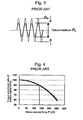
Fig. 1 , the sensor being disclosed in Japanese Published Unexamined Patent ApplicationNo.2001-91206 force sensor 10,piezoelectric elements 20 is adhered to both surfaces ofametallic base 12 integrated with astylus 14, the piezoelectric element being separated into an exciting electrode (referred to as an exciting piezoelectric element) 22 and a detecting electrode (referred to as a detecting piezoelectric element) 24. Additionally, acontact point 16 constituted by a diamond chip or ruby ball is fixed to a tip (lower end inFig. 1 ) of thestylus 14. - An example of a relationship between input amplitude and output amplitude of the
force sensor 10 is shown inFig. 2 . In the case where thecontact point 16 is in noncontact with awork 8 which is an object to be measured, when a specified input amplitude Pi is applied to the excitingpiezoelectric element 22, thestylus 14 vertically ultrasonically vibrates at an amplitude of, for example, several nm to several tens nm, and a signal of an output amplitude Po appears in the detectingpiezoelectric element 24. - When the
contact point 16 comes into contact with thework 8, as shown inFig. 3 , the magnitude of the output amplitude decreases from Po to Px. When an output amplitude ratio k0 = (Px/Po)X 100 = 90%, 135 [µN] is obtained as measurement force F in an example of a relationship between the output amplitude ratio k0 and the measurement force F. When theforce sensor 10 connected to an actuator (not shown) is controlled so that the output amplitude ratio k0 is constantly kept, measurement force (F) fixed profiling measurement (referred to as force fixed profiling measurement) can be realized that is capable of measuring a shape or roughness of thework 8. - In the case of measuring the work with use of a contact type probe, as shown in
Fig. 5 , approach (operation of shifting the probe, at low speed, for contact with the object to be measured, detecting the contact, and stabilizing the contact by a target measurement force) to thework 8, which is the object to be measured, is required. Since, in such aforce sensor 10, there occurs no measurement force unless the sensor comes into contact with the object to be measured, approach drive before contact with the force sensor and the object to be measured is normally performed by position control, etc., using a scale detector, and the position control is switched to force control after the contact with the sensor and thework 8. Then, thework 8 or probe (force sensor 10) attachment side is driven, and the sensor scans a surface of the work in a force control state. During the scan, a scale value of the probe and a position of the work are read as a shape measurement position. Then, after the force fixed profiling measurement ends, the force control is switched to the position control, and the sensor retracts to a retraction position. - During the approach operation, the target measurement force (force judged at which contact is stabilized) is compared, for detecting the contact, with the measurement force detected by the
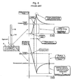
force sensor 10, and the position control is switched to the force control at the time when the measurement force exceeds the target measurement force. In this case, a delay time, e.g. about 100 µs, is caused to contact determination due to delay of an electric circuit, delay of calculation time of a digital controller, or the like.
Consequently, as shown inFig. 6 , the probe is pushed into the work more deeply (over-push) than a position (measurement position) where the sensor is pushed into the work by the target measurement force. Further, when an approach speed is increased for raising measurement efficiency, not only does the amount of over-push become large but an impact in the contact become large, and, a contact trace remains on the object to be measured, which may cause problem especially in the case where the object is a lens or metal mold. - In order to prevent a contact trace from occurring due to approach, as shown in
Fig. 7 , a method has been conventionally employed that reduces, by reducing the approach speed as much as possible, the push-in amount, as much as possible, caused by the delay time in the contact determination and simultaneously reduces the impact in the contact, and thus prevents the contact trace from occurring on the object to be measured. - However, in the method, the approach speed must be reduced as much as possible, and the measurement efficiency is conspicuously lowered.
- The present invention was made in order to solve the above problem, and aims at preventing a contact trace from occurring on an object to be measured without reducing an approach speed as much as possible and lowering measurement efficiency.
- In order to solve the above problem, in the present invention, in profiling control of a contact type probe in which a contact point is moved along the object to be measured, while being in contact with the obj ect by a fixed measurement force, a contact determination level is provided for detecting a predetermined force lower than the target measurement force is applied to the contact point, contact determination is performed at the time when the force applied to the contact point reaches the contact determination level during the approach, and the contact point is shifted from position control to force control for bringing the contact point into contact with the object to be measured by the target measurement force.
- The predetermined force can be considered to be a force at which contact can be predicted for the obj ect to be measured and the contact point begins.
- The approach speed can be selected so as to satisfy the following inequality:
- (push-in amount at contact determination level
- + push-in amount by delay time of contact determination)
- ≤ push-in amount by measurement force.
- A command value of the force control is interpolated and gradually increased from the contact determination level to the target measurement force, and thus an impact increase or over-shoot can be prevented from causing due to high response.
- Additionally, an interpolation curve of the force control command value can be classified into a linear type, exponent type or S-curve type.
- Additionally, an interpolation time of the force control command value can be made variable.
- The present invention provides a profiling controller for contact type probes, in which the contact point is moved along the surface of the object to be measured, while being in contact with the object by a fixed measurement force, the controller including:
- contact detecting means for detecting a predetermined contact determination level force lower than the target measurement force is applied to the contact point;
- position controlling means for controlling a position of the contact point;
- force controlling means for controlling measurement force applied to the contact point; and
- means for performing the contact determination at the time when the force applied to the contact point reaches the contact determination level during the approach, and shifting the contact point from the position control to the force control for bringing, by the target measurement force, the contact point into contact with the object to be measured.
- Additionally, the present invention provides a contact type measuring machine equipped with the contact type probe profiling-controlled by the controller.
- According to the present invention, the contact trace can be prevented from occurring on the object to be measured without reducing the approach speed as much as possible and lowering measurement efficiency.
- These and other novel features and advantages of the present invention will become apparent from the following detailed description of preferred embodiments.
- The preferred embodiments will be described with reference to the drawings, wherein like elements have been denoted throughout the figures with like reference numerals, and wherein;
-
Fig. 1 is a perspective view of a force sensor disclosed inpatent document 1. -
Fig. 2 is a graph indicating an example of a relationship between excitation amplitude and output amplitude, disclosed inpatent document 1. -
Fig. 3 is a graph indicating an example of change in the output amplitude at contact, disclosed inpatent document 1. -
Fig. 4 is a graph indicating an example of a relationship between an output amplitude ratio and measurement force, disclosed inpatent document 1. -
Fig. 5 is a view showing an example of force fixed profile measurement using the force sensor. -
Fig. 6 is a view showing a state where a contact trace occurs, due to approach, on an obj ect to be measured, disclosed inpatent document 1. -
Fig. 7 is a graph indicating a state where an approach speed is low, disclosed inpatent document 1. -
Fig. 8 is a graph indicating operation of a first embodiment of the present invention. -
Fig. 9 is a block diagram illustrating a constitutional example of a probe system for carrying out the first embodiment. -
Fig. 10 is a graph indicating a problem of the first embodiment. -
Fig. 11 is a graph indicating operation of a second embodiment of the present invention solving the problem of the first embodiment. -
Fig. 12 is a block diagram illustrating a constitutional example of a probe system for carrying out the second embodiment. -
Fig. 13 is a graph indicating an example of an interpolation curve of a force control command of the second embodiment. - Embodiments of the present invention will be described below in detail with reference to the drawings.
- In a first embodiment of the present invention, as shown in
Fig. 8 , a contact determination level is provided for approach to an object to be measured, the level for detecting a predetermined force (force that it can be predicted contact begins) lower than the target measurement force (force that it is judged contact is stable for measurement) is applied to a contact point, the force being, contact determination is performed at the time when force applied to the contact point reaches the contact determination level during the approach, and the contact point is quickly shifted from position control to force control for bringing, by the target measurement force, the contact point into contact with the object to be measured. - Here, the contact determination level is set as a state where measurement force smaller than the target measurement force is generated. The push-in amount of a position of the probe at the contact determination level is smaller than that of a position of the probe pushed into the object by the target measurement force. When the force applied to the contact point reaches the contact determination level, the contact determination is performed, and position control is switched to force control.
- In the method, the contact determination is performed at the time when the force exceeds the contact determination level, and the position control is switched to the force control. Therefore, if an approach speed is selected so as to satisfy the following inequality:
- (push-in amount at contact determination level
- + push-in amount by delay time of contact determination)
- ≤ push-in amount by measurement force,
-
Fig. 9 shows a constitutional example of a contact type profiling probe system employing a digital controller, to carry out the embodiment. InFig. 9 , aprobe 30 includes: aforce sensor 10 for detecting the measurement force, the sensor being similar to a conventional sensor; adrive actuator 32 for driving a tip of the probe in positioning control and force fixed profiling control; and ascale 34 andscale detector 36 for performing position feedback and counting a shape position detection value. - Additionally, a controller 40 includes: a
drive amplifier 42 for supplying power to thedrive actuator 32 of theprobe 30 side; a counter 44 for counting a position of the probe based on output of thescale detector 36; an analog/digital (A/D)converter 46 for converting an analog signal from theforce sensor 10 into a digital signal; and a digitalcontrol calculating part 48 capable of controlling the switching of the position control and force control. - Moreover, in the case of the probe system for performing the force fixed profiling as shown in
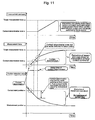
Fig. 9 , in terms of improvement of measurement efficiency, the probe is desired to follow shape variation, as fast as possible, of the object to be measured. Accordingly, it is required to set a loop gain of a force control loop high and to make high-response. In this state, when the first embodiment is applied, as shown inFig. 10 , impact increase and over-shoot occur due to the high response, and there is a possibility that the contact trace remains on the object to be measured. - In order to solve such problems of the first embodiment, in a second embodiment of the present invention, as shown in
Fig. 11 , a force control command when the position control is switched to the force control is not raised at once to the target measurement force, but interpolated and gradually raised so as to approach the target measurement force. Thus, the impact and the over-shoot in contact are reduced, and the contact trace can be prevented from occurring. -
Fig. 12 shows a constitutional example of a probe system of the embodiment. - The probe system is different from the probe system shown in
Fig. 9 in the point that a force control command interpolation processing part for subjecting the target measurement force to interpolation processing and making it into the force control command is provided in the digitalcontrol calculating part 48. The system is similar to that shown inFig. 9 in other points, therefore, description of the points is omitted. - Here, occurrence of the contact trace on the object to be measured depends on conditions such as properties, such as shape and hardness, of a contact part of the force sensor, approach speed, magnitude of impact in contact, properties such as hardness of a surface of the obj ect to be measured, control performance of the position control and control performance of the force control. Thus, force control command interpolation processing may include the following performances.
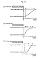
- That is, as shown in
Fig. 13 , an interpolation curve of the force control command can be selected and used from arbitrary curves. InFig. 11 , the interpolation curve is shown by a straight line connecting the contact determination level and the target measurement force as shown inFig. 13(a) . However, interpolation curves of various types such as the exponent type shown inFig. 13(b) , S-curve type shown inFig. 13 (c) and the like can be used, the interpolation curve being used for an acceleration curve of the position control, and can be arbitrarily selected in accordance with a measurement condition or the like. - In the case of the linear type interpolation curve in
Fig. 13(a) , control is simple. On the other hand, in the case of the S-curve type interpolation curve inFig. 13(c) being used, calculation is difficult, but extremely smooth control can be performed.
Additionally, in the exponent type interpolation curve inFig. 13(b) , control can be performed more smoothly than that when the linear type interpolation curve inFig. 13(a) is used, and calculation can be performed more easily than that when the S-curve type interpolation curve inFig. 13(c) is used. - Additionally, an interpolation time T of shift from the contact determination level to the target measurement force can be arbitrarily selected, the time being shown in
Fig. 13 . For example, in the case of an object to be measured on which a contact trace easily occurs, the interpolation time is lengthened, and in the case of an object to be measured on which a contact trace hardly occurs, the interpolation time is shortened. Thus, the measurement efficiency can be raised. - Alternatively, in place of the interpolation time, increase (inclination) of force for unit time may be set like the acceleration command of the position control.
- Auser thus can select a proper interpolation processing in accordance with properties of the obj ect to be measured, and can perform approach operation excellent in the measurement efficiency without causing a contact trace.
- Moreover, though the applicant used, in the embodiments, the force sensor disclosed in
patent document 1, a probe of the present invention is not limited thereto. The present invention can be similarly applied to any probe as long as it can observe fine measurement force. Additionally, the probe system is not limited to a digital constitution.
Claims (10)
- A profiling controlling method for contact type probes, in which a contact point is moved along a surface of an object to be measured, while being in contact with the object by a specified measurement force, comprising the steps of:providing a contact determination level for detecting a predetermined force smaller than a target measurement force is applied to the contact point;performing contact determination at the time when force applied to the contact point reaches the contact determination level during approach; andshifting the contact point from position control to force control for bringing the contact point into contact with the object by the target measurement force.
- The profiling controlling method for contact type probes according to claim 1, wherein
the predetermined force is a force at which contact can be considered to be predicted for the object to be measured and the contact point begins. - The profiling controlling method for contact type probes according to claim 1, wherein
speed of the approach is selected so as to satisfy the following inequality:(push-in amount at contact determination level+ push-in amount by delay time of contact determination)≤ push-in amount by measurement force. - The profiling controlling method for contact type probes according to claim 1, wherein a
a command value of force control is interpolated and gradually increased from the contact determination level to the target measurement force. - The profiling controlling method for contact type probes according to claim 4, wherein
an interpolation curve of the force control command value is linear. - The profiling controlling method for contact type probes according to claim 4, wherein
the interpolation curve of the force control command value is an exponent type. - The profiling controlling method for contact type probes according to claim 4, wherein
the interpolation curve of the force control command value is a S-curve type. - The profiling controlling method for contact type probes according to claim 4, wherein
an interpolation time of the force control command value is variable. - A profiling controller for contact type probes, in which a contact point is moved along a surface of an object to be measured, while being in contact with the object by a specified measurement force, the controller comprising:contact detecting means for detecting a predetermined contact determination level force lower than a target measurement force is applied to the contact point;position controlling means for controlling a position of the contact point;force controlling means for controlling measurement force applied to the contact point; andmeans for performing contact determination at the time when the force applied to the contact point reaches the contact determination level during approach, and shifting the contact point from position control to force control for bringing the contact point into contact with the object by the target measurement force.
- A contact type measuring machine comprising a contact type probe profiling-controlled by the controller of claim 9.
Applications Claiming Priority (1)
| Application Number | Priority Date | Filing Date | Title |
|---|---|---|---|
| JP2007032933A JP5199582B2 (en) | 2007-02-14 | 2007-02-14 | Contact probe scanning control method and contact measuring machine |
Publications (3)
| Publication Number | Publication Date |
|---|---|
| EP1959230A2 true EP1959230A2 (en) | 2008-08-20 |
| EP1959230A3 EP1959230A3 (en) | 2008-09-03 |
| EP1959230B1 EP1959230B1 (en) | 2011-07-27 |
Family
ID=39363970
Family Applications (1)
| Application Number | Title | Priority Date | Filing Date |
|---|---|---|---|
| EP08001246A Ceased EP1959230B1 (en) | 2007-02-14 | 2008-01-23 | Method and apparatus for controlling the contact type probe of a profile measuring machine |
Country Status (3)
| Country | Link |
|---|---|
| US (1) | US7769560B2 (en) |
| EP (1) | EP1959230B1 (en) |
| JP (1) | JP5199582B2 (en) |
Families Citing this family (6)
| Publication number | Priority date | Publication date | Assignee | Title |
|---|---|---|---|---|
| WO2012037059A1 (en) * | 2010-09-13 | 2012-03-22 | Hexagon Technology Center Gmbh | Method and apparatus for controlling a surface scanning coordinate measuring machine |
| JP2013007669A (en) * | 2011-06-24 | 2013-01-10 | Ulvac Japan Ltd | Stylus jump suppression method in stylus type step profiler for surface shape measurement |
| EP2642242B1 (en) | 2012-03-22 | 2020-01-08 | Balance Systems S.r.L. | Measuring device including feeler for workpieces |
| TWI724696B (en) | 2019-12-18 | 2021-04-11 | 財團法人工業技術研究院 | Workpiece hole measurement method |
| CN111459324B (en) * | 2020-03-30 | 2023-06-30 | 北京工业大学 | An Ultrasonic Lamb Wave Touch Screen |
| CN114994372A (en) * | 2022-05-25 | 2022-09-02 | 广东江粉高科技产业园有限公司 | Center positioning device of test touch-control response volume tool |
Citations (1)
| Publication number | Priority date | Publication date | Assignee | Title |
|---|---|---|---|---|
| EP1669739A1 (en) | 2004-12-10 | 2006-06-14 | Fuji Photo Film Co., Ltd | Optical tomography apparatus |
Family Cites Families (10)
| Publication number | Priority date | Publication date | Assignee | Title |
|---|---|---|---|---|
| JPH11316119A (en) * | 1998-05-06 | 1999-11-16 | Ricoh Co Ltd | Contact load control device and shape measuring device using the same |
| JP4557466B2 (en) * | 2001-08-02 | 2010-10-06 | キヤノン株式会社 | Contact probe |
| JP2003097938A (en) * | 2001-09-21 | 2003-04-03 | Ricoh Co Ltd | Control device, control method, shape measuring device, and robot |
| JP2003097939A (en) * | 2001-09-21 | 2003-04-03 | Ricoh Co Ltd | Shape measuring device, shape measuring method, storage medium for storing computer program for shape measuring and computer program for shape measuring, shape correcting / processing method, mold for shape transfer, molded product, and optical system |
| JP3961258B2 (en) * | 2001-10-10 | 2007-08-22 | 株式会社ミツトヨ | Touch sensor and probe for fine shape measuring device |
| JP2004077307A (en) * | 2002-08-20 | 2004-03-11 | Canon Inc | Switching method of control method |
| JP2005069972A (en) * | 2003-08-27 | 2005-03-17 | Hitachi Kenki Fine Tech Co Ltd | Probe movement control method for scanning probe microscope |
| JP2006078354A (en) * | 2004-09-10 | 2006-03-23 | Canon Inc | Probe control device and shape measuring device |
| JP4909548B2 (en) * | 2005-09-01 | 2012-04-04 | 株式会社ミツトヨ | Surface shape measuring device |
| JP2007309684A (en) * | 2006-05-16 | 2007-11-29 | Mitsutoyo Corp | Measurement controller, surface property measuring instrument, and measurement control method |
-
2007
- 2007-02-14 JP JP2007032933A patent/JP5199582B2/en not_active Expired - Fee Related
-
2008
- 2008-01-23 EP EP08001246A patent/EP1959230B1/en not_active Ceased
- 2008-01-30 US US12/022,556 patent/US7769560B2/en active Active
Patent Citations (1)
| Publication number | Priority date | Publication date | Assignee | Title |
|---|---|---|---|---|
| EP1669739A1 (en) | 2004-12-10 | 2006-06-14 | Fuji Photo Film Co., Ltd | Optical tomography apparatus |
Also Published As
| Publication number | Publication date |
|---|---|
| EP1959230A3 (en) | 2008-09-03 |
| JP2008196983A (en) | 2008-08-28 |
| JP5199582B2 (en) | 2013-05-15 |
| EP1959230B1 (en) | 2011-07-27 |
| US7769560B2 (en) | 2010-08-03 |
| US20080195353A1 (en) | 2008-08-14 |
Similar Documents
| Publication | Publication Date | Title |
|---|---|---|
| US7769560B2 (en) | Profiling controlling method and controller for contact type probes, and contact type measuring machine | |
| US7318285B2 (en) | Surface profile measuring instrument | |
| EP1865281B1 (en) | Surface texture measuring instrument | |
| US7159452B2 (en) | Method for measuring a configuration of an object | |
| US8131385B2 (en) | Positioning device and positioning method with non-contact measurement | |
| US9791330B2 (en) | Device and method for measuring a change in length of a sample and/or for measuring a deformation force on a sample | |
| JPS6321841B2 (en) | ||
| JP2017024108A (en) | Machine tool thermal displacement correction apparatus | |
| JP3836964B2 (en) | J1C test load control method for test piece and J1C test system | |
| CN112444229B (en) | Shape measuring device, reference device and calibration method of detector | |
| US7756672B2 (en) | Method for setting a predetermined distance between a machine tool and an electrically conductive workpiece | |
| US20230288900A1 (en) | Numerical control device | |
| JP2018179824A (en) | Scanning probe microscope | |
| US20250067769A1 (en) | Scanning probe microscopy system and method of operating such a system | |
| JP2008032540A (en) | Surface shape measuring apparatus and method for detecting anomaly of stylus load | |
| JP2003166927A (en) | Scanning probe microscope | |
| JP7530272B2 (en) | Shape measuring device and abnormality detection method | |
| JP2007121146A (en) | Surface roughness/shape-measuring apparatus and program for controlling the same | |
| JP2020067443A (en) | Shape measurement device and shape measurement method | |
| JPH08219752A (en) | Shape measuring device | |
| JP2007304037A (en) | Shape measuring device | |
| JP2009031242A (en) | Positioning control system |
Legal Events
| Date | Code | Title | Description |
|---|---|---|---|
| PUAI | Public reference made under article 153(3) epc to a published international application that has entered the european phase |
Free format text: ORIGINAL CODE: 0009012 |
|
| PUAL | Search report despatched |
Free format text: ORIGINAL CODE: 0009013 |
|
| AK | Designated contracting states |
Kind code of ref document: A2 Designated state(s): AT BE BG CH CY CZ DE DK EE ES FI FR GB GR HR HU IE IS IT LI LT LU LV MC MT NL NO PL PT RO SE SI SK TR |
|
| AX | Request for extension of the european patent |
Extension state: AL BA MK RS |
|
| AK | Designated contracting states |
Kind code of ref document: A3 Designated state(s): AT BE BG CH CY CZ DE DK EE ES FI FR GB GR HR HU IE IS IT LI LT LU LV MC MT NL NO PL PT RO SE SI SK TR |
|
| AX | Request for extension of the european patent |
Extension state: AL BA MK RS |
|
| 17P | Request for examination filed |
Effective date: 20090303 |
|
| 17Q | First examination report despatched |
Effective date: 20090403 |
|
| AKX | Designation fees paid |
Designated state(s): DE FR GB |
|
| GRAP | Despatch of communication of intention to grant a patent |
Free format text: ORIGINAL CODE: EPIDOSNIGR1 |
|
| RIC1 | Information provided on ipc code assigned before grant |
Ipc: G01B 21/04 20060101ALI20110120BHEP Ipc: G01B 7/012 20060101AFI20110120BHEP |
|
| RAP1 | Party data changed (applicant data changed or rights of an application transferred) |
Owner name: MITUTOYO CORPORATION |
|
| GRAS | Grant fee paid |
Free format text: ORIGINAL CODE: EPIDOSNIGR3 |
|
| GRAA | (expected) grant |
Free format text: ORIGINAL CODE: 0009210 |
|
| AK | Designated contracting states |
Kind code of ref document: B1 Designated state(s): DE FR GB |
|
| REG | Reference to a national code |
Ref country code: GB Ref legal event code: FG4D |
|
| REG | Reference to a national code |
Ref country code: DE Ref legal event code: R096 Ref document number: 602008008453 Country of ref document: DE Effective date: 20110915 |
|
| PLBE | No opposition filed within time limit |
Free format text: ORIGINAL CODE: 0009261 |
|
| STAA | Information on the status of an ep patent application or granted ep patent |
Free format text: STATUS: NO OPPOSITION FILED WITHIN TIME LIMIT |
|
| 26N | No opposition filed |
Effective date: 20120502 |
|
| REG | Reference to a national code |
Ref country code: DE Ref legal event code: R097 Ref document number: 602008008453 Country of ref document: DE Effective date: 20120502 |
|
| REG | Reference to a national code |
Ref country code: FR Ref legal event code: PLFP Year of fee payment: 9 |
|
| REG | Reference to a national code |
Ref country code: FR Ref legal event code: PLFP Year of fee payment: 10 |
|
| REG | Reference to a national code |
Ref country code: FR Ref legal event code: PLFP Year of fee payment: 11 |
|
| PGFP | Annual fee paid to national office [announced via postgrant information from national office to epo] |
Ref country code: DE Payment date: 20220119 Year of fee payment: 15 |
|
| PGFP | Annual fee paid to national office [announced via postgrant information from national office to epo] |
Ref country code: FR Payment date: 20230124 Year of fee payment: 16 |
|
| PGFP | Annual fee paid to national office [announced via postgrant information from national office to epo] |
Ref country code: GB Payment date: 20230119 Year of fee payment: 16 |
|
| REG | Reference to a national code |
Ref country code: DE Ref legal event code: R119 Ref document number: 602008008453 Country of ref document: DE |
|
| PG25 | Lapsed in a contracting state [announced via postgrant information from national office to epo] |
Ref country code: DE Free format text: LAPSE BECAUSE OF NON-PAYMENT OF DUE FEES Effective date: 20230801 |
|
| GBPC | Gb: european patent ceased through non-payment of renewal fee |
Effective date: 20240123 |
|
| PG25 | Lapsed in a contracting state [announced via postgrant information from national office to epo] |
Ref country code: GB Free format text: LAPSE BECAUSE OF NON-PAYMENT OF DUE FEES Effective date: 20240123 |
|
| PG25 | Lapsed in a contracting state [announced via postgrant information from national office to epo] |
Ref country code: FR Free format text: LAPSE BECAUSE OF NON-PAYMENT OF DUE FEES Effective date: 20240131 |
|
| PG25 | Lapsed in a contracting state [announced via postgrant information from national office to epo] |
Ref country code: GB Free format text: LAPSE BECAUSE OF NON-PAYMENT OF DUE FEES Effective date: 20240123 Ref country code: FR Free format text: LAPSE BECAUSE OF NON-PAYMENT OF DUE FEES Effective date: 20240131 |