EP1959094B1 - Lochauskleidungen zur Reparatur von Leitschaufelringbohrlöchern von verstellbaren Leitschaufeln - Google Patents
Lochauskleidungen zur Reparatur von Leitschaufelringbohrlöchern von verstellbaren Leitschaufeln Download PDFInfo
- Publication number
- EP1959094B1 EP1959094B1 EP08250529A EP08250529A EP1959094B1 EP 1959094 B1 EP1959094 B1 EP 1959094B1 EP 08250529 A EP08250529 A EP 08250529A EP 08250529 A EP08250529 A EP 08250529A EP 1959094 B1 EP1959094 B1 EP 1959094B1
- Authority
- EP
- European Patent Office
- Prior art keywords
- liner
- counterbore
- shroud
- hole
- vane
- Prior art date
- Legal status (The legal status is an assumption and is not a legal conclusion. Google has not performed a legal analysis and makes no representation as to the accuracy of the status listed.)
- Active
Links
Images


Classifications
-
- F—MECHANICAL ENGINEERING; LIGHTING; HEATING; WEAPONS; BLASTING
- F01—MACHINES OR ENGINES IN GENERAL; ENGINE PLANTS IN GENERAL; STEAM ENGINES
- F01D—NON-POSITIVE DISPLACEMENT MACHINES OR ENGINES, e.g. STEAM TURBINES
- F01D17/00—Regulating or controlling by varying flow
- F01D17/10—Final actuators
- F01D17/12—Final actuators arranged in stator parts
- F01D17/14—Final actuators arranged in stator parts varying effective cross-sectional area of nozzles or guide conduits
- F01D17/16—Final actuators arranged in stator parts varying effective cross-sectional area of nozzles or guide conduits by means of nozzle vanes
- F01D17/162—Final actuators arranged in stator parts varying effective cross-sectional area of nozzles or guide conduits by means of nozzle vanes for axial flow, i.e. the vanes turning around axes which are essentially perpendicular to the rotor centre line
-
- B—PERFORMING OPERATIONS; TRANSPORTING
- B23—MACHINE TOOLS; METAL-WORKING NOT OTHERWISE PROVIDED FOR
- B23P—METAL-WORKING NOT OTHERWISE PROVIDED FOR; COMBINED OPERATIONS; UNIVERSAL MACHINE TOOLS
- B23P6/00—Restoring or reconditioning objects
- B23P6/002—Repairing turbine components, e.g. moving or stationary blades, rotors
- B23P6/005—Repairing turbine components, e.g. moving or stationary blades, rotors using only replacement pieces of a particular form
-
- F—MECHANICAL ENGINEERING; LIGHTING; HEATING; WEAPONS; BLASTING
- F04—POSITIVE - DISPLACEMENT MACHINES FOR LIQUIDS; PUMPS FOR LIQUIDS OR ELASTIC FLUIDS
- F04D—NON-POSITIVE-DISPLACEMENT PUMPS
- F04D29/00—Details, component parts, or accessories
- F04D29/40—Casings; Connections of working fluid
- F04D29/52—Casings; Connections of working fluid for axial pumps
- F04D29/522—Casings; Connections of working fluid for axial pumps especially adapted for elastic fluid pumps
- F04D29/526—Details of the casing section radially opposing blade tips
-
- F—MECHANICAL ENGINEERING; LIGHTING; HEATING; WEAPONS; BLASTING
- F04—POSITIVE - DISPLACEMENT MACHINES FOR LIQUIDS; PUMPS FOR LIQUIDS OR ELASTIC FLUIDS
- F04D—NON-POSITIVE-DISPLACEMENT PUMPS
- F04D29/00—Details, component parts, or accessories
- F04D29/40—Casings; Connections of working fluid
- F04D29/52—Casings; Connections of working fluid for axial pumps
- F04D29/54—Fluid-guiding means, e.g. diffusers
- F04D29/56—Fluid-guiding means, e.g. diffusers adjustable
- F04D29/563—Fluid-guiding means, e.g. diffusers adjustable specially adapted for elastic fluid pumps
-
- F—MECHANICAL ENGINEERING; LIGHTING; HEATING; WEAPONS; BLASTING
- F05—INDEXING SCHEMES RELATING TO ENGINES OR PUMPS IN VARIOUS SUBCLASSES OF CLASSES F01-F04
- F05D—INDEXING SCHEME FOR ASPECTS RELATING TO NON-POSITIVE-DISPLACEMENT MACHINES OR ENGINES, GAS-TURBINES OR JET-PROPULSION PLANTS
- F05D2230/00—Manufacture
- F05D2230/80—Repairing, retrofitting or upgrading methods
-
- F—MECHANICAL ENGINEERING; LIGHTING; HEATING; WEAPONS; BLASTING
- F05—INDEXING SCHEMES RELATING TO ENGINES OR PUMPS IN VARIOUS SUBCLASSES OF CLASSES F01-F04
- F05D—INDEXING SCHEME FOR ASPECTS RELATING TO NON-POSITIVE-DISPLACEMENT MACHINES OR ENGINES, GAS-TURBINES OR JET-PROPULSION PLANTS
- F05D2240/00—Components
- F05D2240/10—Stators
- F05D2240/14—Casings or housings protecting or supporting assemblies within
Definitions
- the present invention is related to gas turbine engines, and in particular to variable vane counterbored holes on vane shrouds and to methods for repairing such a damaged counterbore hole.
- Gas turbine engines operate by combusting fuel in compressed air to create heated gases with increased pressure and density.
- the heated gases are ultimately forced through an exhaust nozzle, which is used to step up the velocity of the exiting gases and in-turn produce thrust for driving an aircraft.
- turbofan engines the heated gases are used to drive a turbine for rotating a fan to produce thrust, and to drive a turbine for driving a compressor that provides the compressed air used during combustion.
- the compressor section of a gas turbine engine typically comprises a series of rotor blade and stator vane stages. At each stage, rotating blades push air past the stationary vanes. Each rotor/stator stage increases the pressure and density of the air. Stators convert the kinetic energy of the air into pressure, and they redirect the trajectory of the air coming off the rotors for flow into the next compressor stage.
- the speed range of an aircraft powered by a gas turbine engine is directly related to the level of air pressure generated in the compressor section.
- the velocity of the airflow through the gas turbine engine varies.
- the incidence of the air onto rotor blades of subsequent compressor stages differs at different aircraft speeds.
- One way of achieving more efficient performance of the gas turbine engine over the entire speed range, especially at high speed/high pressure ranges, is to use variable stator vanes which can optimize the incidence of the airflow onto subsequent compressor stage blades.
- variable stator vanes are typically circumferentially arranged between outer and inner diameter shrouds, which are typically manufactured from steel alloys.
- the vanes typically include trunnion posts at their innermost and outermost diameters that extend through counterbored holes in the shrouds, respectively. Accordingly, it is desirable that the variable vanes have low-friction rotational movement within the counterbores.
- these counterbores become worn and weathered. In addition to normal vane-induced wear, operation in wet and/or salt-rich environments induces corrosion or pitting in the counterbores, which interferes with free rotation of the vane trunnions within the counterbores.
- variable vane counterbored holes In the case of severe wear or corrosion, it can be necessary to replace the entire compressor case or vane shroud in order to restore optimal free rotation to the variable vanes. This is undesirable because these parts are typically very costly due to the high-grade alloys and precision manufacturing necessary to produce these parts. Thus, there is a need for improved methods and systems for reducing or eliminating the effects of wear and corrosion on variable vane counterbored holes.
- EP-1400659 which constitutes the closest prior art, discloses a vane shroud having a cylindrical shaped body, a hole, a counterbore and liner inserted into the hole and counterbore, and a repair method of such a vane shroud.
- a vane shroud for a gas turbine engine as claimed in claim 1 and a method for repairing a damaged counterbore in a variable vane shroud as claimed in claim 9.
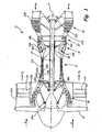
- FIG. 1 shows gas turbine engine 10, in which variable vane hole liners are used.
- Gas turbine engine 10 comprises a dual-spool turbofan engine having variable stator vanes for which the advantages of the hole liners are particularly well illustrated.
- Gas turbine engine 10 comprises fan 12, low pressure compressor (LPC) 14, high pressure compressor (HPC) 16, combustor section 18, high pressure turbine (HPT) 20 and low pressure turbine (LPT) 22, which are each concentrically disposed around longitudinal engine centerline CL.
- Fan 12 is enclosed at its outer diameter within fan case 23A.
- the other engine components are correspondingly enclosed at their outer diameters within various engine casings, including LPC case 23B, HPC case 23C, HPT case 23D and LPT case 23E such that an air flow path is formed around centerline CL.
- Inlet air A enters engine 10 and it is divided into streams of primary air A P and secondary air As after it passes through fan 12.
- Fan 12 is rotated by low pressure turbine 22 through shaft 24 to accelerate secondary air As (also known as bypass air) through exit guide vanes 26, thereby producing a major portion of the thrust output of engine 10.
- Shaft 24 is supported within engine 10 at ball bearing 25A, roller bearing 25B and roller bearing 25C.
- Primary air A P (also known as gas path air) is directed first into low pressure compressor (LPC) 14 and then into high pressure compressor (HPC) 16.
- LPC 14 and HPC 16 work together to incrementally step up the pressure of primary air A P .
- HPC 16 is rotated by HPT 20 through shaft 28 to provide compressed air to combustor section 18.
- Shaft 28 is supported within engine 10 at ball bearing 25D and roller bearing 25E.
- the compressed air is delivered to combustors 18A and 18B, along with fuel through injectors 30A and 30B, such that a combustion process can be carried out to produce the high energy gases necessary to turn turbines 20 and 22.
- Primary air A P continues through gas turbine engine 10 whereby it is typically passed through an exhaust nozzle to further produce thrust.
- variable stator vanes are used in high pressure compressor 16.
- HPC 16 comprises variable vanes 32A and 32B, which are stationary and extend radially inward from fan case 23C.
- Blades 34A and 34B which rotate with HPC 16 on shaft 28, are positioned adjacent vanes 32A and 32B.
- Vanes 32A and 32B form part of an array of vane stages arranged circumferentially around the engine centerline between HPC case 23C and an inner diameter vane shroud. Blades 34A and 34B sequentially push primary air A P past vanes 32A and 32B within HPC 16 to increase the pressure of primary air A P .
- Vanes 32A and 32B rotate about their radial axis to adjust the incidence of the air A P onto subsequent blades, including blade 34B, during different operation modes, or speeds, of engine 10. In order to ensure optimal operation of engine 10, it is preferable that vanes 32A and 32B are able to rotate freely about their axis within HPC case 23C and the inner diameter vane shroud.
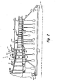
- FIG. 2 shows the sequential arrangement of the various stages of high pressure compressor 16 about centerline CL of gas turbine engine 10.
- HPC 16 is divided into stages S5 through S15, with LPC 14 of FIG. 1 comprising stages S1 through S4.
- Vanes 32A and 32B and blades 34A and 34B comprise stages S6 and S7 of HPC 16, respectively.
- the variable vanes rotate between HPC case 23C and a plurality of inner diameter vane shrouds.
- vanes 32A and 32B rotate between HPC outer shroud 36, which is a component of case 23C, and HPC inner shrouds 38A and 38B, respectively.
- vanes 32A and 32B are connected to sync rings 40A and 40B, respectively, through a plurality of sync arms 42.
- Sync rings 40A and 40B are connected to, for example, a hydraulic actuator to adjust the pitch of vanes 32A and 32B such that airflow through HPC 16 is optimized for different operating levels of engine 10.
- vanes 32A and 32B include inner and outer diameter trunnions.
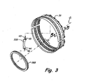
- FIG. 3 shows an exploded view of variable vane 32B positioned between outer vane shroud 36 and inner vane shroud 38B.
- Outer vane shroud 36 and inner vane shroud 38B are positioned concentrically around engine centerline CL at the inner and outer diameters of vane 32B, respectively.
- Vane shroud 36 comprises a conically shaped body that surrounds stages S6 and S7 of HPC 16, including vanes 32A and 32B and blades 34A and 34B.
- Vane shroud 36 typically comprises a split-ring construction wherein it is divided into upper and lower halves.
- Vane 32B includes outer trunnion 43 and inner trunnion 44 that rotate within variable vane counterbored holes. Using sync ring 40B and sync arms 42 as shown in FIG. 2 , vane 32B is rotatable about trunnions 43 and 44 within the counterbored holes in outer vane shroud 36 and inner vane shroud 38B. Additionally, trunnions may include additional features for assisting in true rotation of the variable vanes. For example, vane 32B includes outer diameter hub 45 and inner diameter hub 46 that rotate within the counterbores surrounding the counterbored trunnion holes and help to keep vanes 32B properly aligned. Vane 32A is configured similarly to vane 32B.
- the counterbores become damaged or worn from use and weather, thus impeding the free rotation of trunnions 43 and 44 within the counterbores, and hubs 45 and 46 against the counterbores. Impediments to the rotation of vanes 32A and 32B can lead to misalignment of the vane pitch along the flow path of engine 10 resulting in sub-optimal operation of HPC 16 and engine 10.
- the counterbores begin to show wear after one engine overhaul cycle, with extensive damage appearing typically after 2 - 3 engine overhaul cycles.
- the present invention provides a system and method for repairing counterbored holes, principally for variable vanes.
- the repair system and method includes a counterbored hole liner, which can be included in new engine components or can be retrofit into engine components as a fix to damage already sustained.
- a counterbored hole liner which can be included in new engine components or can be retrofit into engine components as a fix to damage already sustained.
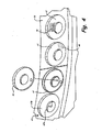
- FIG. 4 shows breakout portion A of FIG. 3 , showing a perspective view of vane bottom counterbored holes 47, in outer vane shroud 36.
- Outer vane shroud 36 includes counterbored holes 47 that each receives an outer diameter trunnion from a variable vane, such as trunnion 43 from vane 32B.
- Counterbored holes 47 comprise hole 47A, which is surrounded by counterbore 47B.
- Counterbored holes 47 are machined to original design dimensions, free of any pitting, wear or corrosion.
- vane counterbored holes 47 become damaged such that rotation of hub 45 and trunnion 43 is hampered.
- counterbored holes 47 develop corrosion 48 that arises from harsh operating conditions of engine 10.
- Corrosion 48 includes pitting or other structural deficiencies of the base material comprising vane shroud 36, which is typically a steel alloy such as an Austenitic steel or another iron-based alloy that builds up oxide layers leading to corrosion. Corrosion 48 arises from the extreme temperatures at which engine 10 operates and other external factors such as salt-rich operational environments. Counterbored holes 47 also develop scoring 50 that arises from routine rotation of trunnion 43 and hub 45 within counterbored holes 47. Corrosion 48 and scoring 50 prevent free rotation of hub 45 on the surface of the counterbore into which they are inserted. As such counterbored holes 47 are provided with hole liner 52. Counterbored holes 47 are over-bored such that any damage is removed from the base material of shroud 36. Subsequently, liner 52, having dimensions matching that of the removed over-bore, is inserted into counterbored holes 47 to restore shroud 36 to original specifications.
- hole liner 52 having dimensions matching that of the removed over-bore, is inserted
- FIG. 5 shows cross section 5-5 of FIG. 3 showing the insertion of counterbored hole liner 52 into outer diameter shroud 36 of HPC case 23C.
- Outer diameter shroud 36 includes counterbored holes 54A and 54B for receiving trunnions of variable vanes.
- Counterbored holes 54A and 54B each comprise a trunnion hole 55A and 55B, respectively, extending through shroud 36 and a corresponding counterbore 56A and 56B, respectively, surrounding trunnion holes 55A and 55B, respectively.
- Outer diameter shroud 36 also includes trenches 57A and 57B against which the outer diameter ends of blades 34A and 34B engage.
- trenches 57A and 57B are filled with a plasma-sprayed abradable material.
- counterbored hole 54B receives trunnion 43 and hub 45 of vane 32B.
- shroud 36 is provided with a variable vane hole liner.
- liner 52 which is an exemplary embodiment of the hole liners, is used in conjunction with counterbored hole 54B.
- Vane shroud 36 is generally a conically shaped cylinder such that it is disposed around engine centerline CL with a sloping orientation. Forward end 58 of shroud 36 is disposed length L 1 away from centerline CL, whereas aft end 60 is disposed length L 2 away from centerline CL. Length L 1 is greater than length L 2 such that radially innermost surface 62 of shroud 36 slopes toward centerline CL as shroud 36 extends from forward end 58 to aft end 60.
- counterbores 56A and 56B include flat surfaces 64A and 64B, respectively.
- counterbores 56A and 56B are machined perpendicularly to centerline CL into surface 62.
- counterbores 56A and 56B include walls 66A and 66B that are cylindrically shaped and extend from the generally flat surfaces 64A and 64B to the conically shaped surface 62 such that walls 66A and 66B follow the contour of surface 62.
- Shroud 36 is typically produced as a single-piece unitary component. Thus, shroud 36 is finished to meet final dimensional tolerances, including the final dimensions of counterbored holes 54A and 54B. Counterbored holes 54A and 54B are typically finished such that they receive trunnion 43 and hub 45 with fairly tight tolerances such that slop is eliminated from the system, depending on design needs. However, due to damage imparted by corrosion and wear discussed above, the dimensions and tolerances of counterbored holes 54A and 54B become altered such that smooth rotation of trunnion 43 and hub 45 is affected. As such, shroud 36 is repaired with hole liner 52.
- FIG. 6A shows a top perspective view of liner 52
- FIG. 6B shows a bottom perspective view of liner 52
- Liner 52 is constructed such that counterbored hole 54B can be milled out, or over-bored, to remove the corrosion or damage to counterbored hole 54B.
- Liner 52 includes flat floor 68, wall 70 and neck 72. As can be seen, wall 70 has a sloping shape that varies around its edge perimeter to match the contour of surface 62.
- Liner 52 may be comprised of any material suitable for withstanding the thermal and mechanical stresses associated with shroud 36 during operation of engine 10.
- liner 52 is made from a metallic alloy or from an engineered plastic. Any suitable alloy can be used, however, alloys matching that of shroud 36 are particularly suitable.
- Austenitic stainless steels such as 300 series stainless; or nickel materials, such as the Inconel family, would also be suitable materials.
- Polyetheretherketone (PEEK) materials such as Sustatec ® PEEK as is commercially available from Sustaplast, L.P., Edgewood, NY; or PTFE-based materials, such as Rulon ® 945 as is commercially available from St.
- Gobain Performance Plastics, Valley Forge, PA are examples of suitable engineered plastics.
- Rulon 957, also available from St. Gobain, is another suitable material.
- desirable properties include heat resistance, low friction and strength.
- corrosion resistant material may be selected to reduce recurrence of corrosion damage.
- Low-friction materials may be selected such that the variable vanes are better able to rotate.
- the material for liner 52 may be selected to have a lower coefficient of friction than that of the material comprising shroud 36. It is preferable that materials be able to sustain temperatures upwards of 600° F (316°C), preferably up to about 700° F (371°C), which are temperatures commonly reached around HPC 16. It is also desirable to match the thermal expansion rate of the material of liner 52 with that of the material comprising shroud 36.
- the qualities for shroud 36 can be selected to match design needs depending on performance parameters of engine 10.
- FIG. 7 shows a close-up view of liner 52 for insertion into counterbored hole 54B of outer diameter vane shroud 36.
- Counterbored hole 54B is machined into shroud 36 such that it is made to specification as is required by design parameters.
- Counterbored hole 54B extends into shroud 36 such that it is shown in dotted line D in FIG. 7 .
- Counterbored hole 54B includes neck 74, base 76 and wall 78.
- counterbored hole 54B undergoes corrosion and wear such that shroud 36 becomes damaged. The damage associated with the corrosion or wear extends into the base material of shroud 36 a particular depth.
- counterbored hole 54B is machined out, or over-bored, a particular depth to remove the damaged base material such as shown in solid lines in FIG. 7 .
- it is not enough to simply remove the damaged material as any material removal of shroud 36 permits slop in the rotation of vane 32B, which affects the efficiency of HPC 16.
- a uniform amount of material is removed from counterbored hole 54B such that it can be readily replaced to restore shroud 36 to its original design dimensions.
- Liner 52 is inserted into the over-bored counterbored hole 54B to restore shroud 36 and counterbored hole 54B to their original dimensions.
- liner 52 is made to dimensions that match the amount of material removed from counterbored hole 54B in removing the damaged base material.
- Wear and corrosion may occur anywhere along counterbored hole 54B.
- wall 78 undergoes wear and corrosion such that it becomes damaged to some depth less than or equal to depth t 1 .
- material is uniformly removed from the entirety of wall 78 to depth t 1 to ensure all damaged material is removed.
- Wall 70 of liner 52 is correspondingly manufactured to have a thickness corresponding to depth t 1 .
- material is removed from around neck 74 and floor 76 to a depth necessary to remove any damaged base material at those locations.
- liner 52 is fabricated such that neck 72 and floor 68 have thicknesses matching the amount of material removed from neck 74 and floor 76, which may or may not equal depth t 1 .
- material may be uniformly removed from neck 74, floor 76 and wall 78 to a depth necessary to remove the deepest damage on counterbore 54B, regardless of the location of the damage.
- the least amount of material as is practically possible is removed from shroud 36 such that shroud 36 is not thinned-out too much and its structural integrity is not compromised, as the thickness of shroud 36 is generally on the order of about 0.04 inches ( ⁇ 0.1016 cm).
- the invention is particularly well suited to shallow damage incurred to counterbored hole 54B.
- floor 76 has additional material removed to form a void or locating recess 80.
- Liner 52 is thus fabricated with corresponding button 82 that comprises the negative shape of recess 80 and is positioned on floor 68 on a corresponding location.
- Locating recess 80 is positioned on floor 76 such that liner 52 can be properly inserted into counterbored hole 54B in only one way. This is particularly advantageous since wall 70 of liner 52 is of varying height to match the varying height of wall 78. Liner 52 would be difficult to rotate within counterbored hole 54B when fully seated due to its thin construction.
- button 82 prevents liner 52 from becoming fully seated within counterbored hole 54B unless wall 70 is aligned with the slope of wall 78. Also, button 82 prevents any rotation of liner 52 during any processes used to secure liner 52 to shroud 36.
- Liner 52 may be secured to shroud 36 in any suitable manner.
- liner 52 may be welded, brazed or glued to shroud 36.
- liner 52 is furnace brazed using a foil bonding material.
- liner 52 is resistance welded to shroud 36 at surface 84.
- spot welding or electron beam welding would be suitable, however subsequent machining steps would be needed to remove slag or any other byproducts.
- shroud 36 and liner 52 can be heat treated to reduce any stress risers produced during the welding process. Regardless of the method selected for securing liner 52 to shroud 36, it is preferable that no subsequent machining steps are required.
- high temperature adhesives or glues would be suitable methods for securing liner 52 to shroud 36.
- liner 52 provides an easy, low-cost repair means for repairing variable vane counterbored holes. Repairs following the present invention can be made at most overhaul or repair shops as the repair can be carried out using commonly found equipment such as a mill or welding equipment. Expensive or elaborate equipment, such as a plasma-spray booth, is not required. Also, the invention allows for different repairs to be made to cure the same deficiencies such that each shop can perform a repair method within their capabilities. Also, the present invention allows for selective repair of damaged counterbored holes such that an entire part does not need to be replaced or repaired for a single faulty counterbored hole. Alternatively, the repairs may be made preemptively as part of a preventative maintenance program, such as during routine overhaul cycles. Additionally, the repair process is repeatable without further degrading the properties of the base material of shroud 36, as a counterbored hole repaired according to the present invention could be again subsequently repaired at a later engine overhaul cycle using the same method.
Landscapes
- Engineering & Computer Science (AREA)
- Mechanical Engineering (AREA)
- General Engineering & Computer Science (AREA)
- Structures Of Non-Positive Displacement Pumps (AREA)
- Turbine Rotor Nozzle Sealing (AREA)
Claims (13)
- Leitschaufel-Verkleidung (36) für eine Gasturbinenmaschine (40), wobei die Leitschaufel-Verkleidung (36) umfasst:einen Körper von zylindrischer Gestalt;ein Loch (55B), das an einem Umfang des Körpers angeordnet ist, wobei das Loch (55B) zum Aufnehmen eines Zapfens (43) von einer variablen Leitschaufel (32B) ist:eine Senkbohrung (56B), die konzentrisch um das Loch (55B) auf einer radial nach innen gerichteten Fläche des Körpers angeordnet ist, wobei die Senkbohrung (56B) zum Aufnehmen einer Nabe (45) von der variablen Leitschaufel (32B) ist; undeine Auskleidung (52), die in das Loch (55B) und die Senkbohrung (56B) eingeführt ist, sodass der Zapfen (43) und die Nabe (45) mit einer Kontaktfläche versehen sind,dadurch gekennzeichnet, dass die Leitschaufel-Verkleidung (36) des Weiteren umfasst:eine Aussparung (80), die auf einer radial einwärts gerichteten Fläche der Senkbohrung (56B) positioniert ist; undein Anti-Rotationsmerkmal (82), das auf einer radial nach außen gerichteten Fläche der Auskleidung (52) und zum Einführen in die Aussparung (80) positioniert ist, wobei das Anti-Rotationsmerkmal (82) in die Aussparung (80) einführbar ist, um eine Rotation der Auskleidung (52) innerhalb der Senkbohrung (56B) zu verhindern; undwobei die Auskleidung (52) umfasst:einen flachen Bodenbereich (68) zum In-Eingriff-Nehmen der Nabe (45),eine Wand (70), die sich um einen Umfang des Bodenbereichs (68) erstreckt und ein Profil aufweist, das demjenigen der radial einwärts gerichteten Fläche des Körpers entspricht; undeinen Nacken (72) zum Aufnehmen des Zapfens (43), wobei das Anti-Rotationsmerkmal (82) in die Aussparung (80) einführbar ist, sodass sich das Profil der Wand (70) mit dem Profil der radial nach innen gerichteten Fläche des Körpers ausrichtet.
- Leitschaufel-Verkleidung nach Anspruch 1, wobei die Senkbohrung (56B) und das Loch (55B) überdimensioniert sind, sodass sie die Auskleidung (52) aufnehmen.
- Leitschaufel-Verkleidung nach Anspruch 2, wobei die Auskleidung (52) in das Loch (55B) und die Senkbohrung (56B) eingeführt ist, um den Körper von zylindrischer Gestalt wiederherzustellen, um Abmessungen auszubilden.
- Leitschaufel-Verkleidung nach Anspruch 2 oder 3, wobei die Senkbohrung (56B) und das Loch (55B) durch ein Verfahren, das zum Entfernen eines beschädigten Bereichs des Körpers angewendet wird, überdimensioniert sind.
- Leitschaufel-Verkleidung nach Anspruch 2, 3 oder 4, wobei die Auskleidung (52) in das Loch (55B) und in die Senkbohrung (56B) eingeführt ist, sodass das Loch (55B) und die Senkbohrung (56B) derart dimensioniert sind, dass sie sich mit dem Zapfen (43) und der Nabe (45) verbinden.
- Leitschaufel-Verkleidung nach einem der vorangehenden Ansprüche, wobei die Auskleidung (52) an dem Körper befestigt ist.
- Leitschaufel-Verkleidung nach einem der vorangehenden Ansprüche, wobei die Auskleidung (52) ein Material umfasst, das einen geringeren Reibungskoeffizienten als den des Körpers aufweist.
- Leitschaufel-Verkleidung nach Anspruch 7, wobei die Auskleidung (52) zumindest eines der folgenden Materialien umfasst: eine Metalllegierung und einen Kunststoff.
- Verfahren zum Reparieren einer beschädigten Senkbohrung (56B) in einer variablen Leitschaufel-Verkleidung (36), wobei die Senkbohrung (56B) umfasst:einen im Wesentlichen flachen Boden (76);einen Wandbereich (78), der den Umfang des Bodens (76) umgibt; undeinen Nackenbereich (74), der sich von einem Loch in der Mitte der Senkbohrung (56B) erstreckt, wobei das Verfahren umfasst:Entfernen einer Schicht von Basismaterial von der Leitschaufel-Verkleidung (36) um die Senkbohrung (56B), um einen Absatz zu erzeugen, sodass ein beschädigter Bereich der Senkbohrung (56B) entfernt wird; undEinführen einer Auskleidung (52), die eine Gestalt aufweist, die der Schicht von Basismaterial, die/das von der Verkleidung (36) entfernt wurde, entspricht, in den Absatz, sodass die Senkbohrung auf die Abmessungen vor der Beschädigung wiederhergestellt wird, wobei der Schritt des Entfernens der Schicht von Basismaterial umfasst:Entfernen von Material von dem Wandbereich (78);Entfernen von Material von dem Boden (76);Entfernen von Material von dem Nackenbereich (74);Erzeugen einer Anordnungs-Aussparung (80) in dem Boden (76), sodass die Auskleidung (52) in den Vorsprung in nur einer Position passt:Erzeugen einer Anordnungs-Aussparung (80) in dem Boden (76), sodass sich ein Wandbereich (70) der Auskleidung (52) mit dem Wandbereich (78) der Senkbohrung (56B) ausrichtet; undErzeugen einer Anordnungs-Aussparung (80) in dem Boden (76), um eine Rotation der Auskleidung (52) zu verhindern.
- Verfahren nach Anspruch 9, wobei der Schritt des Entfernens der Schicht von Basismaterial Überbohren der Senkbohrung (56B) umfasst.
- Verfahren nach Anspruch 10 oder 11, wobei die Schicht von entferntem Basismaterial das Entfernen eines zylindrisch gestalteten Bereichs des Basismaterials umfasst.
- Verfahren nach einem der Anspruche 9 bis 11, wobei die Auskleidung (52) ein Material umfasst, das einen geringeren Reibkoeffizienten als das Basismaterial der Leitschaufel-Verkleidung (36) aufweist.
- Verfahren nach Anspruch 12, wobei die Auskleidung (52) zumindest eines der folgenden Materialien aufweist: eine Metallegierung und einen Kunststoff.
Priority Applications (1)
| Application Number | Priority Date | Filing Date | Title |
|---|---|---|---|
| EP12194296.5A EP2565380B1 (de) | 2007-02-13 | 2008-02-13 | Lochauskleidungen zur Reparatur von Leitschaufelringbohrlöchern von verstellbaren Leitschaufeln |
Applications Claiming Priority (1)
| Application Number | Priority Date | Filing Date | Title |
|---|---|---|---|
| US11/706,674 US7722318B2 (en) | 2007-02-13 | 2007-02-13 | Hole liners for repair of vane counterbore holes |
Related Child Applications (2)
| Application Number | Title | Priority Date | Filing Date |
|---|---|---|---|
| EP12194296.5A Division EP2565380B1 (de) | 2007-02-13 | 2008-02-13 | Lochauskleidungen zur Reparatur von Leitschaufelringbohrlöchern von verstellbaren Leitschaufeln |
| EP12194296.5 Division-Into | 2012-11-26 |
Publications (3)
| Publication Number | Publication Date |
|---|---|
| EP1959094A2 EP1959094A2 (de) | 2008-08-20 |
| EP1959094A3 EP1959094A3 (de) | 2010-06-16 |
| EP1959094B1 true EP1959094B1 (de) | 2013-02-13 |
Family
ID=39362273
Family Applications (2)
| Application Number | Title | Priority Date | Filing Date |
|---|---|---|---|
| EP12194296.5A Active EP2565380B1 (de) | 2007-02-13 | 2008-02-13 | Lochauskleidungen zur Reparatur von Leitschaufelringbohrlöchern von verstellbaren Leitschaufeln |
| EP08250529A Active EP1959094B1 (de) | 2007-02-13 | 2008-02-13 | Lochauskleidungen zur Reparatur von Leitschaufelringbohrlöchern von verstellbaren Leitschaufeln |
Family Applications Before (1)
| Application Number | Title | Priority Date | Filing Date |
|---|---|---|---|
| EP12194296.5A Active EP2565380B1 (de) | 2007-02-13 | 2008-02-13 | Lochauskleidungen zur Reparatur von Leitschaufelringbohrlöchern von verstellbaren Leitschaufeln |
Country Status (3)
| Country | Link |
|---|---|
| US (1) | US7722318B2 (de) |
| EP (2) | EP2565380B1 (de) |
| SG (1) | SG145636A1 (de) |
Cited By (1)
| Publication number | Priority date | Publication date | Assignee | Title |
|---|---|---|---|---|
| EP3789591B1 (de) * | 2019-09-09 | 2026-02-18 | RTX Corporation | Verstellbare leitschaufelanordnung mit schaufelaufnahmeeinsatz |
Families Citing this family (38)
| Publication number | Priority date | Publication date | Assignee | Title |
|---|---|---|---|---|
| US8172517B2 (en) * | 2006-12-19 | 2012-05-08 | Rolls-Royce North American Technologies, Inc. | Passive guide vane control |
| US20090038739A1 (en) | 2007-08-09 | 2009-02-12 | United Technologies Corporation | Replacement of a lubricant layer bonded to a part of a gas turbine engine |
| US9404374B2 (en) | 2008-04-09 | 2016-08-02 | United Technologies Corporation | Trunnion hole repair utilizing interference fit inserts |
| FR2956054B1 (fr) * | 2010-02-10 | 2012-04-27 | Snecma | Procede de reparation d'une bride d'un carter |
| FR2960463B1 (fr) * | 2010-06-01 | 2013-03-29 | Snecma | Procede de reparation d'une bride d'un carter |
| US20120304646A1 (en) * | 2011-05-31 | 2012-12-06 | Leonard Paul Palmisano | Method and apparatus for repairing an engine component |
| GB201206603D0 (en) * | 2012-04-16 | 2012-05-30 | Rolls Royce Plc | Variable stator vane arrangement |
| US9103222B2 (en) * | 2012-06-22 | 2015-08-11 | United Technologies Corporation | Turbine engine variable area vane with feather seal |
| WO2014113039A1 (en) | 2013-01-21 | 2014-07-24 | United Technologies Corporation | Variable area vane arrangement for a turbine engine |
| EP2961967B1 (de) | 2013-03-01 | 2021-03-31 | Raytheon Technologies Corporation | Reparatur von oberflächenschäden an den rändern von zellularen platten |
| WO2014137468A1 (en) * | 2013-03-07 | 2014-09-12 | Rolls-Royce Canada, Ltd. | Gas turbine engine comprising an outboard insertion system of vanes and corresponding assembling method |
| US10344606B2 (en) * | 2013-04-01 | 2019-07-09 | United Technologies Corporation | Stator vane arrangement for a turbine engine |
| WO2015006056A1 (en) * | 2013-07-12 | 2015-01-15 | United Technologies Corporation | Method to repair variable vanes |
| US9677474B2 (en) * | 2013-11-18 | 2017-06-13 | Unison Industries, Llc | Surface cooler support mechanism |
| EP2930307A1 (de) * | 2014-04-09 | 2015-10-14 | Alstom Technology Ltd | Schaufelträger eines Gleichrichters für einen Verdichter oder einen Turbinenabschnitt einer axialen Turbomaschine |
| EP2930308B1 (de) | 2014-04-11 | 2021-07-28 | Safran Aero Boosters SA | Facettengehäuse einer axialen Turbomaschine |
| US20160047331A1 (en) * | 2014-08-18 | 2016-02-18 | Caterpillar Inc. | Method of remanufacturing an engine block |
| US10408088B2 (en) * | 2014-12-16 | 2019-09-10 | United Technologies Corporation | Mid-turbine frame stator with repairable bushing and retention pin |
| US20160230599A1 (en) * | 2015-02-09 | 2016-08-11 | United Technologies Corporation | Flangeless conical sleeve and method of repair |
| US10570762B2 (en) * | 2015-05-15 | 2020-02-25 | United Technologies Corporation | Vane strut positioning and securing systems including locking washers |
| US10443431B2 (en) | 2016-03-24 | 2019-10-15 | United Technologies Corporation | Idler gear connection for multi-stage variable vane actuation |
| US10107130B2 (en) | 2016-03-24 | 2018-10-23 | United Technologies Corporation | Concentric shafts for remote independent variable vane actuation |
| US10329946B2 (en) | 2016-03-24 | 2019-06-25 | United Technologies Corporation | Sliding gear actuation for variable vanes |
| US10443430B2 (en) | 2016-03-24 | 2019-10-15 | United Technologies Corporation | Variable vane actuation with rotating ring and sliding links |
| US10301962B2 (en) | 2016-03-24 | 2019-05-28 | United Technologies Corporation | Harmonic drive for shaft driving multiple stages of vanes via gears |
| US10288087B2 (en) | 2016-03-24 | 2019-05-14 | United Technologies Corporation | Off-axis electric actuation for variable vanes |
| US10190599B2 (en) | 2016-03-24 | 2019-01-29 | United Technologies Corporation | Drive shaft for remote variable vane actuation |
| US10415596B2 (en) | 2016-03-24 | 2019-09-17 | United Technologies Corporation | Electric actuation for variable vanes |
| US10329947B2 (en) | 2016-03-24 | 2019-06-25 | United Technologies Corporation | 35Geared unison ring for multi-stage variable vane actuation |
| US10294813B2 (en) | 2016-03-24 | 2019-05-21 | United Technologies Corporation | Geared unison ring for variable vane actuation |
| US10458271B2 (en) | 2016-03-24 | 2019-10-29 | United Technologies Corporation | Cable drive system for variable vane operation |
| FR3054800B1 (fr) * | 2016-08-05 | 2019-05-17 | Safran Aircraft Engines | Procede de reparation d'une aube de turbomachine et ensemble obtenu par ce procede |
| FR3055374B1 (fr) * | 2016-08-23 | 2018-08-03 | Safran Aircraft Engines | Piece d'interface pour reconditionner un anneau de commande d'un compresseur de moteur, et procede de reconditionnement associe |
| US10717167B2 (en) * | 2016-10-10 | 2020-07-21 | Rolls-Royce North American Technologies, Inc. | Machining template |
| US10557371B2 (en) | 2017-07-14 | 2020-02-11 | United Technologies Corporation | Gas turbine engine variable vane end wall insert |
| DK3628477T3 (da) | 2018-09-28 | 2021-05-31 | Siemens Gamesa Renewable Energy As | Fremgangsmåde til reparation af en rod af en rotorvinge af en vindmølle |
| US10746041B2 (en) * | 2019-01-10 | 2020-08-18 | Raytheon Technologies Corporation | Shroud and shroud assembly process for variable vane assemblies |
| BE1027280B1 (fr) * | 2019-05-16 | 2020-12-15 | Safran Aero Boosters Sa | Carter de compresseur pour turbomachine |
Citations (1)
| Publication number | Priority date | Publication date | Assignee | Title |
|---|---|---|---|---|
| US4808069A (en) * | 1986-07-03 | 1989-02-28 | The United States Of America As Represented By The Secretary Of The Air Force | Anti-rotation guide vane bushing |
Family Cites Families (21)
| Publication number | Priority date | Publication date | Assignee | Title |
|---|---|---|---|---|
| US3314654A (en) * | 1965-07-30 | 1967-04-18 | Gen Electric | Variable area turbine nozzle for axial flow gas turbine engines |
| US3999883A (en) * | 1975-07-02 | 1976-12-28 | General Motors Corporation | Variable turbomachine stator |
| US4498790A (en) * | 1983-11-21 | 1985-02-12 | United Technologies Corporation | Bushing securing apparatus |
| US4834613A (en) | 1988-02-26 | 1989-05-30 | United Technologies Corporation | Radially constrained variable vane shroud |
| FR2646467A1 (fr) | 1989-04-26 | 1990-11-02 | Snecma | Aube de stator a calage variable a coupelle rapportee |
| US4990056A (en) * | 1989-11-16 | 1991-02-05 | General Motors Corporation | Stator vane stage in axial flow compressor |
| US5421703A (en) | 1994-05-25 | 1995-06-06 | General Electric Company | Positively retained vane bushing for an axial flow compressor |
| US5569018A (en) | 1995-03-06 | 1996-10-29 | General Electric Company | Technique to prevent or divert cracks |
| FR2814206B1 (fr) * | 2000-09-18 | 2002-12-20 | Snecma Moteurs | Dispositif de commande d'aubes a calage variable |
| US6582191B2 (en) * | 2001-08-16 | 2003-06-24 | Giw Industries, Inc. | Liner for centrifugal slurry pumps |
| US6767183B2 (en) * | 2002-09-18 | 2004-07-27 | General Electric Company | Methods and apparatus for sealing gas turbine engine variable vane assemblies |
| US6887035B2 (en) | 2002-10-23 | 2005-05-03 | General Electric Company | Tribologically improved design for variable stator vanes |
| US7121727B2 (en) | 2002-12-24 | 2006-10-17 | General Electric Company | Inlet guide vane bushing having extended life expectancy |
| US20040120618A1 (en) | 2002-12-24 | 2004-06-24 | General Electric | Inlet guide vane bushing having extended life expectancy |
| US20060029494A1 (en) | 2003-05-27 | 2006-02-09 | General Electric Company | High temperature ceramic lubricant |
| US7220098B2 (en) | 2003-05-27 | 2007-05-22 | General Electric Company | Wear resistant variable stator vane assemblies |
| JP2005171986A (ja) | 2003-10-15 | 2005-06-30 | United Technol Corp <Utc> | ブッシングの摩耗特性の改善方法および耐摩耗性ブッシング |
| US20050084190A1 (en) | 2003-10-15 | 2005-04-21 | Brooks Robert T. | Variable vane electro-graphitic bushing |
| US7112039B2 (en) | 2003-10-29 | 2006-09-26 | United Technologies Corporation | Variable vane electro-graphic thrust washer |
| FR2885182B1 (fr) * | 2005-04-28 | 2010-11-26 | Snecma Moteurs | Aube de stator a calage variable, procede de reparation d'une aube |
| JP2007002725A (ja) * | 2005-06-23 | 2007-01-11 | Mitsubishi Heavy Ind Ltd | 補修用巻きブッシュ及びガスタービン用可変静翼の支持軸受装置 |
-
2007
- 2007-02-13 US US11/706,674 patent/US7722318B2/en active Active
-
2008
- 2008-02-12 SG SG200801158-7A patent/SG145636A1/en unknown
- 2008-02-13 EP EP12194296.5A patent/EP2565380B1/de active Active
- 2008-02-13 EP EP08250529A patent/EP1959094B1/de active Active
Patent Citations (1)
| Publication number | Priority date | Publication date | Assignee | Title |
|---|---|---|---|---|
| US4808069A (en) * | 1986-07-03 | 1989-02-28 | The United States Of America As Represented By The Secretary Of The Air Force | Anti-rotation guide vane bushing |
Cited By (1)
| Publication number | Priority date | Publication date | Assignee | Title |
|---|---|---|---|---|
| EP3789591B1 (de) * | 2019-09-09 | 2026-02-18 | RTX Corporation | Verstellbare leitschaufelanordnung mit schaufelaufnahmeeinsatz |
Also Published As
| Publication number | Publication date |
|---|---|
| EP1959094A2 (de) | 2008-08-20 |
| SG145636A1 (en) | 2008-09-29 |
| US7722318B2 (en) | 2010-05-25 |
| EP1959094A3 (de) | 2010-06-16 |
| US20080193280A1 (en) | 2008-08-14 |
| EP2565380A2 (de) | 2013-03-06 |
| EP2565380B1 (de) | 2020-04-01 |
| EP2565380A3 (de) | 2016-10-05 |
Similar Documents
| Publication | Publication Date | Title |
|---|---|---|
| EP1959094B1 (de) | Lochauskleidungen zur Reparatur von Leitschaufelringbohrlöchern von verstellbaren Leitschaufeln | |
| US9943932B2 (en) | Trunnion hole repair method utilizing interference fit inserts | |
| EP2613015B1 (de) | Äußere hybride Laufschaufelluftdichtung für einen Gasturbinenmotor | |
| US10180084B2 (en) | Structural case for aircraft gas turbine engine | |
| EP2951399B1 (de) | Turbinendeckband und zugehöriges montageverfahren | |
| US10436070B2 (en) | Blade outer air seal having angled retention hook | |
| US20160010468A1 (en) | Composite airfoil metal leading edge assembly | |
| JP4974101B2 (ja) | ガスタービンエンジンを組立てるための方法及び装置 | |
| EP2484867B1 (de) | Rotierende Komponente eines Turbinenmotors | |
| JP6334145B2 (ja) | 被覆されたガスタービン構成要素を用意する方法 | |
| US20170096941A1 (en) | Gas turbine gearbox input shaft | |
| EP3751103B1 (de) | Rotorblattbefestigung aus verbundwerkstoff mit keramikmatrix | |
| EP3023594B1 (de) | Statoranordnung mit pad-schnittstelle für eine gasturbine | |
| Aziaka et al. | Structural and conceptual design analysis of an axial compressor for a 100 MW industrial gas turbine (IND100) | |
| US20170211404A1 (en) | Blade outer air seal having surface layer with pockets | |
| US11566529B2 (en) | Turbine component with bounded wear coat | |
| US11879480B1 (en) | Sectioned compressor inner band for variable pitch vane assemblies in gas turbine engines | |
| US20250154873A1 (en) | Turbine engine with a blade assembly having cooling conduits |
Legal Events
| Date | Code | Title | Description |
|---|---|---|---|
| PUAI | Public reference made under article 153(3) epc to a published international application that has entered the european phase |
Free format text: ORIGINAL CODE: 0009012 |
|
| AK | Designated contracting states |
Kind code of ref document: A2 Designated state(s): AT BE BG CH CY CZ DE DK EE ES FI FR GB GR HR HU IE IS IT LI LT LU LV MC MT NL NO PL PT RO SE SI SK TR |
|
| AX | Request for extension of the european patent |
Extension state: AL BA MK RS |
|
| PUAL | Search report despatched |
Free format text: ORIGINAL CODE: 0009013 |
|
| AK | Designated contracting states |
Kind code of ref document: A3 Designated state(s): AT BE BG CH CY CZ DE DK EE ES FI FR GB GR HR HU IE IS IT LI LT LU LV MC MT NL NO PL PT RO SE SI SK TR |
|
| AX | Request for extension of the european patent |
Extension state: AL BA MK RS |
|
| RIC1 | Information provided on ipc code assigned before grant |
Ipc: F01D 9/04 20060101ALN20100511BHEP Ipc: B23P 6/00 20060101ALI20100511BHEP Ipc: F01D 5/00 20060101AFI20080521BHEP |
|
| 17P | Request for examination filed |
Effective date: 20101215 |
|
| AKX | Designation fees paid |
Designated state(s): DE GB |
|
| 17Q | First examination report despatched |
Effective date: 20120316 |
|
| REG | Reference to a national code |
Ref country code: DE Ref legal event code: R079 Ref document number: 602008022079 Country of ref document: DE Free format text: PREVIOUS MAIN CLASS: F01D0005000000 Ipc: B23P0006000000 |
|
| GRAP | Despatch of communication of intention to grant a patent |
Free format text: ORIGINAL CODE: EPIDOSNIGR1 |
|
| RIC1 | Information provided on ipc code assigned before grant |
Ipc: F04D 29/54 20060101ALN20120809BHEP Ipc: F01D 17/16 20060101ALN20120809BHEP Ipc: F04D 29/52 20060101ALN20120809BHEP Ipc: B23P 6/00 20060101AFI20120809BHEP |
|
| GRAS | Grant fee paid |
Free format text: ORIGINAL CODE: EPIDOSNIGR3 |
|
| GRAA | (expected) grant |
Free format text: ORIGINAL CODE: 0009210 |
|
| AK | Designated contracting states |
Kind code of ref document: B1 Designated state(s): DE GB |
|
| REG | Reference to a national code |
Ref country code: GB Ref legal event code: FG4D |
|
| REG | Reference to a national code |
Ref country code: DE Ref legal event code: R096 Ref document number: 602008022079 Country of ref document: DE Effective date: 20130411 |
|
| PLBE | No opposition filed within time limit |
Free format text: ORIGINAL CODE: 0009261 |
|
| STAA | Information on the status of an ep patent application or granted ep patent |
Free format text: STATUS: NO OPPOSITION FILED WITHIN TIME LIMIT |
|
| 26N | No opposition filed |
Effective date: 20131114 |
|
| REG | Reference to a national code |
Ref country code: DE Ref legal event code: R097 Ref document number: 602008022079 Country of ref document: DE Effective date: 20131114 |
|
| REG | Reference to a national code |
Ref country code: DE Ref legal event code: R082 Ref document number: 602008022079 Country of ref document: DE Representative=s name: SCHMITT-NILSON SCHRAUD WAIBEL WOHLFROM PATENTA, DE |
|
| REG | Reference to a national code |
Ref country code: DE Ref legal event code: R082 Ref document number: 602008022079 Country of ref document: DE Representative=s name: SCHMITT-NILSON SCHRAUD WAIBEL WOHLFROM PATENTA, DE Ref country code: DE Ref legal event code: R081 Ref document number: 602008022079 Country of ref document: DE Owner name: UNITED TECHNOLOGIES CORP. (N.D.GES.D. STAATES , US Free format text: FORMER OWNER: UNITED TECHNOLOGIES CORP., HARTFORD, CONN., US |
|
| REG | Reference to a national code |
Ref country code: DE Ref legal event code: R081 Ref document number: 602008022079 Country of ref document: DE Owner name: RAYTHEON TECHNOLOGIES CORPORATION (N.D.GES.D.S, US Free format text: FORMER OWNER: UNITED TECHNOLOGIES CORP. (N.D.GES.D. STAATES DELAWARE), FARMINGTON, CONN., US Ref country code: DE Ref legal event code: R081 Ref document number: 602008022079 Country of ref document: DE Owner name: RTX CORPORATION (N.D.GES.D. STAATES DELAWARE),, US Free format text: FORMER OWNER: UNITED TECHNOLOGIES CORP. (N.D.GES.D. STAATES DELAWARE), FARMINGTON, CONN., US |
|
| P01 | Opt-out of the competence of the unified patent court (upc) registered |
Effective date: 20230519 |
|
| PGFP | Annual fee paid to national office [announced via postgrant information from national office to epo] |
Ref country code: DE Payment date: 20250122 Year of fee payment: 18 |
|
| PGFP | Annual fee paid to national office [announced via postgrant information from national office to epo] |
Ref country code: GB Payment date: 20250123 Year of fee payment: 18 |
|
| REG | Reference to a national code |
Ref country code: DE Ref legal event code: R081 Ref document number: 602008022079 Country of ref document: DE Owner name: RTX CORPORATION (N.D.GES.D. STAATES DELAWARE),, US Free format text: FORMER OWNER: RAYTHEON TECHNOLOGIES CORPORATION (N.D.GES.D.STAATES DELAWARE), ARLINGTON, VA, US |