EP1958864B1 - Fahrrad-Schnellspanner - Google Patents
Fahrrad-Schnellspanner Download PDFInfo
- Publication number
- EP1958864B1 EP1958864B1 EP07118172A EP07118172A EP1958864B1 EP 1958864 B1 EP1958864 B1 EP 1958864B1 EP 07118172 A EP07118172 A EP 07118172A EP 07118172 A EP07118172 A EP 07118172A EP 1958864 B1 EP1958864 B1 EP 1958864B1
- Authority
- EP
- European Patent Office
- Prior art keywords
- fork
- wheel securing
- adapter
- bicycle
- securing adapter
- Prior art date
- Legal status (The legal status is an assumption and is not a legal conclusion. Google has not performed a legal analysis and makes no representation as to the accuracy of the status listed.)
- Active
Links
- 239000000463 material Substances 0.000 description 6
- 239000000725 suspension Substances 0.000 description 5
- 230000007246 mechanism Effects 0.000 description 2
- 230000004048 modification Effects 0.000 description 2
- 238000012986 modification Methods 0.000 description 2
- 229910000831 Steel Inorganic materials 0.000 description 1
- 230000002860 competitive effect Effects 0.000 description 1
- 230000009977 dual effect Effects 0.000 description 1
- 238000009434 installation Methods 0.000 description 1
- 239000011435 rock Substances 0.000 description 1
- 239000010959 steel Substances 0.000 description 1
Images


Classifications
-
- B—PERFORMING OPERATIONS; TRANSPORTING
- B62—LAND VEHICLES FOR TRAVELLING OTHERWISE THAN ON RAILS
- B62K—CYCLES; CYCLE FRAMES; CYCLE STEERING DEVICES; RIDER-OPERATED TERMINAL CONTROLS SPECIALLY ADAPTED FOR CYCLES; CYCLE AXLE SUSPENSIONS; CYCLE SIDE-CARS, FORECARS, OR THE LIKE
- B62K25/00—Axle suspensions
- B62K25/02—Axle suspensions for mounting axles rigidly on cycle frame or fork, e.g. adjustably
-
- B—PERFORMING OPERATIONS; TRANSPORTING
- B60—VEHICLES IN GENERAL
- B60B—VEHICLE WHEELS; CASTORS; AXLES FOR WHEELS OR CASTORS; INCREASING WHEEL ADHESION
- B60B27/00—Hubs
- B60B27/02—Hubs adapted to be rotatably arranged on axle
- B60B27/023—Hubs adapted to be rotatably arranged on axle specially adapted for bicycles
- B60B27/026—Hubs adapted to be rotatably arranged on axle specially adapted for bicycles comprising quick release devices
-
- B—PERFORMING OPERATIONS; TRANSPORTING
- B62—LAND VEHICLES FOR TRAVELLING OTHERWISE THAN ON RAILS
- B62K—CYCLES; CYCLE FRAMES; CYCLE STEERING DEVICES; RIDER-OPERATED TERMINAL CONTROLS SPECIALLY ADAPTED FOR CYCLES; CYCLE AXLE SUSPENSIONS; CYCLE SIDE-CARS, FORECARS, OR THE LIKE
- B62K2206/00—Quick release mechanisms adapted for cycles
Definitions
- This invention generally relates to a connection between a bicycle fork and a wheel securing axle of a bicycle hub. More specifically, the present invention relates to an adapter for attaching the wheel securing axle of the bicycle hub to the bicycle fork.
- Bicycling is becoming an increasingly more popular form of recreation as well as a means of transportation. Moreover, bicycling has become a very popular competitive sport for both amateurs and professionals. Whether the bicycle is used for recreation, transportation or competition, the bicycle industry is constantly improving the various components of the bicycle.
- a bicycle is generally provided with a frame that constitutes the body framework of the bicycle and a front fork that is connected in a freely rotatable manner to a front end portion of the frame.
- the front fork basically includes a fork stem, a fork crown and a pair of fork legs.
- the two fork legs are arranged on both sides of the front wheel with the tip end portions of the fork legs being connected to a front hub arranged on the rotational center of the front wheel.
- the fork crown is connected to the upper end portions (i.e., opposite ends from the tip end portions) of the fork legs.
- the fork stem is connected to the fork crown, and is arranged to extend upwardly form the fork crown.
- the fork stem is supported on the front end portion of the frame in a freely rotatable manner.
- the front fork is a suspension fork with each of the fork legs including an upper or inner tube and a lower or outer tube that is telescopically arranged with the upper tube.
- a typical wheel securing device includes a skewer with a threaded end having a wheel securing member mounted at the other end.
- the wheel securing member includes a base with a lever and a cam structure.
- a nut is detachably threaded onto the threaded end of the skewer after the skewer is inserted through the hub body.
- the fork flanges of the frame are arranged adjacent the base of the wheel securing member and the hub body and between the nut and the hub body, respectively.
- the hub can be attached to the frame by clamping the fork flanges using the wheel securing lever. While these typical wheel securing mechanisms generally work well, a tighter connection between the hub and the frame has been in demand for some riders.
- bicycle front hubs and bicycle front forks have been designed such that an axle of the hub is threadedly attached directly to the bicycle front fork.
- An example of this type of arrangement is disclosed in U.S. Patent No. 6,089,675 .
- a knob is provided on the end of the hub axle opposite the threaded end. The knob is used to rotate the axle during installation to both tighten the axle to the front fork and to clamp one fork flange between the knob and the hub.
- a tighter connection between the hub and the front fork is possible as compared to typical wheel securing hubs. However, because of this tighter connection, it is necessary to make the front fork stronger.
- One object of the present invention is to provide an adapter that can provide a strong connection between a bicycle fork and a wheel securing axle of a bicycle hub.
- Another object of the present invention is to provide a bicycle fork with a wheel securing axle of a bicycle hub attachment structure for easily installing a front hub.
- a bicycle wheel securing adapter according to claim 1 of this invention comprising a first portion and a second portion.
- the first portion has a first maximum width.
- the second portion extends axially from the first portion, with the second portion having a second maximum width that is smaller than the first maximum width of the first portion to form an axially facing abutment surface therebetween.
- the second portion is configured and arranged to be mounted into an axle mounting opening of a bicycle front fork so that a rotational position of the adapter is adjustable.
- the mounting opening is an axle mounting bore.
- the first and second portions are arranged to form a first end face on the first portion and a second end face on the second portion with a threaded bore extending axially from the second end face into the second portion.
- An external surface of the second portion is configured and arranged to cooperate with the axle mounting bore to prevent at least relative rotational movement of the wheel securing adapter within the axle mounting bore.
- the bicycle 10 basically includes, among other things, a main frame 12, a rear swing arm 14, a front suspension fork 16, a front wheel 18, a rear wheel 20, a handle bar 22 and a drive train 24.
- the handle bar 22 is fastened to the front suspension fork 16 (hereinafter "front fork").
- the drive train 24 is a conventional drive train that basically includes a chain, a front crankset, a rear cassette sprocket set, a pair of pedals, a pair of derailleurs, etc.
- the bicycle 10 and its various components are conventional, except for the front fork 16.
- the bicycle 10 and its various components will not be discussed and/or illustrated in detail herein, except as related to the front fork 16 of the present invention.
- the rear swing arm 14 can be constructed with a connection similar to the between the front fork 16 of the present invention.
- the present invention can be applied to a non-suspension fork and/or to a chain stay.
- the front wheel 18 basically includes a front hub 30, a rim 32, a plurality of tension spokes 34 extending between the front hub 30 and the rim 32.
- a tire is mounted on the rim 32 in a conventional manner.
- the front wheel 18 is conventional wheel, and thus, will not be discussed and/or illustrated in detail herein. Rather, only the front hub 30 will be briefly discussed to understand the front fork 16 of the present invention.
- the front hub 30 basically includes a hollow hub axle 36 with a wheel securing axle 38, a pair of bearing units 40 and a hub shell 42.
- the wheel securing axle 38 fixes the hollow hub axle 36 to the front fork 16 so that the hub shell 42 can rotate about the hollow hub axle 36 by the bearing units 40.
- the wheel securing axle 38 has a skewer 38a that extends through the hollow hub axle 36.
- One end of the skewer 38a has an external thread 38b, while the other end of the skewer 38a has a cam lever 38c pivotally mounted thereto by a steel cam (not shown) and a cam cap 38d that surrounds the cam of the cam lever 38c.
- the cam cap 38d is the part of the wheel securing axle 38 that moves back and forth when the cam lever 38c is flipped from a release or open position to a clamping or closed position.
- the front fork 16 is rotatably mounted to a head tube in a front part of the main frame 12, and is used to steer the front wheel 18.
- the front fork 16 basically includes a fork stem or steerer tube 50, a fork crown 52 and a pair of fork legs 54 and 56.
- the fork legs 54 and 56 are arranged on both sides of the front wheel 18 with the tip end portions of the fork legs 54 and 56 being connected to the front hub 30 that is arranged on the rotational center of the front wheel 18.
- the front fork 16 is a suspension fork in which the fork leg 54 includes an upper or inner tube 58 and a lower or outer tube 60 that is telescopically arranged with the upper tube 58, while the fork leg 56 includes an upper or inner tube 62 and a lower or outer tube 64 that is telescopically arranged with the upper tube 62.
- the fork crown 52 is connected to the upper ends of the upper tubes 58 and 62 (i.e., opposite ends from the tip end of the lower tubes 60 and 64) of the fork legs 54 and 56.
- the fork stem 50 is connected to the fork crown 52, and is arranged to extend upwardly form the fork crown 52.
- the fork stem 50 is supported on the front end portion of the main frame 12 in a freely rotatable manner.
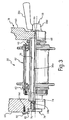
- the lower end of the outer tube 60 of the (first) fork leg 54 includes a first axle mounting opening or bore 66 that is unthreaded and a cutout 68 that receives one end of the hollow hub axle 36.
- the lower end of the outer tube 64 of the (second) fork leg 56 includes a second axle mounting opening or bore 70 with an internal thread 72 and a cutout 74 that receives one end of the hollow hub axle 36.
- the axle mounting bore 70 is configured and arranged to receive a wheel securing adapter 76 in a releasable and reinstallable manner. In other words, the wheel securing adapter 76 can be installed, removed and reinstalled without damaging the lower end of the outer tube 64 of the fork leg 56.
- the wheel securing adapter 76 is a one-piece, unitary member that is formed of a hard rigid material.
- the material of the wheel securing adapter 76 is harder than the material of the outer tube 64 of the fork leg 56.
- the wheel securing adapter 76 includes a first adapter portion 76a and a second adapter portion 76b with an internally threaded bore 76c extending completely through both the first and second adapter portions 76a and 76b.
- first and second adapter portions 76a and 76b are arranged to form a first end face on the first adapter portion 76a with a first opening and a second end face on the second adapter portion 76b with a second opening in which the internally threaded bore 76c extending axially from the first end face into the first adapter portion 76a to the second end face into the second adapter portion 76b.
- the internally threaded bore 76c could be a blind bore that only extends from the second end face on the second adapter portion 76b to the interface between the first and second adapter portions 76a and 76b.
- the internally threaded bore 76c threadedly engages the external thread 38b of the end of the skewer 38a of the wheel securing axle 38 to secure the hollow hub axle 36 to the outer tube 64 of the fork leg 56.
- the external surface (e.g., the external thread 76e in this embodiment) is configured and arranged to cooperate with the axle mounting bore 70 to prevent relative axial movement and relative rotational movement of the wheel securing adapter 76 within the axle mounting bore 70.
- an axial reaction force is applied between the internal thread 72 of the axle mounting bore 70 and the external thread 76e of the wheel securing adapter 76. This axial reaction force between the internal thread 72 and the external thread 76e prevents the wheel securing adapter 76 from moving either axially or rotationally relative to the outer tube 64 of the fork leg 56.
- the outer tube 64 of the fork leg 56 has a threaded hole 56a for threadedly receiving a bolt 80 to secure a locking tab 82 thereto.
- the locking tab 82 partially overlaps the axle mounting bore 70 as viewed in an axial direction of the axle mounting bore 70, and contacts the first end face on the first adapter portion 76a.
- the locking tab 82 prevents the wheel securing adapter 76 from moving axially relative to the outer tube 64 of the fork leg 56.
- the locking tab 82 prevents the wheel securing adapter 76 from moving axially relative to the outer tube 64 of the fork leg 56, the locking tab 82 prevents the wheel securing adapter 76 from unthreading (rotating). Further, by rotating the bolt 80, a user can adjust the axial position of the locking tab 82, and thereby, the final rotational position of the adapter 76 can also be adjusted.
- the second adapter portion 76b is mounted into the axle mounting bore 70 of the front fork 16 so that the rotational position of the adapter 76 is adjustable.
- the first adapter portion 76a has cylindrical shaped with a first maximum width or diameter D1.
- the second adapter portion 76b extends axially from the first adapter portion 76a.
- the second adapter portion 76b has a second maximum width or diameter D2 that is smaller than the first maximum or diameter D1 of the first adapter portion 76a to form an axially facing abutment surface 76d therebetween.
- the external surface of the second adapter portion 76b includes an external thread 76e that threadedly engages the internal thread 72 of the axle mounting bore 70 formed in the outer tube 64 of the fork leg 56.
- an additional wheel securing adapter 76' is illustrated that includes a first adapter portion 76a' and a second adapter portion 76b' with an internally threaded bore 76c' extending completely therethrough.
- the additional wheel securing adapter 76' is identical to the wheel securing adapter 76, except that the internally threaded bore 76c' has a larger diameter than the through bore 76c.
- the wheel securing skewers having various diameters can be used as needed and/or desired without changing the diameter of the axle mounting bore 70 of the front fork 16.
- this arrangement allows for a single front fork to be used with different size hubs. For example, if weight savings is desired, then a user can use a hub with a wheel securing skewer having a smaller diameter. Alternatively, if a higher rigidity is desired in the hub, then a user can use a hub with a wheel securing skewer having a larger diameter. Furthermore, by rotating the adapter, the user can adjust the screw starting point of the wheel securing skewer into the adapter to a desired location.
- a user can adjust the final position of the wheel securing lever by rotating the adapter as he/she wants, e.g. such that the wheel securing lever does not accidentally move to the open position by contacting against a foreign object (such as rocks, immoderate undulation of ground, or the like) during a ride of a bicycle.
- a foreign object such as rocks, immoderate undulation of ground, or the like
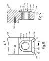
- the wheel securing adapter 176 is illustrated in accordance with a second embodiment of the present invention.
- the wheel securing adapter 176 is configured and arranged to be used with the front fork 16 illustrated in Figures 1 and 2 .
- the wheel securing adapter 176 is a one-piece, unitary member that is formed of a hard rigid material.
- the material of the wheel securing adapter 176 is harder than the material of the outer tube 64 of the fork leg 56.
- the wheel securing adapter 176 includes a first adapter portion 176a and a second adapter portion 176b with an internally threaded bore 176c extending completely through both the first and second adapter portions 176a and 176b.
- the wheel securing adapter 176 is identical to the wheel securing adapter 76, discussed above, except that the external surface of the first adapter portion 176a has plurality of circumferentially spaced apart notches or recesses 177.
- the recesses 177 selectively receive a locking tab 182 therein to prevent the wheel securing adapter 176 from unthreading.
- the locking tab 182 cooperates with one of the recesses 177 to prevent the wheel securing adapter 176 from moving axially or rotating relative to the outer tube 64 of the fork leg 56.
- the second adapter portion 176b is mounted into the axle mounting bore 70 of the front fork 16 so that the rotational position of the adapter 176 is adjustable. Furthermore, by rotating the wheel securing adapter 176, the user can adjust the screw starting point of the skewer 38a into the wheel securing adapter 176 to a desired location.
- the locking tab 182 also cooperates with one of the recesses 177 to lock the wheel securing adapter 176 in a position with a desired screw starting point for threading the skewer 38a into the wheel securing adapter 176. Since the remaining structures and/or arrangements are the same as the corresponding structures and/or arrangements of the prior embodiment, the wheel securing adapter 176 will not be discussed in further detail.
- an additional wheel securing adapter 176' is illustrated that includes a first adapter portion 176a' with recesses 177' and a second adapter portion 176b' with an internally threaded bore 176c' extending completely therethrough.
- the additional wheel securing adapter 176' is identical to the wheel securing adapter 176, except that the internally threaded bore 176c' has a larger diameter than the through bore 176c.
- a modified outer tube 264 is illustrated with the wheel securing adapter 176 installed therein.
- the modified outer tube 264 replaces the outer tube 64, and thus the remaining structure of the fork leg 56 is the same as discussed above.
- the only difference between the modified outer tube 264 and the outer tube 64 is that the shape of the lower end of the modified outer tube 264 has been changed to eliminate the notched in the lower end of the modified outer tube 264 and a different locking tab 282 is used. Since the remaining structures and/or arrangements are the same as the corresponding structures and/or arrangements of one of the prior embodiments, the outer tube 264 will not be discussed in further detail.
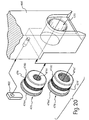
- a modified outer tube 364 with a wheel securing adapter 376 is illustrated in accordance with a third embodiment of the present invention.
- the modified outer tube 364 replaces the outer tube 64, and thus, the remaining structure of the fork leg 56 is the same as discussed above.
- the only difference between the modified outer tube 364 and the outer tube 64 is that the internal thread 72 of the axle mounting bore 70 has been changed to a plurality of axially extending splines 372 in an axle mounting bore 370.
- the wheel securing adapter 376 includes a first adapter portion 376a and a second adapter portion 376b with an internally threaded bore 376c extending completely through both the first and second adapter portions 376a and 376b.
- the wheel securing adapter 376 is identical to the wheel securing adapter 176, discussed above, except that the external surface of the second adapter portion 376b has a plurality of axially extending splines 379.
- the splines 379 of the wheel securing adapter 376 mate with the splines 372 of the axle mounting bore 370 of the modified outer tube 364.
- the second adapter portion 376b is mounted into the axle mounting bore 370 of the outer tube 364 so that the rotational position of the adapter 376 is adjustable. Since the remaining structures and/or arrangements are the same as the corresponding structures and/or arrangements of one of the prior embodiments, the outer tube 364 and the wheel securing adapter 376 will not be discussed in further detail.
- an additional wheel securing adapter 376' is illustrated that includes a first adapter portion 376a' with recesses 377' and a second adapter portion 376b' with an internally threaded bore 376c' extending completely therethrough and external splines 379'.
- the additional wheel securing adapter 376' is identical to the wheel securing adapter 376, except that the internally threaded bore 376c' has a larger diameter than the through bore 376c.
- a modified outer tube 464 with a wheel securing adapter 476 is illustrated in accordance with a fourth embodiment of the present invention.
- the modified outer tube 464 replaces the outer tube 64, and thus, the remaining structure of the fork leg 56 is the same as discussed above.
- the only difference between the modified outer tube 464 and the outer tube 64 is that the axle mounting bore 70 has been changed to a non-threaded axle mounting bore 470.
- the wheel securing adapter 476 includes a first adapter portion 476a and a second adapter portion 476b with an internally threaded bore 476c extending completely through both the first and second adapter portions 476a and 476b.
- the wheel securing adapter 476 is identical to the wheel securing adapter 76, discussed above, except that the dimensions have been changed and the external surface of the second adapter portion 476b has a plurality of axially extending serrations 479.
- the serrations 479 of the wheel securing adapter 476 create a secure press fit connection with the axle mounting bore 470 of the modified outer tube 464.
- the serrations 479 are formed in a middle section of the external surface of the second adapter portion 476b with the serrations 479 being axially spaced from first and second axial ends of the second adapter portion 476b by cylindrical portions that are free of the serrations.
- a plurality of axially extending splines can be formed to the bore 470 so as to releasably mate with the serrations 479 of the adapter 476.
- the second adapter portion of the adapter 476 is mounted into an axle mounting bore 470 of the modified outer tube 464 so that the rotational position of the adapter 476 is adjustable.
- a locking tab 482 can be attached to the modified outer tube 464 by the screw 80 to securely retain the adapter 476 to the modified outer tube 464. Since the remaining structures and/or arrangements are the same as the corresponding structures and/or arrangements of one of the prior embodiments, the outer tube 464 and the wheel securing adapter 476 will not be discussed in further detail.
- an additional wheel securing adapter 476' is illustrated that includes a first adapter portion 476a' and a second adapter portion 476b' with an internally threaded bore 476c' extending completely therethrough and external serrations 479'.
- the additional wheel securing adapter 476' is identical to the wheel securing adapter 476, except that the internally threaded bore 476c' has a larger diameter than the through bore 476c.
Claims (8)
- Laufrad-Befestigungsadapter (76) für Fahrräder, aufweisend:einen ersten Abschnitt (76a), der eine erste maximale Breite (D1) aufweist; undeinen zweiten Abschnitt (76b), der sich axial vom ersten Abschnitt (76a) erstreckt, wobei der zweite Abschnitt (76b) eine zweite maximale Breite (D2) aufweist, die geringer ist als die erste maximale Breite (D1) des ersten Abschnittes (76a), um eine in axialer Richtung weisende Widerlagerfläche (76d) zwischen diesen zu bilden, wobei der zweite Abschnitt (76b) konfiguriert und angeordnet ist, um in einer Achsenmontieröffnung (70) einer Fahrradvordergabel (16) montiert zu werden, so dass eine Drehposition des Adapters (76) einstellbar ist, wobei die Achsenmontieröffnung eine Montierbohrung (70) ist;wobei die ersten und zweiten Abschnitte (76a, 76b) angeordnet sind, um eine erste Stirnfläche am ersten Abschnitt (76a) und eine zweite Stirnfläche am zweiten Abschnitt (76b) zu bilden,wobei sich eine Gewindebohrung (76c) axial von der zweiten Stirnfläche in den zweiten Abschnitt erstreckt,dadurch gekennzeichnet, dass eine Außenfläche des zweiten Abschnittes (76b) konfiguriert und angeordnet ist, um mit der Achsenmontierbohrung (70) zusammenzuarbeiten, um zumindest eine Relativdrehbewegung des Laufrad-Befestigungsadapters (76) in der Achsenmontierbohrung (70) zu verhindern.
- Laufrad-Befestigungsadapter für Fahrräder nach Anspruch 1, wobei die Gewindebohrung (76c) eine Durchgangsbohrung ist, die eine erste Öffnung in der ersten Stirnfläche am ersten Abschnitt (76a) aufweist.
- Laufrad-Befestigungsadapter für Fahrräder nach Anspruch 1, wobei die Außenfläche des zweiten Abschnittes (76) ein Außengewinde (76e) ist.
- Laufrad-Befestigungsadapter für Fahrräder nach Anspruch 1, wobei der erste Abschnitt (76a) eine Außenfläche mit einer Mehrzahl von Vertiefungen aufweist.
- Laufrad-Befestigungsadapter für Fahrräder nach Anspruch 1, wobei die Außenfläche des zweiten Abschnittes (76) in axialer Richtung verlaufende Keilprofile aufweist.
- Laufrad-Befestigungsadapter für Fahrräder nach Anspruch 1, wobei die Außenfläche des zweiten Abschnittes (76) eine Mehrzahl von Verzahnungen aufweist, die in einem Mittelabschnitt der Außenfläche ausgebildet sind, wobei die Verzahnungen in axialer Richtung beabstandet von ersten und zweiten axialen Enden des zweiten Abschnittes (76b) angeordnet sind, und zwar durch zylindrische Abschnitte, die frei von Verzahnungen sind.
- Vordergabel (16) für Fahrräder, aufweisend:einen Gabelschaft (50);einen ersten Gabelschenkel (54), der ein erstes oberes Ende, das mit dem Gabelschaft (50) verbunden ist, und ein erstes untere Ende mit einer ersten Achsenbefestigungsöffnung (66) beinhaltet;einen zweiten Gabelschenkel (56), der ein zweites oberes Ende, das mit dem Gabelschaft (50) verbunden ist, und ein zweites unteres Ende mit einer zweiten Achsenmontieröffnung (70) beinhaltet; undeinen Laufrad-Befestigungsadapter (76) nach einem der Ansprüche 1 bis 6, der in der zweiten Achsenmontieröffnung (70) angeordnet ist.
- Fahrrad (10), aufweisend:eine Rahmeneinheit, die einen Hauptrahmen (12) beinhaltet;eine Vordergabel (16), die mit dem Hauptrahmen (12) drehbar verbunden ist, wobei die Vordergabel (16) einen Gabelschaft (50) mit einem Paar von Gabelschenkeln (54, 56) beinhaltet, die mit dem Gabelschaft (50) verbunden sind;ein Hinterrad (20) eines Fahrrades, das eine hintere Nabe mit einer Hinterachse beinhaltet, die mit dem Hauptrahmen verbunden ist; undein Vorderrad (18) eines Fahrrades, das eine vordere Nabe (30) mit einer Vorderrad-Befestigungsachse (38) beinhaltet, die mit der Vordergabel (16) verbunden ist,wobei die Vordergabel (16) einen Laufrad-Befestigungsadapter (76) nach einem der Ansprüche 1 bis 6 beinhaltet, wobei der Laufrad-Befestigungsadapter (76) in einer Achsenmontieröffnung (70) eines der Gabelschenkel (54, 56) montiert ist.
Applications Claiming Priority (1)
| Application Number | Priority Date | Filing Date | Title |
|---|---|---|---|
| US11/676,052 US7669871B2 (en) | 2007-02-16 | 2007-02-16 | Bicycle wheel securing adapter and bicycle fork using the same |
Publications (3)
| Publication Number | Publication Date |
|---|---|
| EP1958864A2 EP1958864A2 (de) | 2008-08-20 |
| EP1958864A3 EP1958864A3 (de) | 2009-03-04 |
| EP1958864B1 true EP1958864B1 (de) | 2010-12-15 |
Family
ID=39485158
Family Applications (1)
| Application Number | Title | Priority Date | Filing Date |
|---|---|---|---|
| EP07118172A Active EP1958864B1 (de) | 2007-02-16 | 2007-10-10 | Fahrrad-Schnellspanner |
Country Status (5)
| Country | Link |
|---|---|
| US (1) | US7669871B2 (de) |
| EP (1) | EP1958864B1 (de) |
| CN (2) | CN101244743B (de) |
| DE (1) | DE602007011194D1 (de) |
| TW (1) | TWI325394B (de) |
Cited By (1)
| Publication number | Priority date | Publication date | Assignee | Title |
|---|---|---|---|---|
| US8820854B2 (en) | 2011-08-03 | 2014-09-02 | Trek Bicycle Corporation | Bicycle wheel quick release assembly with clockable handle |
Families Citing this family (36)
| Publication number | Priority date | Publication date | Assignee | Title |
|---|---|---|---|---|
| US7503213B2 (en) * | 2006-04-27 | 2009-03-17 | American Axle & Manufacturing, Inc. | Bimetallic sensor mount for axles |
| US7654548B2 (en) * | 2007-02-16 | 2010-02-02 | Shimano Inc. | Bicycle wheel securing structure |
| US7669871B2 (en) * | 2007-02-16 | 2010-03-02 | Shimano Inc. | Bicycle wheel securing adapter and bicycle fork using the same |
| US7654546B2 (en) * | 2007-02-16 | 2010-02-02 | Shimano Inc. | Bicycle wheel securing structure |
| DE202007006451U1 (de) * | 2007-05-05 | 2007-10-25 | Grätz, Michael | Steckachssystem zur Radbefestigung |
| US8042881B2 (en) | 2007-05-16 | 2011-10-25 | Shimano Inc. | Bicycle wheel securing structure |
| US7909412B2 (en) * | 2007-07-02 | 2011-03-22 | Ashman J Leonard | Cycle wheel mounting system |
| EP2123549B1 (de) | 2008-05-21 | 2014-04-02 | Fox Factory, Inc. | Verfahren und Vorrichtung zum lösbaren Halten einer Fahrzeugradanordnung |
| DE102008029136A1 (de) * | 2008-06-19 | 2009-12-24 | Gustav Magenwirth Gmbh & Co. Kg | Fahrradachsenanordnung |
| US9815329B2 (en) * | 2009-01-02 | 2017-11-14 | Raphael Schlanger | Vehicle wheel axle assembly |
| US9446626B2 (en) * | 2009-12-30 | 2016-09-20 | Raphael Schlanger | Vehicle wheel hub assembly |
| US10112439B2 (en) * | 2009-12-30 | 2018-10-30 | Raphael Schlanger | Vehicle wheel axle assembly |
| DE202009000904U1 (de) * | 2009-01-23 | 2010-06-17 | Rose Versand Gmbh | Fahrrad-Steckachsensystem |
| US8113594B2 (en) | 2009-08-31 | 2012-02-14 | Hayes Bicycle Group Inc. | Apparatus for twist-to-lock retention of a wheel |
| US9045192B2 (en) * | 2010-05-14 | 2015-06-02 | Raphael Schlanger | Quick release hub assembly |
| US8075010B2 (en) | 2010-05-14 | 2011-12-13 | Specialized Bicycle Components, Inc. | Rear axle system for bicycle |
| TW201336700A (zh) | 2012-03-05 | 2013-09-16 | Shimano Kk | 自行車的輪轂軸用轉接配件 |
| CH706591A2 (de) * | 2012-06-04 | 2013-12-13 | Patrik Voegtli | Achseinrichtung für Fahrräder. |
| DE202013102691U1 (de) | 2013-06-21 | 2013-07-01 | Shimano Inc. | Fahrradradsicherungsachse und Fahrradradsicherungsanordnung |
| JP2015071406A (ja) * | 2013-09-09 | 2015-04-16 | 株式会社シマノ | 自転車用車輪固定機構 |
| US9376160B2 (en) * | 2013-11-01 | 2016-06-28 | Hayes Bicycle Group, Inc. | Axle assembly |
| US9308961B2 (en) * | 2013-11-27 | 2016-04-12 | Specialized Bicycle Components, Inc. | Bicycle frame with convertible dropouts |
| DE202013009812U1 (de) * | 2013-11-29 | 2014-02-18 | Derby Cycle Werke Gmbh | Steckbare Achseneinrichtung für ein Laufrad, insbesondere für ein Laufrad eines Fahrrades |
| US9228613B2 (en) * | 2014-02-24 | 2016-01-05 | Shimano Inc. | Bicycle bottom bracket assembly |
| NL2012339A (nl) * | 2014-02-28 | 2015-10-14 | Dti Advanced Tech B V | Achterwielas, alsmede achterwiel en rijwielframe voor een rijwiel |
| US9493034B1 (en) * | 2015-06-09 | 2016-11-15 | Shimano Inc. | Wheel securing assembly and bicycle wheel assembly |
| US9889903B2 (en) * | 2015-07-13 | 2018-02-13 | Misty Michelle McNeeley | Lower fork extender adapter |
| US10621499B1 (en) | 2015-08-03 | 2020-04-14 | Marca Research & Development International, Llc | Systems and methods for semantic understanding of digital information |
| US10073890B1 (en) | 2015-08-03 | 2018-09-11 | Marca Research & Development International, Llc | Systems and methods for patent reference comparison in a combined semantical-probabilistic algorithm |
| US10202165B2 (en) * | 2015-08-06 | 2019-02-12 | Shimano Inc. | Bicycle wheel-securing axle |
| US10540439B2 (en) | 2016-04-15 | 2020-01-21 | Marca Research & Development International, Llc | Systems and methods for identifying evidentiary information |
| US10850561B2 (en) * | 2016-07-26 | 2020-12-01 | Shimano Inc. | Bicycle wheel securing device |
| JP6846298B2 (ja) * | 2017-06-20 | 2021-03-24 | 株式会社シマノ | 自転車用ハブユニット |
| CN107218293B (zh) * | 2017-07-17 | 2023-12-26 | 江苏创斯达科技有限公司 | 一种轴连接结构 |
| US10780736B2 (en) * | 2017-11-17 | 2020-09-22 | Trek Bicycle Corporation | Dropout assembly |
| EP3831703B1 (de) * | 2018-02-28 | 2023-01-25 | SRAM Deutschland GmbH | Hinterrad-ritzelanordnung mit zwei einstückigen zur gemeinsamen drehung miteinander verbundenen teilanordnungen |
Family Cites Families (16)
| Publication number | Priority date | Publication date | Assignee | Title |
|---|---|---|---|---|
| FR893959A (fr) | 1943-02-01 | 1944-12-11 | Perfectionnements aux écrous de serrage pour cycles | |
| FR983137A (fr) | 1946-10-21 | 1951-06-19 | Dispositif de montage rapide des extrémités des fourches sur les exes des roues de bicyclettes, spécialement de course, ce dispositif permettant aussi de démonter ces mêmes fourches rapidement | |
| US5673925A (en) * | 1994-01-21 | 1997-10-07 | Stewart; Christopher R. | Quick release skewer system |
| US6089675A (en) * | 1997-08-19 | 2000-07-18 | Schlanger; Raphael | Quick release bicycle hub assembly |
| IT1296196B1 (it) * | 1997-11-21 | 1999-06-11 | Campagnolo Srl | Dispositivo per sopportare in rotazione un mozzo di ruota di bicicletta. |
| GB2345893B (en) | 1999-01-25 | 2001-03-14 | Atb Sales Ltd | Axle mounting assembly |
| US6409281B1 (en) * | 2000-12-04 | 2002-06-25 | Shimano Inc. | Bicycle hub with spacer and detachable freewheel |
| US6497314B2 (en) * | 2000-12-07 | 2002-12-24 | Shimano Inc. | Bicycle hub with sliding engagement member and detachable freewheel |
| US6572199B1 (en) * | 2002-04-03 | 2003-06-03 | General Motors Corporation | Flanged tubular axle shaft assembly |
| US7503239B2 (en) * | 2003-01-30 | 2009-03-17 | Shimano Inc. | Bicycle crank arm assembly |
| US6886894B2 (en) * | 2003-02-27 | 2005-05-03 | Shimano, Inc. | Bicycle hub axle |
| US7503213B2 (en) * | 2006-04-27 | 2009-03-17 | American Axle & Manufacturing, Inc. | Bimetallic sensor mount for axles |
| US7669871B2 (en) * | 2007-02-16 | 2010-03-02 | Shimano Inc. | Bicycle wheel securing adapter and bicycle fork using the same |
| US7530645B2 (en) * | 2007-03-01 | 2009-05-12 | Shimano Inc. | Bicycle wheel securing structure |
| US20080284127A1 (en) * | 2007-05-18 | 2008-11-20 | Shimano Inc. | Bicycle wheel securing structure |
| US7562943B2 (en) * | 2007-11-02 | 2009-07-21 | Shimano Inc. | Bicycle component securing structure |
-
2007
- 2007-02-16 US US11/676,052 patent/US7669871B2/en active Active
- 2007-08-17 TW TW096130524A patent/TWI325394B/zh active
- 2007-10-10 EP EP07118172A patent/EP1958864B1/de active Active
- 2007-10-10 DE DE602007011194T patent/DE602007011194D1/de active Active
-
2008
- 2008-02-18 CN CN2008100807443A patent/CN101244743B/zh active Active
- 2008-02-18 CN CN2008100807481A patent/CN101244744B/zh active Active
Cited By (1)
| Publication number | Priority date | Publication date | Assignee | Title |
|---|---|---|---|---|
| US8820854B2 (en) | 2011-08-03 | 2014-09-02 | Trek Bicycle Corporation | Bicycle wheel quick release assembly with clockable handle |
Also Published As
| Publication number | Publication date |
|---|---|
| TW200835623A (en) | 2008-09-01 |
| CN101244744A (zh) | 2008-08-20 |
| DE602007011194D1 (de) | 2011-01-27 |
| CN101244744B (zh) | 2011-04-06 |
| CN101244743A (zh) | 2008-08-20 |
| EP1958864A3 (de) | 2009-03-04 |
| US7669871B2 (en) | 2010-03-02 |
| EP1958864A2 (de) | 2008-08-20 |
| US20080197600A1 (en) | 2008-08-21 |
| CN101244743B (zh) | 2011-09-07 |
| TWI325394B (en) | 2010-06-01 |
Similar Documents
| Publication | Publication Date | Title |
|---|---|---|
| EP1958864B1 (de) | Fahrrad-Schnellspanner | |
| US8042881B2 (en) | Bicycle wheel securing structure | |
| EP1977965B1 (de) | Fahrradschnellspanner | |
| US7654548B2 (en) | Bicycle wheel securing structure | |
| US7562943B2 (en) | Bicycle component securing structure | |
| US7650817B2 (en) | Bicycle crank assembly | |
| US7556321B2 (en) | Bicycle wheel securing structure | |
| EP1213158B1 (de) | Fahrradnabe | |
| US7648211B2 (en) | Bicycle wheel securing structure | |
| EP1964767B1 (de) | Schnellspanner für die Befestigung eines Fahrradrades | |
| EP1961650B1 (de) | Fahrradsicherungsstruktur | |
| US20040254038A1 (en) | Bicycle rear derailleur guard | |
| US20060117905A1 (en) | Bicycle crank fixing structure | |
| US20060112780A1 (en) | Bicycle crank axle bearing assembly | |
| CN101307793A (zh) | 自行车轮固装结构 | |
| EP1659056B1 (de) | Fahrradkurbeleinheit | |
| US8231135B2 (en) | Device for adjusting the trail of a cycle front wheel assembly, a wheel equipped with such device, and a method of using same | |
| EP1683715B1 (de) | Befestigungsanordnung für Fahrradsattelträger |
Legal Events
| Date | Code | Title | Description |
|---|---|---|---|
| PUAI | Public reference made under article 153(3) epc to a published international application that has entered the european phase |
Free format text: ORIGINAL CODE: 0009012 |
|
| AK | Designated contracting states |
Kind code of ref document: A2 Designated state(s): AT BE BG CH CY CZ DE DK EE ES FI FR GB GR HU IE IS IT LI LT LU LV MC MT NL PL PT RO SE SI SK TR |
|
| AX | Request for extension of the european patent |
Extension state: AL BA HR MK RS |
|
| PUAL | Search report despatched |
Free format text: ORIGINAL CODE: 0009013 |
|
| AK | Designated contracting states |
Kind code of ref document: A3 Designated state(s): AT BE BG CH CY CZ DE DK EE ES FI FR GB GR HU IE IS IT LI LT LU LV MC MT NL PL PT RO SE SI SK TR |
|
| AX | Request for extension of the european patent |
Extension state: AL BA HR MK RS |
|
| 17P | Request for examination filed |
Effective date: 20090826 |
|
| AKX | Designation fees paid |
Designated state(s): DE FR IT |
|
| GRAP | Despatch of communication of intention to grant a patent |
Free format text: ORIGINAL CODE: EPIDOSNIGR1 |
|
| GRAS | Grant fee paid |
Free format text: ORIGINAL CODE: EPIDOSNIGR3 |
|
| GRAA | (expected) grant |
Free format text: ORIGINAL CODE: 0009210 |
|
| AK | Designated contracting states |
Kind code of ref document: B1 Designated state(s): DE FR IT |
|
| REF | Corresponds to: |
Ref document number: 602007011194 Country of ref document: DE Date of ref document: 20110127 Kind code of ref document: P |
|
| PLBE | No opposition filed within time limit |
Free format text: ORIGINAL CODE: 0009261 |
|
| STAA | Information on the status of an ep patent application or granted ep patent |
Free format text: STATUS: NO OPPOSITION FILED WITHIN TIME LIMIT |
|
| 26N | No opposition filed |
Effective date: 20110916 |
|
| REG | Reference to a national code |
Ref country code: DE Ref legal event code: R097 Ref document number: 602007011194 Country of ref document: DE Effective date: 20110916 |
|
| PGFP | Annual fee paid to national office [announced via postgrant information from national office to epo] |
Ref country code: FR Payment date: 20141008 Year of fee payment: 8 |
|
| REG | Reference to a national code |
Ref country code: FR Ref legal event code: ST Effective date: 20160630 |
|
| PG25 | Lapsed in a contracting state [announced via postgrant information from national office to epo] |
Ref country code: FR Free format text: LAPSE BECAUSE OF NON-PAYMENT OF DUE FEES Effective date: 20151102 |
|
| PGFP | Annual fee paid to national office [announced via postgrant information from national office to epo] |
Ref country code: IT Payment date: 20161024 Year of fee payment: 10 |
|
| PG25 | Lapsed in a contracting state [announced via postgrant information from national office to epo] |
Ref country code: IT Free format text: LAPSE BECAUSE OF NON-PAYMENT OF DUE FEES Effective date: 20171010 |
|
| P01 | Opt-out of the competence of the unified patent court (upc) registered |
Effective date: 20230428 |
|
| PGFP | Annual fee paid to national office [announced via postgrant information from national office to epo] |
Ref country code: DE Payment date: 20230830 Year of fee payment: 17 |