EP1958727A1 - Method and device for machining workpieces with high-energy beams - Google Patents
Method and device for machining workpieces with high-energy beams Download PDFInfo
- Publication number
- EP1958727A1 EP1958727A1 EP08100166A EP08100166A EP1958727A1 EP 1958727 A1 EP1958727 A1 EP 1958727A1 EP 08100166 A EP08100166 A EP 08100166A EP 08100166 A EP08100166 A EP 08100166A EP 1958727 A1 EP1958727 A1 EP 1958727A1
- Authority
- EP
- European Patent Office
- Prior art keywords
- rotation
- workpiece
- axis
- radiation
- melt
- Prior art date
- Legal status (The legal status is an assumption and is not a legal conclusion. Google has not performed a legal analysis and makes no representation as to the accuracy of the status listed.)
- Withdrawn
Links
Images
Classifications
-
- B—PERFORMING OPERATIONS; TRANSPORTING
- B23—MACHINE TOOLS; METAL-WORKING NOT OTHERWISE PROVIDED FOR
- B23K—SOLDERING OR UNSOLDERING; WELDING; CLADDING OR PLATING BY SOLDERING OR WELDING; CUTTING BY APPLYING HEAT LOCALLY, e.g. FLAME CUTTING; WORKING BY LASER BEAM
- B23K26/00—Working by laser beam, e.g. welding, cutting or boring
- B23K26/08—Devices involving relative movement between laser beam and workpiece
- B23K26/0823—Devices involving rotation of the workpiece
-
- B—PERFORMING OPERATIONS; TRANSPORTING
- B23—MACHINE TOOLS; METAL-WORKING NOT OTHERWISE PROVIDED FOR
- B23K—SOLDERING OR UNSOLDERING; WELDING; CLADDING OR PLATING BY SOLDERING OR WELDING; CUTTING BY APPLYING HEAT LOCALLY, e.g. FLAME CUTTING; WORKING BY LASER BEAM
- B23K15/00—Electron-beam welding or cutting
- B23K15/002—Devices involving relative movement between electronbeam and workpiece
-
- B—PERFORMING OPERATIONS; TRANSPORTING
- B23—MACHINE TOOLS; METAL-WORKING NOT OTHERWISE PROVIDED FOR
- B23K—SOLDERING OR UNSOLDERING; WELDING; CLADDING OR PLATING BY SOLDERING OR WELDING; CUTTING BY APPLYING HEAT LOCALLY, e.g. FLAME CUTTING; WORKING BY LASER BEAM
- B23K26/00—Working by laser beam, e.g. welding, cutting or boring
- B23K26/16—Removal of by-products, e.g. particles or vapours produced during treatment of a workpiece
Landscapes
- Engineering & Computer Science (AREA)
- Physics & Mathematics (AREA)
- Optics & Photonics (AREA)
- Mechanical Engineering (AREA)
- Plasma & Fusion (AREA)
- Laser Beam Processing (AREA)
Abstract
Description
Die Erfindung betrifft ein Verfahren zum Bearbeiten von Werkstücken gemäß dem Oberbegriff des Anspruchs 1 sowie eine Vorrichtung zur Durchführung des Verfahrens gemäß dem Oberbegriff des Anspruchs 8.The invention relates to a method for processing workpieces according to the preamble of claim 1 and to an apparatus for carrying out the method according to the preamble of claim 8.
Bei der Materialbearbeitung mittels energiereicher Strahlung, wie beispielsweise Laserstrahlung, wird die Strahlung auf das zu bearbeitende Material fokussiert. Die Absorption der Strahlung führt zum Aufheizen, Aufschmelzen und/oder zum Verdampfen des Materials. Mit Hilfe dieses Bearbeitungsprinzips sind verschiedene Bearbeitungsverfahren, wie beispielsweise das Laserabtragen oder das Laserschneiden möglich.In the processing of materials by means of high-energy radiation, such as laser radiation, the radiation is focused on the material to be processed. The absorption of the radiation leads to heating, melting and / or evaporation of the material. With the aid of this processing principle, various processing methods, such as laser ablation or laser cutting, are possible.
Beim Laserabtragen wird durch den entstehenden Überdruck das Material an der Wechselwirkungszone entfernt. Um das Material bis zur Verdampfung zu erhitzen, sind für den Prozess hohe Strahlungsintensitäten von mehr als 106 W/mm2 erforderlich. Je nach Wahl der Parameter, wie Pulsleistung und Pulsdauer der Strahlung und auch in Abhängigkeit des Materials des Werkstücks (beispielsweise Dichte und Schmelzviskosität) verbleiben jedoch Schmelzereste in der Wechselwirkungszone (Aufschmelzbereich), die nach der Erstarrung zu unerwünschten Graten und Unregelmäßigkeiten in der Oberfläche führen. Zur Austreibung der Schmelze aus dem Aufschmelzbereich werden daher Arbeitsgase eingesetzt, die die unerwünschte Restschmelze aus der Aufschmelzzone fördern, das heißt austreiben sollen. Je nach Tiefe der erzeugten Bohrung oder Nut und je nach geforderter Bearbeitungsqualität stellt die Schmelzeaustreibung ein mehr oder weniger großes Problem dar.During laser ablation, the resulting overpressure removes the material at the interaction zone. In order to heat the material until it evaporates, the process requires high radiation intensities of more than 10 6 W / mm 2 . Depending on the choice of parameters, such as pulse power and pulse duration of the radiation and also depending on the material of the workpiece (for example density and melt viscosity), however, melt residues remain in the interaction zone (melting range), which leads to undesired burrs and irregularities in the surface after solidification. For expulsion of the melt from the melting range therefore working gases are used, which are the undesirable residual melt from the melting zone promote, that is, drive out. Depending on the depth of the bore or groove produced and depending on the required machining quality, the melt expulsion represents a more or less serious problem.
Das Laserschneiden ist ein thermisches Trennverfahren und eignet sich zum Trennen von metallischen und nicht-metallischen Werkstoffen. Dabei wird zwischen drei Schneidverfahren unterschieden. Beim sogenannten Schmelzschneiden wird das zu schneidende Werkstück in der Schnittzone mittels eines Lasers zum Schmelzen gebracht und mit Hilfe eines Austreibungsgases unter hohem Druck ausgeblasen. Beim sogenannten Brennschneiden wird als Austreibungsgas Sauerstoff eingesetzt, mittels dem aufgrund eines resultierenden Oxidationsprozesses große Eindringtiefen des Schnittes in das Werkstück erreicht werden können. Durch die Oxidationsvorgang beim Laserbrennschneiden entstehen an der Schnittkante des Werkstoffes Oxidreste, welche bei der weiteren Verarbeitung zu Problemen führen. Beim sogenannten Sublimierschneiden wird der Werkstoff nicht aufgeschmolzen, sondern verdampft. Hierzu sind jedoch hohe Anforderungen an die Strahlungsquelle, wie hohe Repetitionsraten oder ultrakurze Impulse notwendig, um eine vollständige Verdampfung in der Schneidzone zu erreichen.Laser cutting is a thermal separation process and is suitable for separating metallic and non-metallic materials. There is a distinction between three cutting methods. In so-called fusion cutting, the workpiece to be cut is melted in the cutting zone by means of a laser and blown out under high pressure with the help of an expulsion gas. In so-called flame cutting, oxygen is used as the expulsion gas, by means of which, due to a resulting oxidation process, large penetration depths of the cut into the workpiece can be achieved. The oxidation process during laser flame cutting produces oxide residues at the cutting edge of the material, which lead to problems during further processing. In the so-called sublimation cutting the material is not melted, but evaporated. However, high demands on the radiation source, such as high repetition rates or ultrashort pulses, are necessary in order to achieve complete vaporization in the cutting zone.
Aus der
Bei den beschriebenen Bearbeitungsverfahren sind große Abtragungsvolumina bzw. groß zu schneidende Materialdecken mit hohen Prozessdauern verbunden, so dass die bekannten Bearbeitungsverfahren für diese Zwecke nicht wirtschaftlich einsetzbar sind.From the
In the processing methods described, large removal volumes or material slabs that are to be cut to a large extent are associated with high process times, so that the known processing methods can not be used economically for these purposes.
Der Erfindung liegt die Aufgabe zugrunde, ein Bearbeitungsverfahren sowie eine Vorrichtung zur Durchführung des Verfahrens anzugeben, bei denen die beim Bearbeitungsprozess entstehende Schmelze auf einfache Weise, vorzugsweise mindestens nahezu rückstandsfrei, aus dem Aufschmelzbereich austreibbar ist.The invention has for its object to provide a processing method and an apparatus for performing the method in which the resulting melt during the machining process in a simple manner, preferably at least almost residue-free, can be driven out of the melting area.
Hinsichtlich des Verfahrens wird diese Aufgabe mit den Merkmalen des Anspruchs 1 und hinsichtlich der Vorrichtung mit den Merkmalen des Anspruchs 8 gelöst. Vorteilhafte Weiterbildungen der Erfindung sind in den Unteransprüchen angegeben. In den Rahmen der Erfindung fallen auch sämtliche Kombinationen aus zumindest zwei von in der Beschreibung, den Ansprüchen und/oder den Figuren angegebenen Merkmalen.With regard to the method, this object is achieved with the features of claim 1 and with regard to the device with the features of claim 8. Advantageous developments of the invention are specified in the subclaims. All combinations of at least two features specified in the description, the claims and / or the figures also fall within the scope of the invention.
Der Erfindung liegt der Gedanke zugrunde, das Werkstück rotierend anzuordnen, wobei die Rotationsgeschwindigkeit so zu wählen ist, dass die auf die im Aufschmelzbereich durch die Strahlungsbeaufschlagung entstehende Schmelze wirkenden Fließkräfte so groß sind, dass die Schmelze zumindest teilweise, bevorzugt zumindest näherungsweise vollständig aus dem Aufschmelzbereich ausgetrieben wird. Auf im Stand der Technik zwingend notwendige Austreibungsgase kann dabei, muss jedoch nicht, aufgrund der Erfindung verzichtet werden.The invention is based on the idea of arranging the workpiece in a rotating manner, wherein the rotational speed is such that the flow forces acting on the melt produced in the melting region by the application of radiation are so great that the melt is at least partially, preferably at least approximately completely, out of the melting region is expelled. In the prior art mandatory expulsion gases can, but need not, be waived due to the invention.
An die Geometrie des Werkstücks sind zur erfolgreichen Anwendung des erfindungsgemäßen Verfahrens keine besonderen Anforderungen zu stellen. Die Geometrie des Werkstücks muss es lediglich zulassen, dass durch die auftretenden Fliehkräfte ein Austreiben der Schmelze möglich ist. Das Werkstück kann dabei rotationssymmetrisch aber auch asymmetrisch zur Rotationsachse ausgebildet sein. Je nach Wahl der Rotationsgeschwindigkeit ist es ferner möglich, die Schmelze definiert zu verformen und somit komplexe Werkstückgeometrien herzustellen. Das erfindungsgemäße Verfahren und die erfindungsgemäße Vorrichtung eignen sich beispielsweise zur Bearbeitung bzw. Herstellung von Profilen, Nuten und Schnitten. Bei Bedarf können mehrere Strahlungsquellen, insbesondere Laserstrahlungsquellen und/oder Elektronenstrahlungsquellen gleichzeitig zur Bearbeitung eines rotierenden Werkstücks eingesetzt werden. Von Vorteil ist es, der mindestens einen Strahlungsquelle eine Optik zur Fokussierung des erzeugten Strahls im Aufschmelzbereich zuzuordnen, wobei bevorzugt die Optik derart ansteuerbar ist, dass der Fokus des erzeugten Strahls an die Bearbeitungssituation bzw. den Bearbeitungsstand (-grad) anpassbar ist.The geometry of the workpiece does not require any special requirements for the successful application of the method according to the invention. The geometry of the workpiece must only allow the centrifugal forces that occur to drive out the melt. The workpiece can be rotationally symmetrical but also asymmetrical to the axis of rotation. Depending on the choice of the rotational speed, it is also possible to deform the melt defined and thus produce complex workpiece geometries. The inventive method and the invention Device are suitable for example for the processing or production of profiles, grooves and cuts. If required, a plurality of radiation sources, in particular laser radiation sources and / or electron radiation sources, can be used simultaneously for processing a rotating workpiece. It is advantageous to associate with the at least one radiation source an optic for focusing the generated beam in the fusing region, the optic preferably being controllable in such a way that the focus of the generated beam can be adapted to the processing situation or the processing state (degree).
Ein weiterer Vorteil des erfindungsgemäßen Verfahrens und der erfindungsgemäßen Vorrichtung besteht darin, dass relativ geringe Anforderungen an die Strahlenquellentechnik bestehen. Es können beispielsweise konventionelle gepulste oder auch CW-Laser eingesetzt werden. Hohe Repetitionsraten oder ultrakurze Pulse müssen nicht realisiert werden, da es für das erfindungsgemäße Verfahren nicht notwendig ist, das der Werkstoff vollständig verdampft. Hieraus resultiert eine höhere Prozesseffizienz, da das Abtragen von flüssigem Material (Schmelze) weniger Energie erfordert als die Verdampfung des Werkstoffes. Beim Abtragen mit einer gepulsten Strahlungsquelle kann beispielsweise mit einem einzigen Puls eine vollständige Umfangsnut erzeugt werden. Das erfindungsgemäße Verfahren und die erfindungsgemäße Vorrichtung ermöglichen weiterhin die Ausbildung neuer Nutformen, die insbesondere abhängig von der verwendeten Strahlungsquelle und den eingestellten Parameters sind.Another advantage of the method and apparatus of the invention is that there are relatively low demands on the radiation source technology. For example, conventional pulsed or also CW lasers can be used. High repetition rates or ultrashort pulses need not be realized since it is not necessary for the process according to the invention that the material evaporates completely. This results in a higher process efficiency, since the removal of liquid material (melt) requires less energy than the evaporation of the material. When ablating with a pulsed radiation source, for example, with a single pulse, a complete circumferential groove can be generated. The method according to the invention and the device according to the invention furthermore make it possible to form new groove shapes, which in particular are dependent on the radiation source used and the set parameters.
In Weiterbildung der Erfindung ist mit Vorteil vorgesehen, dass die Schmelze durch Abschleudern von dem Werkstück, insbesondere in tangentialer Richtung relativ zu dem Werkstück aus dem Aufschmelzbereich ausgetrieben wird. Hierzu muss die Rotationsgeschwindigkeit zur Erzielung entsprechend großer Fliehkräfte entsprechend hoch gewählt werden. Bevorzugt ist dabei eine der Strahlungsquelle zugeordnete Optik derart, insbesondere schräg, anzuordnen, dass diese nicht von abgeschleuderten Schmelzeresten beschädigt werden kann.In a development of the invention, it is advantageously provided that the melt is driven out of the melting area by centrifuging the workpiece, in particular in the tangential direction relative to the workpiece. For this purpose, the rotational speed to achieve correspondingly large centrifugal forces must be selected correspondingly high. In this case, one of the radiation source associated optics is preferably such, in particular obliquely, to arrange that they can not be damaged by thrown off Schmelzeresten.
Von besonderem Vorteil ist es, wenn die Strahlungsquelle um eine zweite Rotationsachse rotierbar angeordnet ist, wobei bevorzugt die zweite Rotationsachse identisch mit der ersten Rotationsachse ist. Von Vorteil ist es dabei, wenn die Strahlungsquelle zumindest zeitweise mit derselben Rotationsgeschwindigkeit rotiert, wie das zu bearbeitende Werkstück, also hinsichtlich der Rotationsbewegung eine Relativbewegung zwischen dem Werkstück und der Strahlungsquelle unterbunden wird. Hierdurch ist es beispielsweise möglich, mittels der Strahlungsquelle (gerade) Bohrungen in das Werkstück einzubringen. Mit Vorteil wird die Strahlungsquelle zusammen mit dem Werkstück mittels einer Werkstückrotationseinrichtung um eine gemeinsame Drehachse rotiert. Alternativ dazu ist es denkbar, eine separate Rotationseinrichtung für die Strahlungsquelle vorzusehen. Aufgrund der i.d.R. großen Abmessung der Strahlungsquelle kann es für viele Anwendung von Vorteil sein, nicht die gesamte Strahlungsquelle, sondern lediglich den von der Strahlungsquelle erzeugten Bearbeitungsspot (Strahlungsfokus) rotierbar anzuordnen. Hierzu kann beispielsweise ein Scanner in Kombination mit einem Kegelspiegel eingesetzt werden.It is particularly advantageous if the radiation source is arranged rotatable about a second axis of rotation, wherein preferably the second axis of rotation is identical to the first axis of rotation. It is advantageous if the radiation source at least temporarily rotates at the same rotational speed, as the workpiece to be machined, ie with respect to the rotational movement, a relative movement between the workpiece and the radiation source is prevented. This makes it possible, for example, by means of the radiation source (straight) to introduce holes in the workpiece. Advantageously, the radiation source is rotated together with the workpiece by means of a workpiece rotation device about a common axis of rotation. Alternatively, it is conceivable to provide a separate rotation device for the radiation source. Due to the i.d.R. With a large dimension of the radiation source, it may be advantageous for many applications not to arrange the entire radiation source rotatably, but only the machining spot (radiation focus) generated by the radiation source. For this purpose, for example, a scanner can be used in combination with a cone mirror.
Alternativ oder bevorzugt zusätzlich zu einer rotierenden Anordnung der Strahlungsquelle ist die Strahlungsquelle, oder der Bearbeitungsspot, insbesondere mittels einer Verstelleinrichtung relativ zu dem Werkstück verstellbar. Zusätzlich oder alternativ kann auch das Werkstück relativ zur Strahlungsquelle bzw. zum Bearbeitungsspot verstellbar angeordnet sein. Bevorzugt ist die Verstelleinrichtung derart ausgebildet, dass eine Verstellung der (vorzugsweise rotierenden) Strahlungsquelle relativ zu dem Werkstück parallel zur Rotationsachse (X-Achse) möglich ist. Zusätzlich oder alternativ ist es von Vorteil die Strahlungsquelle relativ zu dem Werkstück in radialer Richtung, also entlang einer X-Achse zu bewegen. Zusätzlich ist es von Vorteil, wenn die Strahlungsquelle zusätzlich oder alternativ quer, das heißt entlang einer Y-Achse relativ zu der Rotationsachse des Werkstücks verstellbar ist. Bei einer rotierenden Anordnung der Strahlungsquelle kann durch eine Anpassung der Rotationsgeschwindigkeit der Strahlungsquelle (bei Verwendung einer separaten Rotationseinrichtung) eine relative Rotationsbewegung zwischen der Strahlungsquelle und dem Werkstück realisiert werden. Zusätzlich oder alternativ ist es denkbar, die Verstelleinrichtung derart auszubilden, dass die (insbesondere zusammen mit dem Werkstück rotierende) Strahlungsquelle auf einer (Teil-) Kreisbahn um das Werkstück verfahrbar ist. Weiter von Vorteil ist es, die Strahlungsquelle in radialer Richtung (Z-Achse) verstellbar anzuordnen. Durch die Realisierung mindestens einer Relativverstellbarkeit zwischen Strahlungsquelle und Werkstück ist es möglich, komplexe Nutgeometrien oder Schneidgeometrien zu realisieren. Es ist aufgrund der beschriebenen Ausgestaltung des Verfahrens und der Vorrichtung möglich, nicht nur lineare Konturen innerhalb einer Ebene zu realisieren, sondern es können auch spezielle Nutformen verwirklicht werden, wie beispielsweise Spiral- oder Sinusformen. Bevorzugt ist dabei eine Strahlungsoptik bzw. der Strahlungsfokus an die Abtragungsgeometrie zur Optimierung des Abtragungsergebnisses anpassbar. Das beschriebene Verfahren und die beschriebene Vorrichtung ermöglichen es zusätzlich beispielsweise Gewinde in das Werkstück einzuformen.Alternatively or preferably, in addition to a rotating arrangement of the radiation source, the radiation source, or the machining spot, in particular by means of an adjusting device relative to the workpiece adjustable. Additionally or alternatively, the workpiece may be arranged to be adjustable relative to the radiation source or the machining spot. Preferably, the adjusting device is designed such that an adjustment of the (preferably rotating) radiation source relative to the workpiece parallel to the axis of rotation (X-axis) is possible. Additionally or alternatively, it is advantageous to move the radiation source relative to the workpiece in the radial direction, ie along an X-axis. In addition, it is advantageous if the radiation source is additionally or alternatively transversely, that is adjustable along a Y-axis relative to the axis of rotation of the workpiece. In a rotating arrangement of the radiation source can be realized by adjusting the rotational speed of the radiation source (when using a separate rotation means) relative rotational movement between the radiation source and the workpiece. Additionally or alternatively, it is conceivable that the adjusting device in such a way that the (in particular rotating together with the workpiece) radiation source is movable on a (partial) circular path around the workpiece. Another advantage is to arrange the radiation source in the radial direction (Z-axis) adjustable. By realizing at least one relative adjustability between the radiation source and the workpiece, it is possible to realize complex groove geometries or cutting geometries. It is possible due to the described embodiment of the method and the device not only to realize linear contours within a plane, but also special groove shapes can be realized, such as spiral or sinusoidal shapes. Radiation optics or the radiation focus can be adapted to the ablation geometry in order to optimize the ablation result. The method described and the device described additionally make it possible, for example, to thread threads into the workpiece.
Zur Realisierung großer Abtragungsvolumina bzw. großer Schnitttiefen ist es von Vorteil, wenn ein Bearbeitungsvorgang mehrfach wiederholt wird, insbesondere mittels der Strahlungsquelle mehrfach dieselbe Bearbeitungsbahn (Relativbewegungsbahn) abgefahren wird. Bei einem derartigen, schichtweisen Materialabtrag kann auf einen im Stand der Technik beim Laserschneiden notwendigen, starke Rückreflexe und Materialspritzer verursachenden, Durchstoßvorgang mittels des energiereichen Strahls verzichtet werden. Hierdurch wird die Gefahr einer Beschädigung der Strahlungsoptik miniert. Aufgrund der schichtweisen Bearbeitung können ferner Strahlungsquellen mit niedriger Leistung eingesetzt werden, was zu einer Herabsetzung der thermischen Aufheizung des Materials an den Schnittkanten führt. Die hohe thermische Aufheizung bei herkömmlichen Verfahren erschwert die Weiterverarbeitung des geschnittenen Zwischen- und/oder Endproduktes. Da beim beschriebenen Verfahren der Aufheizvorgang zeitlich kürzer ist und auch nur geringe Tiefen im Material erreicht werden müssen, werden die im Stand der Technik auftretenden extrem hohen Temperaturengradienten während des Schneidvorgangs vermieden.For realizing large ablation volumes or large depths of cut, it is advantageous if a machining operation is repeated several times, in particular by means of the radiation source several times the same machining path (relative movement path) is traversed. In such a layered removal of material can be dispensed with a necessary in the art in laser cutting, strong back-reflection and splatter causing, piercing process by means of the high-energy beam. This minimizes the risk of damaging the radiation optics. Because of the layered processing, low power radiation sources may also be used, resulting in a reduction of the thermal heating of the material at the cut edges. The high thermal heating in conventional methods complicates the further processing of the cut intermediate and / or end product. Since the process described in the heating process is shorter in time and only small depths in the material must be achieved, the extremely high temperature gradients occurring in the prior art are avoided during the cutting process.
In Ausgestaltung der Erfindung ist mit Vorteil vorgesehen, dass zusätzlich zur schnellen rotierenden Anordnung des Werkstücks zur noch weiter verbesserten Austreibung, insbesondere Abschleuderung der Schmelze ein Austreibungsgas eingesetzt wird. Bei der Verwendung von Sauerstoff können dabei extrem große Eindringtiefen realisiert werden. Ferner können durch geeignete Austreibungsgase die Oberflächenspannung und/oder die Viskosität der Schmelze positiv beeinflusst werden.In an embodiment of the invention is advantageously provided that in addition to the fast rotating arrangement of the workpiece for even further expulsion, in particular Abschleuderung the melt an expulsion gas is used. When using oxygen, extremely large penetration depths can be achieved. Furthermore, the surface tension and / or the viscosity of the melt can be positively influenced by suitable expulsion gases.
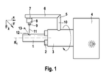
Weitere Vorteile, Merkmale und Einzelheiten der Erfindung ergeben sich aus der nachfolgenden Beschreibung eines bevorzugten Ausführungsbeispiels sowie anhand der Zeichnung. Diese zeigt in der einzigen Figur den schematischen Aufbau einer möglichen Vorrichtung zur Durchführung eines Bearbeitungsverfahrens von Werkstücken unter Einsatz von Laserstrahlung.Further advantages, features and details of the invention will become apparent from the following description of a preferred embodiment and from the drawing. This shows in the single figure the schematic structure of a possible device for carrying out a machining method of workpieces using laser radiation.
In dem beschriebenen Ausführungsbeispiel wird ein Werkstück 1 mit Hilfe von Laserstrahlung bearbeitet. Die Wahl von Laserstrahlung als energiereiche Strahlung ist lediglich beispielhaft und nicht einschränkend zu verstehen. Alternativ können andere energiereiche Strahlungen, wie beispielsweise Elektronenstrahlung, eingesetzt werden.In the described embodiment, a workpiece 1 is processed by means of laser radiation. The choice of laser radiation as high-energy radiation is merely illustrative and not restrictive. Alternatively, other high-energy radiation, such as electron radiation, can be used.
Das in dem gezeigten Ausführungsbeispiel als Vollmaterialzylinder ausgebildete, rotationssymmetrische Werkstück 1 ist mit Hilfe einer Fixiereinrichtung 2 (Spannfutter) an einer rotierbaren Welle 3 fixiert. Die Welle 3 wird dabei rotierend von einem geschwindigkeitsregelbaren Antriebsmotor um eine erste Rotationsachse R1 in Rotation versetzt.The rotationally symmetrical workpiece 1 designed as a solid material cylinder in the exemplary embodiment shown is fixed to a
An der rotierbaren Welle 3 ist ein L-förmiger Haltearm 5 drehfest fixiert, dessen in der Zeichnungsebene oberer Schenkel 6 sich parallel zur Rotationsachse R1 erstreckt. Relativ zu dem oberen Schenkel 6 ist eine als Verstellschlitten insbesondere Kreuzschlitten ausgebildete Verstelleinrichtung 7 verstellbar. Die Verstelleinrichtung 7 trägt eine als Laserstrahlungsquelle ausgebildete Strahlungsquelle 8 mit einer Fokussieroptik 9. Mittels der Verstelleinrichtung 7 ist die Strahlungsquelle 8 relativ zu dem Werkstück 1 entlang einer X-Achse (parallel zur Rotationsachse R1) sowie entlang einer Y-Achse (quer zur Rotationsachse R1) verstellbar. Die Verstelleinrichtung 7 ist derart ausgebildet, dass die Strahlungsquelle 8 auch entlang einer Z-Achse (in radialer Richtung relativ zu der Rotationsachse R1) verstellbar ist. Diese Verstellbarkeit kann auch dadurch realisiert werden, dass ein radial zur Rotationsachse R1 verlaufender zweiter Schenkel 10 des Haltearms 5 in radialer Richtung ausfahrbar ausgebildet ist.On the
Zusätzlich ist es denkbar, dass die Verstelleinrichtung 7 eine Verstellung der Strahlungsquelle 8 auf einer nicht gezeigten Teilkreisführung um die Rotationsachse R1 zulässt. Alternativ dazu ist es realisierbar, zur Rotation der Strahlungsquelle 8 um die Rotationsachse R1 des Werkstücks 1 oder um eine andere, bevorzugt zur Rotationsachse R1 parallele Achse eine nicht gezeigte separate Rotationseinrichtung vorzusehen.In addition, it is conceivable that the adjusting device 7 permits an adjustment of the radiation source 8 on a partial circuit guide (not shown) about the axis of rotation R 1 . Alternatively, it is feasible to provide for the rotation of the radiation source 8 about the rotation axis R 1 of the workpiece 1 or about another, preferably parallel to the axis of rotation R 1 axis, a separate rotation means, not shown.
Der von der Strahlungsquelle 8 erzeugte Laserstrahl 11 wird mittels der Fokussieroptik 9 auf das Werkstück 1, insbesondere auf einen Aufschmelzbereich 12 (Wechselwirkungsbereich) fokussiert, so dass Werkstückmaterial aufgeschmolzen wird. Durch eine entsprechend schnelle Rotation des Werkstücks 1 mittels des Antriebsmotors 4 um die Rotationsachse R1 wird dabei entstehende Schmelze 13 in etwa tangential relativ zu dem sich drehenden Werkstück 1 von dem Werkstück 1 nach außen abgeschleudert. Gegebenenfalls können zusätzlich die Austreibung der Schmelze 13 unterstützende Arbeitsgase in den Aufschmelzbereich 12 eingeblasen werden.The
Durch geeignete Verstellung der Strahlungsquelle 8 und gegebenenfalls Einstellung der Fokussieroptik 9 können (nahezu) beliebig komplexe Geometrien in das Werkstück 1 eingeformt werden, oder das Werkstück kann entlang komplexer Konturen geschnitten werden.By suitable adjustment of the radiation source 8 and optionally adjustment of the focusing optics 9, (almost) arbitrarily complex geometries can be formed in the workpiece 1, or the workpiece can be cut along complex contours.
Claims (10)
dadurch gekennzeichnet,
dass die Rotationsgeschwindigkeit so hoch gewählt wird, dass die Schmelze (13) durch die rotationsbedingt wirkende Fliehkraft zumindest teilweise aus dem Aufschmelzbereich (12) ausgetrieben wird.Method for processing workpieces with a high-energy radiation generated by a radiation source (8), in particular laser radiation (11) or electron radiation, wherein the workpiece (1) acted upon by the radiation rotates about a first axis of rotation (R 1 ) and due to the radiation in one Melting region (12) on the workpiece (1) a melt (13) is formed,
characterized,
that the rotational speed is selected to be so high that the melt (13) is expelled at least partially from the melting region (12) by the centrifugal force acting as a result of the rotation.
dadurch gekennzeichnet,
dass die Schmelze (13) in tangentialer Richtung relativ zu dem Werkstück (1) von dem Werkstück (1) abgeschleudert wird.Method according to claim 1,
characterized,
in that the melt (13) is thrown off the workpiece (1) in the tangential direction relative to the workpiece (1).
dadurch gekennzeichnet,
dass die Strahlungsquelle (8) und/oder ein Bearbeitungsspot um eine zweite Rotationsachse rotierend angeordnet ist.Method according to one of claims 1 or 2,
characterized,
that the radiation source (8) and / or a machining spot is arranged to rotate about a second axis of rotation.
dadurch gekennzeichnet,
dass die erste Rotationsachse (R1) mit der zweiten Rotationsachse zusammenfällt.Method according to claim 3,
characterized,
that the first rotation axis (R 1) coincides with the second axis of rotation.
dadurch gekennzeichnet,
dass die Strahlungsquelle (8) und/oder der Bearbeitungsspot relativ zu dem Werkstück (1) parallel zur ersten Rotationsachse (R1) und/oder radial zur ersten Rotationsachse (R1) und/oder quer zur ersten Rotationsachse (R1) und/oder in Umfangsrichtung um die erste Rotationsachse (R1) bewegt werden/wird.Method according to one of the preceding claims,
characterized,
in that the radiation source (8) and / or the machining spot are parallel to the first axis of rotation (R 1 ) and / or radial to the first axis of rotation (R 1 ) and / or transverse to the first axis of rotation (R 1 ) and / or or in the circumferential direction about the first axis of rotation (R 1 ) is moved / will.
dadurch gekennzeichnet,
dass ein Bearbeitungsvorgang mehrfach wiederholt wird.Method according to one of the preceding claims,
characterized,
that a processing operation is repeated several times.
dadurch gekennzeichnet,
dass zur Unterstützung der Schmelzeaustreibung ein Austreibungsgas eingesetzt wird.Method according to one of the preceding claims,
characterized,
that an expulsion gas is used to assist the melt discharge.
dadurch gekennzeichnet,
dass die mit der Werkstückrotationseinrichung erzielbare Rotationsgeschwindigkeit so hoch ist oder so hoch einstellbar ist, dass die Schmelze (13) durch die rotationsbedingt wirkende Fliehkraft zumindest teilweise aus dem Aufschmelzbereich (12) austreibbar ist.Device for processing workpieces by means of a method according to one of the preceding claims, comprising a radiation source (8) for generating high-energy radiation for impinging the workpiece (1) to produce a melt (13) in a reflow region (12), and with a workpiece rotation device for rotation of the workpiece (1) about a first axis of rotation (R 1 ),
characterized,
that the rotational speed achievable with the workpiece rotation device is so high or can be set so high that the melt (13) can be driven at least partially out of the melting region (12) by the centrifugal force acting as a result of the rotation.
dadurch gekennzeichnet,
dass die Strahlungsquelle (8) und/oder ein Bearbeitungsspot mittels der Werkstückrotationseinrichtung oder einer separaten Rotationseinrichtung rotierbar ist.Device according to claim 8,
characterized,
that the radiation source (8) and / or a machining spot by means of the workpiece rotating means or a separate rotating device is rotatable.
dadurch gekennzeichnet,
dass eine Verstelleinrichtung (7) zum Verstellen der Strahlungsquelle (8) und/oder des Bearbeitungsspots relativ zu dem Werkstück (1) parallel zur ersten Rotationsachse (R1) und/oder radial zur ersten Rotationsachse (R1) und/oder quer zur ersten Rotationsachse (R1) und/oder in Umfangsrichtung um die erste Rotationsachse (R1) vorgesehen ist.Device according to one of claims 8 or 9,
characterized,
in that an adjusting device (7) for adjusting the radiation source (8) and / or the machining spot relative to the workpiece (1) is parallel to the first axis of rotation (R 1 ) and / or radial to the first axis of rotation (R 1 ) and / or transversely to the first Rotation axis (R 1 ) and / or in the circumferential direction about the first axis of rotation (R 1 ) is provided.
Applications Claiming Priority (1)
| Application Number | Priority Date | Filing Date | Title |
|---|---|---|---|
| DE200710007508 DE102007007508A1 (en) | 2007-02-15 | 2007-02-15 | Method and device for machining workpieces with high-energy radiation |
Publications (1)
| Publication Number | Publication Date |
|---|---|
| EP1958727A1 true EP1958727A1 (en) | 2008-08-20 |
Family
ID=39434360
Family Applications (1)
| Application Number | Title | Priority Date | Filing Date |
|---|---|---|---|
| EP08100166A Withdrawn EP1958727A1 (en) | 2007-02-15 | 2008-01-07 | Method and device for machining workpieces with high-energy beams |
Country Status (2)
| Country | Link |
|---|---|
| EP (1) | EP1958727A1 (en) |
| DE (1) | DE102007007508A1 (en) |
Cited By (4)
| Publication number | Priority date | Publication date | Assignee | Title |
|---|---|---|---|---|
| DE102010063037A1 (en) * | 2010-12-14 | 2012-06-14 | Robert Bosch Gmbh | Method for removing material by means of a laser beam source |
| DE102012011418A1 (en) * | 2012-06-08 | 2013-12-12 | Universität Rostock | Stereolithography system |
| CN110238536A (en) * | 2018-03-09 | 2019-09-17 | 上海海立电器有限公司 | A kind of processing method and compressor cylinder of compressor cylinder |
| CN114669893A (en) * | 2022-05-30 | 2022-06-28 | 济南鼎点数控设备有限公司 | Groove swinging head laser pipe cutting machine and method |
Citations (6)
| Publication number | Priority date | Publication date | Assignee | Title |
|---|---|---|---|---|
| US3398237A (en) * | 1965-02-26 | 1968-08-20 | Minnesota Mining & Mfg | System for synchronizing a scanning electron beam with a rotating body |
| US3404254A (en) | 1965-02-26 | 1968-10-01 | Minnesota Mining & Mfg | Method and apparatus for engraving a generally cross-sectionally circular shaped body by a corpuscular beam |
| JPS6030595A (en) | 1983-07-29 | 1985-02-16 | Sumitomo Metal Ind Ltd | Laser scarfing method of externally circular body |
| EP0941815A2 (en) | 1998-03-10 | 1999-09-15 | Fanuc Ltd | Robot system and machining method with robot system |
| DE102005002670A1 (en) | 2005-01-14 | 2006-07-27 | Fraunhofer-Gesellschaft zur Förderung der angewandten Forschung e.V. | Method for machining workpieces by means of laser radiation |
| WO2007012056A2 (en) * | 2005-07-19 | 2007-01-25 | Hansen Thomas C | Tangential manufacturing system |
-
2007
- 2007-02-15 DE DE200710007508 patent/DE102007007508A1/en not_active Ceased
-
2008
- 2008-01-07 EP EP08100166A patent/EP1958727A1/en not_active Withdrawn
Patent Citations (6)
| Publication number | Priority date | Publication date | Assignee | Title |
|---|---|---|---|---|
| US3398237A (en) * | 1965-02-26 | 1968-08-20 | Minnesota Mining & Mfg | System for synchronizing a scanning electron beam with a rotating body |
| US3404254A (en) | 1965-02-26 | 1968-10-01 | Minnesota Mining & Mfg | Method and apparatus for engraving a generally cross-sectionally circular shaped body by a corpuscular beam |
| JPS6030595A (en) | 1983-07-29 | 1985-02-16 | Sumitomo Metal Ind Ltd | Laser scarfing method of externally circular body |
| EP0941815A2 (en) | 1998-03-10 | 1999-09-15 | Fanuc Ltd | Robot system and machining method with robot system |
| DE102005002670A1 (en) | 2005-01-14 | 2006-07-27 | Fraunhofer-Gesellschaft zur Förderung der angewandten Forschung e.V. | Method for machining workpieces by means of laser radiation |
| WO2007012056A2 (en) * | 2005-07-19 | 2007-01-25 | Hansen Thomas C | Tangential manufacturing system |
Cited By (4)
| Publication number | Priority date | Publication date | Assignee | Title |
|---|---|---|---|---|
| DE102010063037A1 (en) * | 2010-12-14 | 2012-06-14 | Robert Bosch Gmbh | Method for removing material by means of a laser beam source |
| DE102012011418A1 (en) * | 2012-06-08 | 2013-12-12 | Universität Rostock | Stereolithography system |
| CN110238536A (en) * | 2018-03-09 | 2019-09-17 | 上海海立电器有限公司 | A kind of processing method and compressor cylinder of compressor cylinder |
| CN114669893A (en) * | 2022-05-30 | 2022-06-28 | 济南鼎点数控设备有限公司 | Groove swinging head laser pipe cutting machine and method |
Also Published As
| Publication number | Publication date |
|---|---|
| DE102007007508A1 (en) | 2008-08-21 |
Similar Documents
| Publication | Publication Date | Title |
|---|---|---|
| EP2374569B1 (en) | Laser processing device and method for manufacturing a rotation symmetric tool | |
| EP1810767B1 (en) | Combined apparatus for metal working with a milling cutter and a laser | |
| EP1733837B1 (en) | Apparatus for separating a flat workpiece made of a brittle material by means of a laser | |
| DE19960797C1 (en) | Method for producing an opening in a metallic component | |
| EP2691206B1 (en) | Method for machining a workpiece by means of a laser beam | |
| DE7803083U1 (en) | Device for processing a workpiece | |
| WO2016005133A1 (en) | Method for producing a workpiece surface on a bar-shaped workpiece | |
| EP2170550A1 (en) | Laser beam welding device and method | |
| EP1660269B1 (en) | Method and device for drilling holes using co2 laser pulses | |
| EP4200101A1 (en) | Method for producing at least one workpiece part and a residual workpiece from a workpiece | |
| WO2009143836A1 (en) | Process for machining workpieces using a laser beam | |
| EP1958727A1 (en) | Method and device for machining workpieces with high-energy beams | |
| EP4238687A1 (en) | Method for machining a plate-shaped or tubular workpiece | |
| DE102007012695A1 (en) | Apparatus and method for producing structures in materials using laser beams comprises setting up high speed of rotation of beam and imposing on this oscillating motion so that beam is offset to one side of optical axis | |
| DE19860585A1 (en) | Device for laser-processing workpieces containing diamond | |
| EP4149711A1 (en) | Laser-cutting method and laser-cutting installation | |
| WO2011035777A1 (en) | Method for separatively processing workpieces in a burr-free manner with changes of laser processing parameters | |
| DE102010014085B4 (en) | Process for fracture separation of workpieces and workpiece | |
| WO2023072641A1 (en) | Method for machining countersunk holes by means of a laser beam | |
| WO2015158537A1 (en) | Method and device for the laser-assisted division of a workpiece | |
| EP4031315B1 (en) | Laser cutting method and associated laser cutting device | |
| DE102021005297A1 (en) | Method of creating countersunk holes | |
| DE10140533A1 (en) | Method and device for micromachining a workpiece with laser radiation | |
| DE202007016590U1 (en) | Device for high-performance micro-machining of a body or a powder layer with a laser of high brilliance | |
| EP2651597B1 (en) | Process for laser beam ablation of a workpiece |
Legal Events
| Date | Code | Title | Description |
|---|---|---|---|
| PUAI | Public reference made under article 153(3) epc to a published international application that has entered the european phase |
Free format text: ORIGINAL CODE: 0009012 |
|
| AK | Designated contracting states |
Kind code of ref document: A1 Designated state(s): AT BE BG CH CY CZ DE DK EE ES FI FR GB GR HR HU IE IS IT LI LT LU LV MC MT NL NO PL PT RO SE SI SK TR |
|
| AX | Request for extension of the european patent |
Extension state: AL BA MK RS |
|
| 17P | Request for examination filed |
Effective date: 20090220 |
|
| AKX | Designation fees paid |
Designated state(s): AT BE BG CH CY CZ DE DK EE ES FI FR GB GR HR HU IE IS IT LI LT LU LV MC MT NL NO PL PT RO SE SI SK TR |
|
| 17Q | First examination report despatched |
Effective date: 20090324 |
|
| STAA | Information on the status of an ep patent application or granted ep patent |
Free format text: STATUS: THE APPLICATION IS DEEMED TO BE WITHDRAWN |
|
| 18D | Application deemed to be withdrawn |
Effective date: 20130730 |