EP1958718A1 - Spindle device of machine tool - Google Patents
Spindle device of machine tool Download PDFInfo
- Publication number
- EP1958718A1 EP1958718A1 EP05745780A EP05745780A EP1958718A1 EP 1958718 A1 EP1958718 A1 EP 1958718A1 EP 05745780 A EP05745780 A EP 05745780A EP 05745780 A EP05745780 A EP 05745780A EP 1958718 A1 EP1958718 A1 EP 1958718A1
- Authority
- EP
- European Patent Office
- Prior art keywords
- spindle
- draw bar
- housing
- bearing
- separated
- Prior art date
- Legal status (The legal status is an assumption and is not a legal conclusion. Google has not performed a legal analysis and makes no representation as to the accuracy of the status listed.)
- Granted
Links
Images

Classifications
-
- B—PERFORMING OPERATIONS; TRANSPORTING
- B23—MACHINE TOOLS; METAL-WORKING NOT OTHERWISE PROVIDED FOR
- B23B—TURNING; BORING
- B23B31/00—Chucks; Expansion mandrels; Adaptations thereof for remote control
- B23B31/02—Chucks
- B23B31/24—Chucks characterised by features relating primarily to remote control of the gripping means
- B23B31/26—Chucks characterised by features relating primarily to remote control of the gripping means using mechanical transmission through the working-spindle
- B23B31/261—Chucks characterised by features relating primarily to remote control of the gripping means using mechanical transmission through the working-spindle clamping the end of the toolholder shank
- B23B31/265—Chucks characterised by features relating primarily to remote control of the gripping means using mechanical transmission through the working-spindle clamping the end of the toolholder shank by means of collets
-
- B—PERFORMING OPERATIONS; TRANSPORTING
- B23—MACHINE TOOLS; METAL-WORKING NOT OTHERWISE PROVIDED FOR
- B23B—TURNING; BORING
- B23B31/00—Chucks; Expansion mandrels; Adaptations thereof for remote control
- B23B31/02—Chucks
- B23B31/24—Chucks characterised by features relating primarily to remote control of the gripping means
- B23B31/30—Chucks characterised by features relating primarily to remote control of the gripping means using fluid-pressure means in the chuck
- B23B31/302—Hydraulic equipment, e.g. pistons, valves, rotary joints
-
- B—PERFORMING OPERATIONS; TRANSPORTING
- B23—MACHINE TOOLS; METAL-WORKING NOT OTHERWISE PROVIDED FOR
- B23Q—DETAILS, COMPONENTS, OR ACCESSORIES FOR MACHINE TOOLS, e.g. ARRANGEMENTS FOR COPYING OR CONTROLLING; MACHINE TOOLS IN GENERAL CHARACTERISED BY THE CONSTRUCTION OF PARTICULAR DETAILS OR COMPONENTS; COMBINATIONS OR ASSOCIATIONS OF METAL-WORKING MACHINES, NOT DIRECTED TO A PARTICULAR RESULT
- B23Q1/00—Members which are comprised in the general build-up of a form of machine, particularly relatively large fixed members
- B23Q1/70—Stationary or movable members for carrying working-spindles for attachment of tools or work
-
- Y—GENERAL TAGGING OF NEW TECHNOLOGICAL DEVELOPMENTS; GENERAL TAGGING OF CROSS-SECTIONAL TECHNOLOGIES SPANNING OVER SEVERAL SECTIONS OF THE IPC; TECHNICAL SUBJECTS COVERED BY FORMER USPC CROSS-REFERENCE ART COLLECTIONS [XRACs] AND DIGESTS
- Y10—TECHNICAL SUBJECTS COVERED BY FORMER USPC
- Y10T—TECHNICAL SUBJECTS COVERED BY FORMER US CLASSIFICATION
- Y10T408/00—Cutting by use of rotating axially moving tool
- Y10T408/44—Cutting by use of rotating axially moving tool with means to apply transient, fluent medium to work or product
-
- Y—GENERAL TAGGING OF NEW TECHNOLOGICAL DEVELOPMENTS; GENERAL TAGGING OF CROSS-SECTIONAL TECHNOLOGIES SPANNING OVER SEVERAL SECTIONS OF THE IPC; TECHNICAL SUBJECTS COVERED BY FORMER USPC CROSS-REFERENCE ART COLLECTIONS [XRACs] AND DIGESTS
- Y10—TECHNICAL SUBJECTS COVERED BY FORMER USPC
- Y10T—TECHNICAL SUBJECTS COVERED BY FORMER US CLASSIFICATION
- Y10T409/00—Gear cutting, milling, or planing
- Y10T409/30—Milling
- Y10T409/303976—Milling with means to control temperature or lubricate
- Y10T409/304032—Cutter or work
-
- Y—GENERAL TAGGING OF NEW TECHNOLOGICAL DEVELOPMENTS; GENERAL TAGGING OF CROSS-SECTIONAL TECHNOLOGIES SPANNING OVER SEVERAL SECTIONS OF THE IPC; TECHNICAL SUBJECTS COVERED BY FORMER USPC CROSS-REFERENCE ART COLLECTIONS [XRACs] AND DIGESTS
- Y10—TECHNICAL SUBJECTS COVERED BY FORMER USPC
- Y10T—TECHNICAL SUBJECTS COVERED BY FORMER US CLASSIFICATION
- Y10T409/00—Gear cutting, milling, or planing
- Y10T409/30—Milling
- Y10T409/309352—Cutter spindle or spindle support
-
- Y—GENERAL TAGGING OF NEW TECHNOLOGICAL DEVELOPMENTS; GENERAL TAGGING OF CROSS-SECTIONAL TECHNOLOGIES SPANNING OVER SEVERAL SECTIONS OF THE IPC; TECHNICAL SUBJECTS COVERED BY FORMER USPC CROSS-REFERENCE ART COLLECTIONS [XRACs] AND DIGESTS
- Y10—TECHNICAL SUBJECTS COVERED BY FORMER USPC
- Y10T—TECHNICAL SUBJECTS COVERED BY FORMER US CLASSIFICATION
- Y10T409/00—Gear cutting, milling, or planing
- Y10T409/30—Milling
- Y10T409/309352—Cutter spindle or spindle support
- Y10T409/309408—Cutter spindle or spindle support with cutter holder
- Y10T409/309464—Cutter spindle or spindle support with cutter holder and draw bar
Definitions
- the present invention relates to a spindle device of a machine tool for facilitating a change of a spindle of a vertical or horizontal milling machine or a machining center, etc., and in particular to a spindle device of a machine tool having a through spindle coolant unit for applying a working fluid through the spindle.
- a spindle device of a machine tool which is rotated at high speed and receives high cutting resistance during a cutting operation may result in a bearing or a collet being damaged or worn, or a disk spring for a tool clamp arranged in a spindle being broken.
- Such problems in the spindle device may occur not only in the spindle itself but also in the internal structure of the spindle and the bearing.
- a through spindle coolant device in which a coolant or pressured air flows through the spindle of the machine tool and is supplied to the machining area from the tool mounted at the forward end of the spindle.
- Japanese Unexamined Patent Publication No. 6-241364 discloses such a through spindle coolant device and a rotary joint for transferring a fluid from a fixed pipe to a rotating pipe of the through spindle coolant device.
- the rotary joint disclosed in Japanese Unexamined Patent Publication No. 6-241364 does not have an assumption that it would be applied to the cartridge-type spindle device. Therefore, an attempt to use the rotary joint for the cartridge-type spindle has a problem in that the spindle cannot be smoothly pulled off.
- the rotary joint described in Japanese Unexamined Patent Publication No. 6-241364 is just applied to the cartridge-type spindle device, the rotary joint will be arranged behind the unclamp device of the draw bar. This requires the draw bar to be long or requires support for the bearing in the process, thereby posing a problem that a structure is required in which the draw bar can be separated while being pulled off the spindle.
- the technical object of the present invention is to solve these problems of the prior art and an object of the present invention is to provide a cartridge-type spindle device having an easily separable structure despite the fact that it comprises a rotary joint for a through spindle coolant device.
- a spindle device of a machine tool having a spindle rotatably supported in a housing by a front bearing and a rear bearing, the housing including a front housing and a rear housing which are separably fastened, the front bearing of the spindle built in the front housing, the rear bearing of the spindle supported by the rear housing, the front bearing, the spindle and the rear bearing adapted to be able to be separated from the rear housing integrally with the front housing when the front housing is separated from the rear housing, which includes:
- the unclamp means is provided close behind the rear end of the spindle, and the rotary joint is located in the draw bar driving piston of the unclamp means. Therefore, the rearward projection amount or rearward extension amount (overhang) of the draw bar can be shortened, and the seal ring on the rotation side of the rotary joint can be configured without a bearing. Also, since the rearward projection of the draw bar can be shortened, the spindle including the draw bar can be shortened, so that the spindle can be easily separated from the rear housing, thereby making it possible to change the spindle easily and quickly.
- a spindle head 11 of a horizontal machining center is adapted to move up and down along a Y-axis guide rail 13 of a column (not shown) erected and fixed on a bed (not shown) making up a base.
- a spindle 15, rotationally driven by a built-in motor, is rotatably supported in the spindle head 11 through front bearings 17a, 17b and rear bearings 19a, 19b.
- a tool holder 21 having various tools (not shown) mounted therein can be changeably mounted in a tapered hole 15 at the forward end of the spindle 15.
- a housing of the spindle head 11 is configured of a front housing 23 and a rear housing 25, both of which are integrally fastened to each other with a plurality of bolts 27.
- the two front bearings 17a, 17b for rotatably supporting the front portion of the spindle 15 are provided in the front housing 23.
- the inner race of the left front bearing 17a is in contact with the shoulder of the spindle 15, and the inner race of the right front bearing 17b is fixed to the spindle 15 by a nut 29 through an inner race collar.
- the outer race of the right front bearing 17b is in contact with the shoulder of the front housing 23, and the outer race of the left front bearing 17a is fixed by a bearing holder 31 through an outer race collar.
- a bearing case 33 is fitted into a hole 35 formed in the rear housing 25, and the two rear bearings 19a, 19b for rotatably supporting the rear portion of the spindle 15 are provided in the bearing case 33.
- the inner race of the left rear bearing 19a is in contact with the shoulder of the spindle 15, and the inner race of the right rear bearing 19b is fixed to the spindle 15 by a nut 37 through an inner race collar.
- the outer race of the left rear bearing 19a is in contact with the shoulder of the bearing case 33, and the outer race of the right rear bearing 19b is fixed by a bearing holder 39 through an outer race collar.
- a stator 41 of the built-in motor is provided in the rear housing 25, while a rotor 43 thereof is provided on the side of the spindle 15 with a minuscule radial gap between the stator 41 and the rotor 43.
- the rotor 43 is shrinkage fitted on a shrinkage fitting sleeve 45, which in turn is shrinkage fitted on the spindle 15.
- the tool holder 21 is inserted into the tapered hole 15a at the forward end of the spindle 15, and a pull stud 47 provided at the rear portion of the tool holder 21 is held by a collet 49.
- the collet 49 is retractable in the axial direction by a draw bar 51.
- a multiplicity of disk springs 55 are provided on the inner peripheral surface of the spindle 15 through a sleeve 53, and the right side of the disk springs 55 is restricted by a nut 57 screwed into the rear end of the draw bar 51 through a collar.
- the disk springs 55 apply a rearward elastic urging force to the draw bar 51, so that the collet 49 clamps the taper shank of the tool holder 21 in close contact with the tapered hole 15a of the spindle 15.
- a draw bar driving means for pushing and driving the draw bar 51 toward the forward end of the spindle 15 is provided in the rear of the rear housing 25.
- the draw bar driving means includes a draw bar driving cylinder 61 mounted to the rear end of the rear housing 25, and a draw bar driving piston 63 reciprocating along the central axis O hydraulically in the draw bar driving cylinder 61.
- Fig. 2 which is an enlarged sectional view of the rear end portion of the spindle 15, the draw bar driving piston 63 is formed with a contact portion 63a projected in the form of a boss from the forward end surface (right end surface in Fig.
- the draw bar driving cylinder 61 is formed with first and second hydraulic ports 65 and 67.
- the draw bar 51 includes an extension 51b extending rearward from the rear end portion of the draw bar 51 along the central axis O so as to be fitted slidably into the through hole 63c of the draw bar driving piston 63, and a contact shoulder 51a formed at the root of the extension 51b so as to be able to come into contact with and come away from the contact portion 63a.
- the draw bar 51 as described above, is urged rearward by force of the disk spring 55 in order to clamp the tool holder 21 mounted in the tapered hole 15a of the spindle 15.
- the draw bar driving piston 63 moves forward and the contact portion 63a thereof comes into contact with the contact shoulder 51a of the draw bar 51 thereby to press the draw bar 51 forward.
- the collet 49 is moved forward through the draw bar 51.
- the forward end of the collet 49 is positioned in the portion of the sleeve 53 having a large inner diameter, so that the collet 49 is disengaged from the pull stud 47 thereby to unclamp the tool holder 21.
- a seal ring 69 is attached to the rear end of the draw bar 51 and a coolant passage 51c is formed along the central axis O of the draw bar 51.
- the coolant passage 51c is supplied with the coolant from the rotary joint 100 built in the draw bar driving piston 63 as described later. This coolant is ejected from the coolant passage 51c into the machining area between a cutting edge (not shown) of the tool T and a workpiece (not shown) through the passages 21a and Ta formed in the tool holder 21 and the tool T, respectively.
- the rotary joint 100 includes a cylinder 101 disposed in a recess 63b of the draw bar driving piston 63, and a piston 103 provided in the cylinder 101 so as to be reciprocate along the central axis O.
- a piston 103 is formed in a flange shape so as to be integrated with a coolant supply pipe 105, and the inner space of the cylinder 101 is divided into a pneumatic chamber 107 and a spring chamber 109 by the piston 103.
- a coil spring 115 for urging the piston 103 and the coolant supply pipe 105 rearward is provided in the spring chamber 109.
- a pneumatic port 101a for supplying compressed air to the pneumatic chamber 107 is formed in the cylinder 101, and is connected to an external air pressure source (not shown) so that the compressed air can be supplied from the air pressure source into or discharged from the pneumatic chamber 107.
- the coolant supply pipe 105 includes a seal ring 113 attached to the forward end of the coolant supply pipe 105 so as to face the seal ring 69 of the draw bar 51, a coolant passage 105a formed along the central axis O, a plurality of (four in the embodiment of Fig. 2 ) radial paths 105b formed so as to extend radially and open to the coolant passage 105a at the portion adjacent to the rear end of the coolant supply pipe 105, and a cutoff valve 105c formed at the rear end of the coolant supply pipe 105.
- a joint member 111 for connecting a hose (not shown) for connecting the coolant supply pipe 105 to an external coolant supply unit (not shown) is coupled to the rear end surface of the cylinder 101.
- the joint member 111 is formed in a substantially cylindrical shape and includes an inner space 111a for accommodating the rear end portion of the coolant supply pipe 105 including the radial passage 105b, and an inlet port 111b extending from the rear end of the joint member 111 to the inner space 111a and coupled with an end of the hose.
- the inner diameter of the inlet port 111b is smaller than that of the inner space 111a, and a valve seat 111c for the cutoff valve 105c of the coolant supply pipe 105 to sit thereon is formed between the inlet port 111b and the inner space 111a.
- the draw bar driving piston 63 advances leftward in Figs. 1 and 2 .
- the contact portion 63a of the draw bar driving piston 63 comes into contact with the contact shoulder 51a of the draw bar 51.
- the draw bar 51 advances leftward in Figs. 1 and 2 against the urging force of the disk spring 55, so that the tool T is unclamped together with the tool holder 21 mounted in the tapered hole 15a at the forward end of the spindle 15.
- the cutoff valve 105c at the rear end of the coolant supply pipe 105 moves away from the valve seat 111c, and the coolant passage 105a of the coolant supply pipe 105 communicates with the external coolant source through the radial passage 105b and a hose (not shown) connected to the inlet port 111b of the joint member 111.
- the coolant supplied from the coolant source is ejected into the machining area between the cutting edge of the tool T and the workpiece through the hose, the inlet port 111b, the radial passage 105b, the coolant passage 105a, the coolant passage 51c and the passages 21a, Ta formed in the tool holder 21 and the tool T, respectively.
- the coolant leaking from between the two seal rings 113, 69 flows partly into the rear housing 25 through the gap between the extension 51b of the draw bar 51 and the through hole 63c of the draw bar driving piston 63.
- the leaking coolant can be recovered by appropriately forming a drain 25a in the rear housing 25.
- the front housing 23 is separated from the rear housing 25 together with the spindle 15 through the front bearings 17a, 17b by loosening the bolts 27 and pulling the front housing 23 forward.
- the spindle 15 has attached thereto the component parts built in the spindle 15 including the rotor 43, the bearing case 33 having the rear bearing 19 built therein, the tool holder 21, the collet 49, the draw bar 51 and the disk spring 55.
- These parts that can be removed together with the front housing 23 are called the front housing unit.
- the draw bar 51 is pulled out with the spindle 15 and the seal ring 69, while at the same time separating the draw bar 51 from the coolant supply pipe 105.
- the coolant supply passage extending from the coolant source to the machining area constituted by the hose, the inlet port 111b, the radial passage 105b, the coolant passage 105a, the coolant passage 51c, the passage 21a of the tool holder 21 and the passage Ta of the tool T etc. is separated between the seal ring 69 of the draw bar 51 and the seal ring 113 of the coolant supply pipe 105.
- the rotary joint 100 may be supported by a bracket from the cylinder 61 and located in the recess 63b of the piston 63 independently of the piston 63.
- the present invention is not limited to this structure and can be applied to a spindle device of a vertical machining center. Specifically, a flange-equivalent member of the front housing of the vertical spindle device is fixed on a table through a jig and, using the Z-axis vertical feed motion, the front housing unit can be pulled out of the rear housing in the same manner as in the horizontal machining center.
- the present invention can be also applied to a multipurpose machine tool for manually performing the feed operation as well as to the machining center and the NC machine tool.
Landscapes
- Engineering & Computer Science (AREA)
- Mechanical Engineering (AREA)
- Auxiliary Devices For Machine Tools (AREA)
Abstract
Description
- The present invention relates to a spindle device of a machine tool for facilitating a change of a spindle of a vertical or horizontal milling machine or a machining center, etc., and in particular to a spindle device of a machine tool having a through spindle coolant unit for applying a working fluid through the spindle.
- A spindle device of a machine tool which is rotated at high speed and receives high cutting resistance during a cutting operation, may result in a bearing or a collet being damaged or worn, or a disk spring for a tool clamp arranged in a spindle being broken. Such problems in the spindle device may occur not only in the spindle itself but also in the internal structure of the spindle and the bearing. In the case where the spindle device is repaired on the site of operation of the machine tool, it is common practice to remove hydraulic and pneumatic pipes for lubrication, cooling or cleaning, and electrical wiring to the motor and the limit switch, disassemble the whole spindle device, change the spindle, the parts in the spindle or the bearing and then reassemble them. This results in large-scale repair work that requires sophisticated expertise and skill along with considerable time. For this reason, a spindle device generally referred to as a cartridge-type spindle in which the spindle and the bearing can be removed integrally has been developed and disclosed in, for example,
US Patent Publication No. 2004/0074074A1 . - In recent years, on the other hand, heavy cutting has been required in machine tools in order to reduce machining time. This greatly increases the temperature of the machining area between the cutting edge of the tool and the workpiece. Therefore, in order to efficiently cool the machining area, a through spindle coolant device has been used in which a coolant or pressured air flows through the spindle of the machine tool and is supplied to the machining area from the tool mounted at the forward end of the spindle. Japanese Unexamined Patent Publication No.
6-241364 - However, the rotary joint disclosed in Japanese Unexamined Patent Publication No.
6-241364 6-241364 - The technical object of the present invention is to solve these problems of the prior art and an object of the present invention is to provide a cartridge-type spindle device having an easily separable structure despite the fact that it comprises a rotary joint for a through spindle coolant device.
- In order to achieve the above object, according to the present invention, there is provided a spindle device of a machine tool having a spindle rotatably supported in a housing by a front bearing and a rear bearing, the housing including a front housing and a rear housing which are separably fastened, the front bearing of the spindle built in the front housing, the rear bearing of the spindle supported by the rear housing, the front bearing, the spindle and the rear bearing adapted to be able to be separated from the rear housing integrally with the front housing when the front housing is separated from the rear housing, which includes:
- a draw bar extending in the spindle along a central axis of the spindle for clamping a tool mounted to the forward end of the spindle;
- a coolant passage formed to extend through the draw bar along the central axis;
- an unclamp unit having a draw bar driving piston for pushing the draw bar toward the forward end of the spindle along the central axis for unclamping the tool mounted to the forward end of the spindle; and
- a rotary joint located in a recess formed in the piston of the unclamp unit, and including a coolant supply pipe having a second seal ring attached to the forward end thereof and provided so as to be movable along the central axis of the spindle in such a manner as to come into contact with or be separated from a first seal ring attached to the rear end of the draw bar,
- wherein the draw bar accompanied by the first seal ring can be separated from the rear housing and the rotary joint together with the spindle and the front housing.
- According to the present invention, the unclamp means is provided close behind the rear end of the spindle, and the rotary joint is located in the draw bar driving piston of the unclamp means. Therefore, the rearward projection amount or rearward extension amount (overhang) of the draw bar can be shortened, and the seal ring on the rotation side of the rotary joint can be configured without a bearing. Also, since the rearward projection of the draw bar can be shortened, the spindle including the draw bar can be shortened, so that the spindle can be easily separated from the rear housing, thereby making it possible to change the spindle easily and quickly.
-
-
Fig. 1 is a sectional view of a spindle device of a machine tool according to the present invention. -
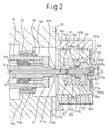
Fig. 2 is an enlarged sectional view of the rear end portion of the spindle, showing a rotary joint according to a preferred embodiment of the present invention. - The preferred embodiments of the present invention will be described below with reference to the accompanying drawings. Although the present invention is described below with reference to the embodiments, taking a horizontal machining center as an example, it is not limited to a horizontal maching center, but may also be applied to a vertical machining center.
- In
Fig. 1 , aspindle head 11 of a horizontal machining center is adapted to move up and down along a Y-axis guide rail 13 of a column (not shown) erected and fixed on a bed (not shown) making up a base. Aspindle 15, rotationally driven by a built-in motor, is rotatably supported in thespindle head 11 throughfront bearings 17a, 17b andrear bearings tool holder 21 having various tools (not shown) mounted therein can be changeably mounted in atapered hole 15 at the forward end of thespindle 15. - A housing of the
spindle head 11 is configured of afront housing 23 and arear housing 25, both of which are integrally fastened to each other with a plurality ofbolts 27. The twofront bearings 17a, 17b for rotatably supporting the front portion of thespindle 15 are provided in thefront housing 23. The inner race of the left front bearing 17a is in contact with the shoulder of thespindle 15, and the inner race of the right front bearing 17b is fixed to thespindle 15 by anut 29 through an inner race collar. The outer race of the right front bearing 17b is in contact with the shoulder of thefront housing 23, and the outer race of the left front bearing 17a is fixed by abearing holder 31 through an outer race collar. - A
bearing case 33 is fitted into ahole 35 formed in therear housing 25, and the tworear bearings spindle 15 are provided in thebearing case 33. The inner race of the left rear bearing 19a is in contact with the shoulder of thespindle 15, and the inner race of the right rear bearing 19b is fixed to thespindle 15 by anut 37 through an inner race collar. The outer race of the left rear bearing 19a is in contact with the shoulder of thebearing case 33, and the outer race of the right rear bearing 19b is fixed by abearing holder 39 through an outer race collar. - A
stator 41 of the built-in motor is provided in therear housing 25, while arotor 43 thereof is provided on the side of thespindle 15 with a minuscule radial gap between thestator 41 and therotor 43. Therotor 43 is shrinkage fitted on ashrinkage fitting sleeve 45, which in turn is shrinkage fitted on thespindle 15. - The
tool holder 21 is inserted into thetapered hole 15a at the forward end of thespindle 15, and apull stud 47 provided at the rear portion of thetool holder 21 is held by acollet 49. Thecollet 49 is retractable in the axial direction by adraw bar 51. A multiplicity ofdisk springs 55 are provided on the inner peripheral surface of thespindle 15 through asleeve 53, and the right side of thedisk springs 55 is restricted by anut 57 screwed into the rear end of thedraw bar 51 through a collar. Thedisk springs 55 apply a rearward elastic urging force to thedraw bar 51, so that thecollet 49 clamps the taper shank of thetool holder 21 in close contact with thetapered hole 15a of thespindle 15. - A draw bar driving means for pushing and driving the
draw bar 51 toward the forward end of thespindle 15 is provided in the rear of therear housing 25. The draw bar driving means includes a drawbar driving cylinder 61 mounted to the rear end of therear housing 25, and a drawbar driving piston 63 reciprocating along the central axis O hydraulically in the drawbar driving cylinder 61. Referring toFig. 2 which is an enlarged sectional view of the rear end portion of thespindle 15, the drawbar driving piston 63 is formed with acontact portion 63a projected in the form of a boss from the forward end surface (right end surface inFig. 2 ) opposed to the rear end of thespindle 15, arecess 63b formed to open rearward in the drawbar driving piston 63, and a through hole 63c extended from thecontact portion 63a to therecess 63b. The drawbar driving cylinder 61 is formed with first and secondhydraulic ports - On the other hand, the
draw bar 51 includes anextension 51b extending rearward from the rear end portion of thedraw bar 51 along the central axis O so as to be fitted slidably into the through hole 63c of the drawbar driving piston 63, and acontact shoulder 51a formed at the root of theextension 51b so as to be able to come into contact with and come away from thecontact portion 63a. Thedraw bar 51, as described above, is urged rearward by force of thedisk spring 55 in order to clamp thetool holder 21 mounted in thetapered hole 15a of thespindle 15. Once the pressured oil is supplied to the firsthydraulic port 65 of the drawbar driving cylinder 61, the drawbar driving piston 63 moves forward and thecontact portion 63a thereof comes into contact with thecontact shoulder 51a of thedraw bar 51 thereby to press thedraw bar 51 forward. As a result, thecollet 49 is moved forward through thedraw bar 51. Then, the forward end of thecollet 49 is positioned in the portion of thesleeve 53 having a large inner diameter, so that thecollet 49 is disengaged from thepull stud 47 thereby to unclamp thetool holder 21. - Further, referring to
Fig. 2 , a seal ring 69 is attached to the rear end of thedraw bar 51 and acoolant passage 51c is formed along the central axis O of thedraw bar 51. Thecoolant passage 51c is supplied with the coolant from therotary joint 100 built in the drawbar driving piston 63 as described later. This coolant is ejected from thecoolant passage 51c into the machining area between a cutting edge (not shown) of the tool T and a workpiece (not shown) through thepassages 21a and Ta formed in thetool holder 21 and the tool T, respectively. - The
rotary joint 100 includes acylinder 101 disposed in arecess 63b of the drawbar driving piston 63, and apiston 103 provided in thecylinder 101 so as to be reciprocate along the central axisO. A piston 103 is formed in a flange shape so as to be integrated with acoolant supply pipe 105, and the inner space of thecylinder 101 is divided into apneumatic chamber 107 and a spring chamber 109 by thepiston 103. Acoil spring 115 for urging thepiston 103 and thecoolant supply pipe 105 rearward is provided in the spring chamber 109. Also, apneumatic port 101a for supplying compressed air to thepneumatic chamber 107 is formed in thecylinder 101, and is connected to an external air pressure source (not shown) so that the compressed air can be supplied from the air pressure source into or discharged from thepneumatic chamber 107. - The
coolant supply pipe 105 includes aseal ring 113 attached to the forward end of thecoolant supply pipe 105 so as to face the seal ring 69 of thedraw bar 51, acoolant passage 105a formed along the central axis O, a plurality of (four in the embodiment ofFig. 2 )radial paths 105b formed so as to extend radially and open to thecoolant passage 105a at the portion adjacent to the rear end of thecoolant supply pipe 105, and acutoff valve 105c formed at the rear end of thecoolant supply pipe 105. Also, ajoint member 111 for connecting a hose (not shown) for connecting thecoolant supply pipe 105 to an external coolant supply unit (not shown) is coupled to the rear end surface of thecylinder 101. Thejoint member 111 is formed in a substantially cylindrical shape and includes aninner space 111a for accommodating the rear end portion of thecoolant supply pipe 105 including theradial passage 105b, and aninlet port 111b extending from the rear end of thejoint member 111 to theinner space 111a and coupled with an end of the hose. The inner diameter of theinlet port 111b is smaller than that of theinner space 111a, and avalve seat 111c for thecutoff valve 105c of thecoolant supply pipe 105 to sit thereon is formed between theinlet port 111b and theinner space 111a. - An operation of this embodiment will be described below.
- By supplying a working oil from an external oil pressure source (not shown) to the first
hydraulic port 65 and at the same time recovering the working oil from the secondhydraulic port 67 to the oil pressure source, the drawbar driving piston 63 advances leftward inFigs. 1 and2 . As a result, thecontact portion 63a of the drawbar driving piston 63 comes into contact with thecontact shoulder 51a of thedraw bar 51. Thedraw bar 51 advances leftward inFigs. 1 and2 against the urging force of thedisk spring 55, so that the tool T is unclamped together with thetool holder 21 mounted in the taperedhole 15a at the forward end of thespindle 15. On the contrary, by supplying the working oil to the secondhydraulic port 67 and the same time recovering the working oil from the firsthydraulic port 65, the drawbar driving piston 63 is retreated and thedraw bar 51 is moved rearward (rightward inFigs. 1 and2 ) by the urging force of thedisk spring 55. As a result, thecollet 49 at the forward end of thedraw bar 51 pulls thetool holder 21 into thetapered hole 15a while holding thepull stud 47 of thetool holder 21, so that thetool holder 21 and the tool T are clamped at the forward end of thespindle 15. - Next, before starting the machining operation with the tool T, compressed air is supplied to the
pneumatic port 101a of thecylinder 101 of the rotary joint 100, and thepiston 103 and thecoolant supply pipe 105 are urged leftward inFig. 2 against the urging force of thecoil spring 115. Theseal ring 113 attached to the forward end of thecoolant supply pipe 105 comes into contact with the seal ring 69 attached to the rear end of thedraw bar 51, so that thecoolant passage 105a of thecoolant supply pipe 105 of the rotary joint 100 communicates with thecoolant passage 51c of thedraw bar 51. At the same time, thecutoff valve 105c at the rear end of thecoolant supply pipe 105 moves away from thevalve seat 111c, and thecoolant passage 105a of thecoolant supply pipe 105 communicates with the external coolant source through theradial passage 105b and a hose (not shown) connected to theinlet port 111b of thejoint member 111. Thus, the coolant supplied from the coolant source is ejected into the machining area between the cutting edge of the tool T and the workpiece through the hose, theinlet port 111b, theradial passage 105b, thecoolant passage 105a, thecoolant passage 51c and thepassages 21a, Ta formed in thetool holder 21 and the tool T, respectively. The coolant leaking from between the twoseal rings 113, 69 flows partly into therear housing 25 through the gap between theextension 51b of thedraw bar 51 and the through hole 63c of the drawbar driving piston 63. However, the leaking coolant can be recovered by appropriately forming adrain 25a in therear housing 25. - On the other hand, the
front housing 23 is separated from therear housing 25 together with thespindle 15 through thefront bearings 17a, 17b by loosening thebolts 27 and pulling thefront housing 23 forward. In the process, thespindle 15 has attached thereto the component parts built in thespindle 15 including therotor 43, the bearingcase 33 having the rear bearing 19 built therein, thetool holder 21, thecollet 49, thedraw bar 51 and thedisk spring 55. These parts that can be removed together with thefront housing 23 are called the front housing unit. Further, thedraw bar 51 is pulled out with thespindle 15 and the seal ring 69, while at the same time separating thedraw bar 51 from thecoolant supply pipe 105. Specifically, the coolant supply passage extending from the coolant source to the machining area constituted by the hose, theinlet port 111b, theradial passage 105b, thecoolant passage 105a, thecoolant passage 51c, thepassage 21a of thetool holder 21 and the passage Ta of the tool T etc. is separated between the seal ring 69 of thedraw bar 51 and theseal ring 113 of thecoolant supply pipe 105. - Although this embodiment represents a case in which the rotary joint 100 is fixed in the
recess 63b of thepiston 63, the rotary joint 100 may be supported by a bracket from thecylinder 61 and located in therecess 63b of thepiston 63 independently of thepiston 63. - Further, although this embodiment has been described taking a structure as an example in which the front housing unit of the horizontal machining center is manually pulled off from the
rear housing 25, the present invention is not limited to this structure and can be applied to a spindle device of a vertical machining center. Specifically, a flange-equivalent member of the front housing of the vertical spindle device is fixed on a table through a jig and, using the Z-axis vertical feed motion, the front housing unit can be pulled out of the rear housing in the same manner as in the horizontal machining center. The present invention can be also applied to a multipurpose machine tool for manually performing the feed operation as well as to the machining center and the NC machine tool.
Claims (1)
- A spindle device of a machine tool having a spindle rotatably supported in a housing by a front bearing and a rear bearing, said housing including a front housing and a rear housing which are separably fastened, said front bearing of said spindle built in said front housing, said rear bearing of said spindle supported by said rear housing, said front bearing, said spindle and said rear bearing adapted to be able to be separated from said rear housing integrally with said front housing when said front housing is separated from said rear housing, said spindle device comprising:a draw bar extending in said spindle along a central axis of said spindle for clamping a tool mounted to a forward end of said spindle;a coolant passage formed to extend through said draw bar along the central axis;an unclamp unit having a draw bar driving piston for pushing said draw bar toward the forward end of said spindle along the central axis for unclamping said tool mounted to the forward end of said spindle; anda rotary joint located in a recess formed in said piston of said unclamp unit, and including a coolant supply pipe having a second seal ring attached to the forward end thereof and provided so as to be movable along the central axis of said spindle in such a manner as to come into contact with and be separated from a first seal ring attached to the rear end of said draw bar,wherein said draw bar accompanied by said first seal ring can be separated from said rear housing and said rotary joint together with said spindle and said front housing.
Applications Claiming Priority (1)
| Application Number | Priority Date | Filing Date | Title |
|---|---|---|---|
| PCT/JP2005/010093 WO2006126284A1 (en) | 2005-05-26 | 2005-05-26 | Spindle device of machine tool |
Publications (3)
| Publication Number | Publication Date |
|---|---|
| EP1958718A1 true EP1958718A1 (en) | 2008-08-20 |
| EP1958718A4 EP1958718A4 (en) | 2010-11-24 |
| EP1958718B1 EP1958718B1 (en) | 2013-08-14 |
Family
ID=37451719
Family Applications (1)
| Application Number | Title | Priority Date | Filing Date |
|---|---|---|---|
| EP05745780.6A Expired - Lifetime EP1958718B1 (en) | 2005-05-26 | 2005-05-26 | Spindle device of machine tool |
Country Status (3)
| Country | Link |
|---|---|
| US (1) | US7972096B2 (en) |
| EP (1) | EP1958718B1 (en) |
| WO (1) | WO2006126284A1 (en) |
Cited By (7)
| Publication number | Priority date | Publication date | Assignee | Title |
|---|---|---|---|---|
| US20100119316A1 (en) * | 2008-09-18 | 2010-05-13 | Cooper Power Tools Sas | Processing Machine and Associated Processing Method |
| DE102008058941A1 (en) * | 2008-11-25 | 2010-05-27 | Franz Kessler Gmbh | Machine tool i.e. cutting machine such as grinding machine, for cutting workpiece, has cooling channel running through shaft and directing coolant through shaft, where channel is partially spaced from longitudinal axis than clamping element |
| US20100272530A1 (en) * | 2009-04-22 | 2010-10-28 | Jay Christopher Rozzi | Device for Axial Delivery of Cryogenic Fluids Through a Machine Spindle |
| ITMI20101133A1 (en) * | 2010-06-23 | 2011-12-24 | Ficep Spa | PROFILE DEVICE FOR DRILLING AND MILLING |
| EP2433741A1 (en) | 2010-09-27 | 2012-03-28 | STAMA Maschinenfabrik GmbH | Machine tool with exchangeable spindle unit |
| DE102017008654A1 (en) | 2017-09-14 | 2019-03-14 | Franz Kessler Gmbh | Motor spindle for a machine tool with integrated cooling and rotary feedthrough module |
| WO2022084200A3 (en) * | 2020-10-20 | 2022-06-16 | Wto Vermögensverwaltung Gmbh | Coupling device for creating a non-permanent hydraulic connection |
Families Citing this family (18)
| Publication number | Priority date | Publication date | Assignee | Title |
|---|---|---|---|---|
| JP4846410B2 (en) * | 2006-03-30 | 2011-12-28 | シチズンホールディングス株式会社 | Spindle head device and machine tool |
| DE102006015065A1 (en) * | 2006-03-31 | 2007-10-18 | Siemens Ag | Built-in motor, in particular built-in torque motor |
| JP4488375B2 (en) * | 2007-11-22 | 2010-06-23 | 株式会社森精機製作所 | Machine tool spindle equipment |
| CN102151851B (en) * | 2011-04-25 | 2012-11-21 | 林雄 | Pneumatic thrust electric spindle |
| US8956093B1 (en) | 2011-11-11 | 2015-02-17 | Mag Ias, Llc | Seal arrangement for a high speed spindle with through the spindle cooling |
| DK2881200T3 (en) * | 2013-12-04 | 2019-04-23 | Gildemeister Drehmaschinen Gmbh | Spindle unit for turning and milling machines |
| JP6492502B2 (en) * | 2014-10-03 | 2019-04-03 | 株式会社ジェイテクト | Machine tool spindle equipment |
| JP6730912B2 (en) * | 2016-10-26 | 2020-07-29 | 三菱重工工作機械株式会社 | Spindle unit and machine tool |
| JP6962929B2 (en) * | 2016-12-12 | 2021-11-05 | シチズン時計株式会社 | Coolant fitting device |
| US11033971B2 (en) * | 2017-05-09 | 2021-06-15 | Schaublin Sa | Clamping device for holding a collet |
| DE102019102158B4 (en) * | 2019-01-29 | 2022-01-20 | Gebr. Heller Maschinenfabrik Gmbh | Facing head and method for clamping and releasing a tool in or from a tool holder of the facing head |
| WO2021095924A1 (en) * | 2019-11-14 | 2021-05-20 | 한국생산기술연구원 | Machining center for precooling cryogenic cooling tools, and control method therefor |
| CN114986730B (en) * | 2022-06-30 | 2024-06-18 | 青岛高测科技股份有限公司 | Automatic tensioning device for cutting roller of crystal silicon slicing machine, assembling method and slicing machine |
| CN116060984B (en) * | 2023-03-29 | 2023-06-27 | 湖南中大创远数控装备有限公司 | Tensioning oil cylinder structure, clamp and spiral bevel gear machine tool |
| CN116493959B (en) * | 2023-05-15 | 2026-02-27 | 大广行科技(广东)有限公司 | Four-axis machining center |
| CN118456049B (en) * | 2024-07-15 | 2024-09-10 | 冈田精机(常州)有限公司 | Long-shaft-core double-bearing direct-drive rotary table |
| CN118875332A (en) * | 2024-08-23 | 2024-11-01 | 珠海格力电器股份有限公司 | Spindle components and processing equipment for center water discharge |
| CN119115574B (en) * | 2024-11-08 | 2025-02-14 | 宁波海天精工股份有限公司 | Numerical control machine tool spindle |
Family Cites Families (17)
| Publication number | Priority date | Publication date | Assignee | Title |
|---|---|---|---|---|
| DE3714562A1 (en) * | 1987-04-30 | 1988-11-10 | Deckel Ag Friedrich | TOOL SPINDLE ARRANGEMENT WITH AN ELECTRIC DRIVE MOTOR |
| JP2836153B2 (en) * | 1990-01-17 | 1998-12-14 | ブラザー工業株式会社 | Spindle cooling device for machine tools |
| JPH042438A (en) * | 1990-04-13 | 1992-01-07 | Yamazaki Mazak Corp | Cooling structure for machine tool spindle driving motor |
| JPH07109269B2 (en) * | 1990-09-04 | 1995-11-22 | 山田興産株式会社 | Rotary joint for drawbar |
| JPH0832393B2 (en) * | 1990-11-28 | 1996-03-29 | オークマ株式会社 | Air blow structure of the spindle |
| JPH0647648A (en) * | 1992-02-05 | 1994-02-22 | Suzuki Motor Corp | Coolant feed device |
| JP2906007B2 (en) | 1993-02-12 | 1999-06-14 | 株式会社牧野フライス製作所 | Rotary joint |
| JP2559199B2 (en) | 1993-07-29 | 1996-12-04 | 本田技研工業株式会社 | Welding flue gas dust collector |
| JP2604941Y2 (en) * | 1993-12-28 | 2000-06-12 | 日立精機株式会社 | Cooling structure of main shaft of built-in motor type machine tool |
| JP3687802B2 (en) * | 1995-03-30 | 2005-08-24 | 株式会社森精機ハイテック | Rotary joint device for machine tools |
| DE19543612C1 (en) * | 1995-11-23 | 1997-05-07 | Glyco Antriebstechnik Gmbh | Clamping device with integrated fluid rotating union |
| DE29520427U1 (en) * | 1995-12-22 | 1996-02-08 | Deckel Maho Gmbh | Spindle unit for machine tools |
| JPH1133876A (en) * | 1997-07-11 | 1999-02-09 | Toyoda Mach Works Ltd | Spindle device |
| DE10027750C5 (en) * | 2000-06-03 | 2010-04-22 | Fischer Precise Deutschland Gmbh | Motor spindle for a machine tool and modular unit for such |
| JP4179775B2 (en) * | 2001-11-26 | 2008-11-12 | 株式会社牧野フライス製作所 | How to replace the spindle of a machine tool |
| KR100440156B1 (en) * | 2002-05-31 | 2004-07-12 | 현대자동차주식회사 | Spindle for machine tools |
| US7704022B2 (en) * | 2003-05-02 | 2010-04-27 | Mircea Petrescu | Motorized precision spindle apparatus |
-
2005
- 2005-05-26 US US11/914,832 patent/US7972096B2/en active Active
- 2005-05-26 WO PCT/JP2005/010093 patent/WO2006126284A1/en not_active Ceased
- 2005-05-26 EP EP05745780.6A patent/EP1958718B1/en not_active Expired - Lifetime
Cited By (15)
| Publication number | Priority date | Publication date | Assignee | Title |
|---|---|---|---|---|
| US8388282B2 (en) * | 2008-09-18 | 2013-03-05 | Cooper Power Tools Sas | Processing machine and associated processing method |
| US20100119316A1 (en) * | 2008-09-18 | 2010-05-13 | Cooper Power Tools Sas | Processing Machine and Associated Processing Method |
| DE102008058941A1 (en) * | 2008-11-25 | 2010-05-27 | Franz Kessler Gmbh | Machine tool i.e. cutting machine such as grinding machine, for cutting workpiece, has cooling channel running through shaft and directing coolant through shaft, where channel is partially spaced from longitudinal axis than clamping element |
| EP2421676A4 (en) * | 2009-04-22 | 2013-05-22 | Creare Inc | DEVICE FOR AXIAL DISTRIBUTION OF CRYOGENIC FLUIDS THROUGH A MACHINE PIN |
| US8303220B2 (en) * | 2009-04-22 | 2012-11-06 | Creare Incorporated | Device for axial delivery of cryogenic fluids through a machine spindle |
| WO2010124045A1 (en) | 2009-04-22 | 2010-10-28 | Creare Incorporated | Device for axial delivery of cryogenic fluids through a machine spindle |
| US20100272530A1 (en) * | 2009-04-22 | 2010-10-28 | Jay Christopher Rozzi | Device for Axial Delivery of Cryogenic Fluids Through a Machine Spindle |
| ITMI20101133A1 (en) * | 2010-06-23 | 2011-12-24 | Ficep Spa | PROFILE DEVICE FOR DRILLING AND MILLING |
| EP2433741A1 (en) | 2010-09-27 | 2012-03-28 | STAMA Maschinenfabrik GmbH | Machine tool with exchangeable spindle unit |
| DE102010047558A1 (en) | 2010-09-27 | 2012-03-29 | Stama Maschinenfabrik Gmbh | Machine tool with replaceable spindle unit |
| DE102010047558B4 (en) * | 2010-09-27 | 2014-12-24 | Stama Maschinenfabrik Gmbh | Machine tool with replaceable spindle unit |
| DE102017008654A1 (en) | 2017-09-14 | 2019-03-14 | Franz Kessler Gmbh | Motor spindle for a machine tool with integrated cooling and rotary feedthrough module |
| WO2022084200A3 (en) * | 2020-10-20 | 2022-06-16 | Wto Vermögensverwaltung Gmbh | Coupling device for creating a non-permanent hydraulic connection |
| CN116669897A (en) * | 2020-10-20 | 2023-08-29 | Wto资产管理有限公司 | Coupling equipment for making non-permanent hydraulic connections |
| EP4650086A3 (en) * | 2020-10-20 | 2026-02-18 | WTO Vermögensverwaltung GmbH | Coupling device for releasable production of a hydraulic connection |
Also Published As
| Publication number | Publication date |
|---|---|
| EP1958718B1 (en) | 2013-08-14 |
| US7972096B2 (en) | 2011-07-05 |
| WO2006126284A1 (en) | 2006-11-30 |
| EP1958718A4 (en) | 2010-11-24 |
| US20090053005A1 (en) | 2009-02-26 |
Similar Documents
| Publication | Publication Date | Title |
|---|---|---|
| EP1958718B1 (en) | Spindle device of machine tool | |
| JP4179775B2 (en) | How to replace the spindle of a machine tool | |
| US8376670B2 (en) | Spindle head device and machine tool | |
| JP5562410B2 (en) | Machine tool spindle equipment | |
| CN114630722B (en) | Tool clamping device and machine tool | |
| KR102427733B1 (en) | Tool turret of machine tool | |
| CN111587159B (en) | Lathe | |
| JP6778311B1 (en) | Tool post and machine tools | |
| JP4480444B2 (en) | Machine tool spindle equipment | |
| JPH07285046A (en) | Tool mounting method and machine tool for machine tool | |
| CN115175778A (en) | Long boring bar device of machine tool | |
| JP4459207B2 (en) | Spindle device of machine tool and spindle replacement method | |
| CN110248770B (en) | Spindle device of machine tool | |
| JP4765790B2 (en) | Grinding wheel attachment / detachment structure | |
| JP2009107037A (en) | Lathe spindle structure | |
| JP7372478B2 (en) | turret | |
| JP2011051064A (en) | Machine tool | |
| KR102772879B1 (en) | Workpiece ejector device for machine tools | |
| WO2003037556A1 (en) | Face clamp chuck and face clamp method | |
| JP2008049473A (en) | Aerostatic bearing spindle device | |
| JPH07205020A (en) | Spindle device equipped with grinding wheel automatic exchanging device | |
| JPH06297282A (en) | Automatic finish working apparatus for valve attaching part of cylinder head | |
| JPH10244438A (en) | Cutting oil supply device in facing equipment | |
| KR20150074734A (en) | Workpiece clamping device of spindle for machine tool |
Legal Events
| Date | Code | Title | Description |
|---|---|---|---|
| PUAI | Public reference made under article 153(3) epc to a published international application that has entered the european phase |
Free format text: ORIGINAL CODE: 0009012 |
|
| 17P | Request for examination filed |
Effective date: 20071116 |
|
| AK | Designated contracting states |
Kind code of ref document: A1 Designated state(s): DE FR GB IT |
|
| RBV | Designated contracting states (corrected) |
Designated state(s): DE FR GB IT |
|
| RBV | Designated contracting states (corrected) |
Designated state(s): DE FR GB IT |
|
| RBV | Designated contracting states (corrected) |
Designated state(s): DE FR GB IT |
|
| RBV | Designated contracting states (corrected) |
Designated state(s): DE FR GB IT |
|
| A4 | Supplementary search report drawn up and despatched |
Effective date: 20101025 |
|
| 17Q | First examination report despatched |
Effective date: 20110324 |
|
| GRAP | Despatch of communication of intention to grant a patent |
Free format text: ORIGINAL CODE: EPIDOSNIGR1 |
|
| GRAS | Grant fee paid |
Free format text: ORIGINAL CODE: EPIDOSNIGR3 |
|
| GRAA | (expected) grant |
Free format text: ORIGINAL CODE: 0009210 |
|
| AK | Designated contracting states |
Kind code of ref document: B1 Designated state(s): DE FR GB IT |
|
| REG | Reference to a national code |
Ref country code: GB Ref legal event code: FG4D |
|
| REG | Reference to a national code |
Ref country code: DE Ref legal event code: R096 Ref document number: 602005040860 Country of ref document: DE Effective date: 20131010 |
|
| PLBE | No opposition filed within time limit |
Free format text: ORIGINAL CODE: 0009261 |
|
| STAA | Information on the status of an ep patent application or granted ep patent |
Free format text: STATUS: NO OPPOSITION FILED WITHIN TIME LIMIT |
|
| 26N | No opposition filed |
Effective date: 20140515 |
|
| REG | Reference to a national code |
Ref country code: DE Ref legal event code: R097 Ref document number: 602005040860 Country of ref document: DE Effective date: 20140515 |
|
| REG | Reference to a national code |
Ref country code: FR Ref legal event code: PLFP Year of fee payment: 12 |
|
| REG | Reference to a national code |
Ref country code: FR Ref legal event code: PLFP Year of fee payment: 13 |
|
| REG | Reference to a national code |
Ref country code: FR Ref legal event code: PLFP Year of fee payment: 14 |
|
| PGFP | Annual fee paid to national office [announced via postgrant information from national office to epo] |
Ref country code: FR Payment date: 20240328 Year of fee payment: 20 |
|
| PGFP | Annual fee paid to national office [announced via postgrant information from national office to epo] |
Ref country code: GB Payment date: 20240402 Year of fee payment: 20 |
|
| PGFP | Annual fee paid to national office [announced via postgrant information from national office to epo] |
Ref country code: DE Payment date: 20240328 Year of fee payment: 20 |
|
| PGFP | Annual fee paid to national office [announced via postgrant information from national office to epo] |
Ref country code: IT Payment date: 20240411 Year of fee payment: 20 |
|
| REG | Reference to a national code |
Ref country code: DE Ref legal event code: R071 Ref document number: 602005040860 Country of ref document: DE |
|
| REG | Reference to a national code |
Ref country code: GB Ref legal event code: PE20 Expiry date: 20250525 |
|
| PG25 | Lapsed in a contracting state [announced via postgrant information from national office to epo] |
Ref country code: GB Free format text: LAPSE BECAUSE OF EXPIRATION OF PROTECTION Effective date: 20250525 |