EP1957748B1 - Procede et dispositif de positionnement de tenailles a moteur au niveau d un joint de canalisation - Google Patents
Procede et dispositif de positionnement de tenailles a moteur au niveau d un joint de canalisation Download PDFInfo
- Publication number
- EP1957748B1 EP1957748B1 EP06824344.3A EP06824344A EP1957748B1 EP 1957748 B1 EP1957748 B1 EP 1957748B1 EP 06824344 A EP06824344 A EP 06824344A EP 1957748 B1 EP1957748 B1 EP 1957748B1
- Authority
- EP
- European Patent Office
- Prior art keywords
- power tong
- pipe joint
- camera
- pipe
- positioning
- Prior art date
- Legal status (The legal status is an assumption and is not a legal conclusion. Google has not performed a legal analysis and makes no representation as to the accuracy of the status listed.)
- Not-in-force
Links
Images


Classifications
-
- E—FIXED CONSTRUCTIONS
- E21—EARTH DRILLING; MINING
- E21B—EARTH DRILLING, e.g. DEEP DRILLING; OBTAINING OIL, GAS, WATER, SOLUBLE OR MELTABLE MATERIALS OR A SLURRY OF MINERALS FROM WELLS
- E21B19/00—Handling rods, casings, tubes or the like outside the borehole, e.g. in the derrick; Apparatus for feeding the rods or cables
- E21B19/16—Connecting or disconnecting pipe couplings or joints
- E21B19/165—Control or monitoring arrangements therefor
Definitions
- This invention regards a method of positioning a power tong at a pipe joint. More particularly, it regards a method of positioning a power tong at the pipe joint of a pipe, where, after the pipe joint has been brought within the working area of a power tong, the power tong must be displaced to a position that corresponds with that of the pipe joint.
- a camera which may be displaced in parallel with the pipe, and which is linked to a display, is displaced until the image of the pipe joint coincides with a marker.
- a signal is then transmitted to a control, indicating that the power tong is to be displaced to a position that coincides with the camera and thereby the pipe joint.
- the control which receives information about the relative positions of the camera and the power tong, is programmed to guide the power tong to said position.
- the invention also regards a device for implementation of the method.
- power tongs When screwing together and unscrewing pipe strings, e.g. in connection with drilling in the ground, power tongs are typically used for the actual screwing operation.
- the positioning of the power tong, which in addition to the actual power tong also comprises a backup tong, at the pipe joint must be relatively accurate to avoid damage to the pipe couplings, and to ensure the success of the screwing operation.
- a pipe string may for instance consist of drill pipes or casing.
- pipes also includes other equipment such as drill collars or tool components that are commonly connected into a pipe string.
- the power tong is guided to the correct position by an operator near the power tong. It is also known to place sensors by the pipe string, the sensors being arranged to indicate to position of the pipe joint, so that the power tong can then automatically be guided to the correct position.
- US document 2005/0 104 583 describes an apparatus for positioning pipe joints by means of so-called eddy current. Position measuring by use of an eddy current field will only provide an approximate position report, due to the relatively "blurred” change in the eddy current field at the approach of the pipe joint.
- a further method for positioning a power tong with respect to pipe point according to the preamble of claim 1 is disclosed in US 2004/174 163 .
- Safety reasons dictate that preferably, personnel should not be present on the drill floor during the operations in question.
- sensors have turned out not to be capable of indicating the position of the pipe joint with sufficient accuracy. The reason for this is, among other things, that the sensors can hardly take into account the fact that the pipe components have been repaired or for other reasons have different dimensions.
- the object of the invention is to remedy or reduce at least one of the drawbacks of prior art.
- a camera which may be displaced in parallel with the pipe, and which is linked to a display, is displaced in the direction of the pipe joint until the image of the pipe joint coincides with a marker.
- a signal is then transmitted to a control, indicating that the power tong is to be displaced to a position that coincides with the camera and thereby the pipe joint, the control, which receives information about the relative positions of the camera and the power tong, preferably being programmed to guide the power tong to said position.
- the marker which preferably appears in the display, may be e.g. crosshairs in the display, in the camera optics or an electronically generated marker.
- the camera which is directed at the pipe string, can be displaced along a guide by means of an actuator.
- the guide is secured to a point at a fixed height relative to the power tong.
- the actuator may be an electric motor coupled to a feed screw, or it may be a hydraulic cylinder.
- the actuator is controlled by a first transducer, preferably via the control.
- the display which displays an image of the pipe string at the current vertical height of the camera, is placed near the first transducer to allow an operator to operate the first transducer based on what can be seen in the display.
- the control upon receiving a signal from the first transducer indicating that the camera is in the correct position by the pipe joint, the control will automatically guide the power tong to the desired position by the pipe joint.
- the method and device of the invention provides a reliable, remote controlled and relatively favourably priced solution for positioning a power tong at a pipe joint.
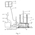
- reference number 1 denotes an assembly of a power tong 2 and a backup tong 4 arranged jointly or separately to move vertically along columns 6.
- the columns 6 are mounted on a pedestal 8, and the entire assembly 1 can be displaced on a drill floor 10.
- a pipe string 12 extends through the assembly 1.
- the power tong 2 and the backup tong 4 are arranged to make up and break the pipe joints 14 of the pipe string 12 by the tongs 2, 4 being placed on separate parts of the pipe joint 14 and gripping the pipe as the power tong 2 rotates the upper part of the pipe string 12 in the desired direction while the backup tong 4 holds the other part of the pipe string 12 still.
- a camera 16 connected to a display 18 by a line 20 is directed at the pipe string 12, the display 18 showing an image of the pipe string 12.
- the camera 16 can be displaced, preferably in parallel with the pipe string 12, by means of a guide 22.
- the camera 16 is controlled by a first transducer 24, a programmable control 26 and a motor 28 by means of a feed screw (not shown). Lines 30 connect the first transducer 24 and the motor 28 to the control 26.
- the motor 28 is provided with a second transducer 32, which in a manner that is known per se is arranged to deliver a signal to the control 26, so that the control 26 can keep track of the relative position of the camera 16.
- the control 26 is connected to the power tong 2 and the backup tong 4 via a line 34.
- the control 26 is arranged to control the displacement of the tongs 2, 4 along the columns 6, and also to keep track of the relative positions of the tongs 2, 4 by means of signals from a third transducer 36 and a fourth transducer 38.
- the first transducer 24 When the pipe joint 14 of the pipe string 12 is within the working area of the tongs 2, 4, see figure 1 , the first transducer 24 is operated, whereupon the camera 16 is displaced in the direction of the pipe joint 14 until the pipe joint 14, more particularly visible break between the parts of the pipe joint 14, coincides with a marker 40 in the display 18, see figure 2 .
- a signal is transmitted to the control 26 via the first transducer 24, instructing the tongs 2, 4 to move, preferably automatically, along the pipe string 12 to a position that corresponds with that of the camera 16. This position coincides with the position of the pipe joint 14; see figure 3 , whereupon a pipe string portion can be uncoupled from a pipe string 12 in a manner that is known per se.
Claims (5)
- Une méthode de positionnement de clé de vissage automatique (2) à une jonction de tuyau (14) d'un train de tuyaux (12) après que la jonction de tuyau (14) a été amenée dans la zone de travail de la clé de vissage automatique (2), caractérisée en ce que la méthode comprend:- déplacer une caméra (16), qui est reliée à un écran (18), le long d'un guide fixé à une hauteur fixée relative à la clé de vissage automatique (2) et en parallèle avec le tuyau (12) jusqu'à ce qu'une image de la jonction de tuyau (14) coïncide avec un repère (40) dans l'écran (18), et puis transmettre un signal à un dispositif de commande (26) connecté à la clé de vissage automatique (2); et- à base du signal, déplacer la clé de vissage automatique (2) à une position qui correspond avec celle de la caméra (16) et ainsi la jonction de tuyau (14).
- Une méthode selon la revendication 1, dans laquelle le dispositif de commande (26), qui reçoit l'information sur les positions relatives de la caméra (16) et de la clé de vissage automatique (2), guide automatiquement la clé de vissage automatique (2) à la position correcte.
- Un dispositif de positionnement pour de positionner une clé de vissage automatique (2) à une jonction de tuyau (14) d'un train de tuyaux (12) après que la jonction de tuyau (14) à été amenée dans la zone de travail de la clé de vissage automatique (2), caractérisé en ce que le dispositif de positionnement comprend:- une caméra (16) qui est déplaçable le long d'un guide fixé à une hauteur fixée relative à la clé de vissage automatique (2), la caméra étant reliée à un écran (18);- et un actionneur pour déplacer la caméra (16) le long du guide (22) en parallèle avec le tuyau (12); dans lequel la caméra est arrangée pour être déplacée jusqu'à ce que l'image de la jonction de tuyau (14) coïncide avec un repère (40) dans l'écran (18); et un premier transducteur (24) connecté à un dispositif de commande (26) pour la clé de vissage automatique (2) est arrangé pour transmettre un signal au dispositif de commande (26) pour déplacer la clé de vissage automatique (2) à une position qui correspond avec celle de la jonction de tuyau (14).
- Un dispositif selon la revendication 3, dans lequel la caméra (16) est déplacée par un moteur électrique (28).
- Un dispositif selon la revendication 3, dans lequel la caméra (16) est déplacée par un cylindre hydraulique.
Applications Claiming Priority (2)
| Application Number | Priority Date | Filing Date | Title |
|---|---|---|---|
| NO20055576A NO20055576A (no) | 2005-11-25 | 2005-11-25 | Fremgangsmåte og anordning for å posisjonere en krafttang ved en rørskjøt |
| PCT/NO2006/000425 WO2007061315A1 (fr) | 2005-11-25 | 2006-11-23 | Procede et dispositif de positionnement de tenailles a moteur au niveau d’un joint de canalisation |
Publications (3)
| Publication Number | Publication Date |
|---|---|
| EP1957748A1 EP1957748A1 (fr) | 2008-08-20 |
| EP1957748A4 EP1957748A4 (fr) | 2014-10-22 |
| EP1957748B1 true EP1957748B1 (fr) | 2015-07-29 |
Family
ID=35529562
Family Applications (1)
| Application Number | Title | Priority Date | Filing Date |
|---|---|---|---|
| EP06824344.3A Not-in-force EP1957748B1 (fr) | 2005-11-25 | 2006-11-23 | Procede et dispositif de positionnement de tenailles a moteur au niveau d un joint de canalisation |
Country Status (10)
| Country | Link |
|---|---|
| US (1) | US8065937B2 (fr) |
| EP (1) | EP1957748B1 (fr) |
| CN (1) | CN101365859B (fr) |
| AU (1) | AU2006317785B2 (fr) |
| BR (1) | BRPI0618991B1 (fr) |
| CA (1) | CA2630787C (fr) |
| DK (1) | DK1957748T3 (fr) |
| EA (1) | EA011912B1 (fr) |
| NO (1) | NO20055576A (fr) |
| WO (1) | WO2007061315A1 (fr) |
Families Citing this family (16)
| Publication number | Priority date | Publication date | Assignee | Title |
|---|---|---|---|---|
| US9297223B2 (en) | 2008-02-12 | 2016-03-29 | Warrior Rig Ltd. | Top drive with slewing power transmission |
| US8109179B2 (en) | 2008-02-12 | 2012-02-07 | Allan Stewart Richardson | Power tong |
| GB201007200D0 (en) * | 2010-04-29 | 2010-06-16 | Nat Oilwell Varco Lp | Videometric system and method for offshore and oil-well drilling |
| DE102010060823A1 (de) * | 2010-11-26 | 2012-05-31 | Bentec Gmbh Drilling & Oilfield Systems | Verfahren und Vorrichtung zur halbautomatischen Justierung einer Handhabungseinrichtung |
| US9322950B2 (en) | 2011-09-29 | 2016-04-26 | Voca As | Method and apparatus for finding stick-up height of a pipe or finding a joint between two pipes in a drilling environment |
| DE102012208676A1 (de) * | 2012-05-23 | 2013-11-28 | Bentec Gmbh Drilling & Oilfield Systems | Verfahren und Vorrichtung zur halbautomatischen Justierung einer Handhabungseinrichtung |
| US9453377B2 (en) * | 2013-10-21 | 2016-09-27 | Frank's International, Llc | Electric tong system and methods of use |
| GB2532267A (en) * | 2014-11-14 | 2016-05-18 | Nat Oilwell Varco Norway As | A method for placing and removing pipe from a finger rack |
| US10087745B2 (en) | 2015-04-27 | 2018-10-02 | Cameron International Corporation | Bore object characterization system for well assemblies |
| RU2019100105A (ru) * | 2016-06-13 | 2020-07-14 | Шлюмбергер Текнолоджи Б.В. | Вспомогательный механизм замкового соединения |
| US10366507B2 (en) * | 2017-08-18 | 2019-07-30 | Weatherford Technology Holdings, Llc | Optical imaging and assessment system for tong cassette positioning device |
| US10995570B2 (en) | 2017-10-20 | 2021-05-04 | Weatherford Technology Holdings, Llc | Tool joint finding apparatus and method |
| US11060381B2 (en) | 2018-08-22 | 2021-07-13 | Weatherford Technology Holdings Llc | Tong cassette positioning device |
| WO2020118014A1 (fr) | 2018-12-07 | 2020-06-11 | Nabors Drilling Technologies Usa, Inc. | Systèmes et procédés de surveillance de trains de tiges de forage |
| WO2020176485A1 (fr) * | 2019-02-26 | 2020-09-03 | Cameron International Corporation | Aide de raccords de tige pour aide-foreur mécanique |
| US10975681B2 (en) | 2019-04-09 | 2021-04-13 | Weatherford Technology Holdings, Llc | Apparatus and method for locating tool joint |
Family Cites Families (61)
| Publication number | Priority date | Publication date | Assignee | Title |
|---|---|---|---|---|
| US2459499A (en) * | 1943-12-17 | 1949-01-18 | Schlumberger Well Surv Corp | Casing joint locator |
| US2692059A (en) * | 1953-07-15 | 1954-10-19 | Standard Oil Dev Co | Device for positioning pipe in a drilling derrick |
| GB875127A (en) * | 1956-09-24 | 1961-08-16 | F N R D Ltd | Improvements in or relating to earth drilling rigs |
| US3017621A (en) * | 1956-12-31 | 1962-01-16 | Martin Marietta Corp | Proximity limit position detector |
| US3103976A (en) * | 1961-05-10 | 1963-09-17 | Shell Oil Co | Pipe joint locator for underwater wells |
| US3273054A (en) * | 1961-11-16 | 1966-09-13 | C W Fuelling Inc | Pipe joint locator comprising mobile transformer utilizing the pipe as low reluctance path between primary and secondary |
| US3336572A (en) * | 1965-04-29 | 1967-08-15 | Texaco Inc | Sonic means and method for locating and introducing equipment into a submarine well |
| US3434046A (en) * | 1965-12-20 | 1969-03-18 | Halliburton Co | Electronic borehole casing collar locator |
| US3475038A (en) * | 1968-01-08 | 1969-10-28 | Lee Matherne | Pipe stabber with setscrews |
| US3561811A (en) * | 1968-05-23 | 1971-02-09 | Byron Jackson Inc | Well pipe racker |
| US3570594A (en) * | 1969-03-13 | 1971-03-16 | Howell M Hamilton | Subsurface control apparatus for use in oil and gas wells |
| US3780815A (en) * | 1972-01-07 | 1973-12-25 | Byron Jackson Inc | Power tong positioning apparatus |
| US3881375A (en) * | 1972-12-12 | 1975-05-06 | Borg Warner | Pipe tong positioning system |
| US3843923A (en) * | 1973-07-05 | 1974-10-22 | Stewart & Stevenson Inc Jim | Well pipe joint locator using a ring magnet and two sets of hall detectors surrounding the pipe |
| US4120095A (en) * | 1975-09-02 | 1978-10-17 | Lebourg Maurice P | Method and apparatus for determining the spatial relationship between two misaligned tubular members |
| US4148013A (en) * | 1975-12-19 | 1979-04-03 | The Indikon Company, Inc. | Rotating shaft alignment monitor |
| US4110688A (en) * | 1976-09-20 | 1978-08-29 | Monitoring Systems, Inc. | Method and apparatus for pipe joint locator, counter and displacement calculator |
| US4202225A (en) * | 1977-03-15 | 1980-05-13 | Sheldon Loren B | Power tongs control arrangement |
| US4327261A (en) * | 1977-03-15 | 1982-04-27 | Bj-Hughes Inc. | Apparatus for sensing a distended location on a drill pipe |
| US4140991A (en) * | 1977-08-15 | 1979-02-20 | The United States Of America As Represented By The Secretary Of The Navy | Underwater displacement probe |
| DE2815705C2 (de) * | 1978-04-12 | 1986-10-16 | Rolf 3100 Celle Rüße | Verfahren und Vorrichtung zum Zentrieren von Futterrohren |
| US4214842A (en) * | 1978-04-27 | 1980-07-29 | Deep Oil Technology, Inc. | Remotely controlled maneuverable tool means and method for positioning the end of a pipe string in offshore well operations |
| CA1150234A (fr) | 1979-04-30 | 1983-07-19 | Eckel Manufacturing Company, Inc. | Cles mecaniques de devissage, et mode d'emploi connexe |
| US4403666A (en) * | 1981-06-01 | 1983-09-13 | Walker-Neer Manufacturing Co. Inc. | Self centering tongs and transfer arm for drilling apparatus |
| FR2517068B1 (fr) * | 1981-11-24 | 1985-10-11 | Inst Francais Du Petrole | Methode et dispositif pour mettre dans une position relative determinee deux elements immerges dans un milieu liquide conducteur |
| US4565003A (en) * | 1984-01-11 | 1986-01-21 | Phillips Petroleum Company | Pipe alignment apparatus |
| FR2559540B1 (fr) * | 1984-02-10 | 1986-07-04 | Gazel Anthoine G | Procede et dispositif pour le pilotage de la course de levage sur un mat ou une tour de forage |
| US4528757A (en) | 1984-06-18 | 1985-07-16 | Exxon Production Research Co. | Remotely operable apparatus and method for determining the distance and angular orientation between two structurally unconnected members |
| US4821814A (en) * | 1987-04-02 | 1989-04-18 | 501 W-N Apache Corporation | Top head drive assembly for earth drilling machine and components thereof |
| US4832530A (en) * | 1988-02-08 | 1989-05-23 | Andersen Scott F | Apparatus and method for joining pipe sections underwater |
| NO163973C (no) | 1988-04-19 | 1990-08-15 | Maritime Hydraulics As | Momenttanganordning. |
| US4964462A (en) * | 1989-08-09 | 1990-10-23 | Smith Michael L | Tubing collar position sensing apparatus, and associated methods, for use with a snubbing unit |
| US5014781A (en) * | 1989-08-09 | 1991-05-14 | Smith Michael L | Tubing collar position sensing apparatus, and associated methods, for use with a snubbing unit |
| US5054550A (en) * | 1990-05-24 | 1991-10-08 | W-N Apache Corporation | Centering spinning for down hole tubulars |
| FR2663576B1 (fr) * | 1990-06-20 | 1992-10-09 | Framatome Sa | Adaptateur pour le vissage ou le devissage d'un element de liaison filete. |
| US5249208A (en) * | 1990-11-09 | 1993-09-28 | Frank Ruzga | Automatic pressure vessel servicing apparatus |
| GB9107813D0 (en) * | 1991-04-12 | 1991-05-29 | Weatherford Lamb | Tong |
| GB9107788D0 (en) * | 1991-04-12 | 1991-05-29 | Weatherford Lamb | Power tong for releasing tight joints |
| GB9205211D0 (en) | 1992-03-11 | 1992-04-22 | Weatherford Lamb | Automatic torque wrenching machine |
| US5390568A (en) * | 1992-03-11 | 1995-02-21 | Weatherford/Lamb, Inc. | Automatic torque wrenching machine |
| US5361838A (en) * | 1993-11-01 | 1994-11-08 | Halliburton Company | Slick line casing and tubing joint locator apparatus and associated methods |
| US5429190A (en) * | 1993-11-01 | 1995-07-04 | Halliburton Company | Slick line casing and tubing joint locator apparatus and associated methods |
| US5750896A (en) * | 1994-07-22 | 1998-05-12 | Hughes Aircraft Company | Tool joint sensor |
| US5720345A (en) * | 1996-02-05 | 1998-02-24 | Applied Technologies Associates, Inc. | Casing joint detector |
| US5626192A (en) * | 1996-02-20 | 1997-05-06 | Halliburton Energy Services, Inc. | Coiled tubing joint locator and methods |
| US5842390A (en) * | 1996-02-28 | 1998-12-01 | Frank's Casing Crew And Rental Tools Inc. | Dual string backup tong |
| US6360633B2 (en) * | 1997-01-29 | 2002-03-26 | Weatherford/Lamb, Inc. | Apparatus and method for aligning tubulars |
| GB9701758D0 (en) | 1997-01-29 | 1997-03-19 | Weatherford Lamb | Apparatus and method for aligning tubulars |
| US6032739A (en) * | 1998-08-15 | 2000-03-07 | Newman; Frederic M. | Method of locating wellbore casing collars using dual-purpose magnet |
| US6253842B1 (en) * | 1998-09-01 | 2001-07-03 | Halliburton Energy Services, Inc. | Wireless coiled tubing joint locator |
| US6318214B1 (en) * | 1998-12-01 | 2001-11-20 | David A. Buck | Power tong positioning apparatus |
| GB2346577B (en) | 1999-01-28 | 2003-08-13 | Weatherford Lamb | An apparatus and a method for facilitating the connection of pipes |
| US6411084B1 (en) * | 1999-04-05 | 2002-06-25 | Halliburton Energy Services, Inc. | Magnetically activated well tool |
| US6223629B1 (en) * | 1999-07-08 | 2001-05-01 | Daniel S. Bangert | Closed-head power tongs |
| US6814149B2 (en) * | 1999-11-26 | 2004-11-09 | Weatherford/Lamb, Inc. | Apparatus and method for positioning a tubular relative to a tong |
| GB2371509B (en) * | 2001-01-24 | 2004-01-28 | Weatherford Lamb | Joint detection system |
| US6720764B2 (en) * | 2002-04-16 | 2004-04-13 | Thomas Energy Services Inc. | Magnetic sensor system useful for detecting tool joints in a downhold tubing string |
| US6752044B2 (en) * | 2002-05-06 | 2004-06-22 | Frank's International, Inc. | Power tong assembly and method |
| US6968230B2 (en) * | 2002-06-26 | 2005-11-22 | Medtronic Physio-Control Manufacturing Corp | H-bridge circuit for generating a high-energy biphasic and external pacing waveform in an external defibrillator |
| US20040174163A1 (en) * | 2003-03-06 | 2004-09-09 | Rogers Tommie L. | Apparatus and method for determining the position of the end of a threaded connection, and for positioning a power tong relative thereto |
| US20080307930A1 (en) * | 2007-06-18 | 2008-12-18 | Veverica Jon A | Wrap around tong and method |
-
2005
- 2005-11-25 NO NO20055576A patent/NO20055576A/no not_active IP Right Cessation
-
2006
- 2006-11-23 BR BRPI0618991-1A patent/BRPI0618991B1/pt not_active IP Right Cessation
- 2006-11-23 US US12/094,767 patent/US8065937B2/en not_active Expired - Fee Related
- 2006-11-23 CA CA2630787A patent/CA2630787C/fr not_active Expired - Fee Related
- 2006-11-23 AU AU2006317785A patent/AU2006317785B2/en not_active Ceased
- 2006-11-23 WO PCT/NO2006/000425 patent/WO2007061315A1/fr active Application Filing
- 2006-11-23 CN CN200680044026XA patent/CN101365859B/zh not_active Expired - Fee Related
- 2006-11-23 EP EP06824344.3A patent/EP1957748B1/fr not_active Not-in-force
- 2006-11-23 DK DK06824344.3T patent/DK1957748T3/en active
- 2006-11-23 EA EA200801419A patent/EA011912B1/ru not_active IP Right Cessation
Also Published As
| Publication number | Publication date |
|---|---|
| CA2630787C (fr) | 2012-10-09 |
| EA011912B1 (ru) | 2009-06-30 |
| CA2630787A1 (fr) | 2007-05-31 |
| BRPI0618991B1 (pt) | 2017-10-31 |
| DK1957748T3 (en) | 2015-10-26 |
| US8065937B2 (en) | 2011-11-29 |
| CN101365859A (zh) | 2009-02-11 |
| US20080282847A1 (en) | 2008-11-20 |
| AU2006317785A1 (en) | 2007-05-31 |
| AU2006317785B2 (en) | 2009-12-17 |
| NO20055576D0 (no) | 2005-11-25 |
| WO2007061315A1 (fr) | 2007-05-31 |
| NO323151B1 (no) | 2007-01-08 |
| EP1957748A4 (fr) | 2014-10-22 |
| EA200801419A1 (ru) | 2008-12-30 |
| BRPI0618991A2 (pt) | 2011-09-20 |
| CN101365859B (zh) | 2013-04-03 |
| NO20055576A (no) | 2007-01-08 |
| EP1957748A1 (fr) | 2008-08-20 |
Similar Documents
| Publication | Publication Date | Title |
|---|---|---|
| EP1957748B1 (fr) | Procede et dispositif de positionnement de tenailles a moteur au niveau d un joint de canalisation | |
| EP3334890B1 (fr) | Détection et alignement d'outil pour mise en place d'outil | |
| CN102016224B (zh) | 管件下送工具及使用方法 | |
| EP1956184B1 (fr) | Procédé et appareil de connection de pipeline | |
| CN101336332B (zh) | 运行控制线连同管状钻柱的方法 | |
| US20130249703A1 (en) | Apparatus, System, And Method For Communicating While Logging With Wired Drill Pipe | |
| CA2465530A1 (fr) | Systeme automatise de raccordement de tuyaux | |
| GB2428817A (en) | Tubular running apparatus | |
| KR102252931B1 (ko) | 휴대용 토사 천공장치 및 이를 이용한 매설설비 확인 보수방법과 안전접지 시공 방법 | |
| NO335074B1 (no) | Apparat og fremgangsmåte for posisjonering av en styreledning. | |
| US8517634B1 (en) | Systems and methods for replacing, repositioning and repairing a section of subsea pipe located on a seabed | |
| EP2176492B1 (fr) | Procédé et appareil de forage de trou dans un substrat rocheux | |
| EP3841274B1 (fr) | Appareil et procédés pour déterminer le mode de fonctionnement d'un ensemble clé | |
| US20130220367A1 (en) | Method and Device for Treatment of a Pipestring Section that is Positioned in a Set-Back |
Legal Events
| Date | Code | Title | Description |
|---|---|---|---|
| PUAI | Public reference made under article 153(3) epc to a published international application that has entered the european phase |
Free format text: ORIGINAL CODE: 0009012 |
|
| 17P | Request for examination filed |
Effective date: 20080618 |
|
| AK | Designated contracting states |
Kind code of ref document: A1 Designated state(s): AT BE BG CH CY CZ DE DK EE ES FI FR GB GR HU IE IS IT LI LT LU LV MC NL PL PT RO SE SI SK TR |
|
| RAP1 | Party data changed (applicant data changed or rights of an application transferred) |
Owner name: WEATHERFORD RIG SYSTEM AS |
|
| RAP1 | Party data changed (applicant data changed or rights of an application transferred) |
Owner name: WEATHERFORD RIG SYSTEM AS |
|
| RAP1 | Party data changed (applicant data changed or rights of an application transferred) |
Owner name: WEATHERFORD RIG SYSTEMS AS |
|
| DAX | Request for extension of the european patent (deleted) | ||
| A4 | Supplementary search report drawn up and despatched |
Effective date: 20140919 |
|
| RIC1 | Information provided on ipc code assigned before grant |
Ipc: E21B 19/20 20060101ALI20140915BHEP Ipc: E21B 19/16 20060101AFI20140915BHEP |
|
| 17Q | First examination report despatched |
Effective date: 20141015 |
|
| GRAP | Despatch of communication of intention to grant a patent |
Free format text: ORIGINAL CODE: EPIDOSNIGR1 |
|
| INTG | Intention to grant announced |
Effective date: 20150515 |
|
| GRAS | Grant fee paid |
Free format text: ORIGINAL CODE: EPIDOSNIGR3 |
|
| GRAA | (expected) grant |
Free format text: ORIGINAL CODE: 0009210 |
|
| AK | Designated contracting states |
Kind code of ref document: B1 Designated state(s): AT BE BG CH CY CZ DE DK EE ES FI FR GB GR HU IE IS IT LI LT LU LV MC NL PL PT RO SE SI SK TR |
|
| REG | Reference to a national code |
Ref country code: GB Ref legal event code: FG4D |
|
| REG | Reference to a national code |
Ref country code: CH Ref legal event code: EP |
|
| REG | Reference to a national code |
Ref country code: AT Ref legal event code: REF Ref document number: 739459 Country of ref document: AT Kind code of ref document: T Effective date: 20150815 |
|
| REG | Reference to a national code |
Ref country code: IE Ref legal event code: FG4D |
|
| REG | Reference to a national code |
Ref country code: DE Ref legal event code: R096 Ref document number: 602006046139 Country of ref document: DE |
|
| REG | Reference to a national code |
Ref country code: DK Ref legal event code: T3 Effective date: 20151023 |
|
| REG | Reference to a national code |
Ref country code: AT Ref legal event code: MK05 Ref document number: 739459 Country of ref document: AT Kind code of ref document: T Effective date: 20150729 |
|
| REG | Reference to a national code |
Ref country code: LT Ref legal event code: MG4D |
|
| REG | Reference to a national code |
Ref country code: NL Ref legal event code: FP |
|
| PG25 | Lapsed in a contracting state [announced via postgrant information from national office to epo] |
Ref country code: FI Free format text: LAPSE BECAUSE OF FAILURE TO SUBMIT A TRANSLATION OF THE DESCRIPTION OR TO PAY THE FEE WITHIN THE PRESCRIBED TIME-LIMIT Effective date: 20150729 Ref country code: GR Free format text: LAPSE BECAUSE OF FAILURE TO SUBMIT A TRANSLATION OF THE DESCRIPTION OR TO PAY THE FEE WITHIN THE PRESCRIBED TIME-LIMIT Effective date: 20151030 Ref country code: LV Free format text: LAPSE BECAUSE OF FAILURE TO SUBMIT A TRANSLATION OF THE DESCRIPTION OR TO PAY THE FEE WITHIN THE PRESCRIBED TIME-LIMIT Effective date: 20150729 Ref country code: LT Free format text: LAPSE BECAUSE OF FAILURE TO SUBMIT A TRANSLATION OF THE DESCRIPTION OR TO PAY THE FEE WITHIN THE PRESCRIBED TIME-LIMIT Effective date: 20150729 |
|
| PG25 | Lapsed in a contracting state [announced via postgrant information from national office to epo] |
Ref country code: ES Free format text: LAPSE BECAUSE OF FAILURE TO SUBMIT A TRANSLATION OF THE DESCRIPTION OR TO PAY THE FEE WITHIN THE PRESCRIBED TIME-LIMIT Effective date: 20150729 Ref country code: AT Free format text: LAPSE BECAUSE OF FAILURE TO SUBMIT A TRANSLATION OF THE DESCRIPTION OR TO PAY THE FEE WITHIN THE PRESCRIBED TIME-LIMIT Effective date: 20150729 Ref country code: IS Free format text: LAPSE BECAUSE OF FAILURE TO SUBMIT A TRANSLATION OF THE DESCRIPTION OR TO PAY THE FEE WITHIN THE PRESCRIBED TIME-LIMIT Effective date: 20151129 Ref country code: PT Free format text: LAPSE BECAUSE OF FAILURE TO SUBMIT A TRANSLATION OF THE DESCRIPTION OR TO PAY THE FEE WITHIN THE PRESCRIBED TIME-LIMIT Effective date: 20151130 Ref country code: PL Free format text: LAPSE BECAUSE OF FAILURE TO SUBMIT A TRANSLATION OF THE DESCRIPTION OR TO PAY THE FEE WITHIN THE PRESCRIBED TIME-LIMIT Effective date: 20150729 Ref country code: SE Free format text: LAPSE BECAUSE OF FAILURE TO SUBMIT A TRANSLATION OF THE DESCRIPTION OR TO PAY THE FEE WITHIN THE PRESCRIBED TIME-LIMIT Effective date: 20150729 |
|
| PG25 | Lapsed in a contracting state [announced via postgrant information from national office to epo] |
Ref country code: IT Free format text: LAPSE BECAUSE OF FAILURE TO SUBMIT A TRANSLATION OF THE DESCRIPTION OR TO PAY THE FEE WITHIN THE PRESCRIBED TIME-LIMIT Effective date: 20150729 Ref country code: SK Free format text: LAPSE BECAUSE OF FAILURE TO SUBMIT A TRANSLATION OF THE DESCRIPTION OR TO PAY THE FEE WITHIN THE PRESCRIBED TIME-LIMIT Effective date: 20150729 Ref country code: EE Free format text: LAPSE BECAUSE OF FAILURE TO SUBMIT A TRANSLATION OF THE DESCRIPTION OR TO PAY THE FEE WITHIN THE PRESCRIBED TIME-LIMIT Effective date: 20150729 Ref country code: CZ Free format text: LAPSE BECAUSE OF FAILURE TO SUBMIT A TRANSLATION OF THE DESCRIPTION OR TO PAY THE FEE WITHIN THE PRESCRIBED TIME-LIMIT Effective date: 20150729 |
|
| REG | Reference to a national code |
Ref country code: DE Ref legal event code: R097 Ref document number: 602006046139 Country of ref document: DE |
|
| PG25 | Lapsed in a contracting state [announced via postgrant information from national office to epo] |
Ref country code: RO Free format text: LAPSE BECAUSE OF FAILURE TO SUBMIT A TRANSLATION OF THE DESCRIPTION OR TO PAY THE FEE WITHIN THE PRESCRIBED TIME-LIMIT Effective date: 20150729 |
|
| PLBE | No opposition filed within time limit |
Free format text: ORIGINAL CODE: 0009261 |
|
| STAA | Information on the status of an ep patent application or granted ep patent |
Free format text: STATUS: NO OPPOSITION FILED WITHIN TIME LIMIT |
|
| PG25 | Lapsed in a contracting state [announced via postgrant information from national office to epo] |
Ref country code: MC Free format text: LAPSE BECAUSE OF FAILURE TO SUBMIT A TRANSLATION OF THE DESCRIPTION OR TO PAY THE FEE WITHIN THE PRESCRIBED TIME-LIMIT Effective date: 20150729 Ref country code: LU Free format text: LAPSE BECAUSE OF FAILURE TO SUBMIT A TRANSLATION OF THE DESCRIPTION OR TO PAY THE FEE WITHIN THE PRESCRIBED TIME-LIMIT Effective date: 20151123 |
|
| REG | Reference to a national code |
Ref country code: CH Ref legal event code: PL |
|
| 26N | No opposition filed |
Effective date: 20160502 |
|
| PG25 | Lapsed in a contracting state [announced via postgrant information from national office to epo] |
Ref country code: CH Free format text: LAPSE BECAUSE OF NON-PAYMENT OF DUE FEES Effective date: 20151130 Ref country code: LI Free format text: LAPSE BECAUSE OF NON-PAYMENT OF DUE FEES Effective date: 20151130 |
|
| REG | Reference to a national code |
Ref country code: IE Ref legal event code: MM4A |
|
| REG | Reference to a national code |
Ref country code: FR Ref legal event code: ST Effective date: 20160729 |
|
| PG25 | Lapsed in a contracting state [announced via postgrant information from national office to epo] |
Ref country code: SI Free format text: LAPSE BECAUSE OF FAILURE TO SUBMIT A TRANSLATION OF THE DESCRIPTION OR TO PAY THE FEE WITHIN THE PRESCRIBED TIME-LIMIT Effective date: 20150729 |
|
| PG25 | Lapsed in a contracting state [announced via postgrant information from national office to epo] |
Ref country code: IE Free format text: LAPSE BECAUSE OF NON-PAYMENT OF DUE FEES Effective date: 20151123 |
|
| PG25 | Lapsed in a contracting state [announced via postgrant information from national office to epo] |
Ref country code: FR Free format text: LAPSE BECAUSE OF NON-PAYMENT OF DUE FEES Effective date: 20151130 |
|
| PG25 | Lapsed in a contracting state [announced via postgrant information from national office to epo] |
Ref country code: BE Free format text: LAPSE BECAUSE OF FAILURE TO SUBMIT A TRANSLATION OF THE DESCRIPTION OR TO PAY THE FEE WITHIN THE PRESCRIBED TIME-LIMIT Effective date: 20150729 |
|
| PG25 | Lapsed in a contracting state [announced via postgrant information from national office to epo] |
Ref country code: BG Free format text: LAPSE BECAUSE OF FAILURE TO SUBMIT A TRANSLATION OF THE DESCRIPTION OR TO PAY THE FEE WITHIN THE PRESCRIBED TIME-LIMIT Effective date: 20150729 Ref country code: HU Free format text: LAPSE BECAUSE OF FAILURE TO SUBMIT A TRANSLATION OF THE DESCRIPTION OR TO PAY THE FEE WITHIN THE PRESCRIBED TIME-LIMIT; INVALID AB INITIO Effective date: 20061123 |
|
| PG25 | Lapsed in a contracting state [announced via postgrant information from national office to epo] |
Ref country code: CY Free format text: LAPSE BECAUSE OF FAILURE TO SUBMIT A TRANSLATION OF THE DESCRIPTION OR TO PAY THE FEE WITHIN THE PRESCRIBED TIME-LIMIT Effective date: 20150729 |
|
| PG25 | Lapsed in a contracting state [announced via postgrant information from national office to epo] |
Ref country code: TR Free format text: LAPSE BECAUSE OF FAILURE TO SUBMIT A TRANSLATION OF THE DESCRIPTION OR TO PAY THE FEE WITHIN THE PRESCRIBED TIME-LIMIT Effective date: 20150729 |
|
| PGFP | Annual fee paid to national office [announced via postgrant information from national office to epo] |
Ref country code: NL Payment date: 20171115 Year of fee payment: 12 Ref country code: DK Payment date: 20171110 Year of fee payment: 12 |
|
| PGFP | Annual fee paid to national office [announced via postgrant information from national office to epo] |
Ref country code: DE Payment date: 20181113 Year of fee payment: 13 |
|
| PGFP | Annual fee paid to national office [announced via postgrant information from national office to epo] |
Ref country code: GB Payment date: 20181001 Year of fee payment: 13 |
|
| REG | Reference to a national code |
Ref country code: DK Ref legal event code: EBP Effective date: 20181130 |
|
| REG | Reference to a national code |
Ref country code: NL Ref legal event code: MM Effective date: 20181201 |
|
| PG25 | Lapsed in a contracting state [announced via postgrant information from national office to epo] |
Ref country code: NL Free format text: LAPSE BECAUSE OF NON-PAYMENT OF DUE FEES Effective date: 20181201 |
|
| PG25 | Lapsed in a contracting state [announced via postgrant information from national office to epo] |
Ref country code: DK Free format text: LAPSE BECAUSE OF NON-PAYMENT OF DUE FEES Effective date: 20181130 |
|
| REG | Reference to a national code |
Ref country code: DE Ref legal event code: R119 Ref document number: 602006046139 Country of ref document: DE |
|
| GBPC | Gb: european patent ceased through non-payment of renewal fee |
Effective date: 20191123 |
|
| PG25 | Lapsed in a contracting state [announced via postgrant information from national office to epo] |
Ref country code: GB Free format text: LAPSE BECAUSE OF NON-PAYMENT OF DUE FEES Effective date: 20191123 Ref country code: DE Free format text: LAPSE BECAUSE OF NON-PAYMENT OF DUE FEES Effective date: 20200603 |