EP1957322B1 - Piece d'habillage - Google Patents
Piece d'habillage Download PDFInfo
- Publication number
- EP1957322B1 EP1957322B1 EP20060841848 EP06841848A EP1957322B1 EP 1957322 B1 EP1957322 B1 EP 1957322B1 EP 20060841848 EP20060841848 EP 20060841848 EP 06841848 A EP06841848 A EP 06841848A EP 1957322 B1 EP1957322 B1 EP 1957322B1
- Authority
- EP
- European Patent Office
- Prior art keywords
- notch
- skin
- opening
- foam
- bonding layer
- Prior art date
- Legal status (The legal status is an assumption and is not a legal conclusion. Google has not performed a legal analysis and makes no representation as to the accuracy of the status listed.)
- Active
Links
Images

Classifications
-
- B—PERFORMING OPERATIONS; TRANSPORTING
- B60—VEHICLES IN GENERAL
- B60R—VEHICLES, VEHICLE FITTINGS, OR VEHICLE PARTS, NOT OTHERWISE PROVIDED FOR
- B60R13/00—Elements for body-finishing, identifying, or decorating; Arrangements or adaptations for advertising purposes
- B60R13/02—Internal Trim mouldings ; Internal Ledges; Wall liners for passenger compartments; Roof liners
-
- B—PERFORMING OPERATIONS; TRANSPORTING
- B29—WORKING OF PLASTICS; WORKING OF SUBSTANCES IN A PLASTIC STATE IN GENERAL
- B29C—SHAPING OR JOINING OF PLASTICS; SHAPING OF MATERIAL IN A PLASTIC STATE, NOT OTHERWISE PROVIDED FOR; AFTER-TREATMENT OF THE SHAPED PRODUCTS, e.g. REPAIRING
- B29C70/00—Shaping composites, i.e. plastics material comprising reinforcements, fillers or preformed parts, e.g. inserts
- B29C70/68—Shaping composites, i.e. plastics material comprising reinforcements, fillers or preformed parts, e.g. inserts by incorporating or moulding on preformed parts, e.g. inserts or layers, e.g. foam blocks
- B29C70/84—Shaping composites, i.e. plastics material comprising reinforcements, fillers or preformed parts, e.g. inserts by incorporating or moulding on preformed parts, e.g. inserts or layers, e.g. foam blocks by moulding material on preformed parts to be joined
-
- B—PERFORMING OPERATIONS; TRANSPORTING
- B60—VEHICLES IN GENERAL
- B60R—VEHICLES, VEHICLE FITTINGS, OR VEHICLE PARTS, NOT OTHERWISE PROVIDED FOR
- B60R13/00—Elements for body-finishing, identifying, or decorating; Arrangements or adaptations for advertising purposes
- B60R13/02—Internal Trim mouldings ; Internal Ledges; Wall liners for passenger compartments; Roof liners
- B60R2013/0287—Internal Trim mouldings ; Internal Ledges; Wall liners for passenger compartments; Roof liners integrating other functions or accessories
-
- B—PERFORMING OPERATIONS; TRANSPORTING
- B60—VEHICLES IN GENERAL
- B60R—VEHICLES, VEHICLE FITTINGS, OR VEHICLE PARTS, NOT OTHERWISE PROVIDED FOR
- B60R21/00—Arrangements or fittings on vehicles for protecting or preventing injuries to occupants or pedestrians in case of accidents or other traffic risks
- B60R21/02—Occupant safety arrangements or fittings, e.g. crash pads
- B60R21/16—Inflatable occupant restraints or confinements designed to inflate upon impact or impending impact, e.g. air bags
- B60R21/20—Arrangements for storing inflatable members in their non-use or deflated condition; Arrangement or mounting of air bag modules or components
- B60R21/215—Arrangements for storing inflatable members in their non-use or deflated condition; Arrangement or mounting of air bag modules or components characterised by the covers for the inflatable member
- B60R21/2165—Arrangements for storing inflatable members in their non-use or deflated condition; Arrangement or mounting of air bag modules or components characterised by the covers for the inflatable member characterised by a tear line for defining a deployment opening
-
- Y—GENERAL TAGGING OF NEW TECHNOLOGICAL DEVELOPMENTS; GENERAL TAGGING OF CROSS-SECTIONAL TECHNOLOGIES SPANNING OVER SEVERAL SECTIONS OF THE IPC; TECHNICAL SUBJECTS COVERED BY FORMER USPC CROSS-REFERENCE ART COLLECTIONS [XRACs] AND DIGESTS
- Y10—TECHNICAL SUBJECTS COVERED BY FORMER USPC
- Y10T—TECHNICAL SUBJECTS COVERED BY FORMER US CLASSIFICATION
- Y10T428/00—Stock material or miscellaneous articles
- Y10T428/24—Structurally defined web or sheet [e.g., overall dimension, etc.]
- Y10T428/24273—Structurally defined web or sheet [e.g., overall dimension, etc.] including aperture
-
- Y—GENERAL TAGGING OF NEW TECHNOLOGICAL DEVELOPMENTS; GENERAL TAGGING OF CROSS-SECTIONAL TECHNOLOGIES SPANNING OVER SEVERAL SECTIONS OF THE IPC; TECHNICAL SUBJECTS COVERED BY FORMER USPC CROSS-REFERENCE ART COLLECTIONS [XRACs] AND DIGESTS
- Y10—TECHNICAL SUBJECTS COVERED BY FORMER USPC
- Y10T—TECHNICAL SUBJECTS COVERED BY FORMER US CLASSIFICATION
- Y10T428/00—Stock material or miscellaneous articles
- Y10T428/24—Structurally defined web or sheet [e.g., overall dimension, etc.]
- Y10T428/24777—Edge feature
-
- Y—GENERAL TAGGING OF NEW TECHNOLOGICAL DEVELOPMENTS; GENERAL TAGGING OF CROSS-SECTIONAL TECHNOLOGIES SPANNING OVER SEVERAL SECTIONS OF THE IPC; TECHNICAL SUBJECTS COVERED BY FORMER USPC CROSS-REFERENCE ART COLLECTIONS [XRACs] AND DIGESTS
- Y10—TECHNICAL SUBJECTS COVERED BY FORMER USPC
- Y10T—TECHNICAL SUBJECTS COVERED BY FORMER US CLASSIFICATION
- Y10T428/00—Stock material or miscellaneous articles
- Y10T428/249921—Web or sheet containing structurally defined element or component
- Y10T428/249953—Composite having voids in a component [e.g., porous, cellular, etc.]
- Y10T428/24996—With internal element bridging layers, nonplanar interface between layers, or intermediate layer of commingled adjacent foam layers
-
- Y—GENERAL TAGGING OF NEW TECHNOLOGICAL DEVELOPMENTS; GENERAL TAGGING OF CROSS-SECTIONAL TECHNOLOGIES SPANNING OVER SEVERAL SECTIONS OF THE IPC; TECHNICAL SUBJECTS COVERED BY FORMER USPC CROSS-REFERENCE ART COLLECTIONS [XRACs] AND DIGESTS
- Y10—TECHNICAL SUBJECTS COVERED BY FORMER USPC
- Y10T—TECHNICAL SUBJECTS COVERED BY FORMER US CLASSIFICATION
- Y10T428/00—Stock material or miscellaneous articles
- Y10T428/249921—Web or sheet containing structurally defined element or component
- Y10T428/249953—Composite having voids in a component [e.g., porous, cellular, etc.]
- Y10T428/249987—With nonvoid component of specified composition
- Y10T428/249988—Of about the same composition as, and adjacent to, the void-containing component
- Y10T428/249989—Integrally formed skin
Definitions
- the invention relates to a trim part, essentially an automobile interior trim, having an apparent face formed of a skin disposed on a layer of plastic foam, and an apparatus for forming the cuts in the skin of a dressing room and a method of manufacturing a dressing room.
- Such dressing pieces are used to form a number of surfaces, including surfaces under which air bags are hidden.
- This method has the disadvantage of requiring a specific operation of forming a bridge on the opening of the notch, in a particular operation which is added to the other manufacturing steps.
- the part obtained must have a closing bridge which is both not to hinder the tearing of the skin during the operation of an airbag, and sufficiently robust to withstand the various manipulations between its manufacture and the foaming operation inside a mold.
- the invention relates to the solution of the aforementioned problem in a manner that does not require any additional manufacturing operation, and therefore no increase in cost.
- the notch is given a configuration which prevents the formation of a bridge of extended thickness between the two sides of the notch.
- the configuration of the notch delimits an opening so narrow that, taking into account the wetting properties and the surface tension of the skin and the plastic material used for the formation of the foam, the fluid plastic material does not penetrate practically not in the cut.
- the notch is so widely open that the plastic material penetrates and it is the weak plastic foam that fills the volume of the notch and does not substantially reduce the ability of the notch to form a preferential breaking zone.
- the invention relates to a covering part having an apparent face formed by a skin, the part being of the type which comprises a skin disposed on a plastic foam, the foam being bonded to the skin by a continuous layer of bond formed spontaneously at the skin-foam interface during the foaming operation of the fluid plastic material in contact with the skin, the skin having a preferential rupture device comprising at least one notch which opens by an opening on the side opposite to the apparent face; according to the invention, in the entire area in which the notch is substantially, the bonding layer is in contact only with the skin and the foam, and at the notch and in the direction of the thickness of the skin, the bonding layer is disposed on the opening with a thickness much smaller than the depth of the notch.
- the opening of the notch in the face of the skin has a width at most of the order of magnitude of the thickness of the bonding layer.
- the expression "of the order of magnitude" indicates a variation of between about 0.2 and 5 times, the width of the notch always remaining much smaller than the depth of the notch.
- the notch has its smallest width practically at the opening or near the opening, so that the plastic material does not substantially penetrate the notch.
- one side of the opening of the notch carries a shutter that covers the opening.
- the notch in the adjacent portion of the opening, the notch has a smaller width than at a location farther from the opening of the notch.
- the notch has a sinuous shape in cross section.
- the notch is inclined in cross section relative to the face opposite to the apparent face.
- the opening of the notch in the face of the skin is sufficiently wide so that the plastic material penetrates and forms a foam inside the notch, the bonding layer following the inner surface from the notch to a location remote from the surface of the skin.
- the notch has, in cross section, an angle V shape greater than 45 '.
- the cut comprises, from the opening, a very wide opening part allowing the penetration of the plastic material, then a deeper and narrow part in which the plastic material hardly penetrates.
- the edges of the opening have a projection.
- the invention also relates to an apparatus for forming notches in the skin of a workpiece according to the preceding paragraphs, comprising a robot arm and a blade, in which which blade has a cross section adapted to the cross section of a notch to form, the robot arm moving the blade along a notch to form.
- the apparatus further includes a skin support form that is locally rounded at slots for the notch.
- the invention also relates to a method of manufacturing a dressing part according to the preceding paragraphs, wherein a step of manufacturing the skin comprises the disposition of the skin on a shape having a projection along the desired path for the cut. and cutting the notch by moving a knife of cross section adapted to the section of the notch to be made, and then the separation of the skin and the shape.
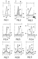
- the figure 1 is a cut of a skin at the location of a cut. More specifically, a skin 10 having an apparent face 12, having for example a grain, also has an inner face 14 to which a notch 16 opens by a opening 18. The notch has a V shape bounded by two sides 20 and 22.
- a plastic material intended to form a foam is introduced on the side of the inner face 14 of the skin 10.
- the opening 18 of the notch is relatively large, the fluid plastic material can easily penetrate virtually to the bottom of the notch.
- the interface between the foam 24, which is normally flexible, and the inner surface 14 of the skin has a bonding layer 26 which is substantially non-foamable and which constitutes a kind of continuous film in contact. substantially constant with the inner surface 14 of the skin.
- the plastic material that could penetrate the notch 16 before foaming forms a portion 28 which comprises only a few cavities and constitutes a kind of adhesive bridge over virtually the entire depth of the notch. While the foam has a low tear resistance due to its porosity, the plastic material with few cavities opposes on the contrary a high resistance to tearing.
- the plastic material does not penetrate the entire depth of the notch but only on the third or half, it forms a sufficiently strong bridge so that, after polymerization and cooling, the notch does not have a much lower resistance to that of the skin itself which surrounds it.
- the notch therefore no longer necessarily a preferential rupture device because of this connection between the two sides 20, 22 of the notch.
- the notch is given a configuration such that the bonding layer formed by the plastic material can not form between the two sides of the notch, a bridge of very small thickness and therefore low resistance.
- This bridge may be located near the inner face of the skin, at the opening, at the bottom of the notch, or in the intermediate position.
- the bridge formed by the tie layer is close to the inner surface of the skin.
- the bridge formed by the bonding layer is at the bottom of the notch.
- this bridge is in an intermediate position.
- FIGS. 3 to 6 represent embodiments in which the opening of the slot to the inner surface 14 is very small, so that the bonding layer 26 does not substantially penetrate the notch which remains empty.
- the notch is very thin so that its opening is very small, and it is inclined in a direction opposite to the flow direction 33 of the injected plastic to form the foam layer. In this way, the fluid plastic does not tend to penetrate the notch 32.
- the notch 34 has a bent shape so that it defines at the opening a shutter 36 which substantially closes the opening, so that the fluid plastic material forming the connecting layer 26 can not enter the notch.
- the notch 38 has a sinuous shape and a small opening, so that the fluid plastic material forming the bonding layer 26 stops at the opening. If locally the plastic material tended to penetrate the cut 38, the sinuous shape would reduce its penetration.
- the figure 6 represents an embodiment in which the notch 40 has, on the inner side side, a very small opening formed by a notch portion 42 which prevents the flowable plastic material from entering the tie layer 26.
- the notch By against, towards the inside of the skin, the notch has a wider portion 44 which can increase the breaking properties.
- FIGS. 11 and 12 illustrate the second form of the invention.
- the notch is open so widely that the fluid plastic material can penetrate to the bottom forming a thin bonding layer 26 on the walls of the notch.
- the width of the notch is such that the plastic material forms foam almost to the bottom of the notch. Consequently, the bridge formed between the two walls of the notch by the connecting layer 26 exists only at the bottom and has a small thickness. This bridge therefore has only a low breaking strength.
- the notch 76 is symmetrical, and in the embodiment of the figure 12 , the notch 80 is asymmetrical so that one side of the notch 80 is substantially perpendicular to the skin and the other is strongly inclined, for example at an angle of 45 °.
- the effect obtained during a break can thus be asymmetrical and promote the separation of the part to be torn off.
- FIGS 7 to 10 represent embodiments in which the two forms of the invention are combined. More specifically, the notches of these embodiments include, towards the inner surface 14, a broad portion giving the effect described with reference to the Figures 11 and 12 and, towards the bottom, a narrow part such that the opening has a small width which gives the phenomenon described with reference to the Figures 3 to 6 .
- the embodiment of the figure 7 has a notch 46 which has an outer portion 48 wide open, whose role is similar to that which has been described in reference to the figure 11 .
- the narrower inner portion of this notch portion 48 is connected by a narrow opening to a second notch portion 50 of small width.
- the bridge formed by the bonding layer is limited to a thin portion at the connection between the two portions 48 and 50 of the notch 46.
- the notch 60 has an outer portion 62 similar to that of the embodiment of the figure 8 , and an inner portion 64 which widens after a narrow opening, as in the embodiment of the figure 6 .
- the embodiment of the figure 10 is analogous to that of the figure 8 and has a notch 68 having a wide portion 70 on the side of the inner surface and a narrow portion 72 on the side of the exposed face.
- the notch portion 70 is distinguished by a bell-shaped shape which makes it possible to reduce the thickness of the bridge formed at the opening of the the internal groove portion 72, with respect to the embodiments of the Figures 7 to 9 .
- nick configurations they are not formed by pressing or molding, but by cutting using knives of suitable shape, preferably moved by a robot.
- the skin is placed on a strongly curved support 82, and a cut is made by a knife having a section of shape adapted to that of the notch widened on the shape.
- a knife having a section of shape adapted to that of the notch widened on the shape.
- the inner portion 44 of the notch is wider than the outer portion 42 in the use position ( figure 6 )
- the notch has a width which decreases constantly from the outside to the inside and which can thus be easily obtained with a robust cutting blade.
- the outer groove portion 42 is intended to form a substantially parallel-walled portion ( figure 6 ) whereas, in the embodiment of the figure 9 , the notch outer portion 66 is intended to delimit a widely open portion.
- the figure 13 represents in section, by way of example, a blade which can be used for the formation by cutting of the notch 80 shown in FIG. figure 12 .
- This cutting blade which only the tip cuts the skin, can be optionally heated and, in this case, it forms a bead as indicated by the reference 84 on the figure 12 .
Landscapes
- Engineering & Computer Science (AREA)
- Mechanical Engineering (AREA)
- Chemical & Material Sciences (AREA)
- Composite Materials (AREA)
- Air Bags (AREA)
- Vehicle Interior And Exterior Ornaments, Soundproofing, And Insulation (AREA)
- Mechanical Treatment Of Semiconductor (AREA)
- Bipolar Transistors (AREA)
- Adornments (AREA)
- Inorganic Compounds Of Heavy Metals (AREA)
- Piezo-Electric Or Mechanical Vibrators, Or Delay Or Filter Circuits (AREA)
- Finger-Pressure Massage (AREA)
- Casting Or Compression Moulding Of Plastics Or The Like (AREA)
- Laminated Bodies (AREA)
Description
- L'invention concerne une pièce d'habillage, essentiellement d'habillage intérieur d'automobile, ayant une face apparente formée d'une peau disposée sur une couche de mousse de matière plastique, ainsi qu'un appareil destiné à former les entailles dans la peau d'une pièce d'habillage et un procédé de fabrication d'une pièce d'habillage.
- On utilise de telles pièces d'habillage pour former un certain nombre de surfaces, et notamment des surfaces sous lesquelles sont cachés des sacs gonflables. Dans cette application, il est fréquent de délimiter, dans la peau de la pièce qui couvre le sac gonflable, une entaille qui délimite une partie destinée à se séparer, la peau se déchirant le long de l'entaille lorsque le sac gonflable fonctionne.
- On a constaté que, dans cette application, on observait un certain nombre de défauts de rupture suivant l'entaille. On a attribué ces défauts au fait que, lorsque la pièce d'habillage est formée par moussage d'une matière plastique au contact de la peau, la matière plastique pénètre dans l'entaille et forme un pont pratiquement continu sur au moins une partie importante de la profondeur de l'entaille. L'entaille perd donc sa fonctionnalité, puisque la liaison assurée par la matière plastique entre les deux côtés de l'entaille peut être plus robuste que celle que donnerait le matériau de la peau lui-même sans entaille.
- On a donc cherché à résoudre ce problème et on a ainsi proposé, dans le document
DE-298 21 409 qui divulgue une pièce d'habillage selon le préambule de la revendication 1, la fermeture de l'ouverture de l'entaille, du côté de la mousse, par application d'une "laque protectrice" destinée à former un pont sur l'entaille et à empêcher ainsi la matière plastique de la mousse de pénétrer dans l'entaille. - Ce procédé a l'inconvénient de nécessiter une opération spécifique de formation d'un pont sur l'ouverture de l'entaille, dans une opération particulière qui s'ajoute aux autres étapes de fabrication. En outre, la pièce obtenue doit avoir un pont de fermeture à la fois peu résistant pour ne pas gêner la déchirure de la peau lors du fonctionnement d'un sac gonflable, et suffisamment robuste pour résister aux différentes manipulations entre sa fabrication et l'opération de moussage à l'intérieur d'un moule.
- L'invention concerne la solution du problème précité d'une manière qui ne nécessite aucune opération supplémentaire de fabrication, et donc aucune augmentation de coût.
- Plus précisément, selon l'invention, on donne à l'entaille une configuration qui empêche la formation d'un pont d'épaisseur étendue entre les deux côtés de l'entaille. Dans une première forme, la configuration de l'entaille délimite une ouverture si étroite que, compte tenu des propriétés de mouillage et de tension superficielle de la peau et de la matière plastique utilisée pour la formation de la mousse, la matière plastique fluide ne pénètre pratiquement pas dans l'entaille. Dans une seconde forme, l'entaille est si largement ouverte que la matière plastique pénètre et c'est la mousse de matière plastique peu résistante qui remplit le volume de l'entaille et ne réduit pratiquement pas l'aptitude de l'entaille à former une zone de rupture préférentielle.
- Plus précisément, l'invention concerne une pièce d'habillage ayant une face apparente formée par une peau, la pièce étant du type qui comprend une peau disposée sur une mousse de matière plastique, la mousse étant liée à la peau par une couche continue de liaison formée spontanément à l'interface peau-mousse pendant l'opération de moussage de la matière plastique fluide au contact de la peau, la peau ayant un dispositif de rupture préférentielle comportant au moins une entaille qui débouche par une ouverture du côté opposé à la face apparente ; selon l'invention, dans toute la zone dans laquelle se trouve l'entaille pratiquement, la couche de liaison est au contact uniquement de la peau et de la mousse, et, au niveau de l'entaille et dans la direction de l'épaisseur de la peau, la couche de liaison est disposée sur l'ouverture avec une épaisseur très inférieure à la profondeur de l'entaille.
- Dans un premier mode de réalisation, l'ouverture de l'entaille à la face de la peau a une largeur au plus de l'ordre de grandeur de l'épaisseur de la couche de liaison. Dans ce cas, l'expression "de l'ordre de grandeur" indique une variation comprise entre 0,2 et 5 fois environ, la largeur de l'entaille restant toujours très inférieure à la profondeur de l'entaille.
- Dans un exemple, l'entaille a sa plus petite largeur pratiquement à l'ouverture ou à proximité de l'ouverture, afin que la matière plastique ne pénètre pratiquement pas dans l'entaille. Dans un autre exemple, un côté de l'ouverture de l'entaille porte un obturateur qui couvre l'ouverture. Dans un autre exemple, dans la partie voisine de l'ouverture, l'entaille a une largeur plus petite qu'à un emplacement plus éloigné de l'ouverture de l'entaille. Dans un autre exemple, l'entaille a une forme sinueuse en coupe transversale. Dans un autre exemple, l'entaille est inclinée en coupe transversale par rapport à la face opposée à la face apparente.
- Dans un second mode de réalisation, l'ouverture de l'entaille à la face de la peau est suffisamment large pour que la matière plastique pénètre et forme une mousse à l'intérieur de l'entaille, la couche de liaison suivant la surface interne de l'entaille jusqu'à un emplacement distant de la surface de la peau. Dans un exemple, à proximité de l'ouverture, l'entaille a, en coupe transversale, une forme en V d'angle supérieur à 45'.
- Dans un troisième mode de réalisation, qui combine les deux premiers, l'entaille comporte, depuis l'ouverture, une partie d'ouverture très large permettant la pénétration de la matière plastique, puis une partie plus profonde et étroite dans laquelle la matière plastique ne pénètre pratiquement pas.
- Dans un exemple, les bords de l'ouverture présentent une saillie.
- L'invention concerne aussi un appareil destiné à former les entailles dans la peau d'une pièce selon les paragraphes précédents, comprenant un bras de robot et une lame, dans lequel la lame a une section transversale adaptée à la section transversale d'une entaille à former, le bras de robot déplaçant la lame suivant une entaille à former. Dans un exemple, l'appareil comporte en outre une forme de support de la peau qui est localement arrondie à des emplacements prévus pour l'entaille.
- L'invention concerne aussi un procédé de fabrication d'une pièce d'habillage selon les paragraphes précédents, dans lequel une étape de fabrication de la peau comprend la disposition de la peau sur une forme ayant une saillie suivant le trajet voulu pour l'entaille, et la coupe de l'entaille par déplacement d'un couteau de section transversale adaptée à la section de l'entaille à réaliser, puis la séparation de la peau et de la forme.
- D'autres caractéristiques et avantages de l'invention seront mieux compris à la lecture de la description qui va suivre, faite en référence aux dessins annexés sur lesquels :
- la
figure 1 est une coupe d'une entaille formée dans une peau suivant le procédé classique ; - la
figure 2 est une coupe d'une partie d'une pièce d'habillage formée avec la peau représentée sur lafigure 1 et indiquant comment se pose le problème résolu par l'invention ; - les
figures 3, 4, 5 et 6 représentent quatre exemples de l'invention dans sa première forme de réalisation ; - les
figures 7, 8, 9 et10 représentent des entailles dans des exemples combinant deux formes de l'invention - les
figures 11 et 12 sont des coupes représentant des entailles dans d'autres exemples de l'invention correspondant à la seconde forme de réalisation de l'invention ; et - la
figure 13 représente un exemple de couteau utilisé pour la formation de l'entaille du mode de réalisation de lafigure 12 . - La
figure 1 est une coupe d'une peau à l'emplacement d'une entaille. Plus précisément, une peau 10 ayant une face apparente 12, présentant par exemple un grain, a aussi une face interne 14 à laquelle débouche une entaille 16 par une ouverture 18. L'entaille a une forme en V délimitée par deux côtés 20 et 22. - Lorsqu'une pièce d'habillage intérieur est fabriquée avec cette peau qui délimite un côté d'une cavité de moulage, une matière plastique destinée à former une mousse est introduite du côté de la face interne 14 de la peau 10. Comme l'ouverture 18 de l'entaille est relativement grande, la matière plastique fluide peut facilement pénétrer pratiquement jusqu'au fond de l'entaille. Lorsque le moussage est terminé, l'interface entre la mousse 24, qui est normalement souple, et la surface interne 14 de la peau comporte une couche de liaison 26 qui ne forme pratiquement pas de mousse et qui constitue une sorte de pellicule continue en contact pratiquement constant avec la surface interne 14 de la peau. Cependant, la matière plastique qui a pu pénétrer dans l'entaille 16 avant le moussage forme une partie 28 qui ne comprend que peu de cavités et constitue une sorte de pont adhésif sur pratiquement toute la profondeur de l'entaille. Alors que la mousse oppose une faible résistance à la déchirure à cause de sa porosité, la matière plastique avec peu de cavités oppose au contraire une grande résistance à la déchirure.
- Même si la matière plastique ne pénètre pas dans toute la profondeur de l'entaille mais seulement sur le tiers ou la moitié, elle forme un pont suffisamment résistant pour que, après polymérisation et refroidissement, l'entaille ne présente pas une résistance très inférieure à celle de la peau elle-même qui l'entoure. L'entaille ne constitue donc plus nécessairement un dispositif de rupture préférentielle à cause de cette liaison entre les deux côtés 20, 22 de l'entaille.
- La solution à ce problème est d'empêcher la matière plastique de moussage de pénétrer dans l'entaille, comme suggéré par le document précité de la technique antérieure.
- On peut envisager d'utiliser une fente très mince, mais il n'est pas facile de simplement réduire la largeur de l'entaille. En effet, celle-ci est normalement fabriquée par pression, et il n'est pas possible de réaliser des entailles de très faible largeur car les lames utilisées doivent être si minces qu'elles n'ont aucune durabilité.
- Selon l'invention, pour empêcher la matière plastique fluide de pénétrer dans l'entaille, on donne à l'entaille une configuration telle que la couche de liaison formée par la matière plastique ne peut former, entre les deux côtés de l'entaille, qu'un pont d'épaisseur très réduite et donc de faible résistance. Ce pont peut se trouver soit près de la face interne de la peau, au niveau de l'ouverture, soit au fond de l'entaille, soit en position intermédiaire.
- Dans les modes de réalisation des
figures 3, 4, 5 et 6 , le pont formé par la couche de liaison est à proximité de la surface interne de la peau. Dans les modes de réalisation desfigures 11 et 12 , le pont formé par la couche de liaison se trouve au fond de l'entaille. Dans les modes de réalisation desfigures 7, 8, 9 et10 , ce pont se trouve en position intermédiaire. - Les
figures 3 à 6 représentent des modes de réalisation dans lesquels l'ouverture de la fente à la surface interne 14 est très petite, de sorte que la couche de liaison 26 ne pénètre pratiquement pas dans l'entaille qui reste vide. - Dans le mode de réalisation de la
figure 3 , l'entaille est très fine de manière que son ouverture soit très petite, et elle est inclinée dans une direction opposée à la direction 33 d'écoulement de la matière plastique injectée pour former la couche de mousse. De cette manière, la matière plastique fluide n'a pas tendance à pénétrer dans l'entaille 32. - Dans le mode de réalisation de la
figure 4 , l'entaille 34 a une forme coudée afin qu'elle délimite au niveau de l'ouverture un obturateur 36 qui ferme pratiquement l'ouverture, de sorte que la matière plastique fluide formant la couche de liaison 26 ne peut pas pénétrer dans l'entaille. - Dans le mode de réalisation de la
figure 5 , l'entaille 38 a une forme sinueuse et une ouverture de petite dimension, si bien que la matière plastique fluide formant la couche de liaison 26 s'arrête à l'ouverture. Si localement la matière plastique tendait à pénétrer dans l'entaille 38, la forme sinueuse réduirait sa pénétration. - La
figure 6 représente un mode de réalisation dans lequel l'entaille 40 a, du côté de la face interne, une ouverture très petite formée par une partie d'entaille 42 qui empêche l'entrée de la matière plastique fluide de la couche de liaison 26. Par contre, vers l'intérieur de la peau, l'entaille a une partie plus large 44 qui peut accroître les propriétés de rupture. - Les
figures 11 et 12 illustrent la seconde forme de l'invention. Sur ces figures, l'entaille est ouverte si largement que la matière plastique fluide peut pénétrer jusqu'au fond en formant une mince couche de liaison 26 sur les parois de l'entaille. La largeur de l'entaille est telle que la matière plastique forme de la mousse presque jusqu'au fond de l'entaille. En conséquence, le pont formé entre les deux parois de l'entaille par la couche de liaison 26 n'existe qu'au fond et a une faible épaisseur. Ce pont ne présente donc qu'une faible résistance à la rupture. - Dans le mode de réalisation de la
figure 11 , l'entaille 76 est symétrique, et dans le mode de réalisation de lafigure 12 , l'entaille 80 est dissymétrique de sorte qu'un côté de l'entaille 80 est pratiquement perpendiculaire à la peau et l'autre est fortement inclinée, par exemple d'un angle de 45°. L'effet obtenu lors d'une rupture peut ainsi être asymétrique et favoriser la séparation de la partie qui doit être arrachée. - Les
figures 7 à 10 représentent des modes de réalisation dans lesquels les deux formes de l'invention sont combinées. Plus précisément, les entailles de ces modes de réalisation comportent, vers la surface interne 14, une partie large donnant l'effet décrit en référence auxfigures 11 et 12 , et, vers le fond, une partie étroite telle que l'ouverture a une faible largeur qui donne le phénomène décrit en référence auxfigures 3 à 6 . - Le mode de réalisation de la
figure 7 a une entaille 46 qui comporte une partie extérieure 48 largement ouverte, dont le rôle est analogue à celui qui a été décrit en référence à lafigure 11 . La partie interne la plus étroite de cette partie d'entaille 48 est reliée par une ouverture étroite à une seconde partie d'entaille 50 de faible largeur. Le pont formé par la couche de liaison se limite à une partie de faible épaisseur au niveau du raccord entre les deux parties 48 et 50 de l'entaille 46. - Dans le mode de réalisation de la
figure 8 , on a indiqué en outre la présence de saillies 58 autour de la partie extérieure d'entaille 54 qui est reliée à une partie intérieure étroite 56 dans l'entaille 52. Ces saillies 58 se forment lorsque l'outil utilisé pour former l'entaille est de type chauffant, si bien qu'un bourrelet tel que 58 (figure 8 ), 66 (figure 9 ), 74 (figure 10 ), 78 (figure 11 ) se forme autour de l'ouverture à la face interne. - Dans le mode de réalisation de la
figure 9 , l'entaille 60 a une partie extérieure 62 analogue à celle du mode de réalisation de lafigure 8 , et une partie intérieure 64 qui s'élargit après une ouverture étroite, comme dans le mode de réalisation de lafigure 6 . - Le mode de réalisation de la
figure 10 est analogue à celui de lafigure 8 et comporte une entaille 68 ayant une partie large 70 du côté de la surface interne et une partie étroite 72 du côté de la face apparente. Par rapport aux modes de réalisation desfigures 7 à 9 dans lesquels la partie d'entaille proche de la surface interne 14 a une forme en V en coupe transversale, la partie d'entaille 70 se distingue par une forme en cloche qui permet de réduire l'épaisseur du pont formé à l'ouverture de la partie interne 72 d'entaille, par rapport aux modes de réalisation desfigures 7 à 9 . - On a indiqué précédemment que la réalisation d'une fente très mince telle que représentée sur la
figure 3 ou ayant une partie localement très étroite comme indiqué sur lesfigures 6 et 9 posait des problèmes. En effet, la technique habituelle utilisée lors de la fabrication de la peau ne permet pas d'obtenir facilement de telles configurations, surtout parce que les outillages n'ont qu'une faible durabilité. - Selon l'invention, ce problème est résolu grâce à un procédé et un appareil spécifiques.
- Ainsi, dans un procédé de fabrication de telles configurations d'entailles, celles-ci ne sont pas formées par pression ou moulage, mais par découpe à l'aide de couteaux de forme adaptée, déplacés de préférence par un robot.
- Parmi les différents modes de réalisation d'entailles, ce sont les formes d'entailles des
figures 6 et 9 qui présentent le plus de difficultés de réalisation à cause de la variation de largeur de l'ouverture vers le fond. Lesfigures 6A et 9A sont des schémas indiquant comment sont formées ces entailles qui sont les plus difficiles à réaliser. - Comme l'indiquent les
figures 6A et 9A , à l'emplacement auquel doit être réalisée l'entaille, la peau est placée sur un support de forte courbure 82, et une découpe est réalisée par un couteau ayant une section de forme adaptée à celle de l'entaille élargie sur la forme. Ainsi, bien que la partie intérieure 44 de l'entaille soit plus large que la partie extérieure 42 en position d'utilisation (figure 6 ), on note sur lafigure 6A que, lors de la fabrication, l'entaille a une largeur qui diminue constamment de l'extérieur vers l'intérieur et qui peut donc être obtenue facilement avec une lame de coupe robuste. Sur lafigure 6A , la partie extérieure d'entaille 42 est destinée à former une partie à parois parallèles pratiquement (figure 6 ) alors que, dans le mode de réalisation de lafigure 9 , la partie extérieure d'entaille 66 est destinée à délimiter une partie largement ouverte. - La
figure 13 représente en coupe, à titre d'exemple, une lame qui peut être utilisée pour la formation par découpe de l'entaille 80 représentée sur lafigure 12 . Cette lame de coupe, dont seule la pointe entaille la peau, peut être éventuellement chauffée et, dans ce cas, elle forme un bourrelet tel qu'indiqué par la référence 84 sur lafigure 12 .
Claims (8)
- Pièce d'habillage ayant une face apparente (12) formée par une peau (10), la pièce étant du type qui comprend une peau (10) disposée sur une mousse (24) de matière plastique, la mousse (24) étant liée à la peau par une couche continue de liaison (26) formée spontanément à l'interface peau-mousse pendant l'opération de moussage de la matière plastique fluide au contact de la peau, la peau (10) ayant un dispositif de rupture préférentielle comportant au moins une entaille qui débouche par une ouverture du côté opposé à la face apparente (12), caractérisée en ce que, dans toute la zone dans laquelle se trouve l'entaille pratiquement, la couche de liaison (26) est au contact uniquement de la peau (10) et de la mousse (24), et, au niveau de l'entaille et dans la direction de l'épaisseur de la peau, la couche de liaison (26) est disposée sur l'ouverture avec une épaisseur très inférieure à la profondeur de l'entaille.
- Pièce d'habillage selon la revendication 1, caractérisée en ce que l'ouverture de l'entaille (32, 34, 38, 40) à la face de la peau a une largeur au plus de l'ordre de grandeur de l'épaisseur de la couche de liaison (26).
- Pièce d'habillage selon la revendication 2, caractérisée en ce que l'entaille (34, 38, 40) a sa plus petite largeur pratiquement à l'ouverture ou à proximité de l'ouverture, afin que la matière plastique fluide ne pénètre pratiquement pas dans l'entaille.
- Pièce d'habillage selon la revendication 2, caractérisée en ce que, dans la partie voisine de l'ouverture, l'entaille (40, 60) a une largeur plus petite qu'à un emplacement plus éloigné de l'ouverture de l'entaille.
- Pièce d'habillage selon la revendication 2, caractérisée en ce que l'entaille (38, 32) a une forme choisie parmi une forme sinueuse en coupe transversale, et une forme inclinée en coupe transversale par rapport à la face opposée à la face apparente.
- Pièce d'habillage selon la revendication 1, caractérisée en ce que l'ouverture de l'entaille (76, 80) à la face de la peau est suffisamment large pour que la matière plastique pénètre et forme une mousse à l'intérieur de l'entaille (76, 80), la couche de liaison (26) suivant la surface interne de l'entaille (76, 80) jusqu'à un emplacement distant de la surface de la peau.
- Pièce d'habillage selon la revendication 1, caractérisée en ce que l'entaille (46, 52, 60, 68) comporte, depuis l'ouverture, une partie d'ouverture très large permettant la pénétration de la matière plastique, puis une partie plus profonde et étroite dans laquelle la matière plastique ne pénètre pratiquement pas.
- Pièce d'habillage selon l'une quelconque des revendications précédentes, caractérisée en ce que les bords de l'ouverture présentent une saillie (58, 66, 74, 78, 84).
Priority Applications (1)
| Application Number | Priority Date | Filing Date | Title |
|---|---|---|---|
| PL06841848T PL1957322T3 (pl) | 2005-12-06 | 2006-12-04 | Element wykładzinowy |
Applications Claiming Priority (2)
| Application Number | Priority Date | Filing Date | Title |
|---|---|---|---|
| FR0512363A FR2894209B1 (fr) | 2005-12-06 | 2005-12-06 | Piece d'habillage, appareil de formation d'entailles, et procede de fabrication d'une piece d'habillage |
| PCT/FR2006/002639 WO2007065990A1 (fr) | 2005-12-06 | 2006-12-04 | Piece d'habillage |
Publications (2)
| Publication Number | Publication Date |
|---|---|
| EP1957322A1 EP1957322A1 (fr) | 2008-08-20 |
| EP1957322B1 true EP1957322B1 (fr) | 2009-07-08 |
Family
ID=36579319
Family Applications (1)
| Application Number | Title | Priority Date | Filing Date |
|---|---|---|---|
| EP20060841848 Active EP1957322B1 (fr) | 2005-12-06 | 2006-12-04 | Piece d'habillage |
Country Status (7)
| Country | Link |
|---|---|
| US (2) | US8337981B2 (fr) |
| EP (1) | EP1957322B1 (fr) |
| AT (1) | ATE435788T1 (fr) |
| DE (1) | DE602006007732D1 (fr) |
| FR (1) | FR2894209B1 (fr) |
| PL (1) | PL1957322T3 (fr) |
| WO (1) | WO2007065990A1 (fr) |
Families Citing this family (2)
| Publication number | Priority date | Publication date | Assignee | Title |
|---|---|---|---|---|
| FR2894209B1 (fr) * | 2005-12-06 | 2009-11-06 | Faurecia Interieur Ind Snc | Piece d'habillage, appareil de formation d'entailles, et procede de fabrication d'une piece d'habillage |
| FR2979307B1 (fr) * | 2011-08-23 | 2013-10-04 | Faurecia Interieur Ind | Habillage de vehicule comprenant une armature, un garnissage et un element de decor |
Family Cites Families (5)
| Publication number | Priority date | Publication date | Assignee | Title |
|---|---|---|---|---|
| JP3011888B2 (ja) * | 1996-07-19 | 2000-02-21 | 株式会社イノアックコーポレーション | インストルメントパネルのエアバッグドアの構造 |
| DE29821409U1 (de) * | 1998-11-25 | 1999-03-18 | Sommer-Allibert-Lignotock GmbH, 76744 Wörth | Innenverkleidungsteil für Kraftfahrzeuge |
| DE29917856U1 (de) * | 1999-09-30 | 1999-12-16 | SAI Automotive SAL GmbH, 76744 Wörth | Dekorationsfolie mit eingebrachter Reißnaht |
| US6533314B2 (en) * | 1999-12-30 | 2003-03-18 | Delphi Technologies, Inc. | Instrument panel with integral hidden door cover and method of manufacture thereof |
| FR2894209B1 (fr) * | 2005-12-06 | 2009-11-06 | Faurecia Interieur Ind Snc | Piece d'habillage, appareil de formation d'entailles, et procede de fabrication d'une piece d'habillage |
-
2005
- 2005-12-06 FR FR0512363A patent/FR2894209B1/fr not_active Expired - Fee Related
-
2006
- 2006-12-04 WO PCT/FR2006/002639 patent/WO2007065990A1/fr not_active Ceased
- 2006-12-04 PL PL06841848T patent/PL1957322T3/pl unknown
- 2006-12-04 EP EP20060841848 patent/EP1957322B1/fr active Active
- 2006-12-04 US US12/096,434 patent/US8337981B2/en not_active Expired - Fee Related
- 2006-12-04 DE DE200660007732 patent/DE602006007732D1/de active Active
- 2006-12-04 AT AT06841848T patent/ATE435788T1/de not_active IP Right Cessation
-
2012
- 2012-11-07 US US13/671,008 patent/US8852735B2/en active Active
Also Published As
| Publication number | Publication date |
|---|---|
| PL1957322T3 (pl) | 2010-01-29 |
| US20090252930A1 (en) | 2009-10-08 |
| WO2007065990A1 (fr) | 2007-06-14 |
| US8337981B2 (en) | 2012-12-25 |
| DE602006007732D1 (de) | 2009-08-20 |
| US8852735B2 (en) | 2014-10-07 |
| EP1957322A1 (fr) | 2008-08-20 |
| US20130091799A1 (en) | 2013-04-18 |
| ATE435788T1 (de) | 2009-07-15 |
| FR2894209A1 (fr) | 2007-06-08 |
| FR2894209B1 (fr) | 2009-11-06 |
Similar Documents
| Publication | Publication Date | Title |
|---|---|---|
| EP0894046B1 (fr) | Procede pour realiser une piece finie comprenant une zone destinee a permettre la creation d'un passage, piece finie et ensemble correspondant | |
| EP2782840B1 (fr) | Dispositif de fermeture pour sachets à effet tactile et sonore et sachet comprenant un tel dispositif | |
| EP1580077B1 (fr) | Elément d'habillage, notamment pour intérieur d'automobile, et son procédé de fabrication | |
| EP2674334B1 (fr) | Dispositif d'obturation d'un module de coussin gonflable comprenant une zone formant charnière de longueur variable | |
| LU84319A1 (fr) | Procede de finition de produits en resine armee,en particulier des casques,et produits fabriques par ce procede | |
| FR2683190A1 (fr) | Profile pour pare-brise et son procede de fabrication. | |
| FR2627162A1 (fr) | Fermeture de fond moulee pour emballage a lignes d'affaiblissement permettant une attaque de coulee unique | |
| EP1094013A1 (fr) | Film pour fabriquer un emballage ayent prédécoupe avec une tendance à délamination | |
| FR2894209A1 (fr) | Piece d'habillage, appareil de formation d'entailles, et procede de fabrication d'une piece d'habillage | |
| EP2812169B1 (fr) | Procédé de réalisation d'un ensemble plan-vasque et ensemble plan-vasque obtenu par ce procédé | |
| WO2018002502A1 (fr) | Procede de moulage d'un cordon profile affleurant sur un element vitre et dispositif de moulage pour ce procede | |
| WO2008012436A2 (fr) | Planche de bord à sac gonflable, et son procédé de fabrication | |
| CA2599845C (fr) | Procede de moulage d'un boyau profile sur un vitrage | |
| EP3221114B1 (fr) | Procede de fabrication d'une piece de véhicule en materiau polymere | |
| EP2055877A1 (fr) | Procédé de collage d'une pièce de montage sur une surface | |
| WO2008117196A1 (fr) | Zone de dechirure orientee pour film en plastique | |
| FR2771718A1 (fr) | Conditionnement, notamment sachet, a ouverture facilitee, procede de fabrication et installation pour la mise en oeuvre dudit procede | |
| FR2798894A1 (fr) | Piece thermoplastique de masquage d'un coussin gonflable de securite | |
| FR2706351A1 (fr) | Vitrage surmoulé et dispositif pour obtenir ce vitrage. | |
| FR2884786A1 (fr) | Porte de tableau de bord | |
| EP3826818B1 (fr) | Procede de fabrication d'un ensemble d'elements de garniture montrant un revetement decoratif | |
| FR2969029A1 (fr) | Agencement de deux pieces en materiaux thermoplastiques destinees a etre assemblees par soudage laser | |
| EP0724942A1 (fr) | Procédé de réalisation de pièces composites en matière plastique comportant un revêtement de surface, moules pour sa mise en oeuvre et pièces composites ainsi obtenues | |
| EP1757666B1 (fr) | Procédé de solidarisation de deux pièces en matière thermoplastique au moyen d'une matière liante | |
| FR2987775A1 (fr) | Procede de fabrication d'un article comprenant un element en mousse |
Legal Events
| Date | Code | Title | Description |
|---|---|---|---|
| PUAI | Public reference made under article 153(3) epc to a published international application that has entered the european phase |
Free format text: ORIGINAL CODE: 0009012 |
|
| 17P | Request for examination filed |
Effective date: 20080606 |
|
| AK | Designated contracting states |
Kind code of ref document: A1 Designated state(s): AT BE BG CH CY CZ DE DK EE ES FI FR GB GR HU IE IS IT LI LT LU LV MC NL PL PT RO SE SI SK TR |
|
| GRAP | Despatch of communication of intention to grant a patent |
Free format text: ORIGINAL CODE: EPIDOSNIGR1 |
|
| DAX | Request for extension of the european patent (deleted) | ||
| GRAS | Grant fee paid |
Free format text: ORIGINAL CODE: EPIDOSNIGR3 |
|
| GRAA | (expected) grant |
Free format text: ORIGINAL CODE: 0009210 |
|
| AK | Designated contracting states |
Kind code of ref document: B1 Designated state(s): AT BE BG CH CY CZ DE DK EE ES FI FR GB GR HU IE IS IT LI LT LU LV MC NL PL PT RO SE SI SK TR |
|
| REG | Reference to a national code |
Ref country code: GB Ref legal event code: FG4D Free format text: NOT ENGLISH |
|
| REG | Reference to a national code |
Ref country code: CH Ref legal event code: EP |
|
| REG | Reference to a national code |
Ref country code: IE Ref legal event code: FG4D |
|
| REF | Corresponds to: |
Ref document number: 602006007732 Country of ref document: DE Date of ref document: 20090820 Kind code of ref document: P |
|
| PG25 | Lapsed in a contracting state [announced via postgrant information from national office to epo] |
Ref country code: SI Free format text: LAPSE BECAUSE OF FAILURE TO SUBMIT A TRANSLATION OF THE DESCRIPTION OR TO PAY THE FEE WITHIN THE PRESCRIBED TIME-LIMIT Effective date: 20090708 |
|
| NLV1 | Nl: lapsed or annulled due to failure to fulfill the requirements of art. 29p and 29m of the patents act | ||
| REG | Reference to a national code |
Ref country code: SK Ref legal event code: T3 Ref document number: E 6108 Country of ref document: SK |
|
| PG25 | Lapsed in a contracting state [announced via postgrant information from national office to epo] |
Ref country code: IS Free format text: LAPSE BECAUSE OF FAILURE TO SUBMIT A TRANSLATION OF THE DESCRIPTION OR TO PAY THE FEE WITHIN THE PRESCRIBED TIME-LIMIT Effective date: 20091108 Ref country code: FI Free format text: LAPSE BECAUSE OF FAILURE TO SUBMIT A TRANSLATION OF THE DESCRIPTION OR TO PAY THE FEE WITHIN THE PRESCRIBED TIME-LIMIT Effective date: 20090708 Ref country code: LT Free format text: LAPSE BECAUSE OF FAILURE TO SUBMIT A TRANSLATION OF THE DESCRIPTION OR TO PAY THE FEE WITHIN THE PRESCRIBED TIME-LIMIT Effective date: 20090708 Ref country code: ES Free format text: LAPSE BECAUSE OF FAILURE TO SUBMIT A TRANSLATION OF THE DESCRIPTION OR TO PAY THE FEE WITHIN THE PRESCRIBED TIME-LIMIT Effective date: 20091019 Ref country code: AT Free format text: LAPSE BECAUSE OF FAILURE TO SUBMIT A TRANSLATION OF THE DESCRIPTION OR TO PAY THE FEE WITHIN THE PRESCRIBED TIME-LIMIT Effective date: 20090708 |
|
| REG | Reference to a national code |
Ref country code: PL Ref legal event code: T3 |
|
| REG | Reference to a national code |
Ref country code: IE Ref legal event code: FD4D |
|
| PG25 | Lapsed in a contracting state [announced via postgrant information from national office to epo] |
Ref country code: LV Free format text: LAPSE BECAUSE OF FAILURE TO SUBMIT A TRANSLATION OF THE DESCRIPTION OR TO PAY THE FEE WITHIN THE PRESCRIBED TIME-LIMIT Effective date: 20090708 Ref country code: NL Free format text: LAPSE BECAUSE OF FAILURE TO SUBMIT A TRANSLATION OF THE DESCRIPTION OR TO PAY THE FEE WITHIN THE PRESCRIBED TIME-LIMIT Effective date: 20090708 |
|
| PG25 | Lapsed in a contracting state [announced via postgrant information from national office to epo] |
Ref country code: BG Free format text: LAPSE BECAUSE OF FAILURE TO SUBMIT A TRANSLATION OF THE DESCRIPTION OR TO PAY THE FEE WITHIN THE PRESCRIBED TIME-LIMIT Effective date: 20091008 Ref country code: PT Free format text: LAPSE BECAUSE OF FAILURE TO SUBMIT A TRANSLATION OF THE DESCRIPTION OR TO PAY THE FEE WITHIN THE PRESCRIBED TIME-LIMIT Effective date: 20091109 |
|
| PG25 | Lapsed in a contracting state [announced via postgrant information from national office to epo] |
Ref country code: IE Free format text: LAPSE BECAUSE OF FAILURE TO SUBMIT A TRANSLATION OF THE DESCRIPTION OR TO PAY THE FEE WITHIN THE PRESCRIBED TIME-LIMIT Effective date: 20090708 Ref country code: RO Free format text: LAPSE BECAUSE OF FAILURE TO SUBMIT A TRANSLATION OF THE DESCRIPTION OR TO PAY THE FEE WITHIN THE PRESCRIBED TIME-LIMIT Effective date: 20090708 Ref country code: DK Free format text: LAPSE BECAUSE OF FAILURE TO SUBMIT A TRANSLATION OF THE DESCRIPTION OR TO PAY THE FEE WITHIN THE PRESCRIBED TIME-LIMIT Effective date: 20090708 Ref country code: EE Free format text: LAPSE BECAUSE OF FAILURE TO SUBMIT A TRANSLATION OF THE DESCRIPTION OR TO PAY THE FEE WITHIN THE PRESCRIBED TIME-LIMIT Effective date: 20090708 |
|
| PLBE | No opposition filed within time limit |
Free format text: ORIGINAL CODE: 0009261 |
|
| STAA | Information on the status of an ep patent application or granted ep patent |
Free format text: STATUS: NO OPPOSITION FILED WITHIN TIME LIMIT |
|
| 26N | No opposition filed |
Effective date: 20100409 |
|
| BERE | Be: lapsed |
Owner name: FAURECIA INTERIEUR INDUSTRIE Effective date: 20091231 |
|
| PG25 | Lapsed in a contracting state [announced via postgrant information from national office to epo] |
Ref country code: MC Free format text: LAPSE BECAUSE OF NON-PAYMENT OF DUE FEES Effective date: 20100701 |
|
| PG25 | Lapsed in a contracting state [announced via postgrant information from national office to epo] |
Ref country code: BE Free format text: LAPSE BECAUSE OF NON-PAYMENT OF DUE FEES Effective date: 20091231 Ref country code: GR Free format text: LAPSE BECAUSE OF FAILURE TO SUBMIT A TRANSLATION OF THE DESCRIPTION OR TO PAY THE FEE WITHIN THE PRESCRIBED TIME-LIMIT Effective date: 20091009 |
|
| PG25 | Lapsed in a contracting state [announced via postgrant information from national office to epo] |
Ref country code: IT Free format text: LAPSE BECAUSE OF FAILURE TO SUBMIT A TRANSLATION OF THE DESCRIPTION OR TO PAY THE FEE WITHIN THE PRESCRIBED TIME-LIMIT Effective date: 20090708 |
|
| PG25 | Lapsed in a contracting state [announced via postgrant information from national office to epo] |
Ref country code: LU Free format text: LAPSE BECAUSE OF NON-PAYMENT OF DUE FEES Effective date: 20091204 |
|
| PG25 | Lapsed in a contracting state [announced via postgrant information from national office to epo] |
Ref country code: HU Free format text: LAPSE BECAUSE OF FAILURE TO SUBMIT A TRANSLATION OF THE DESCRIPTION OR TO PAY THE FEE WITHIN THE PRESCRIBED TIME-LIMIT Effective date: 20100109 |
|
| REG | Reference to a national code |
Ref country code: CH Ref legal event code: PL |
|
| PG25 | Lapsed in a contracting state [announced via postgrant information from national office to epo] |
Ref country code: TR Free format text: LAPSE BECAUSE OF FAILURE TO SUBMIT A TRANSLATION OF THE DESCRIPTION OR TO PAY THE FEE WITHIN THE PRESCRIBED TIME-LIMIT Effective date: 20090708 |
|
| PG25 | Lapsed in a contracting state [announced via postgrant information from national office to epo] |
Ref country code: CY Free format text: LAPSE BECAUSE OF FAILURE TO SUBMIT A TRANSLATION OF THE DESCRIPTION OR TO PAY THE FEE WITHIN THE PRESCRIBED TIME-LIMIT Effective date: 20090708 |
|
| PG25 | Lapsed in a contracting state [announced via postgrant information from national office to epo] |
Ref country code: LI Free format text: LAPSE BECAUSE OF NON-PAYMENT OF DUE FEES Effective date: 20101231 Ref country code: CH Free format text: LAPSE BECAUSE OF NON-PAYMENT OF DUE FEES Effective date: 20101231 |
|
| PG25 | Lapsed in a contracting state [announced via postgrant information from national office to epo] |
Ref country code: SE Free format text: LAPSE BECAUSE OF FAILURE TO SUBMIT A TRANSLATION OF THE DESCRIPTION OR TO PAY THE FEE WITHIN THE PRESCRIBED TIME-LIMIT Effective date: 20090708 |
|
| REG | Reference to a national code |
Ref country code: FR Ref legal event code: PLFP Year of fee payment: 10 |
|
| REG | Reference to a national code |
Ref country code: FR Ref legal event code: PLFP Year of fee payment: 11 |
|
| REG | Reference to a national code |
Ref country code: FR Ref legal event code: PLFP Year of fee payment: 12 |
|
| PGFP | Annual fee paid to national office [announced via postgrant information from national office to epo] |
Ref country code: GB Payment date: 20221116 Year of fee payment: 17 Ref country code: DE Payment date: 20221122 Year of fee payment: 17 |
|
| PGFP | Annual fee paid to national office [announced via postgrant information from national office to epo] |
Ref country code: SK Payment date: 20231128 Year of fee payment: 18 |
|
| PGFP | Annual fee paid to national office [announced via postgrant information from national office to epo] |
Ref country code: FR Payment date: 20231122 Year of fee payment: 18 Ref country code: CZ Payment date: 20231124 Year of fee payment: 18 |
|
| PGFP | Annual fee paid to national office [announced via postgrant information from national office to epo] |
Ref country code: PL Payment date: 20231127 Year of fee payment: 18 |
|
| REG | Reference to a national code |
Ref country code: DE Ref legal event code: R119 Ref document number: 602006007732 Country of ref document: DE |
|
| GBPC | Gb: european patent ceased through non-payment of renewal fee |
Effective date: 20231204 |
|
| PG25 | Lapsed in a contracting state [announced via postgrant information from national office to epo] |
Ref country code: DE Free format text: LAPSE BECAUSE OF NON-PAYMENT OF DUE FEES Effective date: 20240702 |
|
| PG25 | Lapsed in a contracting state [announced via postgrant information from national office to epo] |
Ref country code: GB Free format text: LAPSE BECAUSE OF NON-PAYMENT OF DUE FEES Effective date: 20231204 |
|
| PG25 | Lapsed in a contracting state [announced via postgrant information from national office to epo] |
Ref country code: GB Free format text: LAPSE BECAUSE OF NON-PAYMENT OF DUE FEES Effective date: 20231204 Ref country code: DE Free format text: LAPSE BECAUSE OF NON-PAYMENT OF DUE FEES Effective date: 20240702 |
|
| REG | Reference to a national code |
Ref country code: SK Ref legal event code: MM4A Ref document number: E 6108 Country of ref document: SK Effective date: 20241204 |
|
| PG25 | Lapsed in a contracting state [announced via postgrant information from national office to epo] |
Ref country code: CZ Free format text: LAPSE BECAUSE OF NON-PAYMENT OF DUE FEES Effective date: 20241204 |
|
| PG25 | Lapsed in a contracting state [announced via postgrant information from national office to epo] |
Ref country code: FR Free format text: LAPSE BECAUSE OF NON-PAYMENT OF DUE FEES Effective date: 20241231 |
|
| PG25 | Lapsed in a contracting state [announced via postgrant information from national office to epo] |
Ref country code: SK Free format text: LAPSE BECAUSE OF NON-PAYMENT OF DUE FEES Effective date: 20241204 |