EP1957180B1 - Porous cordierite ceramic honeycomb article with improved strength - Google Patents
Porous cordierite ceramic honeycomb article with improved strength Download PDFInfo
- Publication number
- EP1957180B1 EP1957180B1 EP06844406.6A EP06844406A EP1957180B1 EP 1957180 B1 EP1957180 B1 EP 1957180B1 EP 06844406 A EP06844406 A EP 06844406A EP 1957180 B1 EP1957180 B1 EP 1957180B1
- Authority
- EP
- European Patent Office
- Prior art keywords
- cte
- tpv
- honeycomb article
- porosity
- ceramic honeycomb
- Prior art date
- Legal status (The legal status is an assumption and is not a legal conclusion. Google has not performed a legal analysis and makes no representation as to the accuracy of the status listed.)
- Active
Links
- 229910052878 cordierite Inorganic materials 0.000 title claims description 59
- JSKIRARMQDRGJZ-UHFFFAOYSA-N dimagnesium dioxido-bis[(1-oxido-3-oxo-2,4,6,8,9-pentaoxa-1,3-disila-5,7-dialuminabicyclo[3.3.1]nonan-7-yl)oxy]silane Chemical compound [Mg++].[Mg++].[O-][Si]([O-])(O[Al]1O[Al]2O[Si](=O)O[Si]([O-])(O1)O2)O[Al]1O[Al]2O[Si](=O)O[Si]([O-])(O1)O2 JSKIRARMQDRGJZ-UHFFFAOYSA-N 0.000 title claims description 59
- 239000000919 ceramic Substances 0.000 title claims description 27
- 239000011148 porous material Substances 0.000 claims description 54
- 239000013078 crystal Substances 0.000 claims description 13
- QSHDDOUJBYECFT-UHFFFAOYSA-N mercury Chemical compound [Hg] QSHDDOUJBYECFT-UHFFFAOYSA-N 0.000 claims description 10
- 229910052753 mercury Inorganic materials 0.000 claims description 10
- 238000002441 X-ray diffraction Methods 0.000 claims description 8
- 230000001186 cumulative effect Effects 0.000 claims description 4
- 241000264877 Hippospongia communis Species 0.000 description 81
- 239000005995 Aluminium silicate Substances 0.000 description 73
- 235000012211 aluminium silicate Nutrition 0.000 description 73
- NLYAJNPCOHFWQQ-UHFFFAOYSA-N kaolin Chemical compound O.O.O=[Al]O[Si](=O)O[Si](=O)O[Al]=O NLYAJNPCOHFWQQ-UHFFFAOYSA-N 0.000 description 71
- 238000010438 heat treatment Methods 0.000 description 68
- 239000000454 talc Substances 0.000 description 49
- 229910052623 talc Inorganic materials 0.000 description 49
- 239000002245 particle Substances 0.000 description 36
- 239000002994 raw material Substances 0.000 description 32
- 230000000052 comparative effect Effects 0.000 description 25
- 230000035939 shock Effects 0.000 description 25
- OKTJSMMVPCPJKN-UHFFFAOYSA-N Carbon Chemical compound [C] OKTJSMMVPCPJKN-UHFFFAOYSA-N 0.000 description 24
- PNEYBMLMFCGWSK-UHFFFAOYSA-N aluminium oxide Inorganic materials [O-2].[O-2].[O-2].[Al+3].[Al+3] PNEYBMLMFCGWSK-UHFFFAOYSA-N 0.000 description 24
- 239000004071 soot Substances 0.000 description 24
- 229910001679 gibbsite Inorganic materials 0.000 description 21
- 239000000203 mixture Substances 0.000 description 21
- VYPSYNLAJGMNEJ-UHFFFAOYSA-N Silicium dioxide Chemical compound O=[Si]=O VYPSYNLAJGMNEJ-UHFFFAOYSA-N 0.000 description 20
- 229910021502 aluminium hydroxide Inorganic materials 0.000 description 20
- 239000010439 graphite Substances 0.000 description 20
- 229910002804 graphite Inorganic materials 0.000 description 20
- 230000001413 cellular effect Effects 0.000 description 18
- WNROFYMDJYEPJX-UHFFFAOYSA-K aluminium hydroxide Chemical compound [OH-].[OH-].[OH-].[Al+3] WNROFYMDJYEPJX-UHFFFAOYSA-K 0.000 description 16
- 229910052596 spinel Inorganic materials 0.000 description 13
- 239000011029 spinel Substances 0.000 description 13
- KZHJGOXRZJKJNY-UHFFFAOYSA-N dioxosilane;oxo(oxoalumanyloxy)alumane Chemical compound O=[Si]=O.O=[Si]=O.O=[Al]O[Al]=O.O=[Al]O[Al]=O.O=[Al]O[Al]=O KZHJGOXRZJKJNY-UHFFFAOYSA-N 0.000 description 12
- 238000009826 distribution Methods 0.000 description 12
- 229910052863 mullite Inorganic materials 0.000 description 12
- 229910052799 carbon Inorganic materials 0.000 description 11
- 239000007789 gas Substances 0.000 description 10
- 238000000034 method Methods 0.000 description 9
- 239000000463 material Substances 0.000 description 8
- 229910001593 boehmite Inorganic materials 0.000 description 7
- 230000008929 regeneration Effects 0.000 description 7
- 238000011069 regeneration method Methods 0.000 description 7
- 239000000377 silicon dioxide Substances 0.000 description 7
- FAHBNUUHRFUEAI-UHFFFAOYSA-M hydroxidooxidoaluminium Chemical compound O[Al]=O FAHBNUUHRFUEAI-UHFFFAOYSA-M 0.000 description 6
- 238000004519 manufacturing process Methods 0.000 description 6
- 239000003795 chemical substances by application Substances 0.000 description 5
- 238000005336 cracking Methods 0.000 description 5
- 238000001914 filtration Methods 0.000 description 5
- 238000010304 firing Methods 0.000 description 5
- 239000004033 plastic Substances 0.000 description 5
- 229920003023 plastic Polymers 0.000 description 5
- 229920001592 potato starch Polymers 0.000 description 5
- XLYOFNOQVPJJNP-UHFFFAOYSA-N water Chemical compound O XLYOFNOQVPJJNP-UHFFFAOYSA-N 0.000 description 5
- 239000011230 binding agent Substances 0.000 description 4
- -1 fused silica Chemical compound 0.000 description 4
- 238000011068 loading method Methods 0.000 description 4
- 238000002156 mixing Methods 0.000 description 4
- XEEYBQQBJWHFJM-UHFFFAOYSA-N Iron Chemical compound [Fe] XEEYBQQBJWHFJM-UHFFFAOYSA-N 0.000 description 3
- KFZMGEQAYNKOFK-UHFFFAOYSA-N Isopropanol Chemical compound CC(C)O KFZMGEQAYNKOFK-UHFFFAOYSA-N 0.000 description 3
- 239000006057 Non-nutritive feed additive Substances 0.000 description 3
- KDLHZDBZIXYQEI-UHFFFAOYSA-N Palladium Chemical compound [Pd] KDLHZDBZIXYQEI-UHFFFAOYSA-N 0.000 description 3
- 239000004698 Polyethylene Substances 0.000 description 3
- 241000276425 Xiphophorus maculatus Species 0.000 description 3
- 239000011324 bead Substances 0.000 description 3
- 239000003054 catalyst Substances 0.000 description 3
- 230000003197 catalytic effect Effects 0.000 description 3
- 238000007571 dilatometry Methods 0.000 description 3
- 238000001125 extrusion Methods 0.000 description 3
- 239000000314 lubricant Substances 0.000 description 3
- 229910052751 metal Inorganic materials 0.000 description 3
- 239000002184 metal Substances 0.000 description 3
- 229920000609 methyl cellulose Polymers 0.000 description 3
- 239000001923 methylcellulose Substances 0.000 description 3
- BASFCYQUMIYNBI-UHFFFAOYSA-N platinum Chemical compound [Pt] BASFCYQUMIYNBI-UHFFFAOYSA-N 0.000 description 3
- 229920000573 polyethylene Polymers 0.000 description 3
- 238000002459 porosimetry Methods 0.000 description 3
- 239000000843 powder Substances 0.000 description 3
- 235000012239 silicon dioxide Nutrition 0.000 description 3
- RYYKJJJTJZKILX-UHFFFAOYSA-M sodium octadecanoate Chemical compound [Na+].CCCCCCCCCCCCCCCCCC([O-])=O RYYKJJJTJZKILX-UHFFFAOYSA-M 0.000 description 3
- 239000000758 substrate Substances 0.000 description 3
- 238000005382 thermal cycling Methods 0.000 description 3
- CURLTUGMZLYLDI-UHFFFAOYSA-N Carbon dioxide Chemical compound O=C=O CURLTUGMZLYLDI-UHFFFAOYSA-N 0.000 description 2
- 230000009286 beneficial effect Effects 0.000 description 2
- 239000011248 coating agent Substances 0.000 description 2
- 238000000576 coating method Methods 0.000 description 2
- 239000010949 copper Substances 0.000 description 2
- 229910052593 corundum Inorganic materials 0.000 description 2
- 239000000446 fuel Substances 0.000 description 2
- 239000005350 fused silica glass Substances 0.000 description 2
- 229910010272 inorganic material Inorganic materials 0.000 description 2
- 239000011147 inorganic material Substances 0.000 description 2
- 239000007788 liquid Substances 0.000 description 2
- 239000010453 quartz Substances 0.000 description 2
- 230000005855 radiation Effects 0.000 description 2
- 239000007787 solid Substances 0.000 description 2
- 238000010345 tape casting Methods 0.000 description 2
- 230000008646 thermal stress Effects 0.000 description 2
- UGFAIRIUMAVXCW-UHFFFAOYSA-N Carbon monoxide Chemical compound [O+]#[C-] UGFAIRIUMAVXCW-UHFFFAOYSA-N 0.000 description 1
- 229910052684 Cerium Inorganic materials 0.000 description 1
- RYGMFSIKBFXOCR-UHFFFAOYSA-N Copper Chemical compound [Cu] RYGMFSIKBFXOCR-UHFFFAOYSA-N 0.000 description 1
- 208000003629 Rupture Diseases 0.000 description 1
- SNAAJJQQZSMGQD-UHFFFAOYSA-N aluminum magnesium Chemical compound [Mg].[Al] SNAAJJQQZSMGQD-UHFFFAOYSA-N 0.000 description 1
- 230000006399 behavior Effects 0.000 description 1
- 230000015572 biosynthetic process Effects 0.000 description 1
- 238000003490 calendering Methods 0.000 description 1
- 238000009924 canning Methods 0.000 description 1
- 229910002092 carbon dioxide Inorganic materials 0.000 description 1
- 239000001569 carbon dioxide Substances 0.000 description 1
- 229910002091 carbon monoxide Inorganic materials 0.000 description 1
- 239000001913 cellulose Substances 0.000 description 1
- 229920002678 cellulose Polymers 0.000 description 1
- GWXLDORMOJMVQZ-UHFFFAOYSA-N cerium Chemical compound [Ce] GWXLDORMOJMVQZ-UHFFFAOYSA-N 0.000 description 1
- 238000002485 combustion reaction Methods 0.000 description 1
- 150000001875 compounds Chemical class 0.000 description 1
- 230000006835 compression Effects 0.000 description 1
- 238000007906 compression Methods 0.000 description 1
- 229910052802 copper Inorganic materials 0.000 description 1
- 239000010431 corundum Substances 0.000 description 1
- 229910052906 cristobalite Inorganic materials 0.000 description 1
- 229910002026 crystalline silica Inorganic materials 0.000 description 1
- 239000004148 curcumin Substances 0.000 description 1
- 230000003247 decreasing effect Effects 0.000 description 1
- 238000010586 diagram Methods 0.000 description 1
- 229910001648 diaspore Inorganic materials 0.000 description 1
- FPAFDBFIGPHWGO-UHFFFAOYSA-N dioxosilane;oxomagnesium;hydrate Chemical compound O.[Mg]=O.[Mg]=O.[Mg]=O.O=[Si]=O.O=[Si]=O.O=[Si]=O.O=[Si]=O FPAFDBFIGPHWGO-UHFFFAOYSA-N 0.000 description 1
- 230000000694 effects Effects 0.000 description 1
- 239000012530 fluid Substances 0.000 description 1
- 231100001261 hazardous Toxicity 0.000 description 1
- 239000000383 hazardous chemical Substances 0.000 description 1
- 229930195733 hydrocarbon Natural products 0.000 description 1
- 150000002430 hydrocarbons Chemical class 0.000 description 1
- 239000012535 impurity Substances 0.000 description 1
- 239000004615 ingredient Substances 0.000 description 1
- 229910052742 iron Inorganic materials 0.000 description 1
- 230000003137 locomotive effect Effects 0.000 description 1
- 230000007774 longterm Effects 0.000 description 1
- 239000011777 magnesium Substances 0.000 description 1
- 238000005259 measurement Methods 0.000 description 1
- 238000010422 painting Methods 0.000 description 1
- 229910052763 palladium Inorganic materials 0.000 description 1
- 229910052697 platinum Inorganic materials 0.000 description 1
- 229910052761 rare earth metal Inorganic materials 0.000 description 1
- 230000001172 regenerating effect Effects 0.000 description 1
- 238000005507 spraying Methods 0.000 description 1
- 229910001220 stainless steel Inorganic materials 0.000 description 1
- 239000010935 stainless steel Substances 0.000 description 1
- 230000035882 stress Effects 0.000 description 1
- 229910052712 strontium Inorganic materials 0.000 description 1
- CIOAGBVUUVVLOB-UHFFFAOYSA-N strontium atom Chemical compound [Sr] CIOAGBVUUVVLOB-UHFFFAOYSA-N 0.000 description 1
- 239000000725 suspension Substances 0.000 description 1
- 238000010998 test method Methods 0.000 description 1
- 230000007704 transition Effects 0.000 description 1
- 238000011144 upstream manufacturing Methods 0.000 description 1
- 229910001845 yogo sapphire Inorganic materials 0.000 description 1
Images


Classifications
-
- B—PERFORMING OPERATIONS; TRANSPORTING
- B01—PHYSICAL OR CHEMICAL PROCESSES OR APPARATUS IN GENERAL
- B01D—SEPARATION
- B01D39/00—Filtering material for liquid or gaseous fluids
- B01D39/14—Other self-supporting filtering material ; Other filtering material
- B01D39/20—Other self-supporting filtering material ; Other filtering material of inorganic material, e.g. asbestos paper, metallic filtering material of non-woven wires
- B01D39/2068—Other inorganic materials, e.g. ceramics
-
- B—PERFORMING OPERATIONS; TRANSPORTING
- B01—PHYSICAL OR CHEMICAL PROCESSES OR APPARATUS IN GENERAL
- B01D—SEPARATION
- B01D46/00—Filters or filtering processes specially modified for separating dispersed particles from gases or vapours
- B01D46/0001—Making filtering elements
-
- B—PERFORMING OPERATIONS; TRANSPORTING
- B01—PHYSICAL OR CHEMICAL PROCESSES OR APPARATUS IN GENERAL
- B01D—SEPARATION
- B01D46/00—Filters or filtering processes specially modified for separating dispersed particles from gases or vapours
- B01D46/24—Particle separators, e.g. dust precipitators, using rigid hollow filter bodies
- B01D46/2403—Particle separators, e.g. dust precipitators, using rigid hollow filter bodies characterised by the physical shape or structure of the filtering element
- B01D46/2418—Honeycomb filters
- B01D46/2425—Honeycomb filters characterized by parameters related to the physical properties of the honeycomb structure material
- B01D46/2429—Honeycomb filters characterized by parameters related to the physical properties of the honeycomb structure material of the honeycomb walls or cells
-
- B—PERFORMING OPERATIONS; TRANSPORTING
- B01—PHYSICAL OR CHEMICAL PROCESSES OR APPARATUS IN GENERAL
- B01D—SEPARATION
- B01D46/00—Filters or filtering processes specially modified for separating dispersed particles from gases or vapours
- B01D46/24—Particle separators, e.g. dust precipitators, using rigid hollow filter bodies
- B01D46/2403—Particle separators, e.g. dust precipitators, using rigid hollow filter bodies characterised by the physical shape or structure of the filtering element
- B01D46/2418—Honeycomb filters
- B01D46/2425—Honeycomb filters characterized by parameters related to the physical properties of the honeycomb structure material
- B01D46/24491—Porosity
-
- B—PERFORMING OPERATIONS; TRANSPORTING
- B01—PHYSICAL OR CHEMICAL PROCESSES OR APPARATUS IN GENERAL
- B01D—SEPARATION
- B01D46/00—Filters or filtering processes specially modified for separating dispersed particles from gases or vapours
- B01D46/24—Particle separators, e.g. dust precipitators, using rigid hollow filter bodies
- B01D46/2403—Particle separators, e.g. dust precipitators, using rigid hollow filter bodies characterised by the physical shape or structure of the filtering element
- B01D46/2418—Honeycomb filters
- B01D46/2425—Honeycomb filters characterized by parameters related to the physical properties of the honeycomb structure material
- B01D46/24492—Pore diameter
-
- B—PERFORMING OPERATIONS; TRANSPORTING
- B01—PHYSICAL OR CHEMICAL PROCESSES OR APPARATUS IN GENERAL
- B01D—SEPARATION
- B01D46/00—Filters or filtering processes specially modified for separating dispersed particles from gases or vapours
- B01D46/24—Particle separators, e.g. dust precipitators, using rigid hollow filter bodies
- B01D46/2403—Particle separators, e.g. dust precipitators, using rigid hollow filter bodies characterised by the physical shape or structure of the filtering element
- B01D46/2418—Honeycomb filters
- B01D46/2425—Honeycomb filters characterized by parameters related to the physical properties of the honeycomb structure material
- B01D46/24493—Modulus of rupture
-
- B—PERFORMING OPERATIONS; TRANSPORTING
- B01—PHYSICAL OR CHEMICAL PROCESSES OR APPARATUS IN GENERAL
- B01D—SEPARATION
- B01D46/00—Filters or filtering processes specially modified for separating dispersed particles from gases or vapours
- B01D46/24—Particle separators, e.g. dust precipitators, using rigid hollow filter bodies
- B01D46/2403—Particle separators, e.g. dust precipitators, using rigid hollow filter bodies characterised by the physical shape or structure of the filtering element
- B01D46/2418—Honeycomb filters
- B01D46/2425—Honeycomb filters characterized by parameters related to the physical properties of the honeycomb structure material
- B01D46/24494—Thermal expansion coefficient, heat capacity or thermal conductivity
-
- B—PERFORMING OPERATIONS; TRANSPORTING
- B01—PHYSICAL OR CHEMICAL PROCESSES OR APPARATUS IN GENERAL
- B01D—SEPARATION
- B01D46/00—Filters or filtering processes specially modified for separating dispersed particles from gases or vapours
- B01D46/24—Particle separators, e.g. dust precipitators, using rigid hollow filter bodies
- B01D46/2403—Particle separators, e.g. dust precipitators, using rigid hollow filter bodies characterised by the physical shape or structure of the filtering element
- B01D46/2418—Honeycomb filters
- B01D46/2425—Honeycomb filters characterized by parameters related to the physical properties of the honeycomb structure material
- B01D46/24495—Young's modulus
-
- B—PERFORMING OPERATIONS; TRANSPORTING
- B01—PHYSICAL OR CHEMICAL PROCESSES OR APPARATUS IN GENERAL
- B01D—SEPARATION
- B01D46/00—Filters or filtering processes specially modified for separating dispersed particles from gases or vapours
- B01D46/24—Particle separators, e.g. dust precipitators, using rigid hollow filter bodies
- B01D46/2403—Particle separators, e.g. dust precipitators, using rigid hollow filter bodies characterised by the physical shape or structure of the filtering element
- B01D46/2418—Honeycomb filters
- B01D46/2498—The honeycomb filter being defined by mathematical relationships
-
- C—CHEMISTRY; METALLURGY
- C04—CEMENTS; CONCRETE; ARTIFICIAL STONE; CERAMICS; REFRACTORIES
- C04B—LIME, MAGNESIA; SLAG; CEMENTS; COMPOSITIONS THEREOF, e.g. MORTARS, CONCRETE OR LIKE BUILDING MATERIALS; ARTIFICIAL STONE; CERAMICS; REFRACTORIES; TREATMENT OF NATURAL STONE
- C04B35/00—Shaped ceramic products characterised by their composition; Ceramics compositions; Processing powders of inorganic compounds preparatory to the manufacturing of ceramic products
- C04B35/01—Shaped ceramic products characterised by their composition; Ceramics compositions; Processing powders of inorganic compounds preparatory to the manufacturing of ceramic products based on oxide ceramics
- C04B35/16—Shaped ceramic products characterised by their composition; Ceramics compositions; Processing powders of inorganic compounds preparatory to the manufacturing of ceramic products based on oxide ceramics based on silicates other than clay
- C04B35/18—Shaped ceramic products characterised by their composition; Ceramics compositions; Processing powders of inorganic compounds preparatory to the manufacturing of ceramic products based on oxide ceramics based on silicates other than clay rich in aluminium oxide
- C04B35/195—Alkaline earth aluminosilicates, e.g. cordierite or anorthite
-
- C—CHEMISTRY; METALLURGY
- C04—CEMENTS; CONCRETE; ARTIFICIAL STONE; CERAMICS; REFRACTORIES
- C04B—LIME, MAGNESIA; SLAG; CEMENTS; COMPOSITIONS THEREOF, e.g. MORTARS, CONCRETE OR LIKE BUILDING MATERIALS; ARTIFICIAL STONE; CERAMICS; REFRACTORIES; TREATMENT OF NATURAL STONE
- C04B38/00—Porous mortars, concrete, artificial stone or ceramic ware; Preparation thereof
- C04B38/0006—Honeycomb structures
-
- C—CHEMISTRY; METALLURGY
- C04—CEMENTS; CONCRETE; ARTIFICIAL STONE; CERAMICS; REFRACTORIES
- C04B—LIME, MAGNESIA; SLAG; CEMENTS; COMPOSITIONS THEREOF, e.g. MORTARS, CONCRETE OR LIKE BUILDING MATERIALS; ARTIFICIAL STONE; CERAMICS; REFRACTORIES; TREATMENT OF NATURAL STONE
- C04B2111/00—Mortars, concrete or artificial stone or mixtures to prepare them, characterised by specific function, property or use
- C04B2111/00034—Physico-chemical characteristics of the mixtures
- C04B2111/00198—Characterisation or quantities of the compositions or their ingredients expressed as mathematical formulae or equations
-
- C—CHEMISTRY; METALLURGY
- C04—CEMENTS; CONCRETE; ARTIFICIAL STONE; CERAMICS; REFRACTORIES
- C04B—LIME, MAGNESIA; SLAG; CEMENTS; COMPOSITIONS THEREOF, e.g. MORTARS, CONCRETE OR LIKE BUILDING MATERIALS; ARTIFICIAL STONE; CERAMICS; REFRACTORIES; TREATMENT OF NATURAL STONE
- C04B2201/00—Mortars, concrete or artificial stone characterised by specific physical values
-
- C—CHEMISTRY; METALLURGY
- C04—CEMENTS; CONCRETE; ARTIFICIAL STONE; CERAMICS; REFRACTORIES
- C04B—LIME, MAGNESIA; SLAG; CEMENTS; COMPOSITIONS THEREOF, e.g. MORTARS, CONCRETE OR LIKE BUILDING MATERIALS; ARTIFICIAL STONE; CERAMICS; REFRACTORIES; TREATMENT OF NATURAL STONE
- C04B2235/00—Aspects relating to ceramic starting mixtures or sintered ceramic products
- C04B2235/02—Composition of constituents of the starting material or of secondary phases of the final product
- C04B2235/30—Constituents and secondary phases not being of a fibrous nature
- C04B2235/32—Metal oxides, mixed metal oxides, or oxide-forming salts thereof, e.g. carbonates, nitrates, (oxy)hydroxides, chlorides
- C04B2235/3217—Aluminum oxide or oxide forming salts thereof, e.g. bauxite, alpha-alumina
- C04B2235/3218—Aluminium (oxy)hydroxides, e.g. boehmite, gibbsite, alumina sol
-
- C—CHEMISTRY; METALLURGY
- C04—CEMENTS; CONCRETE; ARTIFICIAL STONE; CERAMICS; REFRACTORIES
- C04B—LIME, MAGNESIA; SLAG; CEMENTS; COMPOSITIONS THEREOF, e.g. MORTARS, CONCRETE OR LIKE BUILDING MATERIALS; ARTIFICIAL STONE; CERAMICS; REFRACTORIES; TREATMENT OF NATURAL STONE
- C04B2235/00—Aspects relating to ceramic starting mixtures or sintered ceramic products
- C04B2235/02—Composition of constituents of the starting material or of secondary phases of the final product
- C04B2235/30—Constituents and secondary phases not being of a fibrous nature
- C04B2235/32—Metal oxides, mixed metal oxides, or oxide-forming salts thereof, e.g. carbonates, nitrates, (oxy)hydroxides, chlorides
- C04B2235/3217—Aluminum oxide or oxide forming salts thereof, e.g. bauxite, alpha-alumina
- C04B2235/322—Transition aluminas, e.g. delta or gamma aluminas
-
- C—CHEMISTRY; METALLURGY
- C04—CEMENTS; CONCRETE; ARTIFICIAL STONE; CERAMICS; REFRACTORIES
- C04B—LIME, MAGNESIA; SLAG; CEMENTS; COMPOSITIONS THEREOF, e.g. MORTARS, CONCRETE OR LIKE BUILDING MATERIALS; ARTIFICIAL STONE; CERAMICS; REFRACTORIES; TREATMENT OF NATURAL STONE
- C04B2235/00—Aspects relating to ceramic starting mixtures or sintered ceramic products
- C04B2235/02—Composition of constituents of the starting material or of secondary phases of the final product
- C04B2235/30—Constituents and secondary phases not being of a fibrous nature
- C04B2235/32—Metal oxides, mixed metal oxides, or oxide-forming salts thereof, e.g. carbonates, nitrates, (oxy)hydroxides, chlorides
- C04B2235/3217—Aluminum oxide or oxide forming salts thereof, e.g. bauxite, alpha-alumina
- C04B2235/3222—Aluminates other than alumino-silicates, e.g. spinel (MgAl2O4)
-
- C—CHEMISTRY; METALLURGY
- C04—CEMENTS; CONCRETE; ARTIFICIAL STONE; CERAMICS; REFRACTORIES
- C04B—LIME, MAGNESIA; SLAG; CEMENTS; COMPOSITIONS THEREOF, e.g. MORTARS, CONCRETE OR LIKE BUILDING MATERIALS; ARTIFICIAL STONE; CERAMICS; REFRACTORIES; TREATMENT OF NATURAL STONE
- C04B2235/00—Aspects relating to ceramic starting mixtures or sintered ceramic products
- C04B2235/02—Composition of constituents of the starting material or of secondary phases of the final product
- C04B2235/30—Constituents and secondary phases not being of a fibrous nature
- C04B2235/34—Non-metal oxides, non-metal mixed oxides, or salts thereof that form the non-metal oxides upon heating, e.g. carbonates, nitrates, (oxy)hydroxides, chlorides
- C04B2235/3418—Silicon oxide, silicic acids or oxide forming salts thereof, e.g. silica sol, fused silica, silica fume, cristobalite, quartz or flint
-
- C—CHEMISTRY; METALLURGY
- C04—CEMENTS; CONCRETE; ARTIFICIAL STONE; CERAMICS; REFRACTORIES
- C04B—LIME, MAGNESIA; SLAG; CEMENTS; COMPOSITIONS THEREOF, e.g. MORTARS, CONCRETE OR LIKE BUILDING MATERIALS; ARTIFICIAL STONE; CERAMICS; REFRACTORIES; TREATMENT OF NATURAL STONE
- C04B2235/00—Aspects relating to ceramic starting mixtures or sintered ceramic products
- C04B2235/02—Composition of constituents of the starting material or of secondary phases of the final product
- C04B2235/30—Constituents and secondary phases not being of a fibrous nature
- C04B2235/34—Non-metal oxides, non-metal mixed oxides, or salts thereof that form the non-metal oxides upon heating, e.g. carbonates, nitrates, (oxy)hydroxides, chlorides
- C04B2235/3427—Silicates other than clay, e.g. water glass
- C04B2235/3436—Alkaline earth metal silicates, e.g. barium silicate
- C04B2235/3445—Magnesium silicates, e.g. forsterite
-
- C—CHEMISTRY; METALLURGY
- C04—CEMENTS; CONCRETE; ARTIFICIAL STONE; CERAMICS; REFRACTORIES
- C04B—LIME, MAGNESIA; SLAG; CEMENTS; COMPOSITIONS THEREOF, e.g. MORTARS, CONCRETE OR LIKE BUILDING MATERIALS; ARTIFICIAL STONE; CERAMICS; REFRACTORIES; TREATMENT OF NATURAL STONE
- C04B2235/00—Aspects relating to ceramic starting mixtures or sintered ceramic products
- C04B2235/02—Composition of constituents of the starting material or of secondary phases of the final product
- C04B2235/30—Constituents and secondary phases not being of a fibrous nature
- C04B2235/34—Non-metal oxides, non-metal mixed oxides, or salts thereof that form the non-metal oxides upon heating, e.g. carbonates, nitrates, (oxy)hydroxides, chlorides
- C04B2235/3427—Silicates other than clay, e.g. water glass
- C04B2235/3463—Alumino-silicates other than clay, e.g. mullite
-
- C—CHEMISTRY; METALLURGY
- C04—CEMENTS; CONCRETE; ARTIFICIAL STONE; CERAMICS; REFRACTORIES
- C04B—LIME, MAGNESIA; SLAG; CEMENTS; COMPOSITIONS THEREOF, e.g. MORTARS, CONCRETE OR LIKE BUILDING MATERIALS; ARTIFICIAL STONE; CERAMICS; REFRACTORIES; TREATMENT OF NATURAL STONE
- C04B2235/00—Aspects relating to ceramic starting mixtures or sintered ceramic products
- C04B2235/02—Composition of constituents of the starting material or of secondary phases of the final product
- C04B2235/30—Constituents and secondary phases not being of a fibrous nature
- C04B2235/34—Non-metal oxides, non-metal mixed oxides, or salts thereof that form the non-metal oxides upon heating, e.g. carbonates, nitrates, (oxy)hydroxides, chlorides
- C04B2235/349—Clays, e.g. bentonites, smectites such as montmorillonite, vermiculites or kaolines, e.g. illite, talc or sepiolite
-
- C—CHEMISTRY; METALLURGY
- C04—CEMENTS; CONCRETE; ARTIFICIAL STONE; CERAMICS; REFRACTORIES
- C04B—LIME, MAGNESIA; SLAG; CEMENTS; COMPOSITIONS THEREOF, e.g. MORTARS, CONCRETE OR LIKE BUILDING MATERIALS; ARTIFICIAL STONE; CERAMICS; REFRACTORIES; TREATMENT OF NATURAL STONE
- C04B2235/00—Aspects relating to ceramic starting mixtures or sintered ceramic products
- C04B2235/02—Composition of constituents of the starting material or of secondary phases of the final product
- C04B2235/50—Constituents or additives of the starting mixture chosen for their shape or used because of their shape or their physical appearance
- C04B2235/54—Particle size related information
- C04B2235/5418—Particle size related information expressed by the size of the particles or aggregates thereof
- C04B2235/5436—Particle size related information expressed by the size of the particles or aggregates thereof micrometer sized, i.e. from 1 to 100 micron
-
- C—CHEMISTRY; METALLURGY
- C04—CEMENTS; CONCRETE; ARTIFICIAL STONE; CERAMICS; REFRACTORIES
- C04B—LIME, MAGNESIA; SLAG; CEMENTS; COMPOSITIONS THEREOF, e.g. MORTARS, CONCRETE OR LIKE BUILDING MATERIALS; ARTIFICIAL STONE; CERAMICS; REFRACTORIES; TREATMENT OF NATURAL STONE
- C04B2235/00—Aspects relating to ceramic starting mixtures or sintered ceramic products
- C04B2235/02—Composition of constituents of the starting material or of secondary phases of the final product
- C04B2235/50—Constituents or additives of the starting mixture chosen for their shape or used because of their shape or their physical appearance
- C04B2235/54—Particle size related information
- C04B2235/5418—Particle size related information expressed by the size of the particles or aggregates thereof
- C04B2235/5445—Particle size related information expressed by the size of the particles or aggregates thereof submicron sized, i.e. from 0,1 to 1 micron
-
- C—CHEMISTRY; METALLURGY
- C04—CEMENTS; CONCRETE; ARTIFICIAL STONE; CERAMICS; REFRACTORIES
- C04B—LIME, MAGNESIA; SLAG; CEMENTS; COMPOSITIONS THEREOF, e.g. MORTARS, CONCRETE OR LIKE BUILDING MATERIALS; ARTIFICIAL STONE; CERAMICS; REFRACTORIES; TREATMENT OF NATURAL STONE
- C04B2235/00—Aspects relating to ceramic starting mixtures or sintered ceramic products
- C04B2235/65—Aspects relating to heat treatments of ceramic bodies such as green ceramics or pre-sintered ceramics, e.g. burning, sintering or melting processes
- C04B2235/656—Aspects relating to heat treatments of ceramic bodies such as green ceramics or pre-sintered ceramics, e.g. burning, sintering or melting processes characterised by specific heating conditions during heat treatment
- C04B2235/6562—Heating rate
-
- C—CHEMISTRY; METALLURGY
- C04—CEMENTS; CONCRETE; ARTIFICIAL STONE; CERAMICS; REFRACTORIES
- C04B—LIME, MAGNESIA; SLAG; CEMENTS; COMPOSITIONS THEREOF, e.g. MORTARS, CONCRETE OR LIKE BUILDING MATERIALS; ARTIFICIAL STONE; CERAMICS; REFRACTORIES; TREATMENT OF NATURAL STONE
- C04B2235/00—Aspects relating to ceramic starting mixtures or sintered ceramic products
- C04B2235/65—Aspects relating to heat treatments of ceramic bodies such as green ceramics or pre-sintered ceramics, e.g. burning, sintering or melting processes
- C04B2235/656—Aspects relating to heat treatments of ceramic bodies such as green ceramics or pre-sintered ceramics, e.g. burning, sintering or melting processes characterised by specific heating conditions during heat treatment
- C04B2235/6567—Treatment time
-
- C—CHEMISTRY; METALLURGY
- C04—CEMENTS; CONCRETE; ARTIFICIAL STONE; CERAMICS; REFRACTORIES
- C04B—LIME, MAGNESIA; SLAG; CEMENTS; COMPOSITIONS THEREOF, e.g. MORTARS, CONCRETE OR LIKE BUILDING MATERIALS; ARTIFICIAL STONE; CERAMICS; REFRACTORIES; TREATMENT OF NATURAL STONE
- C04B2235/00—Aspects relating to ceramic starting mixtures or sintered ceramic products
- C04B2235/70—Aspects relating to sintered or melt-casted ceramic products
- C04B2235/74—Physical characteristics
- C04B2235/77—Density
-
- C—CHEMISTRY; METALLURGY
- C04—CEMENTS; CONCRETE; ARTIFICIAL STONE; CERAMICS; REFRACTORIES
- C04B—LIME, MAGNESIA; SLAG; CEMENTS; COMPOSITIONS THEREOF, e.g. MORTARS, CONCRETE OR LIKE BUILDING MATERIALS; ARTIFICIAL STONE; CERAMICS; REFRACTORIES; TREATMENT OF NATURAL STONE
- C04B2235/00—Aspects relating to ceramic starting mixtures or sintered ceramic products
- C04B2235/70—Aspects relating to sintered or melt-casted ceramic products
- C04B2235/80—Phases present in the sintered or melt-cast ceramic products other than the main phase
-
- C—CHEMISTRY; METALLURGY
- C04—CEMENTS; CONCRETE; ARTIFICIAL STONE; CERAMICS; REFRACTORIES
- C04B—LIME, MAGNESIA; SLAG; CEMENTS; COMPOSITIONS THEREOF, e.g. MORTARS, CONCRETE OR LIKE BUILDING MATERIALS; ARTIFICIAL STONE; CERAMICS; REFRACTORIES; TREATMENT OF NATURAL STONE
- C04B2235/00—Aspects relating to ceramic starting mixtures or sintered ceramic products
- C04B2235/70—Aspects relating to sintered or melt-casted ceramic products
- C04B2235/96—Properties of ceramic products, e.g. mechanical properties such as strength, toughness, wear resistance
- C04B2235/9607—Thermal properties, e.g. thermal expansion coefficient
-
- Y—GENERAL TAGGING OF NEW TECHNOLOGICAL DEVELOPMENTS; GENERAL TAGGING OF CROSS-SECTIONAL TECHNOLOGIES SPANNING OVER SEVERAL SECTIONS OF THE IPC; TECHNICAL SUBJECTS COVERED BY FORMER USPC CROSS-REFERENCE ART COLLECTIONS [XRACs] AND DIGESTS
- Y10—TECHNICAL SUBJECTS COVERED BY FORMER USPC
- Y10S—TECHNICAL SUBJECTS COVERED BY FORMER USPC CROSS-REFERENCE ART COLLECTIONS [XRACs] AND DIGESTS
- Y10S264/00—Plastic and nonmetallic article shaping or treating: processes
- Y10S264/48—Processes of making filters
-
- Y—GENERAL TAGGING OF NEW TECHNOLOGICAL DEVELOPMENTS; GENERAL TAGGING OF CROSS-SECTIONAL TECHNOLOGIES SPANNING OVER SEVERAL SECTIONS OF THE IPC; TECHNICAL SUBJECTS COVERED BY FORMER USPC CROSS-REFERENCE ART COLLECTIONS [XRACs] AND DIGESTS
- Y10—TECHNICAL SUBJECTS COVERED BY FORMER USPC
- Y10S—TECHNICAL SUBJECTS COVERED BY FORMER USPC CROSS-REFERENCE ART COLLECTIONS [XRACs] AND DIGESTS
- Y10S55/00—Gas separation
- Y10S55/05—Methods of making filter
-
- Y—GENERAL TAGGING OF NEW TECHNOLOGICAL DEVELOPMENTS; GENERAL TAGGING OF CROSS-SECTIONAL TECHNOLOGIES SPANNING OVER SEVERAL SECTIONS OF THE IPC; TECHNICAL SUBJECTS COVERED BY FORMER USPC CROSS-REFERENCE ART COLLECTIONS [XRACs] AND DIGESTS
- Y10—TECHNICAL SUBJECTS COVERED BY FORMER USPC
- Y10S—TECHNICAL SUBJECTS COVERED BY FORMER USPC CROSS-REFERENCE ART COLLECTIONS [XRACs] AND DIGESTS
- Y10S55/00—Gas separation
- Y10S55/10—Residue burned
-
- Y—GENERAL TAGGING OF NEW TECHNOLOGICAL DEVELOPMENTS; GENERAL TAGGING OF CROSS-SECTIONAL TECHNOLOGIES SPANNING OVER SEVERAL SECTIONS OF THE IPC; TECHNICAL SUBJECTS COVERED BY FORMER USPC CROSS-REFERENCE ART COLLECTIONS [XRACs] AND DIGESTS
- Y10—TECHNICAL SUBJECTS COVERED BY FORMER USPC
- Y10S—TECHNICAL SUBJECTS COVERED BY FORMER USPC CROSS-REFERENCE ART COLLECTIONS [XRACs] AND DIGESTS
- Y10S55/00—Gas separation
- Y10S55/30—Exhaust treatment
-
- Y—GENERAL TAGGING OF NEW TECHNOLOGICAL DEVELOPMENTS; GENERAL TAGGING OF CROSS-SECTIONAL TECHNOLOGIES SPANNING OVER SEVERAL SECTIONS OF THE IPC; TECHNICAL SUBJECTS COVERED BY FORMER USPC CROSS-REFERENCE ART COLLECTIONS [XRACs] AND DIGESTS
- Y10—TECHNICAL SUBJECTS COVERED BY FORMER USPC
- Y10T—TECHNICAL SUBJECTS COVERED BY FORMER US CLASSIFICATION
- Y10T428/00—Stock material or miscellaneous articles
- Y10T428/24—Structurally defined web or sheet [e.g., overall dimension, etc.]
- Y10T428/24149—Honeycomb-like
Definitions
- the present invention relates to a porous cordierite ceramic honeycomb article. More particularly, the invention is directed to a cordierite honeycomb article having improved strength and thermal shock resistance.
- Diesel engines provide lower emissions and increased fuel economy compared to gasoline engines; however, environmental hazards may be posed by diesel exhaust emissions.
- Diesel particulate filters are now being deployed to control particulate emissions from diesel-powered equipment such as trucks, buses, diesel electric locomotives and generators.
- diesel particulate filters control particulate emissions by physically trapping soot particles in their structure.
- Diesel particulate filters are preferably constructed as wall-flow monoliths, which allow exhaust gases to flow through their porous ceramic walls, while any particulate present in the exhaust gas is collected on the upstream side of the wall. Once a predetermined condition is met, the filter may be cleaned by a regeneration cycle, during which the temperature of the exhaust gas is high enough to ignite and bum out any particulate soot.
- the surface of the walls or the porous interior of the walls may include a catalyst wash coat containing platinum (Pt), palladium (Pd), iron (Fe), strontium (Sr) or rare earth elements such as cerium (Ce) to lower the temperature required for regeneration of the filter and to convert hydrocarbons and carbon monoxide in the exhaust gases into non-hazardous water vapor and carbon dioxide.
- a catalyst wash coat containing platinum (Pt), palladium (Pd), iron (Fe), strontium (Sr) or rare earth elements such as cerium (Ce) to lower the temperature required for regeneration of the filter and to convert hydrocarbons and carbon monoxide in the exhaust gases into non-hazardous water vapor and carbon dioxide.
- cordierite Mg 2 Al 4 Si 5 O 18
- a magnesium aluminum silicate that often includes low levels of iron or other impurities.
- Cordierite is a desired material for the manufacture of diesel particulate filters and other high temperature articles, such as catalytic converters, NOx adsorber substrates, catalyst substrates, and honeycomb articles because of its relatively low cost.
- Cordlerite materials are typically manufactured by mixing a raw batch that includes talc, alumina, aluminum hydroxide, kaolin and silica. The batch is then blended with a binder (such as methylcellulose) and a lubricant (such as sodium stearate) to form a plastic mixture. This plastic mixture is then formed into a green body and sintered.
- U.S. Patent No. 6,864,198 assigned to Coming Incorporated discloses one method of forming a cordierite honeycomb structure.
- heating of the core region creates a large thermal gradient across the radius of the filter, such that, for example, the core may be at 800°C to 1000°C while the periphery near the skin is at 400°C to 500°C.
- CTE positive coefficient of thermal expansion
- the filter's core expands in the axial direction more than does the filter's outer shell. Consequently, strain is created between the skin and the core such that the core is in compression and the skin is in tension. If the stresses are sufficiently large, the skin may fracture, creating one or more cracks than encircle part or all the filter's circumference, orthogonal to the axial direction.
- Thermal stresses can be reduced by regenerating the filter more frequently before large amounts of soot can accumulate, thereby reducing both the maximum internal temperature and thermal gradient.
- Document WO 99/43629 A1 discloses a cordierite body of CTE at 25 - 800°C of ⁇ 4 x 10⁻⁷ C-1 with at least 85 % of its total porosity having a mean pore diameter of 0.5 -5.0 micrometers. Further there is provided a method of making such cordierite body that involves intimately blending raw materials of talc, an Al2O3-forming source, and one or more of kaolin, calcined kaolin, and silica, and optionally spinel with vehicle and forming aids into a plastic mixture. A green body is formed, which is dried and fired at 1370°C - 1435°C.
- the heating rate from 1150°C - 1275°C may be > 200°C/hr. Even if the mean particle diameter of the kaolin is > 2.0 ⁇ m, the heating rate in said temperature interval is ⁇ 600°C/hr and > 30°C/hr.
- cordierite honeycomb articles having increased strength for greater mechanical durability, in combination with higher thermal shock resistance are much sought after.
- Such increases in strength and thermal shock resistance cannot, however, come at the expense of other important properties, such as clean pressure drop, and filtration efficiency, for example. Accordingly, there is a need for cordierite articles which exhibit improved strength and durability in regards to exposure to thermal cycles.
- the present invention provides an improved porous ceramic cordierite honeycomb article with increased mechanical strength and thermal shock resistance for a given percent porosity, pore size distribution, and coefficient of thermal expansion.
- Embodiments of the porous ceramic cordierite honeycomb article of the present invention and a method for its manufacture are disclosed herein.
- the present invention includes a reduced amount of microcracking while increasing the volume fraction of cordierite crystals having their negative-CTE crystallographic "c-axes" aligned within the plane of the honeycomb wall, while reducing the volume fraction of cordierite crystals having their positive-CTE crystallographic "a- and b-axes" aligned within the plane of the honeycomb wall.
- the strength of the honeycomb article is increased due to less microcracking, while low CTE is maintained due to increased cordierite crystal orientation with their "c-axes" parallel to the plane of the wall.
- the present invention provides a unique combination of porosity, pore size distribution, coefficient of thermal expansion, and crystallite orientation within the walls of the article to provide increased strength while maintaining a high thermal shock parameter, TSP.
- TSP thermal shock parameter
- CTE is the mean coefficient of thermal expansion from 25 to 800°C in units of 10 -7 /°C as measured by dilatometry on a specimen parallel to the lengths of the channels of the honeycomb article.
- a CTE of 8.0 x 10 -7 °C -1 would be entered as "8.0" in both EQ. 1 and EQ. 2.
- the %porosity is the volume percentage of porosity in the walls of the article as measured by mercury porosimetry, and can, in principle, range from 0 to nearly 100 (though typically only up to about 80%), and is dimensionless.
- a %porosity of 45% would be entered as "45" in both EQ. 1 and EQ. 2.
- d 90 is measured by mercury porosimetry and is the pore diameter, in ⁇ m, at which 90% (by volume) of the pores have a smaller diameter (equal to the pore diameter at which the cumulative mercury intrusion volume equals 10% of the total mercury intrusion volume).
- a value of d 90 equal to 30 ⁇ m would be entered as "30" in both EQ. 1 and EQ. 2, for example.
- I A is the axial XRD I-ratio (I-ratio measured on the axial cross section of the honeycomb) and I T is the transverse XRD I-ratio (I-ratio measured on the transverse, as-fired wall surface).
- the I-ratio is defined by the relationship: I 110 / I 110 + I 002 where I(110) and I(002) are the peak heights of the XRD reflections from the (110) and (002)iplanes in the cordierite crystal lattice, based upon hexagonal indexing of the XRD peaks.
- the I-ratio is measured by x-ray diffractometry using copper K ⁇ radiation on either the axial cross section (orthogonal to the length of the channels) or the transverse surface (as-fired surface of the honeycomb walls).
- the values of I A and I T can range from 0.0 to 1.0, and are dimensionless.
- the porous honeycomb article has a porosity of at least 40%, but less than 54%, and a median pore diameter, d 50 ⁇ 13 ⁇ m.
- the median pore diameter, d 50 is the pore diameter at which the cumulative mercury intrusion volume equals 50% of the total mercury intrusion volume.
- MOR is the modulus of rupture, measured at room temperature (25°C) by the four-point loading method on a 1 inch x 0.5 inch x 5 inch bar cut parallel to the length of the channels (hereafter referred to as the "axial direction")
- E is the elastic modulus, also known as Young's modulus, measured in the axial direction at room temperature (25°C) by a sonic resonance technique on a 2.54 cm x 1.27 cm x 1.27 cm (1 inch x 0.5 inch x 5 inch) bar
- CTE' is the mean coefficient of thermal expansion measured in the axial direction during heating from 500 to 900° C by dilatometry on a 0.635 cm x 0.635 cm x
- a CTE' of 8x10 -7 /°C would be entered as "8x10 -7 /°C" in EQ. 4
- an elastic modulus of 82.68 x 10 3 bar (1.2x10 6 psi) would be entered as "82.69x10 3 " in EQ. 4
- an MOR of 68.9 bar 1000 psi would be entered as "68.9” in EQ. 4.
- the method for manufacturing a cordierite honeycomb article is described below:
- the method preferably includes the steps of: mixing inorganic raw materials containing talc, an alumina-forming source, a silica-forming source, and 0 - 18 wt. % of a kaolin or calcined kaolin containing not more than 8 wt. % of a fine kaolin source having a median particle diameter of less than 7 ⁇ m, or if greater than 8 wt.
- % of the fine kaolin source then using a slow ramp rate during firing, with processing aids and optionally a pore forming agent to form a plasticized mixture; forming the plasticized mixture into a honeycomb structure; and firing the honeycomb structure to form the porous ceramic cordierite honeycomb article having a porosity ⁇ 54% wherein if greater than 8 wt.
- the inorganic raw material batch mixture may be formed into or otherwise used on a honeycomb article by any known techniques including: doctor-blading, spraying, tape-casting, calendaring, painting or extrusion.
- the raw material mixture may also be used for a coating, plug or skin on honeycomb ceramic article, and may be extruded to form the honeycomb article.
- a finished honeycomb article is preferably prepared by firing at a temperature and time sufficient to form a ceramic having a high percentage of cordierite.
- honeycomb article of the present invention is useful, and best embodied, as a high temperature honeycomb article, such as diesel particulate filters, a catalytic converter, a NO x adsorber, a catalyst substrate, or a flow filter body for high temperature fluids or in other high temperature applications.
- a high temperature honeycomb article such as diesel particulate filters, a catalytic converter, a NO x adsorber, a catalyst substrate, or a flow filter body for high temperature fluids or in other high temperature applications.
- the present invention is an improved porous ceramic cordierite article having improved material strength and low CTE.
- CTE shall refer to the mean coefficient of thermal expansion (from 25 to 800°C) as measured by dilatometry parallel to the length of the channels (axial direction), unless otherwise specified.
- a reduction in microcracking in the article is primarily responsible for the increase in strength, while alignment of the cordierite crystals is primarily responsible for achieving low CTE. Both have been achieved simultaneously.
- the cordierite honeycomb article of the present invention advantageously exhibits increased alignment of the c-axes of the cordierite crystals with the plane of the walls of the honeycomb article.
- the c-axis of cordierite crystals has a negative CTE and by aligning the c-axes, the present invention provides a low CTE in any direction that is parallel to the plane of the wall in the cordierite article.
- reducing or eliminating the kaolin, especially any fine kaolin, from the raw material mixture increases the degree of alignment of the c-axes of the cordierite crystals with the plane of the honeycomb wall and improves (reduces) the axial CTE (that is, CTE in the axial direction of the honeycomb) of the finished (fired) article. It has also been discovered that reducing or eliminating fine kaolin from the raw material mixture reduces the amount of microcracking in the fired article. A reduction in microcracking tends to increase the CTE of the fired article, but also increases the modulus of rupture and the elastic modulus.
- the strength of a cordierite honeycomb article is important for thermal shock resistance as well as long-term mechanical durability (resistance to mechanical failure) when used in an application in which there is considerable vibration, such as a flow-through catalytic converter or wall-flow diesel particulate filter.
- the intrinsic strength of the wall of the honeycomb article is also limited by the amount of porosity in the body and by the size and volume percentage of the largest pores, as well as by the degree of microcracking.
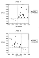
- FIG. 1 shows a plot of values of the modulus of rupture (MOR), in psi, for bars of the honeycomb article cut parallel to the channels having approximately 1290 cell/cm 2 (200 cell/inch 2 ) and approximately a 0.0508 cm (0.020 inch) thick wall, "200/20,” plotted against values of the "M T " Parameter.
- the M T " Parameter is computed from CTE, transverse I-ratio (I T ), %porosity, and d 90 pore size according to the invention as described in EQ. 2 above.
- Inventive honeycomb ceramic articles have a calculated "M T " parameter that is preferably greater than 2660 resulting in an MOR of a 200/20 cordierite honeycomb article that is greater than 58.565 bar (850 psi) (filled circles). Comparative examples have calculated "M T " parameter values that are less than 2660, and generally have MOR values of 200/20 honeycombs that are less than 58.565 bar (850 psi) (open circles).
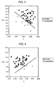
- FIG. 2 shows a plot of the values of the modulus of rupture (MOR), in psi, for bars of the honeycomb article cut parallel to the channels having approximately 1290 cell/cm 2 (200 cell/inch 2 ) and approximately a 0.0508 cm (0.020 inch) thick wall plotted against values of the "M A " Parameter.
- the "M A " Parameter is computed from CTE, axial I-ratio (I A ). %porosity, and d 90 pore size as described in EQ. 1 above.
- Inventive articles have a calculated "M A " parameter that is preferably less than 2220, resulting in an MOR of a 200/20 cordierite honeycomb article that is preferably greater than 58.565 bar (850 psi) (filled circles).
- Comparative examples have calculated "M A " parameters that are greater than 2220, and also generally have MOR values of 200/20 honeycombs that are less than 58.565 bar (850 psi) (open circles).
- FIG. 3 shows the mean CTE from 25 to 800°C in units of 10 -7 /°C along the axial direction of inventive and comparative cordierite honeycombs having d 90 less than 33 ⁇ m and porosity ⁇ 54%, plotted against the transverse I-ratio (I T ) of the same articles.
- Inventive articles filled circles
- comparative examples open circles
- FIG. 4 shows the mean CTE from 25 to 800°C in units of 10 -7 /°C along the axial direction of inventive and comparative cordierite honeycomb articles having a d 90 less than 33 microns and porosity ⁇ 54%, plotted against the axial I-ratio (I A ) of the same articles.
- Inventive bodies filled circles
- M A values less than 2220 and preferably MOR of 200/20 axial specimens greater than 58.565 bar (850 psi)
- comparative examples open circles
- M A values greater than 2220 and preferably MOR of 200/20 axial specimens less than 58.565 bar (850 psi).
- the examples of the present invention at a given CTE, have a higher degree of crystal orientation with c axes in the plane of the wall, than those of the comparative examples, resulting in a lower I A .
- higher CTE implies less microcracking.
- lower axial I-ratio implies less microcracking and, thus, higher strength.
- FIG. 5 depicts the elastic modulus, E, in psi, of bars cut parallel to the direction of the channels from 200/20 specimens, measured by a sonic resonance technique, as a function of increasing temperature (in °C) for Inventive Example 7 (solid curve) and for Comparative Example C3 (dashed curve).
- the extent to which the elastic modulus, E, increases from 25 to 1000°C is proportional to the amount of microcracking in the ceramic article.
- the smaller increase in elastic modulus, E, with temperature shows that Example 7 has a lower degree of microcracking than the comparative example. Accordingly, it has higher strength.
- FIG. 6 is a plot of the computed thermal shock parameter, TSP in °C versus the mean CTE, in 10 -7 /°C from 25-800°C, for inventive examples made with no fine kaolin (filled circles), and comparative examples made with 16% fine kaolin, (open circles).
- the thermal shock parameter (TSP) is defined in EQ. 4.
- the TSP is a measure of the article's ability to resist damage (cracking) due to temperature gradients resulting from thermal cycling. A higher TSP is beneficial. This plot demonstrates that the absence of a fine kaolin source raises the thermal shock parameter, TSP, at a given CTE.
- inventive examples having low amounts of fine kaolin will result in honeycomb articles having higher TSP for a given CTE, thereby providing better resistance to cracking when undergoing thermal cycling in use.
- Inventive examples of the present invention honeycomb article preferably exhibit TSP values ⁇ 7.3x10 3 /[CTE(25-800°C)+7.23].
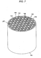
- FIG. 7 is a diagram of a honeycomb wall-flow particulate filter 100 formed of a honeycomb structure, according to the present invention.
- the honeycomb filter article 100 is composed of a body 101 having an inlet end 102, an outlet end 104, and a plurality of channels 108, 110 extending in parallel between the inlet end 102 and the outlet end 104.
- An alternating pattern of plugs 112 are arranged on inlet end 102 and outlet end 104 so that exhaust flows through the porous walls 106 of the channels 108, 110.
- the honeycomb filter article 100 may be formed of any channel density, typically 15.5 - 46.5 cells/ cm 2 (100 - 300 cells/in 2 ) and any wall thickness, typically 254 - 762 ⁇ m (0.01 to 0.03 inch), for example.
- honeycomb is intended to include materials having a generally honeycomb structure, but is not strictly limited to a hexagonal structure; for example triangular, square, rectangular, circular, combinations thereof or any other suitable channel shape may be used.
- FIG. 8 is a plot of the M T parameter versus the M A parameter for inventive examples made with not more than 8% fine kaolin or made with about 16% fine kaolin and fired at a heating rate of not more than 20°C/hr from 1200 to 1300°C, and comparative examples that either are made with at least 16% fine kaolin and fired at a heating rate of more than 20°C/hr from 1200 to 1300°C, or are made with no fine kaolin but which have an excessively coarse pore size or high porosity.
- FIG. 9 is a plot of the MOR (in psi) of the approximately 200/20 cellular specimens versus MOR (in psi) of the non-cellular rod, for inventive examples and comparative examples. As can be seen, both measures of strength are improved relative to the prior art. A higher MOR strength is beneficial because it helps with canning strength, general fatigue strength and resistance to cracking due to exposure to various vibrational environments.
- inventive porous cordierite ceramic honeycomb articles as demonstrated in FIGS. 1-6 , and 8-9 , comprise M A ⁇ 2220, according to EQ. 1, or M T > 2660, according to EQ. 2, and also exhibit a mean CTE from 25 to 800°C of not more than 9x10 -6 /°C in at least one direction.
- Such articles have improved strength while maintaining a high thermal shock resistance, and are especially advantageous for use as a honeycomb diesel particulate filter.
- the cordierite honeycomb articles preferably exhibit a % porosity of at least 40%, but less than 54%, a median pore diameter, d 50 ⁇ 10 ⁇ m; and a mean CTE (25 to 800°C) ⁇ 9 x 10 -7 /°C; and which satisfy at least one of the following two relationships: M A ⁇ 2220, according to EQ. 1, or M T > 2660, according to EQ. 2.
- the median pore diameter is at least 13 ⁇ m for low pressure drop.
- the honeycomb article exhibits both M A ⁇ 2220 and M T > 2660, and in some embodiments both M A ⁇ 2000 and M T > 2800. Certain ones of these embodiments exhibit M A ⁇ 2000 or M T > 2900. Other preferred embodiments exhibit M A ⁇ 1800 or M T > 3000.
- M A ⁇ 2220 or M T > 2660 correspond to an MOR > 850 psi for a 200/20 honeycomb article as shown in FIG. 1 and FIG. 2 . It is recognized that a body satisfying M A ⁇ 2220 or M T > 2660 will have a higher MOR for any cell geometry than an article that does not satisfy M A ⁇ 2220 or M T > 2660 for that same cell geometry. Thus, the present invention is not limited by cell geometry, and pertains to all cordierite articles satisfying M A ⁇ 2220 or M T > 2660 regardless of cell shape, cell density, or wall thickness.
- the present invention is a high-strength cordierite honeycomb article in which the mean coefficient of thermal expansion, CTE, in the axial direction from 25 to 800°C in units of 10 -7 / °C is greater than the quantity defined as [34.4 (I A ) -8.7], but CTE from 25 to 800°C is still not more than 9 x 10 -7 /°C.
- the present invention is a high-strength cordierite honeycomb article in which the mean coefficient of thermal expansion, CTE, in the axial direction from 25 to 800°C in units of 10 -7 / °C is greater than the quantity defined as [40.0 - 40.6(I T )], but is still not more than 9 x 10 -7 /°C.
- CTE mean coefficient of thermal expansion
- I A and I T the axial and transverse I-ratios
- the article has a median pore diameter, d 50 , that is preferably greater than or equal to 10 ⁇ m for low clean pressure drop and preferably less than or equal to 25 ⁇ m for high filtration efficiency, i.e., 10 ⁇ m ⁇ d 50 ⁇ 25 ⁇ m.
- the value of d 50 is more preferably 12 ⁇ m ⁇ d 50 ⁇ 22 ⁇ m; and most preferably 14 ⁇ m ⁇ d 50 ⁇ 20 ⁇ m.
- the d 90 pore diameter of the honeycomb article is preferably made low by reducing the volume fraction of large pores wherein d 90 ⁇ 40 ⁇ m for higher strength; more preferably d 90 ⁇ 33 ⁇ m, more preferably yet d 90 ⁇ 30 ⁇ m; and in some embodiments d 90 ⁇ 25 ⁇ m.
- the honeycomb exhibit a ratio, E R , of the elastic modulus, E', at 1000°C to the elastic modulus, E, at 25°C, i.e., E'(1000°C)/E(25°C), to be less than 1.20; and more preferably less than 1.10, as this also indicates a low degree of microcracking.
- the honeycomb in a 200/20 cell geometry exhibits an elastic modulus at 25 °C of less than 89.570 x 10 3 bar (1.3 x 10 6 psi), more preferably less than 82.680 x 10 3 bar (1.2 x 10 6 psi).
- the above elastic moduli (E, E') are measured by sonic resonance.
- Other preferred embodiments include cordierite honeycomb articles in which the ratio of MOR/E (strain-to-failure ratio) at about 25°C is at least 0.073%; more preferably at least 0.080%; and still more preferably at least 0.090%. This results in articles which have higher resistance to cracking while undergoing thermal cycling.
- MOR/E strain-to-failure ratio
- the article have a thermal shock parameter, TSP, defined in EQ. 4, which satisfies the relation TSP > 7.3x10 -3 /[CTE(25-800°C) + 7.23] and in which CTE(25-800°C) is in units of 10 -7 /°C.
- TSP thermal shock parameter
- the cordierite honeycomb article has an axial MOR that is greater than 58.565 bar (850 psi) when the bulk density of the body is 0.60 to 0.70 g/cm 3 .
- These bulk densities are exhibited by articles with, for example, between about 45-52% porosity, a cell density of approximately 1290 cell/cm 2 (200 cells/inch 2 ), and a wall thickness of approximately 0.0508 cm (0.020 inches).
- thermal shock resistance and strength are provided by honeycomb articles that exhibit M A ⁇ 1800 or M T > 3000, for example (See Tables 2-9).
- certain embodiments exhibit combinations of properties which exemplify articles having exceedingly good strength and thermal shock resistance.
- such embodiments of the invention See Tables 2-9) include the combination of %porosity ⁇ 52%, d 90 ⁇ 29 ⁇ m, I A ⁇ 0.33, CTE ⁇ 8 x10 -7 /°C (25-800°C) in at least one direction, and d 50 ⁇ 10 ⁇ m.
- honeycomb embodiments exhibit other combinations of properties which are desirable in particulate filters, such as %porosity of at least 44% and not more than 53%, 10 ⁇ m ⁇ d 50 ⁇ 20 ⁇ m, d 90 ⁇ 33 ⁇ m, (d 50 -d 10 )/d 50 ⁇ 0.55, and CTE ⁇ 8x10 -7 /°C (25-800°C) (or even CTE ⁇ 6x10 -7 /°C) in at least one direction.
- Such filter articles exhibit low clean and soot-loaded back pressure, as well as excellent strength and thermal shock resistance.
- porous cordierite ceramic honeycomb article of the invention include %porosity of at least 46% and not more than 53%, 12 ⁇ m ⁇ d 50 ⁇ 19 ⁇ m, d 90 ⁇ 30 ⁇ m, (d 50 -d 10 )/d 50 ⁇ 0.50, and CTE ⁇ 8x10 -7 /°C (25°C to 800°C) in at least one direction.
- Such embodiments exhibit good clean and soot loaded pressure drops, as well as good strength and thermal shock resistance.
- Certain of these embodiments exhibit very low d-factor, wherein (d 50 -d 10 )/d 50 ⁇ 0.40 (See Tables 2-9) thus providing very low clean pressure drop.
- the present invention also provides a method of manufacturing a high-strength cordierite-containing honeycomb article having a CTE of not more than 9x10 -7 /°C and having M A ⁇ 2220 or M T > 2660 (preferably M A ⁇ 2220 and M T > 2660), and a batch therefor.
- the method involves mixing inorganic raw materials with processing aids and an optional pore former to form a plasticized batch mixture, forming the plasticized batch mixture into a honeycomb structure, and then firing the honeycomb structure to form the honeycomb article according to further embodiments of the invention.
- only so much of the pore former is utilized to produce a fired honeycomb article having less than 54% porosity. Limiting porosity achieves higher strength.
- the inorganic raw materials contain a talc (preferably a platy talc), an alumina-forming source, a silica-forming source, and 0-18% kaolin or calcined kaolin.
- the inorganic raw material mixture preferably includes little or no fine kaolin source (defined herein as having a median particle diameter of less than 7 ⁇ m). If a fine kaolin source is present, it is preferably present in an amount less than 8 wt. % of the batch inorganic materials; more preferably not more than 4 wt. %; and more preferably yet not more than 2 wt. %. In some embodiments, the batch is entirely absent of fine kaolin.
- the average heating rate between 1200 and 1300°C is not more than 20°C/hr, and is preferably not more than 10°C/hr, and the weighted average median particle diameter of the alumina-forming sources is not less than 5 ⁇ m.
- the average heating rate between two temperatures is defined as the difference between the two temperatures divided by the time during which the kiln temperature is between those two temperatures.
- the batch is entirely absent of any kaolin or calcined kaolin.
- All particle diameters herein are based upon a particle volume distribution as measured by laser diffraction on a suspension of the powders in a liquid, such as in water or isopropyl alcohol or a mixture thereof, using a particle size analyzer, such as a Model FRA9200 or Model S3000 Microtrac particle analyzer (products of Microtrac Inc.).
- the median particle diameter is thus the particle diameter at which 50% of the particles are of a smaller diameter, and 50% are of a larger diameter, based upon cumulative volume.
- the alumina-forming source is preferably present in an amount of about 34 to 38 wt. %.
- the weighted average of the median particle diameters of the alumina-forming sources preferably is at least 5 ⁇ m, and in some embodiments at least 6 ⁇ m.
- W is the weight percentage of each alumina-forming source in the raw material mixture
- d 50 is the median particle diameter of each alumina-forming source
- Al-1, Al-2, ...Al-n represent each alumina-forming source used in the mixture.
- Alumina-forming sources are compounds capable of forming Al 2 O 3 upon heating, and include, for example, corundum, a transition alumina such as gamma-alumina and rho-alumina, boehmite, diaspore, and gibbsite.
- the alumina-forming source includes, in part, a highly dispersible powder, such as boehmite, having a median particle diameter of less than 1 ⁇ m, preferably less than 0.5 ⁇ m, and more preferably less than 0.2 ⁇ m, which comprises not more than 10 wt. % of the inorganic raw materials.
- the silica-forming source includes, but is not limited to, quartz, cristobalite, cryptocrystalline silica, non-crystalline silica such as fused silica, and diatomaceous silica, and combinations thereof. Quartz or cryptocrystalline silica are most preferred.
- the silica-forming source is preferably present in the amount of between 10 and 24 wt. % and preferably has a median particle diameter of at least 10 ⁇ m; and more preferably yet at least 20 microns. Most preferably the silica source has a median particle diameter of less than 35 ⁇ m.
- the preferred talc has a median particle diameter greater than about 15 ⁇ m, and preferably greater than about 20 ⁇ m, but preferably has a median particle diameter less than 35 micrometers.
- the median particle diameter of the talc source or the silica-forming source is at least 7 ⁇ m.
- the talc is preferably provided in an amount of between 38 and 42 wt. % of the total inorganic materials.
- the talc preferably has an XRD talc morphology index of between 0.6 and 1.0, for example.
- the talc morphology index is more preferably at least 0.85.
- the value of the XRD talc morphology index can range from 0.0 to 1.0 and is proportional to the aspect ratio, or platy character, of the talc particles.
- Talc having a very platy morphology will have a high morphology index.
- the talc morphology index is measured by x-ray diffractometry on a talc powder that is packed into the x-ray diffraction sample holder to maximize the orientation of the talc within the plane of the sample holder, as described in United States Patent 5,258,150 .
- the raw material mixture further contains forming aids and may optionally contain a pore forming agent.
- the forming aids include a vehicle, such as water, a binder, such as a methylcellulose material, and a lubricant, such as sodium stearate.
- the pore forming agent if provided, is only provided in an amount sufficient to ensure that the porosity of the fired honeycomb article is at least 40% and less than 54%. Pore forming agents in the amount of less than about 20% by wt. of the inorganic raw materials are required to meet this level of porosity.
- Preferred pore forming agents include graphite, potato starch, and polyethylene beads.
- the dry ingredients are then mixed with the vehicle, such as with water, and kneaded in a preferably stainless steel muller or double-arm mixer or screw-type mixer, for example, to form an extrudable plastic batch mixture.
- the plastic batch mixture is then formed, preferably by extrusion, into a green body, as described in US 5,205,991 , for example.
- the cellular honeycomb green bodies are cut to a log length.
- the honeycomb.green bodies are dried in a suitable conventional RF or microwave dryer apparatus and then cut to a suitable final part length.
- the honeycomb article is fired in a suitable furnace.
- the article is preferably fired at a top hold temperature between about 1390 to 1440 °C for 4 to 40 hours to form a body with a predominant phase of cordierite, preferably including at least 92% cordierite. More preferably, the article is formed by firing at between 1415 and 1435 °C for 12-35 hours.
- the heating rate from 1300 to 1390°C should be not less than 20°C/hr, and when the median particle diameter of the talc source is less than 10 ⁇ m, the heating rate from 1300 to 1390°C should be not less than 40°C/hr.
- the average heating rate from 1200 to 1300°C should be not more than 20°C/hr ; more preferably not more than 15°C/hr ; and most preferably not more than 10°C/hr.
- the heating rate from 1300 to 1390°C should be not less than 20°C/hr, and when the median particle diameter of the talc source is less than 10 ⁇ m, the heating rate from 1300 to 1390°C should be not less than 40°C/hr.
- Table 1 provides the median particle diameter of the raw material powders as measured by laser diffraction using a Microtrac particle analyzer as described above.
- Tables 2 to 18 Inventive and comparative examples of 2-inch and 5.66-inch diameter extrusions having approximately 200 cells/inch 2 and approximately 0.020-inch walls are presented in Tables 2 to 18. All example batches were made with 4% to 6% methylcellulose binder, and 0.5 to1% of a sodium stearate lubricant. In each of the Tables the batch materials are described in percent by weight solids without regard to liquid processing aids such as water and binder materials.
- Some of the fired honeycomb bodies were plugged at the ends of alternate channels in a checkerboard pattern such that a channel that was plugged at one end was open at the other end, thereby forming a wall-flow filter.
- the pressure drop across the filter bodies was measured as follows. Each filter was wrapped in a ceramic fibrous mat and securely encased in a cylindrical metal holder. The holder and filter were attached at each end to metal pipes through which a stream of air was passed. The pressure drop across the filter, that is, the pressure difference between the inlet and outlet faces, was measured as a function of gas flow rate.
- Flow rates of 53.8 to 743.32 standard cubic liters per minute (slm) (1.9 to 26.25 standard cubic feet per minute (scfm)) were utilized for all 5.08 cm (2-inch) diameter samples, and flow rates of 424.75 to 5946.57 slm (15 to 210 scfm) were used for the 14,37 (5.66") diameter filters.
- a flow rate of 26.25 scfm through a 2-inch diameter filter is of approximately the same gas space velocity as a flow rate of 210 scfm through a 14,37 cm (5.66-inch) diameter filter of the same length, equal to 144,000 hr -1 for a 15,24 cm (6-inch) long filter.
- a clean pressure drop measured at 5946.57 slm (210 scfm) through a 14.37 x 15.24 cm (5.66 x 6 inch) filter can be directly compared to the clean pressure drop measured at 743.32 slm (26.25 scfm) through a 5.08 x 15.24 cm (2 x 6 inch) filter because the gas space velocities are approximately equivalent.
- the conditions of the test method described above are meant to provide a relative comparison of the behaviors of the filters in environments of flowing gas and carbon soot build-up on the walls of the filter, analogous to the environment that a filter would experience if placed in the exhaust path of a diesel engine.
- the pressure drop of a filter that is loaded with a given mass per volume of carbon soot be as low as possible.
- Tables 2 and 3 provide numerous examples of compositions used in the present invention article. All modulus of rupture (MOR) values of inventive examples are greater than 58.565 cm (850 psi) as measured on a cellular bar (2.54 cm x 1.27 cm x 12.7 cm 10mg; 1290 cell/cm 2 , 0.0508 cm wall thickness) ((1 inch x 1 ⁇ 2 inch x 5 inch long; 200 cells/in 2 , 0.020 inch wall thickness)). Examples 1-12 are substantially absent (free) of kaolin.
- MOR modulus of rupture
- Examples 5 and 7-9 show a high strain-to-failure as exemplified by a high (MOR/E) of greater than 0.073 %; more preferably between 0.077 % to 0.111 %.
- these strains-to-failure yield calculated thermal shock parameters, TSP, of greater than or equal to 550 °C; more preferably of between 563°C and 808°C.
- TSP thermal shock parameters
- Tables 4, 8, and 9 provide examples of the present invention honeycomb article that contain kaolin (specifically Kaolin A and B).
- Examples 13-17 in Table 4 demonstrate that inventive properties can be obtained with as much as 16% of a coarse kaolin (Kaolin A).
- Examples 18 in Table 4 and Examples 39 to 42 in Table 8 show that the inventive articles are achieved with 6% or 8% of a fine kaolin source.
- Examples 43 to 48 in Table 9 demonstrate that inventive properties may be obtained with up to 16% of a fine kaolin source (Kaolin B), but only when the average heating rate from 1200 to 1300°C is not more than 20°C/hr.
- Tables 10 to 15 provide additional details of the pore size distributions. for inventive examples from the Tables. These values are derived from the mercury porosimetry measurements obtained for each example. Included are the total pore volume, TPV, equivalent to the total mercury intrusion volume, in units of cm 3 /g, and the percentages of the total pore volume comprised of pores with diameters finer than 1, 2, 3, 4, 5, 6, 10, 15, 20, 25, 30, 40, 50, 60, 70, 80, 90, and 100 ⁇ m. The percentage of the TPV greater than a given pore diameter may be computed by subtracting the value in the Table from 100. The percentage of the TPV lying between any two limiting pore diameters may be computed by taking the difference between the percent values for those two pore diameters in the Table.
- Tables 16 and 17 demonstrate that when about 16% fine kaolin, having a median particle diameter less than 7 ⁇ m, is present in the raw material mixture and the heating rate from 1200 to 1300°C is greater than 20°C/hr, the MOR of a 200/20 cellular specimen is less than 850 psi and the M A and M T values lie outside the range of the invention. This demonstrates the importance of minimizing the use of fine kaolin in the batch or maintaining a slow average heating rate (less than 20°C/hr) between 1200 and 1300°C.
- the steep increase in elastic modulus with temperature is due to the higher degree of microcracking in the comparative bodies made with 16% of a kaolin having a median particle diameter less than 7 ⁇ m and a 1200-1300°C heating rate of more than 20°C/hr.
- the comparative samples made with 16% fine kaolin also possess lower strains-to-failure, MOR/E, i.e., less than 0.073%, than those made without kaolin. This results in lower values for the thermal shock parameter, as shown in FIG. 6 .
- Table 18 provides comparative examples made without fine kaolin in the raw material mixture, but for which the values of M A and M T lie outside the range of the present invention due to an excessively large value of d 90 > 40 ⁇ m (Examples C14 to C16) or due to a high porosity >54% (Examples C16 to C19).
- Table 1 Raw Materials Raw Material Median Particle Diameter by Laser Diffraction ( ⁇ m) XRD Talc Morphology Index Talc A 28 0.94 Talc B 24 0.94 Talc C 15 0.65 Talc D Approx. 40 0.95 Talc E Approx. 30 0.95 Talc F Approx.
Landscapes
- Chemical & Material Sciences (AREA)
- Chemical Kinetics & Catalysis (AREA)
- Physics & Mathematics (AREA)
- Geometry (AREA)
- Engineering & Computer Science (AREA)
- Ceramic Engineering (AREA)
- Structural Engineering (AREA)
- Materials Engineering (AREA)
- Organic Chemistry (AREA)
- Thermal Sciences (AREA)
- Manufacturing & Machinery (AREA)
- Inorganic Chemistry (AREA)
- Life Sciences & Earth Sciences (AREA)
- Geology (AREA)
- Filtering Materials (AREA)
- Compositions Of Oxide Ceramics (AREA)
- Porous Artificial Stone Or Porous Ceramic Products (AREA)
- Catalysts (AREA)
Description
- The present invention relates to a porous cordierite ceramic honeycomb article. More particularly, the invention is directed to a cordierite honeycomb article having improved strength and thermal shock resistance.
- Diesel engines provide lower emissions and increased fuel economy compared to gasoline engines; however, environmental hazards may be posed by diesel exhaust emissions. Diesel particulate filters are now being deployed to control particulate emissions from diesel-powered equipment such as trucks, buses, diesel electric locomotives and generators. In particular, diesel particulate filters control particulate emissions by physically trapping soot particles in their structure. Diesel particulate filters are preferably constructed as wall-flow monoliths, which allow exhaust gases to flow through their porous ceramic walls, while any particulate present in the exhaust gas is collected on the upstream side of the wall. Once a predetermined condition is met, the filter may be cleaned by a regeneration cycle, during which the temperature of the exhaust gas is high enough to ignite and bum out any particulate soot. This regeneration cycle reduces the backpressure of the diesel particulate filter near to that of a new filter. The surface of the walls or the porous interior of the walls may include a catalyst wash coat containing platinum (Pt), palladium (Pd), iron (Fe), strontium (Sr) or rare earth elements such as cerium (Ce) to lower the temperature required for regeneration of the filter and to convert hydrocarbons and carbon monoxide in the exhaust gases into non-hazardous water vapor and carbon dioxide.
- One preferred material for the manufacture of high temperature components is cordierite (Mg2Al4Si5O18), a magnesium aluminum silicate, that often includes low levels of iron or other impurities. Cordierite is a desired material for the manufacture of diesel particulate filters and other high temperature articles, such as catalytic converters, NOx adsorber substrates, catalyst substrates, and honeycomb articles because of its relatively low cost. Cordlerite materials are typically manufactured by mixing a raw batch that includes talc, alumina, aluminum hydroxide, kaolin and silica. The batch is then blended with a binder (such as methylcellulose) and a lubricant (such as sodium stearate) to form a plastic mixture. This plastic mixture is then formed into a green body and sintered.
U.S. Patent No. 6,864,198 assigned to Coming Incorporated discloses one method of forming a cordierite honeycomb structure. - During the regeneration of a cordierite DPF, heating of the core region creates a large thermal gradient across the radius of the filter, such that, for example, the core may be at 800°C to 1000°C while the periphery near the skin is at 400°C to 500°C. Due to the positive coefficient of thermal expansion, CTE, of cordierite from 400 to 1000°C, the filter's core expands in the axial direction more than does the filter's outer shell. Consequently, strain is created between the skin and the core such that the core is in compression and the skin is in tension. If the stresses are sufficiently large, the skin may fracture, creating one or more cracks than encircle part or all the filter's circumference, orthogonal to the axial direction. Likewise, axial thermal gradients along the length of the filter may result in the face of the filter (inlet or outlet end) having a lower temperature than the interior of the filter. In such cases the face will be in tension, and face-cracking may occur. Such fractures of either type may compromise the filter's mechanical integrity, or filtration efficiency. Accordingly, cordierite filter articles which have better resistance to the formation of such cracks are highly desired.
- Thermal stresses can be reduced by regenerating the filter more frequently before large amounts of soot can accumulate, thereby reducing both the maximum internal temperature and thermal gradient. However, increasing the frequency with which energy is supplied to raise the temperature of the exhaust gas entering the filter and, thus, initiate regeneration, results in lower fuel economy.
- Document
WO 99/43629 A1 - Thus, it would be highly desirable to increase the filter's intrinsic thermal stress resistance, so that regeneration cycles may occur less frequently.
- Thus, cordierite honeycomb articles having increased strength for greater mechanical durability, in combination with higher thermal shock resistance are much sought after. Such increases in strength and thermal shock resistance cannot, however, come at the expense of other important properties, such as clean pressure drop, and filtration efficiency, for example. Accordingly, there is a need for cordierite articles which exhibit improved strength and durability in regards to exposure to thermal cycles.
- The present invention provides an improved porous ceramic cordierite honeycomb article with increased mechanical strength and thermal shock resistance for a given percent porosity, pore size distribution, and coefficient of thermal expansion. Embodiments of the porous ceramic cordierite honeycomb article of the present invention and a method for its manufacture are disclosed herein.
- Advantageously, the present invention includes a reduced amount of microcracking while increasing the volume fraction of cordierite crystals having their negative-CTE crystallographic "c-axes" aligned within the plane of the honeycomb wall, while reducing the volume fraction of cordierite crystals having their positive-CTE crystallographic "a- and b-axes" aligned within the plane of the honeycomb wall. Thus, desirably, the strength of the honeycomb article is increased due to less microcracking, while low CTE is maintained due to increased cordierite crystal orientation with their "c-axes" parallel to the plane of the wall.
- As such, the present invention provides a unique combination of porosity, pore size distribution, coefficient of thermal expansion, and crystallite orientation within the walls of the article to provide increased strength while maintaining a high thermal shock parameter, TSP. Specifically, the inventors herein have discovered that porous cordierite ceramic honeycomb articles have improved strength and a high thermal shock parameter, TSP, when their porosity, pore size distribution, CTE, and crystal orientation within the walls satisfy the following relationships:

or
where
and
and wherein the mean CTE from 25 to 800°C is not more than 9x10⁻⁷/°C in at least one direction, and a median pore diameter, d50, wherein 10 µm ≤ d50 ≤ 25 µm. - In EQ. 1 and 2 above, CTE is the mean coefficient of thermal expansion from 25 to 800°C in units of 10-7/°C as measured by dilatometry on a specimen parallel to the lengths of the channels of the honeycomb article. Thus, a CTE of 8.0 x 10⁻⁷ °C-1 would be entered as "8.0" in both EQ. 1 and EQ. 2. The %porosity is the volume percentage of porosity in the walls of the article as measured by mercury porosimetry, and can, in principle, range from 0 to nearly 100 (though typically only up to about 80%), and is dimensionless. Thus, a %porosity of 45% would be entered as "45" in both EQ. 1 and EQ. 2. The term d90 is measured by mercury porosimetry and is the pore diameter, in µm, at which 90% (by volume) of the pores have a smaller diameter (equal to the pore diameter at which the cumulative mercury intrusion volume equals 10% of the total mercury intrusion volume). A value of d90 equal to 30 µm would be entered as "30" in both EQ. 1 and EQ. 2, for example. IA is the axial XRD I-ratio (I-ratio measured on the axial cross section of the honeycomb) and IT is the transverse XRD I-ratio (I-ratio measured on the transverse, as-fired wall surface). The I-ratio is defined by the relationship:

where I(110) and I(002) are the peak heights of the XRD reflections from the (110) and (002)iplanes in the cordierite crystal lattice, based upon hexagonal indexing of the XRD peaks. The I-ratio is measured by x-ray diffractometry using copper Kα radiation on either the axial cross section (orthogonal to the length of the channels) or the transverse surface (as-fired surface of the honeycomb walls). The values of IA and IT can range from 0.0 to 1.0, and are dimensionless. - According to preferred embodiments of the invention, the porous honeycomb article has a porosity of at least 40%, but less than 54%, and a median pore diameter, d50 ≥ 13 µm. The median pore diameter, d50, is the pore diameter at which the cumulative mercury intrusion volume equals 50% of the total mercury intrusion volume. According to additional embodiments of the invention, MA < 2000 or MT > 2900; or even MA < 1800 or MT > 3000.
- Additionally, the honeycomb article of the present invention may also exhibit a thermal shock parameter, TSP, that is at least 550°C, where the TSP is defined by the following relationship:

where MOR is the modulus of rupture, measured at room temperature (25°C) by the four-point loading method on a 1 inch x 0.5 inch x 5 inch bar cut parallel to the length of the channels (hereafter referred to as the "axial direction"), E is the elastic modulus, also known as Young's modulus, measured in the axial direction at room temperature (25°C) by a sonic resonance technique on a 2.54 cm x 1.27 cm x 1.27 cm (1 inch x 0.5 inch x 5 inch) bar, and CTE' is the mean coefficient of thermal expansion measured in the axial direction during heating from 500 to 900° C by dilatometry on a 0.635 cm x 0.635 cm x 5.08 cm (0.25 inch x 0.25 inch x 2 inch) bar. A CTE' of 8x10⁻⁷/°C would be entered as "8x10⁻⁷/°C" in EQ. 4, an elastic modulus of 82.68 x 10³ bar (1.2x10⁶ psi) would be entered as "82.69x103" in EQ. 4, and an MOR of 68.9 bar (1000 psi) would be entered as "68.9" in EQ. 4. - The method for manufacturing a cordierite honeycomb article is described below: The method preferably includes the steps of: mixing inorganic raw materials containing talc, an alumina-forming source, a silica-forming source, and 0 - 18 wt. % of a kaolin or calcined kaolin containing not more than 8 wt. % of a fine kaolin source having a median particle diameter of less than 7 µm, or if greater than 8 wt. % of the fine kaolin source then using a slow ramp rate during firing, with processing aids and optionally a pore forming agent to form a plasticized mixture; forming the plasticized mixture into a honeycomb structure; and firing the honeycomb structure to form the porous ceramic cordierite honeycomb article having a porosity < 54% wherein if greater than 8 wt. % fine kaolin source is used, then the slow ramp rate includes a heating rate from 1200 to 1300°C of not more than 20°C/hr; and wherein the porous ceramic cordierite honeycomb article comprises: MA < 2220, or MT > 2660, wherein MA = 3645 (IA) - 106 (CTE) + 19 (d90) + 17 (%porosity), MT = 4711 (IT) + 116 (CTE) - 26 (d90) - 28 (%porosity), and CTE from 25 to 800°C of not more than 9x10⁻⁷/°C and a median pore diameter, d50, wherein 10 µm ≤ d50 ≤ 25 µm. In other words, a higher weight % of fine kaolin may be tolerated and still achieve desirable end properties, as long as the heating rate within the temperature range of 1200-1300°C is low enough. The inorganic raw material batch mixture may be formed into or otherwise used on a honeycomb article by any known techniques including: doctor-blading, spraying, tape-casting, calendaring, painting or extrusion. The raw material mixture may also be used for a coating, plug or skin on honeycomb ceramic article, and may be extruded to form the honeycomb article. A finished honeycomb article is preferably prepared by firing at a temperature and time sufficient to form a ceramic having a high percentage of cordierite.
- The honeycomb article of the present invention is useful, and best embodied, as a high temperature honeycomb article, such as diesel particulate filters, a catalytic converter, a NOx adsorber, a catalyst substrate, or a flow filter body for high temperature fluids or in other high temperature applications.
-
-
FIG. 1 shows a plot of MOR values (psi) versus the "MT" Parameter computed using EQ. 2 according to the invention. -
FIG. 2 shows a plot of MOR values versus the "MA" Parameter computed using EQ. 1 according to the invention. -
FIG. 3 shows CTE (10-7/°C) versus the transverse I-ratio, IT according to the invention. -
FIG. 4 shows CTE (10-7/°C) versus the axial I-ratio, IA according to the invention. -
FIG. 5 depicts the elastic moduli (E) in psi as a function of increasing temperature for Inventive Example 7 and for Comparative Example C3. -
FIG. 6 is a plot of the computed thermal shock parameter, TSP (°C) versus CTE (10-7/°C) for examples made with no fine kaolin according to embodiments of the invention and comparative examples made with 16% fine kaolin. -
FIG. 7 is an isometric view of a honeycomb wall-flow particulate filter article according to an exemplary embodiment of the present invention. -
FIG. 8 is a plot of "MT" Parameter versus "MA" Parameter according to embodiments of the present invention. -
FIG. 9 is a plot of MOR of Cellular versus MOR of Non-cellular Rod according to embodiments of the present invention. - The present invention is an improved porous ceramic cordierite article having improved material strength and low CTE. As used herein, CTE shall refer to the mean coefficient of thermal expansion (from 25 to 800°C) as measured by dilatometry parallel to the length of the channels (axial direction), unless otherwise specified. As was discovered by the inventors herein, a reduction in microcracking in the article is primarily responsible for the increase in strength, while alignment of the cordierite crystals is primarily responsible for achieving low CTE. Both have been achieved simultaneously.
- In particular, the cordierite honeycomb article of the present invention advantageously exhibits increased alignment of the c-axes of the cordierite crystals with the plane of the walls of the honeycomb article. The c-axis of cordierite crystals has a negative CTE and by aligning the c-axes, the present invention provides a low CTE in any direction that is parallel to the plane of the wall in the cordierite article. It has been discovered that reducing or eliminating the kaolin, especially any fine kaolin, from the raw material mixture increases the degree of alignment of the c-axes of the cordierite crystals with the plane of the honeycomb wall and improves (reduces) the axial CTE (that is, CTE in the axial direction of the honeycomb) of the finished (fired) article. It has also been discovered that reducing or eliminating fine kaolin from the raw material mixture reduces the amount of microcracking in the fired article. A reduction in microcracking tends to increase the CTE of the fired article, but also increases the modulus of rupture and the elastic modulus.
- The strength of a cordierite honeycomb article is important for thermal shock resistance as well as long-term mechanical durability (resistance to mechanical failure) when used in an application in which there is considerable vibration, such as a flow-through catalytic converter or wall-flow diesel particulate filter. The intrinsic strength of the wall of the honeycomb article is also limited by the amount of porosity in the body and by the size and volume percentage of the largest pores, as well as by the degree of microcracking.
- It has been discovered that, when the values of certain measurable microstructural properties lie within a specific range, the strength of the honeycomb body is enhanced without sacrificing the coefficient of thermal expansion, and the thermal shock resistance is preserved or even increased. This is especially important when the honeycomb article is used as a particulate filter, because porosities greater than 40% are desirable to achieve low pressure drop across the filter, and high porosity tends to reduce the strength of the body. Thus, porosity should preferably be less than 54%. While a variety of median pore diameters are useful, the optimum median pore diameter, d50, is 10 µm ≤ d50 ≤ 25 µm, which provides a balance between pressure drop and particulate filtration. At median pore diameters below about 10 µm, pressure required to force particulate laden gases through the wall increases and may interfere with the operation of an internal combustion engine. At median pore diameters above about 25 µm, particulates may pass through the filter, decreasing filtration efficiency.
-
FIG. 1 shows a plot of values of the modulus of rupture (MOR), in psi, for bars of the honeycomb article cut parallel to the channels having approximately 1290 cell/cm2 (200 cell/inch2) and approximately a 0.0508 cm (0.020 inch) thick wall, "200/20," plotted against values of the "MT" Parameter. The MT" Parameter is computed from CTE, transverse I-ratio (IT), %porosity, and d90 pore size according to the invention as described in EQ. 2 above. Inventive honeycomb ceramic articles have a calculated "MT" parameter that is preferably greater than 2660 resulting in an MOR of a 200/20 cordierite honeycomb article that is greater than 58.565 bar (850 psi) (filled circles). Comparative examples have calculated "MT" parameter values that are less than 2660, and generally have MOR values of 200/20 honeycombs that are less than 58.565 bar (850 psi) (open circles). -
FIG. 2 shows a plot of the values of the modulus of rupture (MOR), in psi, for bars of the honeycomb article cut parallel to the channels having approximately 1290 cell/cm2 (200 cell/inch2) and approximately a 0.0508 cm (0.020 inch) thick wall plotted against values of the "MA" Parameter. The "MA" Parameter is computed from CTE, axial I-ratio (IA). %porosity, and d90 pore size as described in EQ. 1 above. Inventive articles have a calculated "MA" parameter that is preferably less than 2220, resulting in an MOR of a 200/20 cordierite honeycomb article that is preferably greater than 58.565 bar (850 psi) (filled circles). Comparative examples have calculated "MA" parameters that are greater than 2220, and also generally have MOR values of 200/20 honeycombs that are less than 58.565 bar (850 psi) (open circles). -
FIG. 3 shows the mean CTE from 25 to 800°C in units of 10-7/°C along the axial direction of inventive and comparative cordierite honeycombs having d90 less than 33 µm and porosity < 54%, plotted against the transverse I-ratio (IT) of the same articles. Inventive articles (filled circles) exhibit "MT values greater than 2660 and preferably MOR of 200/20 axial specimens greater than 58.565 bar (850 psi) whereas comparative examples (open circles) have "MT" values less than 2660 and generally have MOR of 200/20 axial specimens that are less than 58.565 bar (850 psi). The diagonal line separating the two groups is given by the equation CTE = 40.0 - 40.6(IT). It should be recognized that for a given CTE, the examples of the present invention have a higher degree of crystal orientation with c axes in the plane of the wall (higher IT). A higher degree of orientation (higher IT) alone would have the effect of lowering CTE. Because CTE is affected by both crystal orientation and microcracking, if an inventive article has the same CTE but a higher degree of orientation than a comparative article, then the inventive article has a lower amount of microcracking to offset the reduction in CTE that would otherwise occur due to better orientation. Thus, for a given transverse I-ratio (IT), higher CTE implies less microcracking. Likewise, for a given CTE, higher transverse I-ratio (IT) implies less microcracking. Less microcracking is desirable in that it produces an article having greater strength. -
FIG. 4 shows the mean CTE from 25 to 800°C in units of 10-7/°C along the axial direction of inventive and comparative cordierite honeycomb articles having a d90 less than 33 microns and porosity < 54%, plotted against the axial I-ratio (IA) of the same articles. Inventive bodies (filled circles) have "MA" values less than 2220 and preferably MOR of 200/20 axial specimens greater than 58.565 bar (850 psi), whereas comparative examples (open circles) have "MA" values greater than 2220 and preferably MOR of 200/20 axial specimens less than 58.565 bar (850 psi). The diagonal line separating the two groups is given by the equation CTE = 34.4 (IA) - 8.7. The examples of the present invention, at a given CTE, have a higher degree of crystal orientation with c axes in the plane of the wall, than those of the comparative examples, resulting in a lower IA. For a given axial I-ratio, higher CTE implies less microcracking. For a given CTE, lower axial I-ratio implies less microcracking and, thus, higher strength. -
FIG. 5 depicts the elastic modulus, E, in psi, of bars cut parallel to the direction of the channels from 200/20 specimens, measured by a sonic resonance technique, as a function of increasing temperature (in °C) for Inventive Example 7 (solid curve) and for Comparative Example C3 (dashed curve). The extent to which the elastic modulus, E, increases from 25 to 1000°C is proportional to the amount of microcracking in the ceramic article. The smaller increase in elastic modulus, E, with temperature shows that Example 7 has a lower degree of microcracking than the comparative example. Accordingly, it has higher strength. -
FIG. 6 is a plot of the computed thermal shock parameter, TSP in °C versus the mean CTE, in 10-7/°C from 25-800°C, for inventive examples made with no fine kaolin (filled circles), and comparative examples made with 16% fine kaolin, (open circles). The thermal shock parameter (TSP) is defined in EQ. 4.
The TSP is a measure of the article's ability to resist damage (cracking) due to temperature gradients resulting from thermal cycling. A higher TSP is beneficial. This plot demonstrates that the absence of a fine kaolin source raises the thermal shock parameter, TSP, at a given CTE. Thus, such inventive examples having low amounts of fine kaolin will result in honeycomb articles having higher TSP for a given CTE, thereby providing better resistance to cracking when undergoing thermal cycling in use. The curve shown inFIG. 6 corresponds to the equation TSP = 7.3x10³ / [CTE(25-800°C)+7.23], where CTE(25-800°C) is in units of 10-7/°C. Inventive examples of the present invention honeycomb article preferably exhibit TSP values ≥ 7.3x10³/[CTE(25-800°C)+7.23]. -
FIG. 7 is a diagram of a honeycomb wall-flow particulate filter 100 formed of a honeycomb structure, according to the present invention. Thehoneycomb filter article 100 is composed of abody 101 having aninlet end 102, anoutlet end 104, and a plurality ofchannels inlet end 102 and theoutlet end 104. An alternating pattern ofplugs 112 are arranged oninlet end 102 and outlet end 104 so that exhaust flows through theporous walls 106 of thechannels honeycomb filter article 100 may be formed of any channel density, typically 15.5 - 46.5 cells/ cm2 (100 - 300 cells/in2) and any wall thickness, typically 254 - 762 µm (0.01 to 0.03 inch), for example. For the purpose of this application the term honeycomb is intended to include materials having a generally honeycomb structure, but is not strictly limited to a hexagonal structure; for example triangular, square, rectangular, circular, combinations thereof or any other suitable channel shape may be used. -
FIG. 8 is a plot of the MT parameter versus the MA parameter for inventive examples made with not more than 8% fine kaolin or made with about 16% fine kaolin and fired at a heating rate of not more than 20°C/hr from 1200 to 1300°C, and comparative examples that either are made with at least 16% fine kaolin and fired at a heating rate of more than 20°C/hr from 1200 to 1300°C, or are made with no fine kaolin but which have an excessively coarse pore size or high porosity. -
FIG. 9 is a plot of the MOR (in psi) of the approximately 200/20 cellular specimens versus MOR (in psi) of the non-cellular rod, for inventive examples and comparative examples. As can be seen, both measures of strength are improved relative to the prior art. A higher MOR strength is beneficial because it helps with canning strength, general fatigue strength and resistance to cracking due to exposure to various vibrational environments. - The inventive porous cordierite ceramic honeycomb articles, as demonstrated in
FIGS. 1-6 , and8-9 , comprise MA < 2220, according to EQ. 1, or MT > 2660, according to EQ. 2, and also exhibit a mean CTE from 25 to 800°C of not more than 9x10⁻⁶/°C in at least one direction. Such articles have improved strength while maintaining a high thermal shock resistance, and are especially advantageous for use as a honeycomb diesel particulate filter. According to certain embodiments of the invention, the cordierite honeycomb articles preferably exhibit a % porosity of at least 40%, but less than 54%, a median pore diameter, d50 ≥ 10 µm; and a mean CTE (25 to 800°C) ≤ 9 x 10⁻⁷/°C; and which satisfy at least one of the following two relationships: MA < 2220, according to EQ. 1, or MT > 2660, according to EQ. 2. According to other embodiments of the invention, the median pore diameter is at least 13 µm for low pressure drop. Preferably the honeycomb article exhibits both MA < 2220 and MT > 2660, and in some embodiments both MA < 2000 and MT > 2800. Certain ones of these embodiments exhibit MA < 2000 or MT > 2900. Other preferred embodiments exhibit MA < 1800 or MT > 3000. - Values of MA < 2220 or MT > 2660 correspond to an MOR > 850 psi for a 200/20 honeycomb article as shown in
FIG. 1 and FIG. 2 . It is recognized that a body satisfying MA < 2220 or MT > 2660 will have a higher MOR for any cell geometry than an article that does not satisfy MA < 2220 or MT > 2660 for that same cell geometry. Thus, the present invention is not limited by cell geometry, and pertains to all cordierite articles satisfying MA < 2220 or MT > 2660 regardless of cell shape, cell density, or wall thickness. - In a preferred embodiment, the present invention is a high-strength cordierite honeycomb article in which the mean coefficient of thermal expansion, CTE, in the axial direction from 25 to 800°C in units of 10-7/ °C is greater than the quantity defined as [34.4 (IA) -8.7], but CTE from 25 to 800°C is still not more than 9 x 10⁻⁷/°C.
- Furthermore, in a preferred embodiment, the present invention is a high-strength cordierite honeycomb article in which the mean coefficient of thermal expansion, CTE, in the axial direction from 25 to 800°C in units of 10-7/ °C is greater than the quantity defined as [40.0 - 40.6(IT)], but is still not more than 9 x 10⁻⁷/°C. This restriction on CTE relative to the axial and transverse I-ratios (IA and IT) ensures a relatively lower degree of microcracking, and improved MOR while maintaining a high thermal shock parameter, TSP. According to other embodiments of the invention, the CTE ≤ 8 x 10⁻⁷/°C, and more preferably CTE ≤ 5 x 10⁻⁷/°C. it is also preferred that IA is less than 0.40; more preferably not more than 0.35, or that the IT is greater than 0.86; more preferably at least 0.90.
- The article has a median pore diameter, d50, that is preferably greater than or equal to 10 µm for low clean pressure drop and preferably less than or equal to 25 µm for high filtration efficiency, i.e., 10 µm ≤ d50 ≤ 25 µm. The value of d50 is more preferably 12 µm ≤ d50 ≤ 22 µm; and most preferably 14 µm ≤ d50 ≤ 20 µm. The d90 pore diameter of the honeycomb article is preferably made low by reducing the volume fraction of large pores wherein d90 ≤ 40 µm for higher strength; more preferably d90 ≤ 33 µm, more preferably yet d90 ≤ 30 µm; and in some embodiments d90 ≤ 25 µm. The pore distribution is also preferably narrow, as exhibited by a value of so-called "d-factor," df = (d50-d10)/d50 which is preferably df ≤ 0.60 for low soot-loaded pressure drop; and is more preferably df ≤ 0.50; and still more preferably df ≤ 0.40; and even more preferably df ≤ 0.36. This provides low overall soot-loaded pressure drop. It is especially preferred that df ≤ 0.40 and that the %porosity is greater than or equal to 48% and less than 54%.
- Furthermore, it is preferred that the honeycomb exhibit a ratio, ER, of the elastic modulus, E', at 1000°C to the elastic modulus, E, at 25°C, i.e., E'(1000°C)/E(25°C), to be less than 1.20; and more preferably less than 1.10, as this also indicates a low degree of microcracking. Preferably, the honeycomb in a 200/20 cell geometry exhibits an elastic modulus at 25 °C of less than 89.570 x 10³ bar (1.3 x 10⁶ psi), more preferably less than 82.680 x 10³ bar (1.2 x 10⁶ psi). The above elastic moduli (E, E') are measured by sonic resonance.
- Other preferred embodiments include cordierite honeycomb articles in which the ratio of MOR/E (strain-to-failure ratio) at about 25°C is at least 0.073%; more preferably at least 0.080%; and still more preferably at least 0.090%. This results in articles which have higher resistance to cracking while undergoing thermal cycling.
- It is also preferred that the article have a thermal shock parameter, TSP, defined in EQ. 4, which satisfies the relation TSP > 7.3x10⁻³/[CTE(25-800°C) + 7.23] and in which CTE(25-800°C) is in units of 10-7/°C. Preferably, TSP ≥ 550°C; more preferably TSP > 700°C; and in some embodiments TSP > 800°C.
- In one specific embodiment of the invention, the cordierite honeycomb article has an axial MOR that is greater than 58.565 bar (850 psi) when the bulk density of the body is 0.60 to 0.70 g/cm3. These bulk densities are exhibited by articles with, for example, between about 45-52% porosity, a cell density of approximately 1290 cell/cm2 (200 cells/inch2), and a wall thickness of approximately 0.0508 cm (0.020 inches).
- According to other preferred embodiments of the invention, excellent thermal shock resistance and strength are provided by honeycomb articles that exhibit MA < 1800 or MT > 3000, for example (See Tables 2-9). Furthermore, certain embodiments exhibit combinations of properties which exemplify articles having exceedingly good strength and thermal shock resistance. For example, such embodiments of the invention (See Tables 2-9) include the combination of %porosity ≤ 52%, d90 ≤ 29 µm, IA ≤ 0.33, CTE ≤ 8 x10⁻⁷/°C (25-800°C) in at least one direction, and d50 ≥ 10 µm.
- Furthermore, certain honeycomb embodiments (See Tables 2-9) exhibit other combinations of properties which are desirable in particulate filters, such as %porosity of at least 44% and not more than 53%, 10 µm ≤ d50 ≤ 20 µm, d90 ≤ 33 µm, (d50-d10)/d50 ≤ 0.55, and CTE ≤ 8x10⁻⁷/°C (25-800°C) (or even CTE ≤ 6x10⁻⁷/°C) in at least one direction. Such filter articles exhibit low clean and soot-loaded back pressure, as well as excellent strength and thermal shock resistance.
- Other embodiments (See Tables 2-9) of the porous cordierite ceramic honeycomb article of the invention include %porosity of at least 46% and not more than 53%, 12 µm ≤ d50 ≤ 19 µm, d90 ≤ 30 µm, (d50-d10)/d50 ≤ 0.50, and CTE ≤ 8x10⁻⁷/°C (25°C to 800°C) in at least one direction. Such embodiments exhibit good clean and soot loaded pressure drops, as well as good strength and thermal shock resistance. Certain of these embodiments exhibit very low d-factor, wherein (d50-d10)/d50 ≤ 0.40 (See Tables 2-9) thus providing very low clean pressure drop.
- The present invention also provides a method of manufacturing a high-strength cordierite-containing honeycomb article having a CTE of not more than 9x10⁻⁷/°C and having MA < 2220 or MT > 2660 (preferably MA < 2220 and MT > 2660), and a batch therefor. The method involves mixing inorganic raw materials with processing aids and an optional pore former to form a plasticized batch mixture, forming the plasticized batch mixture into a honeycomb structure, and then firing the honeycomb structure to form the honeycomb article according to further embodiments of the invention. According to embodiments of the invention, only so much of the pore former is utilized to produce a fired honeycomb article having less than 54% porosity. Limiting porosity achieves higher strength.
- The inorganic raw materials contain a talc (preferably a platy talc), an alumina-forming source, a silica-forming source, and 0-18% kaolin or calcined kaolin. Most importantly, the inorganic raw material mixture preferably includes little or no fine kaolin source (defined herein as having a median particle diameter of less than 7 µm). If a fine kaolin source is present, it is preferably present in an amount less than 8 wt. % of the batch inorganic materials; more preferably not more than 4 wt. %; and more preferably yet not more than 2 wt. %. In some embodiments, the batch is entirely absent of fine kaolin. In cases where the batch contains greater than 8% of a fine kaolin source, the average heating rate between 1200 and 1300°C is not more than 20°C/hr, and is preferably not more than 10°C/hr, and the weighted average median particle diameter of the alumina-forming sources is not less than 5 µm. The average heating rate between two temperatures is defined as the difference between the two temperatures divided by the time during which the kiln temperature is between those two temperatures. In some embodiments, the batch is entirely absent of any kaolin or calcined kaolin. All particle diameters herein are based upon a particle volume distribution as measured by laser diffraction on a suspension of the powders in a liquid, such as in water or isopropyl alcohol or a mixture thereof, using a particle size analyzer, such as a Model FRA9200 or Model S3000 Microtrac particle analyzer (products of Microtrac Inc.). The median particle diameter is thus the particle diameter at which 50% of the particles are of a smaller diameter, and 50% are of a larger diameter, based upon cumulative volume.
- The alumina-forming source is preferably present in an amount of about 34 to 38 wt. %. The weighted average of the median particle diameters of the alumina-forming sources preferably is at least 5 µm, and in some embodiments at least 6 µm. The weighted average of the median particle diameters of the alumina-forming sources is defined as

where W is the weight percentage of each alumina-forming source in the raw material mixture, d50 is the median particle diameter of each alumina-forming source, and Al-1, Al-2, ...Al-n represent each alumina-forming source used in the mixture. Alumina-forming sources are compounds capable of forming Al2O3 upon heating, and include, for example, corundum, a transition alumina such as gamma-alumina and rho-alumina, boehmite, diaspore, and gibbsite. In some preferred embodiments, the alumina-forming source includes, in part, a highly dispersible powder, such as boehmite, having a median particle diameter of less than 1 µm, preferably less than 0.5 µm, and more preferably less than 0.2 µm, which comprises not more than 10 wt. % of the inorganic raw materials. - The silica-forming source includes, but is not limited to, quartz, cristobalite, cryptocrystalline silica, non-crystalline silica such as fused silica, and diatomaceous silica, and combinations thereof. Quartz or cryptocrystalline silica are most preferred. The silica-forming source is preferably present in the amount of between 10 and 24 wt. % and preferably has a median particle diameter of at least 10 µm; and more preferably yet at least 20 microns. Most preferably the silica source has a median particle diameter of less than 35 µm.
- The preferred talc has a median particle diameter greater than about 15 µm, and preferably greater than about 20 µm, but preferably has a median particle diameter less than 35 micrometers. The median particle diameter of the talc source or the silica-forming source is at least 7 µm. The talc is preferably provided in an amount of between 38 and 42 wt. % of the total inorganic materials. The talc preferably has an XRD talc morphology index of between 0.6 and 1.0, for example. The talc morphology index is more preferably at least 0.85. The value of the XRD talc morphology index can range from 0.0 to 1.0 and is proportional to the aspect ratio, or platy character, of the talc particles. Talc having a very platy morphology will have a high morphology index. The talc morphology index is measured by x-ray diffractometry on a talc powder that is packed into the x-ray diffraction sample holder to maximize the orientation of the talc within the plane of the sample holder, as described in United States Patent
5,258,150 . The XRD talc morphology index, M, is defined by the relationship:
where I(004) and I(020) are the x-ray intensities of the (004) and (020) reflections as measured by Cu Kα radiation. - The raw material mixture further contains forming aids and may optionally contain a pore forming agent. The forming aids include a vehicle, such as water, a binder, such as a methylcellulose material, and a lubricant, such as sodium stearate. The pore forming agent, if provided, is only provided in an amount sufficient to ensure that the porosity of the fired honeycomb article is at least 40% and less than 54%. Pore forming agents in the amount of less than about 20% by wt. of the inorganic raw materials are required to meet this level of porosity. Preferred pore forming agents include graphite, potato starch, and polyethylene beads.
- The dry ingredients are then mixed with the vehicle, such as with water, and kneaded in a preferably stainless steel muller or double-arm mixer or screw-type mixer, for example, to form an extrudable plastic batch mixture. The plastic batch mixture is then formed, preferably by extrusion, into a green body, as described in
US 5,205,991 , for example. Upon being extruded, the cellular honeycomb green bodies are cut to a log length. Optionally, the honeycomb.green bodies are dried in a suitable conventional RF or microwave dryer apparatus and then cut to a suitable final part length. - The honeycomb article is fired in a suitable furnace. The article is preferably fired at a top hold temperature between about 1390 to 1440 °C for 4 to 40 hours to form a body with a predominant phase of cordierite, preferably including at least 92% cordierite. More preferably, the article is formed by firing at between 1415 and 1435 °C for 12-35 hours.
- When the raw material combination contains less than 8 wt. % of a fine kaolin source, the median particle diameter of the talc source is greater than 10 µm, and the median particle diameter of the silica source is finer than 8 µm, the heating rate from 1300 to 1390°C should be not less than 20°C/hr, and when the median particle diameter of the talc source is less than 10 µm, the heating rate from 1300 to 1390°C should be not less than 40°C/hr.
- However, when the raw material combination contains greater than 8 wt. % of a fine kaolin source, the average heating rate from 1200 to 1300°C should be not more than 20°C/hr; more preferably not more than 15°C/hr; and most preferably not more than 10°C/hr. When the median particle diameter of the talc source is greater than 10 µm and the median particle diameter of the silica source is finer than 8 µm, the heating rate from 1300 to 1390°C should be not less than 20°C/hr, and when the median particle diameter of the talc source is less than 10 µm, the heating rate from 1300 to 1390°C should be not less than 40°C/hr.
- Raw materials used in the inventive examples are listed in Table 1, which provides the median particle diameter of the raw material powders as measured by laser diffraction using a Microtrac particle analyzer as described above. Inventive and comparative examples of 2-inch and 5.66-inch diameter extrusions having approximately 200 cells/inch2 and approximately 0.020-inch walls are presented in Tables 2 to 18. All example batches were made with 4% to 6% methylcellulose binder, and 0.5 to1% of a sodium stearate lubricant. In each of the Tables the batch materials are described in percent by weight solids without regard to liquid processing aids such as water and binder materials.
- Some of the fired honeycomb bodies were plugged at the ends of alternate channels in a checkerboard pattern such that a channel that was plugged at one end was open at the other end, thereby forming a wall-flow filter. The pressure drop across the filter bodies was measured as follows. Each filter was wrapped in a ceramic fibrous mat and securely encased in a cylindrical metal holder. The holder and filter were attached at each end to metal pipes through which a stream of air was passed. The pressure drop across the filter, that is, the pressure difference between the inlet and outlet faces, was measured as a function of gas flow rate. Flow rates of 53.8 to 743.32 standard cubic liters per minute (slm) (1.9 to 26.25 standard cubic feet per minute (scfm)) were utilized for all 5.08 cm (2-inch) diameter samples, and flow rates of 424.75 to 5946.57 slm (15 to 210 scfm) were used for the 14,37 (5.66") diameter filters. A flow rate of 26.25 scfm through a 2-inch diameter filter is of approximately the same gas space velocity as a flow rate of 210 scfm through a 14,37 cm (5.66-inch) diameter filter of the same length, equal to 144,000 hr-1 for a 15,24 cm (6-inch) long filter. The pressure drops for these samples, prior to the introduction of carbon particles into the filters, are referred to as the "clean" pressure drops, and these clean pressure drops increase with increasing flow rate. A clean pressure drop measured at 5946.57 slm (210 scfm) through a 14.37 x 15.24 cm (5.66 x 6 inch) filter can be directly compared to the clean pressure drop measured at 743.32 slm (26.25 scfm) through a 5.08 x 15.24 cm (2 x 6 inch) filter because the gas space velocities are approximately equivalent.
- After the clean pressure drops were measured, the samples were transferred to a second facility where they were again attached to a metal pipe into which a stream of air was passed. A very fine carbon soot was then aspirated into this air stream for a period of time, thereby partially loading the filter with carbon by coating the walls of the inlet channels with a layer of carbon particles. The sample was then taken back to the first apparatus and its pressure drop re-measured as a function of flow rate. This process was repeated for various increasing levels of carbon soot loading. Thus, pressure drops were determined as a function of flow rate and mass of carbon soot contained within the filter. In most cases, levels of carbon soot loading ranged from approximately 0.5 to 5 grams per liter of filter volume. Because the carbon soot was loaded at a lower flow rate on the 14.37 cm (5.66-inch) diameter filters than on the 5.08 cm (2-inch) diameter filters, soot-loaded pressure drops should only be compared among filters having the same diameter.
- The conditions of the test method described above are meant to provide a relative comparison of the behaviors of the filters in environments of flowing gas and carbon soot build-up on the walls of the filter, analogous to the environment that a filter would experience if placed in the exhaust path of a diesel engine. To minimize reduction in engine performance, it is desired that the pressure drop of a filter that is loaded with a given mass per volume of carbon soot be as low as possible.
- Tables 2 and 3 provide numerous examples of compositions used in the present invention article. All modulus of rupture (MOR) values of inventive examples are greater than 58.565 cm (850 psi) as measured on a cellular bar (2.54 cm x 1.27 cm x 12.7 cm 10mg; 1290 cell/cm2, 0.0508 cm wall thickness) ((1 inch x ½ inch x 5 inch long; 200 cells/in2, 0.020 inch wall thickness)). Examples 1-12 are substantially absent (free) of kaolin. Values of CTE, MOR, elastic modulus (E) at 25°C, elastic modulus (E') at 1000°C, %porosity, the pore diameters d1, d5, d10, median pore size (d50), d90, d95, and d99, % mullite and % spinel in the fired body, and axial and transverse I ratios (IA, IT) are described. Furthermore, the values for CTE, %porosity, d90 pore size, and the axial and transverse I-ratios (IA, IT) yield MT values greater than 2660, and MA values less than 2220. These results are shown with comparative examples in
FIGS. 1, 2 and8 . - Also, the values for CTE - [40.0 - 40.6 (IT)] and CTE - [34.4 (IA) - 8.7] are greater than zero, indicating a low degree of microcracking. These results are shown with comparative examples in
FIGS. 3 and 4 . As shown inFIG. 5 , the elastic modulus, E, of an inventive example undergoes only a very small increase with temperature, so that the ratio E'(1000°C)/E(25°C) is preferably less than 1.20. A low ratio of E'(1000°C)/E(25°C) indicates a low degree of microcracking in the article. A low degree of microcracking equates to greater strength in the inventive honeycomb article. - Examples 5 and 7-9 show a high strain-to-failure as exemplified by a high (MOR/E) of greater than 0.073 %; more preferably between 0.077 % to 0.111 %. Combined with the mean CTE' from 500-900°C on heating, these strains-to-failure yield calculated thermal shock parameters, TSP, of greater than or equal to 550 °C; more preferably of between 563°C and 808°C. These TSP values and those for comparative examples are plotted versus the mean CTE from 25 to 800°C in
FIG. 6 . TSP is desirably as large as possible, while retaining the other desirable attributes, because it is an indicator of the honeycomb article's ability to withstand large differential temperatures encountered in use, such as during a regeneration cycle. - Tables 4, 8, and 9 provide examples of the present invention honeycomb article that contain kaolin (specifically Kaolin A and B). Examples 13-17 in Table 4 demonstrate that inventive properties can be obtained with as much as 16% of a coarse kaolin (Kaolin A). Examples 18 in Table 4 and Examples 39 to 42 in Table 8 show that the inventive articles are achieved with 6% or 8% of a fine kaolin source. Examples 43 to 48 in Table 9 demonstrate that inventive properties may be obtained with up to 16% of a fine kaolin source (Kaolin B), but only when the average heating rate from 1200 to 1300°C is not more than 20°C/hr. Values for CTE - [40.0 - 40.6(IT)] and CTE - [34.4(IA) - 8.7] are also all positive for these inventive kaolin-containing examples, indicating a low degree of microcracking and, hence, a high degree of strength greater than 850 psi for a 200/20 cellular specimen.
- Tables 10 to 15 provide additional details of the pore size distributions. for inventive examples from the Tables. These values are derived from the mercury porosimetry measurements obtained for each example. Included are the total pore volume, TPV, equivalent to the total mercury intrusion volume, in units of cm3/g, and the percentages of the total pore volume comprised of pores with diameters finer than 1, 2, 3, 4, 5, 6, 10, 15, 20, 25, 30, 40, 50, 60, 70, 80, 90, and 100 µm. The percentage of the TPV greater than a given pore diameter may be computed by subtracting the value in the Table from 100. The percentage of the TPV lying between any two limiting pore diameters may be computed by taking the difference between the percent values for those two pore diameters in the Table.
- Tables 16 and 17 demonstrate that when about 16% fine kaolin, having a median particle diameter less than 7 µm, is present in the raw material mixture and the heating rate from 1200 to 1300°C is greater than 20°C/hr, the MOR of a 200/20 cellular specimen is less than 850 psi and the MA and MT values lie outside the range of the invention. This demonstrates the importance of minimizing the use of fine kaolin in the batch or maintaining a slow average heating rate (less than 20°C/hr) between 1200 and 1300°C. This is a consequence of the excessive microcracking associated with batches made with more than 8% fine kaolin and 1200-1300°C heating rates faster than 20°C/hr, as seen in the negative values of CTE-[40.0 - 40.6(IT)] and CTE-[34.4(IA) - 8.7], and the higher E ratios of E'(1000°C)/E(25°C) ranging from 1.35 to 1.39. The elastic modulus versus temperature curve for Example C4 is shown in
FIG. 5 . The steep increase in elastic modulus with temperature is due to the higher degree of microcracking in the comparative bodies made with 16% of a kaolin having a median particle diameter less than 7 µm and a 1200-1300°C heating rate of more than 20°C/hr. The comparative samples made with 16% fine kaolin also possess lower strains-to-failure, MOR/E, i.e., less than 0.073%, than those made without kaolin. This results in lower values for the thermal shock parameter, as shown inFIG. 6 . - Table 18 provides comparative examples made without fine kaolin in the raw material mixture, but for which the values of MA and MT lie outside the range of the present invention due to an excessively large value of d90 > 40 µm (Examples C14 to C16) or due to a high porosity >54% (Examples C16 to C19).
Table 1 - Raw Materials Raw Material Median Particle Diameter by Laser Diffraction (µm) XRD Talc Morphology Index Talc A 28 0.94 Talc B 24 0.94 Talc C 15 0.65 Talc D Approx. 40 0.95 Talc E Approx. 30 0.95 Talc F Approx. 20 0.65 Talc G 5.0 0.88 Talc H 8.6 0.94 Quartz A 25 --- Quartz B 23 --- Quartz C 4.1 --- Quartz D 20 --- Quartz E 100 --- Fused Silica 46 --- Alumina A 9.0 --- Alumina B 6.6 --- Alumina C 3.0 --- Alumina D 0.6 --- Boehmite Dispersible to < 0.2 --- Al(OH)3 A 21 --- Al(OH)3 B 13 --- Al(OH)3 C 12 --- Al(OH)3 D 5.0 --- Kaolin A 11 --- Kaolin B 3.9 --- Graphite A 124 --- Graphite B 35 --- Graphite C 101 --- Graphite D 39 --- Graphite E 29 --- Graphite F 49 --- Potato Starch 49 --- polyethylene Beads 14 --- Table 2 - Inventive Examples 1-6 Example Number 1 2 3 4 5 6 Maximum Temperature (°C) 1425 1425 1425 1425 1430 1425 Hold Time (hours) 15 15 15 15 30 15 Heating Rate 1150-1200°C (°C/h) 25 25 25 25 20 25 Heating Rate 1200-1300°C (°C/h) 25 25 25 25 50 25 Heating Rate 1300-1360°C (°C/h) 25 25 25 25 50 25 Heating Rate 1360-Max. Temp. (°C/h) 6 6 6 5 50 5 Raw Materials Talc B 40.38 40.38 39.96 40.38 40.38 39.96 Quartz A 0 0 0 22.39 22.39 22.15 Quartz B 22.39 22.39 22.15 0 0 0 Alumina B 21.77 21.77 21.54 21.77 21.77 21.54 Boehmite 5.05 5.05 0 5.05 5.05 0 Al(OH)3 D 10.31 10.31 16.35 10.31 10.31 16.35 Kaolin A 0 0 0 0 0 0 Kaolin 0 0 0 0 0 0 Graphite B 0 10.00 10.00 0 0 10.00 Potato Starch 0 0 0 0 10.00 0 Properties CTE, 25-800C (10-7 °C-1) 4.2 7.7 9.0 5.3 6.7 6.2 CTE, 500-900°C (10-7 °C-1) 11.8 14.7 15.1 12.1 14.0 13.1 Modulus of Ruptur, Cellular (bar) 120,23 111,61 107,2 76,68 75,1 72,13 (Modulus of Rupture, Cellular (psi) 1745 1620 1556 1113 1090 1047) Modulus of Rupture, Rod (bar) 223,71 (Modulus of Rupture, Rod (psi) 3247) - - - - - Elastic Modulus at 25°C (103 bar) (106 psi) - - - - 67.5(0.98) - Elastic Modulus at 1000°C (10° psi) - - - - - - E(1000°C)/E(25°C) - - - - - - MOR/E (%) - - - - 0.111 - Thermal Shock Parameter (°C) - - - - 808 - % Porosity 45.5 51.1 51.5 45.8 53.1 50.8 d1 2.5 3.8 4.9 3.2 6.5 3.2 d5 4.5 6.0 7.9 4.7 10.1 5.0 d10 5.8 7.3 9.4 5.9 12.2 6.2 d50 12.0 13.6 15.3 11.6 19.5 11.7 d90 23.1 23.3 28.9 24.7 29.9 22.9 d95 39.0 38.1 56.0 40.2 44.5 38.9 d99 142 177 233 165 162 146 (d50-d10)/d50 0.52 0.46 0.38 0.49 0.37 0.47 (d90-d10)/d50 1.44 1.17 1.27 1.72 0.94 1.46 % Mullite 1.1 0.9 0.9 0 0.7 0.6 % Spinel 2.0 1.9 2.8 2.9 2.0 2.9 Axial I-Ratio, IA 0.32 0.32 0.32 0.33 0.39 0.31 Transverse I-Ratio, IT 0.90 0.90 0.92 0.90 0.91 0.90 CTE - [34.4(IA) - 8.7] 1.9 5.4 5.7 2.6 1.9 4.2 CTE - [40.0-40.6(IT)] 0.7 4.2 5.4 1.8 3.6 2.7 MA 1933 1661 1743 1889 2187 1772 MT 2853 3097 3069 2930 2795 2940 Filter Diameter (cm) 5.08 5.08 5.08 14.37 14.37 14.37 (Filter Diameter (inches) 2.0 2.0 2.0 5.66 5.66 5.66) Clean Pressure Drop (kPa) 3.0 3.2 2.1 2.4 2.0 2.2 Pressure Drop at 5 g/l soot (kPa) 8.9 7.9 5.5 8.9 7.0 7.3 Cell Density (cells/cm2) 1283 1283 1316 1264 1232 1238 (Cell Density (cells/inch2) 199 199 204 196 191 192) Wall Thickness (10-3cm) 52.83 53.34 49,53 50,54 52.83 52.83 (Wall Thickness (10-3 inches) 20.8 21.0 19.5 19.9 20.0 20.0) * 1 psi = 6.895 kpa
1 inch = 25.4 mmTable 3 - Inventive Examples 7-12 Example Number 7 8 9 10 11 12 Maximum Temperature (°C) 1425 1430 1430 1425 1425 1430 Hold Time (hours) 15 30 30 15 15 10 Heating Rate 1150-1200°C (°C/h) 25 75 75 25 25 20 Heating Rate 1200-1300°C (°C/h) 25 75 75 25 25 50 Heating Rate 1300-1360°C (°C/h) 25 75 75 25 25 50 Heating Rate 1360-Max. Temp. (°Cth) 6 6 6 6 6 50 Raw Materials Talc A 0 40.38 0 40.38 4038 0 Talc B 39.96 0 40.38 0 0 4038 Quartz A 0 2239 17.39 2239 22.39 1739 Quartz B 22.15 0 0 0 0 0 Quartz C 0 0 5.00 0 0 5.00 Alumina B 21.54 21.77 21.77 21.77 21.77 21.77 Boehmite 0 5.05 5.05 5.05 5.05 5.05 Al(OH)3 D 16.35 10.31 10.31 1031 10.31 10.31 Kaolin A 0 0 0 0 0 0 Kaolin B 0 0 0 0 0 0 Graphite B 10.00 0 0 0 0 0 Polyethylene Beads 0 5.00 0 5.00 0 0 Potato Starch 0 0 10.00 0 0 10.00 Properties CTE, 25-800C (10-7 °C-1) 7.0 4.5 7.6 7.9 6.1 7.3 CTE, 500-900°C (10-7 °C-1) 14.4 11.6 15.4 14.5 13.6 14.5 (Modulus of Rupture, Cellular (psi) 1046 974 904 892 880 879 Elastic Modulus at 25°C (106 psi) 1.19 1.26 1.09 - - - Elastic Modulus at 1000°C (106 psi) 1.22 - - - - - E(1000°C)/E(25°C) 1.03 - - - - - MOR/E (%) 0.088 0.077 0.083 - - - Thermal Shock Parameter (°C) 624 678 563 - - - % Porosity 51.0 44.7 47.9 47.0 45.1 50.9 d1 8.0 3.6 7.0 72 7.5 7.9 d5 10.0 6.0 8.8 9.0 9.9 10.8 d10 11.4 72 10.0 10.4 11.6 12.8 d50 17.8 13.1 14.9 17.2 19.0 20.6 d90 29.7 28.4 22.5 32.8 37.7 31.5 d95 48.1 46.4 37.8 48.7 59.0 47.1 d99 170 144 181 116 170 150 (d50-d10)/d50 0.36 0.45 0.33 0.39 0.39 0.38 (d90-d10)/d50 1.03 1.52 0.88 1.40 1.55 0.95 % Mullite - 0 1.1 1.0 1.4 1.0 % Spinel - 32 3.7 2.7 3.5 1.9 Axial I-Ratio, IA - 0.38 0.40 0.39 0.35 0.40 Transverse I-Ratio, IT - 0.88 0.89 0.90 0.90 0.90 CTE- [34.4(IA)- 8.7] - 0.1 2.5 3.1 2.8 2.2 CTE- [40.0- 40.6(IT)) - 02 3.7 4.4 2.6 3.8 MA - 2207 1894 2010 2112 2147 MT - 2678 3149 2984 2705 2843 Filter Diameter (inches) 5.66 - 5.66 - 5.66 5.66 Clean Pressure Drop (kPa) 2.1 - 22 - 2.0 1.9 Pressure Drop at 5 g/l soot (kPa) 63 - 7.6 - 9.7 6.2 Cell Density (cells/inch2) 175 - 200 - 196 189 Wall Thickness (10-3 inches) 20.0 - 19.3 - 19.7 19.7 * 1 psi = 6.825 kpa
1 inch = 25.4 mmTable 4 - Inventive Examples 13-18 Example Number 13 14 15 16 17 18 Maximum Temperature (°C) 1425 1425 1425 1425 1425 1425 Hold Time (hours) 15 15 15 15 15 15 Heating Rate 1150-1200°C (°C/h) 25 25 25 100 25 25 Heating Rate 1200-1300°C (°C/h) 25 25 25 100 25 25 Heating Rate 1300-1360°C (°C/h) 25 25 25 100 25 25 Heating Rate 1360-Max. Temp. (°C/h) 6 6 6 100 6 6 Raw Materials Talc B 39.01 39.01 4130 41.30 40.10 41.16 Talc C 0 0 0 0 0 0 Quartz A 18.09 18.09 19.15 19.15 1232 0 Quartz B 0 0 0 0 0 16.40 Quartz C 0 0 0 0 0 0 Alumina A 12.19 0 0 0 8.67 0 Alumina B 0 12.19 24.03 24.03 0 18.17 Boehmite 7.06 7.06 7.47 7.47 739 0 Al(OH)3 A 0 0 0 0 15.76 0 Al(OH)3 B 0 0 0 0 0 16.18 Al(OH)3 D 16.06 16.06 0 0 0 0 Kaolin A 7.59 7.59 8.04 8.04 15.76 0 Kaolin B 0 0 0 0 0 8.09 Properties CTE, 25-800C (10-7 °C-1) 4.5 4.1 4.9 7.4 5.0 8.5 CTE, 500-900°C (10-7 °C-1) 11.5 11.3 12.3 - 12.3 15.8 Modulus of Rupture, Cellular (psi) 1303 1147 1161 1938 942 1179 Modulus of Rupture, Rod (psi) 2440 - 2475 - 2365 2521 % Porosity 46.3 44.7 443 43.6 44.8 46.4 di 2.9 2.5 2.1 3.6 1.4 1.4 ds 4.8 4.1 42 5.9 62 4.6 dio 6.2 5.4 5.7 8.0 7.8 6.4 d50 12.9 10.9 12.3 15.8 15.5 13.5 d90 26.0 22.2 25.3 29.0 30.3 25.4 d95 49.4 452 49.6 48.0 51.8 45.4 d99 203 199 245 191 178 187 (d50-d10)/d50 0.52 0.51 0.54 0.50 0.50 0.53 (d90-d10)/d50 1.53 1.54 1.59 133 1.46 1.41 % Mullite 1.7 0.8 12 1.7 0 1.4 % Spinel 2.5 5.0 22 2.0 32 23 Axial I-Ratio, IA 0.31 0.31 0.36 0.37 0.37 0.42 Transverse I-Ratio, IT 0.90 0.91 0.87 0.88 0.89 0.82 CTE - [34.4(IA) - 8.7] 2.5 2.1 12 3.1 1.0 2.8 CTE - [40.0 - 40.6(IT)] 1.0 1.0 02 3.4 1.1 1.8 MA 1935 1876 2027 1856 2154 1901 MT 2788 2935 2768 3031 2733 2890 Filter Diameter (inches) 2.0 2.0 2.0 - 2.0 2.0 Clean Pressure Drop (kPa) 3.2 3.6 3.1 - 3.0 2.7 Pressure Drop at 5 g/l soot (kPa) 10.4 11.1 10.4 - 10.2 8.5 Cell Density (cells/inch2) 205 206 196 - 203 197 Wall Thickness (10-3 inches) 20.6 20.6 20.9 - 20.7 21.8 Table 5 - Inventive Examples 19-25 Example Number 19 20 21 22 23 24 25 Maximum Temperature (°C) 1425 1425 1425 1425 1425 1425 1425 Hold Time (hours) 30 15 30 15 30 30 22.5 Heating Rate 1160-1200°C (°C/h) 100 6 6 100 6 100 25 Heating Rate 1200-1300°C (°C/h) 100 6 6 100 6 100 25 Heating Rate 1300-1360°C (°C/h) 6 100 6 6 100 100 25 Heating Rate 1360-1425°C (°C/h) 6 100 6 6 100 100 25 Raw Materials Talc B 39.96 39.96 39.96 39.96 39.96 39.96 39.96 Quartz B 22.15 22.15 22.15 22.15 22.15 22.15 22.15 Alumina B 21.54 21.34 21.54 21.54 21.54 21.54 21.54 Al(OH)3 D 16.35 16.35 16.35 16.35 16.35 16.35 16.35 Kaolin A 0 0 0 0 0 0 0 Kaolin B 0 0 0 0 0 0 0 Graphite B 10.00 10.00 10.00 10.00 10.00 10.00 10.00 Properties CTE, 25-800C (10-7 °C-1) 4.7 8.2 5.4 5.7 7.5 7.1 6.1 CTE, 500-900°C (10-7 °C-1) - - - - - - - Modulus of Rupture, Cellular (psi) - - - - - - - Modulus of Rupture, Rod (psi) - - - - - - - % Porosity 46.8 49.2 48.8 46.4 50.5 48.8 50.8 d1 6.1 5.2 42 6.6 4.0 4.7 6.5 d5 7.7 6.9 62 8.5 7.2 132 8.7 d10 9.1 8.2 7.6 9.6 9.1 15.5 10.1 d50 15.4 15.6 14.9 14.9 18.6 22.5 17.5 d90 26.5 29.2 29.7 27.7 36.2 39.8 36.6 d95 40.4 49.8 502 48.1 54.2 69.5 64.5 d99 167 187 177 156 143 206 239 (d50-d10)/d50 0.41 0.47 0.49 036 0.51 0.31 0.43 (d90-d10)/d50 1.13 1.35 1.48 1.21 1.46 1.08 1.51 % Mullite 0.6 0.7 0 0.7 0.9 0 0.6 % Spinel 3.4 42 1.6 4.1 2.4 3.7 2.4 Axial I-Ratio, IA 0.33 0.27 030 035 031 0.36 0.31 Transverse I-Ratio, IT 0.88 0.91 0.92 0.88 0.89 0.87 0.90 CTE - [34.4(IA) - 8.7] 2.0 7.6 3.8 2.4 5.5 3.4 4.1 CTE - [40.0 - 40.6(IT)] 0.4 5.1 2.8 1.4 3.6 2.4 2.6 MA 2004 1507 1914 1986 1881 2144 2041 MT 2691 3100 2824 2789 2708 2523 2575 Filter Diameter (inches) 2 2 2 2 2 2 2 Clean Pressure Drop (kPa) 3.1 - - - - - - Pressure Drop at 5 g/l soot (kPa) 8.5 7.1 8.8 8.7 7.5 7.0 7.5 Cell Density (cells/inch2) 202 196 196 208 203 196 205 Wall Thickness (10-3 inches) 19.7 21.0 20.0 20.9 20.1 19.4 20.7 Table 6 - Inventive Examples 26-30 Example Number 26 27 28 29 30 Maximum Temperature (°C) 1425 1425 1425 1425 1425 Hold Time (hours) 30 22.5 22.5 30 22.5 Heating Rate 1160-1200°C (°C/h) 6 47 25 100 25 Heating Rate 1200-1300°C (°C/h) 6 47 25 100 25 Heating Rate 1300-1360°C (°C/h) 100 47 25 6 25 Heating Rate 1360-1425°C (°C/h) 100 47 25 6 25 Raw Materials Talc B 39.96 39.96 39.96 39.96 39.96 Quartz B 22.15 22.15 22.15 22.15 22.15 Alumina B 21.54 21.54 21.54 21.54 21.54 Al(OH)3 B 0 0 0 16.35 16.35 Al(OH)3 D 16.35 16.35 1635 0 0 Kaolin A 0 0 0 0 0 Kaolin 0 0 0 0 0 Properties CTE, 25-800C(10-7°C-1) 6.1 7.4 3.8 6.1 7.5 CTE, 500-900°C (10-7 °C-1) - - - - - Modulus of Rupture, Cellular (psi) - - - - - Modulus of Rupture, Rod (psi) - - - - - % Porosity 463 42.8 45.3 42.5 45.1 d1 2.5 4.0 2.7 3.8 3.2 d5 4.1 7.1 4.5 5.1 53 d10 5.9 8.6 5.7 6.4 6.7 dso 13.8 14.8 12.5 11.2 12.5 d90 27.2 283 28.8 19.8 25.4 d95 46.4 473 79.3 34.6 49.4 d99 205 170 278 162 198 (d50-d10)/d50 0.57 0.42 0.55 0.43 0.46 (d90-d10)/d50 1.54 133 1.84 1.20 1.50 % Mullite 0 0.7 0.9 6.3 4.7 % Spinel 2.3 4.1 2.8 2.3 1.8 Axial I-Ratio, IA 0.29 031 0.30 0.37 034 Transverse I-Ratio, IT 0.93 0.92 0.90 0.88 0.90 CTE-[34.4(IA)-8.7] 4.8 5.4 2.2 2.1 4.5 CTE - [40.0 - 40.6(IT)] 3.9 4.8 0.3 1.8 4.0 MA 1713 1612 2007 1800 1694 MT 3087 3257 2665 3150 3186 Filter Diameter (inches) 2 2 2 2 2 Clean Pressure Drop (kPa) - 2.8 - 3.4 2.9 Pressure Drop at 5 g/l soot (kPa) 9.0 9.2 9.4 10.4 8.5 Cell Density (cells/inch2) 198 197 200 198 198 Wall Thickness (10-3 inches) 19.5 20.4 20.4 20.7 20.3 Table 7 - Inventive Examples 31-38 Example Number 31 32 33 34 35 36 37 38 Maximum Temperature (°C) 1425 1425 1425 1425 1425 1425 1425 1425 Hold Time (hours) 15 30 30 22.5 22.5 30 22.5 22.5 Heating Rate 1160-1200°C (°C/h) 6 6 100 47 25 100 47 47 Heating Rate 1200-1300°C (°C/h) 6 6 100 47 25 100 47 47 Heating Rate 1300-1360°C (°C/h) 100 100 100 47 25 100 47 47 Heating Rate 1360-1425°C (°C/h) 100 100 100 47 25 100 47 47 Raw Materials Talc B 41.69 41.69 41.69 41.69 41.69 0 0 0 Talc H 0 0 0 0 0 41.69 41.69 39.96 Quartz A 0 0 0 0 0 20.43 20.43 0 Quartz C 20.43 20.43 20.43 20.43 20.43 0 0 22.15 Alumina B 21.88 21.88 21.88 21.88 21.88 21.88 21.88 21.54 Al(OH)3 B 16.00 16.00 16.00 16.00 16.00 16.00 16.00 1635 Kaolin A 0 0 0 0 0 0 0 0 Kaolin B 0 0 0 0 0 0 0 0 0 Graphite B 0 0 0 0 0 0 0 5.00 Properties CTE, 25-800C (10-7 °C-1) 6.5 6.7 6.9 6.6 5.1 8.4 7.2 8.7 CTE, 500-900°C (10-7 °C-1) - - - - - - - - Modulus of Rupture, Cellular (psi) - - - - - - - - Modulus of Rupture, Rod (psi) - - - - - - - - % Porosity 48.5 49.2 46.9 48.4 46.6 42.2 44.3 49.5 d1 1.7 1.5 4.7 1.7 2.1 52 3.5 3.0 d5 3.0 2.8 7.4 33 3.6 73 4.9 5.0 d10 4.4 4.4 9.8 4.9 4.8 8.5 63 6.3 d50 10.3 10.8 17.1 11.8 10.6 13.6 11.2 10.6 d90 23.2 21.7 32.5 24.9 22.9 27.8 24.4 14.4 d95 50.6 42.0 64.1 593 51.9 55.5 46.0 23.4 d99 244 219 217 251 252 190 227 238 (d50-d10)d50 0.58 0.59 0.43 0.59 0.54 0.37 0.44 0.40 (d90-d10)/d50 1.82 1.61 1.33 1.69 1.70 1.42 1.61 0.76 % Mullite 0 0 0 0 0 0 0 0.7 % Spinel 4.0 4.4 5.2 4.9 4.4 5.7 5 3.5 Axial I-Ratio, IA 033 034 0.40 0.37 0.35 0.37 0.34 0.40 Transverse I-Ratio, IT 0.86 0.85 0.85 0.84 0:87 0.87 0.88 0.88 CTE - [34.4(IA) - 8.7] 3.8 3.7 1.8 2.6 1.8 4.4 4.2 3.6 CTE - [40.0 - 40.6(IT)] 1.4 1.2 1.4 0.7 0.4 3.7 2.9 4.4 MA 1780 1778 2141 1946 1962 1704 1692 1651 MT 2844 2840 2647 2719 2791 3169 3107 3394 Filter Diameter (inches) 2 2 2 2 2 - - 2 Clean Pressure Drop (kPa) - - - 2.7 - - - 32 Pressure Drop at 5g/l soot (kPa) 8.3 7.9 7.4 8.0 8.0 - - 7.4 Cell Density (cells/inch2) 193 196 196 200 199 - - 207 Wall Thickness (10-3 inches) 21.0 20.2 19.6 203 20.9 - - 20.2 Table 8 - Inventive Examples 39-42 Example Number 39 40 41 42 Maximum Temperature (°C) 1425 1425 1425 1425 Hold Time (hours) 15 15 30 30 Heating Rate 1160-1200°C (°C/h) 6 100 6 100 Heating Rate 1200-1300°C(°C/h) 6 100 6 100 Heating Rate 1300-1360°C (°C/h) 100 6 100 100 Heating Rate 1360-1425°C (°C/h) 100 6 100 100 Average Heating Rate 1160-1425°C (°C/h) 11 12 11 100 Raw Materials Talc B 41.31 41.31 4131 4131 Quartz A 17.46 17.46 17.46 17.46 Alumina B 19.23 19.23 19.23 19.23 Al(OH)3 B 16.00 16.00 16.00 16.00 Kaolin A 0 0 0 0 Kaolin B 6.00 6.00 6.00 6.00 Graphite B 5.00 5.00 5.00 5.00 Properties CTE, 25-800C (10-7 °C-1) 7.8 5.6 4.7 7.9 CTE, 500-900°C (10-7 °C-1) - - - - Modulus of Rupture, Cellular (psi) - - - - Modulus of Rupture, Rod (psi) - - - - % Porosity 49.2 44.5 46.9 49.1 d1 2.8 3.2 2.9 43 d5 5.0 4.6 5.7 7.1 d10 7.0 5.6 7.6 9.4 d50 16.5 10.4 16.8 16.8 d90 34.9 23.5 31.1 31.2 d95 58.7 45.4 48.6 57.1 d99 225 182 151 200 (d50-d10)/d50 0.58 0.46 0.55 0.44 (d90-d10)/d50 1.69 1.72 1.40 1.30 % Mullite 0 0 0 0 % Spinel 3.8 4.6 3.9 5.6 Axial I-Ratio, IA 033 0.36 033 0.37 Transverse I-Ratio, IT 0.88 0.85 0.89 0.84 CTE- [34.4(IA) - 8.7] 5.1 1.9 2.0 3.9 CTE - [40.0 - 40.6(IT)] 3.5 0.1 0.8 2.0 MA 1875 1921 2093 1939 MT 2767 2797 2616 2688 Filter Diameter (inches) 2 2 2 2 Clean Pressure Drop (kPa) - - - - Pressure Drop at 5 g/l soot (kPa) 8.0 9.0 7.9 7.6 Cell Density (cells/inch2) 197 206 196 197 Wall Thickness (10-3 inches) 20.9 20.5 19.7 19.6 Table 9 - Inventive Examples 43-48 Example Number 43 44 45 46 47 48 Maximum Temperature (°C) 1425 1425 1425 1425 1425 1425 Hold Time (hours) 15 30 15 30 30 15 Heating Rate 1160-1200°C (°C/h) 6 6 6 6 6 6 Heating Rate 1200- 1300°C(°C/h) 6 6 6 6 6 6 Heating Rate 1300-1360°C (°C/h) 100 100 100 6 100 6 Heating Rate 1360-1425°C (°C/h) 100 100 100 6 100 6 Average Heating Rate 1160-1425°C (*Clh) 11 11 11 6 11 6 Raw Materials Talc B 40.70 40.70 40.70 40.70 40.70 40.70 Quartz B 12.50 12.50 12.50 12.50 12.50 12.50 Alumina B 14.80 14.80 14.80 14.80 14.80 14.80 Al(OH)3 B 16.00 16.00 16.00 16.00 16.00 16.00 Kaolin A 0 0 0 0 0 0 Kaolin B 16.00 16.00 16.00 16.00 16.00 16.00 Graphite F 0 0 18.00 18.00 18.00 18.00 Properties CTE, 25-800C (10-7 °C-1) 5.0 4.2 7.9 5.6 7.2 6.5 CTE, 500-900°C (10-7 °C-1) - - - - - - Modulus of Rupture, Cellular (psi) - - - - - - Modulus of Rupture, Rod (psi) - - - - - - % Porosity 41.9 42.5 52.5 51.4 52.2 50.3 d1 1.3 1.3 2.0 1.1 2.0 1.8 d5 3.0 3.7 4.4 3.0 4.6 3.1 d10 4.8 5.5 6.3 4.3 6.4 4.2 d50 13.6 13.9 14.8 11.3 15.1 10.8 d90 27.2 26.3 26.7 21.9 29.1 20.0 d95 44.6 41.3 40.1 42.2 47.4 31.4 d99 164 158 118 202 169 114 (d50-d10)/d50 0.65 0.60 0.58 0.62 0.58 0.61 (d90-d10)/d50 1.65 1.50 1.38 1.56 1.51 1.46 % Mullite 0 0 0 0 0 0.6 % Spinel 3.6 3.4 3.0 2.9 3.6 2.5 Axial I-Ratio, IA 0.33 0.32 0.38 0.38 0.39 0.37 Transverse I-Ratio, IT 0.88 0.89 0.85 0.87 0.86 0.87 CTE - [34.4(IA) - 8.7] 0.7 0.3 2.4 0.9 2.1 1.8 CTE- [40.0 - 40-6(IT)] 2.3 1.9 3.5 1.2 2.5 2.5 MA 1903 1943 1947 2080 2098 1894 MT 2843 2806 2757 2741 2670 2925 Filter Diameter (cm) 5.08 5.08 5.08 5.08 5.08 5.08 (Filter Diameter (inches) 2 2 2 2 2 2) Clean Pressure Drop (kPa) - - - - - - Pressure Drop at 5 g/l soot (kPa) 11.5 11.0 8.5 9.2 6.6 8.5 Cell Density (cells/cm2) 1316 1264 1335 1361 1329 1348 (Cell Density (cells/inch2) 204 196 207 211 206 209) Wall Thickness (10-3 cm) 49.02 50.8 50.8 50.8 51.56 50.8 Wall Thickness (10-3 inches) 19.3 20.0 20.0 20.0 20.3 20.0 Table 10 - Pore Size Distribution Data for Examples 1-9 Example Number 1 2 3 4 5 6 7 8 9 Total PoreVolume(cm3/g) 0.3445 0.4318 0.4160 03388 0.4243 0.4337 0.4182 0.3357 0.3792 %TPV ≤ 1 µm 0.3 0.4 0.2 03 0.1 03 0.0 0.2 0.2 %TPV ≤ 2 µm 0.6 0.5 0.3 0.4 0.2 0.4 0.1 0.4 0.3 %TPV ≤ 3 µm 1.7 0.6 0.5 0.8 0.3 0.8 0.1 0.7 0.3 %TPV ≤ 4 µm 3.8 1.2 0.7 2.7 0.5 23 0.1 1.3 0.3 %TPV ≤ 5 µm 6.7 2.7 1.0 59 0.6 4.9 0.1 2.6 0.3 %TPV ≤ 6 µm 10.6 5.1 1.7 10.5 0.8 8.9 0.1 4.8 0.3 %TPV ≤ 10 µm 34.3 24.9 12.4 37.4 4.7 35.0 4.9 26.4 10.1 %TPV ≤ 15 µm 72.5 61.9 46.9 72.2 21.2 74.4 293 64.1 50.8 %TPV ≤ 20 µm 87.0 86.3 80.3 85.5 53.7 87.3 67.7 82.1 85.8 %TPV ≤ 25 µm 91.1 91.2 87.6 90.2 82.5 91.2 85.2 87.8 91.8 %TPV ≤ 30 µm 93.4 93.2 90.6 92.6 90.1 93.1 90.2 90.7 93.6 %TPV ≤ 40 µm 95.2 95.3 92.8 95.0 94.2 95.2 93.9 94.1 95.3 %TPV ≤ 50 µm 96.3 96.2 94.2 95.9 95.6 96.1 95.2 95.4 96.0 %TPV ≤ 60 µm 97.4 96.9 95.5 96.7 96.6 96.9 96.2 96.5 96.7 %TPV ≤ 70 µm 97.8 97.3 96.1 97.1 97.0 97.4 96.8 97.1 97.1 %TPV ≤ 80 µm 98.1 97.6 96.5 97.5 97.5 97.7 97.3 97.6 97.4 %TPV ≤ 90 µm 98.3 97.8 96.9 97.7 97.8 98.0 97.6 98.0 97.7 %TPV ≤ 100 µm 98.5 98.0 97.2 98.0 98.1 98.2 97.8 98.2 97.9 Table 11 - Pore Size Distribution Data for Examples 10-18 Example Number 10 11 12 13 14 15 16 17 18 Total PoreVolume (cm3/g) 03512 0.3127 0.4349 03427 03214 03252 0.3071 03219 03527 %TPV ≤ 1 µm 0.0 0.0 0.0 0.0 0.2 03 0.1 0.7 0.8 %TPV ≤ 2 µm 0.0 0.0 0.0 0.4 0.6 0.9 0.3 13 1.4 %TPV ≤ 3 µm 0.0 0.1 0.0 1.2 1.8 2.5 0.7 1.8 2.3 %TPV ≤ 4 µm 0.0 0.2 0.0 2.9 4.5 4.7 1.4 2.5 3.9 %TPV ≤ 5 µm 0.0 0.3 0.0 5.6 8.4 7.4 3.1 3.7 6.0 %TPV ≤ 6 µm 0.0 0.3 0.1 8.9 133 10.8 5.1 4.6 8.6 %TPV ≤ 10 µm 83 5.2 3.6 29.8 41.8 32.0 15.6 19.0 26.7 %TPV ≤ 15 ≤ µm 34.8 25.5 17.9 65.1 79.6 71.1 432 46.9 63.0 %TPV ≤ 20 µm 67.9 56.6 45.8 84.1 88.4 85.6 76.1 75.8 84.7 %TPV ≤ 25 µm 82.2 76.9 78.5 89.3 91.4 89.8 86.7 86.0 89.8 %TPV ≤ 30 µm 88.6 85.0 88.8 91.9 92.9 91.9 90.5 89.9 92.1 %TPV ≤ 40 µm 93.6 91.1 93.8 93.9 94.6 94.0 93.9 93.4 94.4 %TPV ≤ 50 µm 95.2 93.5 95.4 95.1 953 95.0 95.2 94.8 95.4 %TPV ≤ 60 µm 96.7 95.2 96.4 96.2 95.9 95.8 963 95.9 96.3 %TPV ≤ 70 µm 97.3 96.0 97.0 96.6 96.3 96.2 96.8 96.5 96.7 %TPV ≤ 80 µm 98.0 96.7 97.5 97.1 96.7 96.6 97.2 97.0 97.1 %TPV ≤ 90 µm 98.3 97.2 97.9 97.3 96.9 96.9 97.5 97.3 97.4 %TPV ≤ 100 µm 98.6 97.7 98.1 97.6 97.1 97.1 97.8 97.6 97.6 Table 12 - Pore Size Distribution Data for Examples 19-27 Example Number 19 20 21 22 23 24 25 26 27 Total PoreVolume (cm3/g) 03652 0.3946 0.3596 03503 0.4068 03803 0.3972 0.3348 0.2951 %TPV ≤ 1 µm 0.0 0.0 0.2 0.0 0.2 0.2 0.0 0.1 0.2 %TPV ≤ 2 µm 0.1 0.1 0.3 0.0 0.4 0.4 0.1 0.4 0.5 %TPV ≤ 3 µm 0.1 0.2 0.5 0.1 0.6 0.6 0.2 2.2 0.7 %TPV ≤ 4 µm 0.5 03 0.9 0.2 1.0 0.8 0.3 4.7 1.0 %7PV ≤ 5 µm 2.0 0.8 2.2 0.3 1.8 1.1 0.6 73 1.7 %7PV ≤ 6 µm 4.1 2.2 4.3 0.5 2.8 13 0.7 10.4 2.8 %TPV ≤ 10 µm 23.9 17.8 21.8 12.1 13.0 2.3 9.8 26.9 16.5 %TPV ≤ 15 µm 67.2 45.9 50.7 50.9 33.2 8.5 35.2 59.7 51.2 %TPV ≤ 20 µm 87.4 75.8 76.6 80.1 56.7 31.6 63.5 82.5 79.7 %TPV ≤ 25 µm 91.4 86.7 86.5 88.1 75.1 67.4 79.8 88.6 87.6 %TPV ≤ 30 µm 93.2 90.5 90.2 91.0 84.8 82.5 86.2 91.4 90.8 %TPV ≤ 40 µm 95.0 93.6 93.5 93.9 91.8 90.1 91.3 94.2 93.9 %TPV ≤ 50 µm 95.9 95.0 95.0 95.2 94.4 92.7 93.4 95.4 95.3 %TPV ≤ 60 µm 96.6 96.0 96.0 96.3 95.9 94.2 94.7 96.2 96.3 %TPV ≤ 70 µm 97.0 965 96.5 96.8 96.6 95.0 95.4 96.6 96.8 %TPV ≤ 80 µm 97.4 97.0 97.0 97.4 9.73 95.8 96.0 97.1 97.3 %TPV ≤ 90 µm 97.6 97.3 97.4 97.7 97.7 96.3 96.5 97.4 97.6 %TPV ≤ 100 µm 97.9 97.6 97.7 98.0 98.1 96.7 96.9 97.6 97.9 Table 13 - Pore Size Distribution Data for Examples 28-35 Example Number 28 29 30 31 32 33 34 35 Total PoreVolume (cm3/g) 03370 02862 03121 03617 0.3842 03625 03656 0.3458 %TPV ≤ 1 µm 0.3 0.2 0.2 03 0.4 0.0 0.4 0.2 %TPV ≤ 2 µm 0.5 03 0.4 1.7 2.5 0.1 1.5 0.9 %TPV ≤ 3 µm 1.4 0.4 0.8 5.2 5.8 0.1 4.2 3.1 %TPV ≤ 4 µm 3.7 1.4 2.0 8.6 8.9 0.6 7.2 6.5 %TPV ≤ 5 µm 6.8 4.4 4.2 12.6 12.1 1.2 10.2 10.9 %TPV ≤ 6 µm 11.3 8.1 6.5 17.6 163 2.4 13.5 16.0 %TPV ≤ 10 µm 34.0 37.1 30.9 46.8 42.6 10.5 33.9 44.8 %TPV ≤ 15 µm 65.4 813 70.0 80.4 78.6 34.1 76.3 80.0 %TPV ≤ 20 µm 82.5 902 85.4 88.1 88.7 69.9 87.0 88.3 %TPV ≤ 25 µm 88.0 92.8 89.8 90.7 91.7 84.4 90.0 90.9 %TPV ≤ 30 µm 90.6 94.1 91.9 922 93.2 88.7 91.6 923 %TPV ≤ 40 µm 93.1 95.8 94.1 94.0 94.9 92.2 93.4 94.0 %TPV ≤ 50 µm 94.1 96.6 95.1 95.0 95.6 93.6 94.3 94.8 %TPV ≤ 60 µm 95.1 973 95.9 95.7 96.3 94.8 95.1 95.6 %TPV ≤ 70 µm 95.6 97.6 96.2 96.2 96.7 95.4 95.5 96.1 %TPV ≤ 80 µm 96.0 97.9 96.6 96.6 97.0 95.9 96.0 96.5 %TPV ≤ 90 µm 96.3 98.1 96.9 96.9 97.3 963 96.4 96.8 %TPV ≤ 100 µm 96.6 98.3 97.3 97.2 97.5 96.7 96.7 97.0 Table 14 - Pore Size Distribution Data for Examples 36-42 Example Number 36 37 38 39 40 41 42 Total PoreVolume (cm3/g) 0.2962 0.3149 0.3998 0.3860 0.3225 03602 0.3712 %TPV ≤ 1 µm 03 0.0 0.2 0.1 0.1 03 0.2 %TPV ≤ 2 µm 0.4 0.1 03 0.4 02 0.7 03 %TPV ≤ 3 µm 0.5 0.5 1.0 1.3 0.7 1.0 0.5 %TPV ≤ 4 µm 0.6 2.1 2.7 3.0 2.7 2.0 0.9 %TPV ≤ 5 µm 0.9 5.5 5.1 5.0 6.6 3.7 1.7 %TPV ≤ 6 µm 13 8.5 8.5 7.4 12.4 5.7 3.1 %TPV ≤ 10 µm 18.4 38.4 41.2 20.2 45.9 17.9 11.8 %TPV ≤ 15 µm 64.0 79.2 91.4 42.5 80.5 403 35.7 %TPV ≤ 20 µm 84.2 87.8 94.5 66.4 87.9 68.8 73.9 %TPV ≤ 25 µm 88.6 90.2 95.1 80.7 90.8 84.1 85.7 %TPV ≤ 30 µm 90.9 91.6 95.5 87.0 92.5 893 89.5 %TPV ≤ 40 µm 93.3 94.4 963 91.9 94.5 93.5 92.8 %TPV ≤ 50 µm 94.4 95.4 96.6 93.9 95.4 95.2 94.1 %TPV ≤ 60 µm 95.4 96.3 96.9 95.2 96.2 96.3 95.3 %TPV ≤ 70 µm 95.9 96.7 97.1 95.8 96.7 96.9 95.9 %TPV ≤ 80 µm 96.4 97.1 97.2 96.4 97.1 97.5 96.4 %TPV ≤ 90 µm 96.7 97.3 97.4 96.8 97.4 97.9 96.7 %TPV ≤ 100 µm 97.0 97.4 97.5 97.2 97.6 98.2 97.1 Table 15 - Pore Size Distribution Data for Examples 43-48 Example Number 43 44 45 46 47 48 Total PoreVolume (cm3/g) 0.2986 02857 0.4431 03967 0.4198 03876 %TPV ≤ 1 µm 0.6 0.7 03 0.9 03 0.2 %TPV ≤ 2 µm 2.2 1.7 1.0 2.2 1.0 1.4 %TPV ≤ 3 µm 5.0 3.3 2.4 4.9 2.0 4.6 %TPV ≤ 4 µm 7.6 5.7 43 8.9 3.8 9.1 %TPV ≤ 5 µm 10.5 8.3 6.5 13.6 5.9 14.2 %TPV ≤ 6 µm 13.4 11.6 9.2 18.6 8.9 19.2 %TPV ≤ 10 µm 29.7 27.2 23.8 40.7 22.9 43.9 %TPV ≤ 15 µm 59.6 58.3 51.3 77.3 49.4 79.4 %TPV ≤ 20 µm 81.5 82.0 79.7 88.4 78.0 90.1 %TPV ≤ 25 µm 88.4 89.0 88.6 91.7 86.9 93.2 %TPV ≤ 30 µm 91.6 91.9 91.9 93.2 90.5 94.7 %TPV ≤ 40 µm 94.5 94.8 95.0 94.8 93.8 96.4 %TPV ≤ 50 µm 95.6 96.0 96.3 95.6 953 97.1 %TPV ≤ 60 µm 96.7 97.1 97.2 96.2 963 97.8 %TPV ≤ 70 µm 97.2 97.5 97.7 96.6 96.9 98.1 %TPV ≤ 80 µm 97.6 97.9 98.2 97.0 97.4 98.4 %TPV ≤ 90 µm 97.9 983 98.5 973 97.7 98.6 %TPV ≤ 100 µm 98.1 98.6 98.7 97.6 98.0 98.8 Table 16 - Comparative Examples 1-6 Example Number C1 C2 C3 C4 C5 C6 Maximum Temperature (°C) 1410 1425 1420 1400 1400 1400 Hold Time (hours) 11 15 15 7 7 7 Heating Rate 1150-1200°C (°C/h) 25 25 22 7 7 7 Heating Rate 1200-1300°C (°C/h) 25 25 48 23 23 23 Heating Rate 1300-1360°C (°C/h) 25 25 48 23 23 23 Heating Rate 1360-Max. Temp. (°C/h) 5 6 48 23 23 23 Raw Materials Talc B 40.70 40.70 40.70 0 0 0 Talc D 0 0 0 39.90 0 0 Talc E 0 0 0 0 39.90 40.70 Quartz B 12.50 12.50 12.50 0 0 0 Quartz D 0 0 0 12.70 12.70 12.50 Alumina B 0 0 14.80 15.00 15.00 14.80 Alumina C 14.80 14.80 0 0 0 0 Al(OH)3 B 0 0 16.00 0 0 0 Al(OH)3 D 16.00 16.00 0 15.80 15.80 16.00 Kaolin A 0 0 0 0 0 0 Kaolin B 16.00 16.00 16.00 16.60 16.60 16.00 Graphite A 20.00 20.00 0 0 0 0 Properties CTE, 25-800C (10-7 °C-1) 4.6 3.2 4.4 3.3 0.9 1.2 CTE, 500-900°C (10-7 °C-1) 11.6 11.0 11.2 - - - Modulus of Rupture, Cellular (bar) 57.32 49.74 46.23 (Modulus of Rupture, Cellular (psi) 832 722 671) - - - Modulus of Rupture, Rod (bar) 114.99 (Modulus of Rupture, Rod (psi) - 1669) - - - - Elastic Modulus at 25°C (103 bar)((106 psi)) - - 79.23(1.15) - - - Elastic Modulus at 1000°C (103 bar)((106 psi)) - - 110.24(1.60) - - - E(1000°C)/E(25°C) - - 1.39 - - - MOR/E (%) - - 0.058 - - - Thermal Shock Parameter (°C) - - 519 - - - % Porosity 51.9 46.0 43.2 44.8 42.9 43.5 d10 3.3 6.7 5.4 3.1 4.2 3.7 d50 11.1 13.6 12.3 15.4 12.3 12.1 d50 21.1 27.2 27.2 39.3 35.8 29.6 (d50-d10)/d50 0.70 0.51 0.56 0.80 0.66 0.69 (d90-d10)/d50 1.60 1.51 1.77 2.35 2.57 2.14 % Mullite 0.5 0 0 - - - % Spinel 4.4 3.2 4.1 - - - Axial I-Ratio, IA 0.40 0.38 0.45 - - - Transverse I-Ratio, Ir 0.87 0.86 0.84 0.88 0.90 0.90 CTE-[34.4(IA)-8.7] -0.5 -1.2 -2.4 - - - CTE - [40.0 - 40.6(IT)1] -0.1 -1.9 -1.5 -1.0 -2.6 -2.3 MA 2252 2344 2430 - - - MT 2632 2428 2545 2252 2212 2392 Filter Diameter(cm) ((inches)) 5.08(2.0) - - - - - Clean Pressure Drop (kPa) 3.87 - - - - - Pressure Drop at 5 g/l soot (kPa) 12.11 - - - - - Cell Density(cells/cm2) (cells/inch2) 1374(213) - - - - - Wall Thickness (10-3cm) (10-3 inches) 52.07 (20.5) - - - - - Table 17 - Comparative Examples 7-13 Example Number C7 C8 C9 C10 C11 C12 C13 Maximum Temperature (°C) 1400 1400 1400 1400 1400 1400 1405 Hold Time (hours) 7 7 7 7 7 7 11 Heating Rate 1150-1200°C (°C/h) 7 7 7 7 7 7 25 Heating Rate 1200-1300°C (°C/h) 23 23 23 23 23 23 25 Heating Rate 1300-1360°C (°C/h) 23 23 23 23 23 23 25 Heating Rate 1360-Max. Temp. (°C/h) 23 23 23 23 23 23 5 Raw Materials Talc B 39.90 40.70 40.70 40.70 0 0 40.70 Talc F 0 0 0 0 39.90 39.90 0 Quartz B 0 0 0 0 0 0 12.50 Quartz C 0 0 0 0 0 12.70 0 Quartz D 12.70 6.30 630 630 12.70 0 0 Quartz E 0 6.30 630 630 0 0 0 Alumina B 15.00 0 0 0 15.00 15.00 0 Alumina C 0 0 0 0 0 0 14.80 Alumina D 0 14.80 14.80 14.80 0 0 0 Al(OH)3 D 15.80 16.00 16.00 16.00 15.80 15.80 16.00 Kaolin A 0 0 0 0 0 0 0 Kaolin B 16.60 16.00 16.00 16.00 16.60 16.60 16.00 Graphite C 0 0 0 0 15.00 15.00 0 Graphite D 10.00 0 10.00 10.00 0 0 0 Graphite E 0 0 0 0 0 0 20.00 Cellulose 0 0 2.00 10.00 0 0 0 Properties CTE, 25-800C (10-7 °C-1) 3.4 1.4 2.8 1.5 6.1 6.2 3.5 % Porosity 51.5 46.6 45.7 49.8 50.0 48.4 49.5 d10 4.1 3.7 4.7 5.2 4.1 23 5.1 d50 10.9 11.7 13.1 12.4 15.0 11.0 11.9 d90 22.4 57.4 63.9 60.2 33.0 29.9 35.7 (d50-d10)/d50 0.62 0.68 0.64 0.58 0.73 0.80 0.57 (d90-d10)/d50 1.68 4.59 4.52 4.44 1.93 2.51 2.57 % Mullite - - - - - - - % Spinel - - - - - - - Axial I-Ratio, IA - - - - - - 0.37 Transverse I-Ratio, IT 0.88 0.89 0.90 0.88 0.84 0.81 0.89 CTE-[34.4(IA)-8.7] - - - - - - -0.5 CTE - [40.0 - 40.6(IT)] -0.9 -2.5 -0.7 -2.8 0.2 -0.9 -0.4 MA - - - - - - 2497 MT 2516 1558 1624 1360 2407 2403 2285 Table 18 - Comparative Examples 14-19 Example Number C14 C15 C16 C17 C18 C19 Maximum Temperature (°C) 1425 1425 1415 1415 1415 1405 Hold Time (hours) 25 25 25 25 25 11 Heating Rate 1150-1200°C (°C/h) 50 50 25 25 25 25 Heating Rate 1200-1300°C (°C/h) 50 50 25 25 25 25 Heating Rate 1300-1360°C (°C/h) 50 50 25 25 25 25 Heating Rate 1360-Max. Temp. (°C/h) 50 50 6 6 6 5 Raw Materials Talc B 39.76 39.76 0 0 0 39.86 Talc G 0 0 39.96 39.96 39.96 0 Quartz B 22.04 22.04 22.15 0 22.15 22.09 Quartz C 0 0 0 22.15 0 0 Alumina B 20.50 20.50 21.54 21.54 21.54 19.05 Boehmite 0 0 0 0 0 4.99 Al(OH)3C 0 17.70 0 0 0 0 Al(OH)3 D 17.70 0 16.35 16.35 1635 14.01 Kaolin A 0 0 0 0 0 0 Kaolin B 0 0 0 0 0 0 Graphite A 0 0 40.00 0 0 0 Graphite B 0 0 0 0 0 30.00 Graphite E 0 0 0 0 40.00 0 Potato Starch 0 0 0 25.00 0 0 Properties CTE, 25-800C(10-7 °C-1) 5.8 6.9 62 6.4 5.9 52 % Porosity 52.4 52.1 62.0 56.4 613 54.5 d10 9.0 11.7 5.9 8.9 7.4 5.0 d50 19.2 22.5 19.3 15.7 13.8 11.0 d90 43.0 50.7 41.6 37.7 26.8 30.4 (d50-d10)/d50 0.53 0.48 0.69 0.43 0.47 0.55 (d90-d10)/d50 1.77 1.73 1.86 1.83 1.41 2.31 % Mullite - - - - - - % Spinel - - - - - - Axial I-Ratio - - 0.40 0.39 0.39 039 Transverse I-Ratio 0.91 0.88 0.90 0.91 0.90 0.88 CTE-[34.4(Axial I-ratio)-8.7] - - 1.1 1.7 1.2 0.5 CTE-[40.0-40.6(Transverse I-ratio)] 2.7 2.6 2.7 33 2.4 0.9 MA - - 2646 2418 2347 2374 MT 2374 2169 2141 2471 2512 2432 - The present invention has been described above both generically and with regard to specific embodiments. Although the invention has been set forth in what is believed to be the preferred embodiments, a wide variety of alternatives known to those of skill in the art can be selected within the generic disclosure. The invention is not otherwise limited, except for the recitation of the claims set forth below.
Claims (10)
- A porous cordierite ceramic honeycomb article, comprising:

or
wherein

whereinIA is the dimesionless axial XRD I-ratio,IT is the dimesionless transverse XRD I-ratio,the I-ratio is defined by I = I(110)/[I(110)+I(002)] where I(110) and I(002) are the peak hights of the XRD (x-ray diffractometry) reflections from the (110) and (002) planes in the cordierite crystal lattice based, upon hexagonal indexing of the XRD peaks,d90 is the pore diamter, in µm, at which 90% of the pores have a smaller diameter equal to the pore diameter at which the cumulative mercury instrusion volume equals 10% of the total mercury intrusion volume, and is entered without the term µm in the equations defining MA and MT,%porosity is the volume percentage of porosity in the walls of the porous cordierite ceramic honeycomb article, and is entered without the term % in the equations defining MA and MT,CTE is the mean coefficient of thermal expansion from 25 to 800°C, CTE from 25 to 800°C is of not more than 9x10⁻⁷/°C, and is entered without the term 10-7/°C in the equations defining MA and MT,anda median pore diameter, d50, wherein 10 µm ≤ d50 ≤ 25 µm. - The porous cordierite ceramic honeycomb article of claim 1, further comprising %porosity of at least 40% and less than 54%.
- The porous cordierite ceramic honeycomb article of claim 1, further comprising a median pore diameter, d50, wherein d50 ≥ 13 µm.
- The porous cordierite ceramic honeycomb article of claim 1, further comprising CTE 5 8 x10⁻⁷/°C (25-800°C) in at least one direction.
- The porous cordierite ceramic honeycomb article of claim 1, further comprising CTE 5 5 x10''I°C (25-800C) in at least one direction.
- The porous cordierite ceramic honeycomb article of claim 1, further comprising:

or
- The porous cordierite ceramic honeycomb article of claim 1, further comprising:

or
- The porous cordierite ceramic honeycomb article of claim 1, further comprising:


- The porous cordierite ceramic honeycomb article of claim 1, further comprising:

and
- The porous cordierite ceramic honeycomb article of claim 1, further comprising a mean CTE (10-7/°C) from 25 to 800°C in the axial direction that is greater than the quantity defined as 34.4 (IA) - 8.7.
Applications Claiming Priority (2)
| Application Number | Priority Date | Filing Date | Title |
|---|---|---|---|
| US11/291,687 US7520911B2 (en) | 2005-11-30 | 2005-11-30 | Porous cordierite ceramic honeycomb article with improved strength and method of manufacturing same |
| PCT/US2006/044683 WO2007064497A1 (en) | 2005-11-30 | 2006-11-16 | Porous cordierite ceramic honeycomb article with improved strength and method of manufacturing same |
Publications (2)
| Publication Number | Publication Date |
|---|---|
| EP1957180A1 EP1957180A1 (en) | 2008-08-20 |
| EP1957180B1 true EP1957180B1 (en) | 2014-07-02 |
Family
ID=37814656
Family Applications (1)
| Application Number | Title | Priority Date | Filing Date |
|---|---|---|---|
| EP06844406.6A Active EP1957180B1 (en) | 2005-11-30 | 2006-11-16 | Porous cordierite ceramic honeycomb article with improved strength |
Country Status (5)
| Country | Link |
|---|---|
| US (1) | US7520911B2 (en) |
| EP (1) | EP1957180B1 (en) |
| JP (1) | JP2009517327A (en) |
| CN (1) | CN101316642B (en) |
| WO (1) | WO2007064497A1 (en) |
Families Citing this family (52)
| Publication number | Priority date | Publication date | Assignee | Title |
|---|---|---|---|---|
| US7897099B2 (en) * | 2004-01-13 | 2011-03-01 | Ngk Insulators, Ltd. | Method for producing honeycomb structure |
| JP4434050B2 (en) * | 2005-03-17 | 2010-03-17 | 日本碍子株式会社 | Manufacturing method of honeycomb structure |
| FR2894028B1 (en) * | 2005-11-30 | 2008-07-11 | Saint Gobain Ct Recherches | METHOD FOR SELECTING A FILTRATION STRUCTURE OF A GAS |
| WO2007064454A2 (en) * | 2005-11-30 | 2007-06-07 | Corning Incorporated | Controlled pore size distribution porous ceramic honeycomb filter, honeycomb green body, batch mixture and manufacturing method therefor |
| US7648548B2 (en) * | 2006-05-10 | 2010-01-19 | Corning Incorporated | High porosity cordierite composition |
| WO2007142971A2 (en) * | 2006-05-31 | 2007-12-13 | Corning Incorporated | Crack-resistant ceramic honeycomb articles and methods of manufacturing same |
| US7534029B2 (en) * | 2006-06-14 | 2009-05-19 | Corning Incorporated | In-situ temperature detection in high temperature ceramic structures |
| US7927682B2 (en) | 2006-06-30 | 2011-04-19 | Corning Incorporated | Low-microcracked, porous ceramic honeycombs and methods of manufacturing same |
| JP5113168B2 (en) * | 2006-06-30 | 2013-01-09 | コーニング インコーポレイテッド | Low microcracked porous ceramic honeycomb and method for producing the same |
| US7618699B2 (en) | 2006-06-30 | 2009-11-17 | Corning Incorporated | Low-microcracked, porous ceramic honeycombs and methods of manufacturing same |
| US7648550B2 (en) * | 2006-08-25 | 2010-01-19 | Corning Incorporated | Narrow pore size distribution cordierite ceramic honeycomb articles and methods for manufacturing same |
| US7947355B2 (en) | 2006-08-29 | 2011-05-24 | Corning Incorporated | High porosity thermally shock resistant ceramic structures |
| US7964262B2 (en) * | 2006-08-29 | 2011-06-21 | Corning Incorporated | Layered silicate modified cordierite and method |
| US7981188B2 (en) * | 2006-11-30 | 2011-07-19 | Corning Incorporated | Controlled pore size distribution porous ceramic honeycomb filter, honeycomb green body, batch mixture and manufacturing method therefor |
| US20100044300A1 (en) * | 2007-01-30 | 2010-02-25 | Kyocera Corporation | Honeycomb Structure and Purifying Apparatus |
| US7802478B2 (en) * | 2007-06-27 | 2010-09-28 | Corning Incorporated | Methods and apparatus for measuring elastic modulus of non-solid ceramic materials by resonance |
| US8709577B2 (en) * | 2007-06-28 | 2014-04-29 | Corning Incorporated | High porosity ceramic honeycomb article containing rare earth oxide and method of manufacturing same |
| US8814974B2 (en) * | 2007-08-24 | 2014-08-26 | Corning Incorporated | Thin-walled porous ceramic wall-flow filter |
| JP5411861B2 (en) * | 2007-08-31 | 2014-02-12 | コーニング インコーポレイテッド | Cordierite honeycomb article and manufacturing method |
| WO2009048156A1 (en) * | 2007-10-12 | 2009-04-16 | Hitachi Metals, Ltd. | Cordierite ceramic honeycomb filter and process for producing the same |
| US8242038B2 (en) * | 2007-10-31 | 2012-08-14 | Corning Incorporated | Low thermal expansion high strength honeycomb cement and method therefor |
| US7704296B2 (en) * | 2007-11-27 | 2010-04-27 | Corning Incorporated | Fine porosity low-microcracked ceramic honeycombs and methods thereof |
| US7910518B2 (en) * | 2008-03-10 | 2011-03-22 | Sd Lizenzverwertungsgesellschaft Mbh & Co. Kg | Geometrically sized solid shaped carrier for olefin epoxidation catalyst |
| JP5413310B2 (en) * | 2008-03-31 | 2014-02-12 | 株式会社デンソー | Method for manufacturing porous honeycomb structure |
| JP2009262125A (en) * | 2008-03-31 | 2009-11-12 | Denso Corp | Porous honeycomb structure and method for manufacturing the same |
| US8926875B2 (en) * | 2008-08-28 | 2015-01-06 | Corning Incorporated | Managed pore size distribution in honeycomb substrates |
| FR2936956B1 (en) * | 2008-10-10 | 2010-11-12 | Saint Gobain Ct Recherches | PARTICLE FILTRATION DEVICE |
| US8007557B2 (en) * | 2008-11-26 | 2011-08-30 | Corning Incorporated | High-strength low-microcracked ceramic honeycombs and methods therefor |
| US8530029B2 (en) * | 2008-11-26 | 2013-09-10 | Corning Incorporated | Low thermal mass cordierite bodies and methods for making same |
| US8187353B2 (en) * | 2009-01-21 | 2012-05-29 | Corning Incorporated | Filtration structures for improved particulate filter performance |
| US8231701B2 (en) * | 2009-01-21 | 2012-07-31 | Corning Incorporated | Particulate filters and methods for regenerating particulate filters |
| US8389101B2 (en) * | 2009-05-29 | 2013-03-05 | Corning Incorporated | Lanthanum-containing cordierite body and method of manufacture |
| CN106631088A (en) * | 2009-06-05 | 2017-05-10 | 康宁股份有限公司 | Batch materials for forming cordierite and using method of batch materials |
| DE102009033635B4 (en) * | 2009-07-17 | 2020-11-05 | Umicore Ag & Co. Kg | Catalytically active particle filter with hydrogen sulfide barrier function, its use and method for removing nitrogen oxides and particles |
| US8148297B2 (en) * | 2009-11-30 | 2012-04-03 | Corning Incorporated | Reticular cordierite composition, article and manufacture thereof |
| WO2011066072A1 (en) * | 2009-11-30 | 2011-06-03 | Corning Incorporated | Method for pore size distribution control in a fired ceramic article |
| US9334191B2 (en) | 2010-05-28 | 2016-05-10 | Corning Incorporated | Methods for forming ceramic honeycomb articles |
| US9856177B2 (en) * | 2010-05-28 | 2018-01-02 | Corning Incorporated | Cordierite porous ceramic honeycomb articles |
| US8609032B2 (en) * | 2010-11-29 | 2013-12-17 | Corning Incorporated | Porous ceramic honeycomb articles and methods for making the same |
| US8999224B2 (en) | 2010-11-30 | 2015-04-07 | Corning Incorporated | Cordierite porous ceramic honeycomb articles with delayed microcrack evolution |
| WO2013146499A1 (en) * | 2012-03-30 | 2013-10-03 | 日本碍子株式会社 | Porous body, honeycomb filter and manufacturing method for porous body |
| WO2015046012A1 (en) | 2013-09-24 | 2015-04-02 | 日立金属株式会社 | Ceramic honeycomb structure and production method therefor |
| CN103896605B (en) * | 2014-02-28 | 2016-08-17 | 武汉科技大学 | A kind of method of kyanite synthesis of dichroite-mullite composite |
| JP6254474B2 (en) * | 2014-03-31 | 2017-12-27 | 日本碍子株式会社 | Porous body, honeycomb filter, and method for producing porous body |
| CN107250083B (en) | 2015-03-24 | 2020-10-16 | 日立金属株式会社 | Ceramic honeycomb structure and method for producing same |
| WO2016152727A1 (en) | 2015-03-24 | 2016-09-29 | 日立金属株式会社 | Ceramic honeycomb structure |
| CN105060920A (en) * | 2015-08-13 | 2015-11-18 | 宜兴王子制陶有限公司 | Component of gasoline engine particulate filter and preparation method of component |
| EP3386607A1 (en) | 2015-12-09 | 2018-10-17 | Corning Incorporated | Porous ceramic composition, filter, and articles |
| JP2019150737A (en) * | 2018-02-28 | 2019-09-12 | 日本碍子株式会社 | Honeycomb structure |
| JP6964616B2 (en) * | 2019-03-22 | 2021-11-10 | 日本碍子株式会社 | Method for estimating the characteristics of fired ceramics |
| CN110743543B (en) * | 2019-10-25 | 2022-12-06 | 苏州松之源环保科技有限公司 | Tail gas purification device containing three-way catalyst |
| JP7202324B2 (en) * | 2020-03-02 | 2023-01-11 | 日本碍子株式会社 | Honeycomb filter manufacturing method |
Family Cites Families (14)
| Publication number | Priority date | Publication date | Assignee | Title |
|---|---|---|---|---|
| US3885977A (en) * | 1973-11-05 | 1975-05-27 | Corning Glass Works | Anisotropic cordierite monolith |
| JPS61129015A (en) * | 1984-11-24 | 1986-06-17 | Nippon Denso Co Ltd | Filter for purifying exhaust gas and its preparation |
| JPH0761892B2 (en) * | 1987-11-11 | 1995-07-05 | 日本碍子株式会社 | Cordierite honeycomb structure |
| US5258150A (en) * | 1991-12-06 | 1993-11-02 | Corning Incorporated | Fabrication of low thermal expansion, high porosity cordierite body |
| CN1210835A (en) * | 1997-07-28 | 1999-03-17 | 康宁股份有限公司 | Method of producing cordierite bodies utilizing substantially reduced firing times |
| EP1042251B1 (en) | 1997-12-02 | 2009-04-08 | Corning Incorporated | Process for the manufacture of low-expansion cordierite honeycomb bodies |
| US6087281A (en) * | 1998-02-25 | 2000-07-11 | Corning Incorporated | Low CTE cordierite bodies with narrow pore size distribution and method of making same |
| JP2002504476A (en) * | 1998-02-25 | 2002-02-12 | コーニング インコーポレイテッド | Low CTE cordierite body having narrow pore size distribution and method for producing the same |
| US6284693B1 (en) * | 1998-12-07 | 2001-09-04 | Corning Incorporated | Fabrication of ultra low thermal expansion cordierite structures |
| WO2001091882A1 (en) * | 2000-06-01 | 2001-12-06 | Corning Incorporated | Cordierite body |
| JP4094830B2 (en) * | 2000-11-24 | 2008-06-04 | 日本碍子株式会社 | Porous honeycomb filter and manufacturing method thereof |
| CN100341602C (en) * | 2002-06-26 | 2007-10-10 | 康宁股份有限公司 | Magnesium aluminum silicate structures for DPF applications |
| US6864198B2 (en) * | 2003-01-30 | 2005-03-08 | Corning Incorporated | Cordierite ceramic body and method |
| US7179316B2 (en) * | 2003-06-25 | 2007-02-20 | Corning Incorporated | Cordierite filters with reduced pressure drop |
-
2005
- 2005-11-30 US US11/291,687 patent/US7520911B2/en active Active
-
2006
- 2006-11-16 EP EP06844406.6A patent/EP1957180B1/en active Active
- 2006-11-16 JP JP2008543323A patent/JP2009517327A/en active Pending
- 2006-11-16 WO PCT/US2006/044683 patent/WO2007064497A1/en active Application Filing
- 2006-11-16 CN CN2006800446389A patent/CN101316642B/en active Active
Also Published As
| Publication number | Publication date |
|---|---|
| WO2007064497A1 (en) | 2007-06-07 |
| US20070119133A1 (en) | 2007-05-31 |
| EP1957180A1 (en) | 2008-08-20 |
| CN101316642B (en) | 2011-09-07 |
| JP2009517327A (en) | 2009-04-30 |
| US7520911B2 (en) | 2009-04-21 |
| CN101316642A (en) | 2008-12-03 |
Similar Documents
| Publication | Publication Date | Title |
|---|---|---|
| EP1957180B1 (en) | Porous cordierite ceramic honeycomb article with improved strength | |
| EP2069260B1 (en) | Narrow pore size distribution cordierite ceramic honeycomb articles and methods for manufacturing same | |
| JP6324472B2 (en) | Porous ceramic honeycomb article and method for producing the same | |
| EP1301261B1 (en) | Cordierite body | |
| US7923093B2 (en) | High porosity filters for 4-way exhaust gas treatment | |
| EP2586756B1 (en) | Fine porosity low-microcracked ceramic honeycombs | |
| EP1968913B1 (en) | Narrow pore size distribution cordierite ceramic honeycomb articles and methods for manufacturing same | |
| US8512433B2 (en) | Low back pressure porous honeycomb and method | |
| EP2247553A1 (en) | Stabilized low-microcracked ceramic honeycombs and methods thereof | |
| US20230358154A1 (en) | High porosity ceramic honeycomb structure and method of manufacturing | |
| US20240116819A1 (en) | Cordierite-indialite-pseudobrookite structured ceramic bodies, batch composition mixtures, and methods of manufacturing ceramic bodies therefrom | |
| EP3880342B1 (en) | Cordierite-containing ceramic bodies, batch composition mixtures, and methods of manufacturing cordierite-containing ceramic bodies |
Legal Events
| Date | Code | Title | Description |
|---|---|---|---|
| PUAI | Public reference made under article 153(3) epc to a published international application that has entered the european phase |
Free format text: ORIGINAL CODE: 0009012 |
|
| 17P | Request for examination filed |
Effective date: 20080618 |
|
| AK | Designated contracting states |
Kind code of ref document: A1 Designated state(s): DE FR GB |
|
| 17Q | First examination report despatched |
Effective date: 20080929 |
|
| RBV | Designated contracting states (corrected) |
Designated state(s): DE FR GB |
|
| DAX | Request for extension of the european patent (deleted) | ||
| RIC1 | Information provided on ipc code assigned before grant |
Ipc: C04B 38/00 20060101ALI20121206BHEP Ipc: B01D 46/24 20060101ALI20121206BHEP Ipc: C04B 35/195 20060101ALI20121206BHEP Ipc: B01D 39/20 20060101ALI20121206BHEP Ipc: B01D 46/00 20060101AFI20121206BHEP |
|
| REG | Reference to a national code |
Ref country code: DE Ref legal event code: R079 Ref document number: 602006042171 Country of ref document: DE Free format text: PREVIOUS MAIN CLASS: B01D0046240000 Ipc: C04B0111000000 |
|
| GRAP | Despatch of communication of intention to grant a patent |
Free format text: ORIGINAL CODE: EPIDOSNIGR1 |
|
| RIC1 | Information provided on ipc code assigned before grant |
Ipc: C04B 111/00 20060101AFI20130927BHEP Ipc: B01D 46/24 20060101ALI20130927BHEP |
|
| INTG | Intention to grant announced |
Effective date: 20131031 |
|
| GRAS | Grant fee paid |
Free format text: ORIGINAL CODE: EPIDOSNIGR3 |
|
| GRAA | (expected) grant |
Free format text: ORIGINAL CODE: 0009210 |
|
| AK | Designated contracting states |
Kind code of ref document: B1 Designated state(s): DE FR GB |
|
| REG | Reference to a national code |
Ref country code: GB Ref legal event code: FG4D |
|
| REG | Reference to a national code |
Ref country code: DE Ref legal event code: R096 Ref document number: 602006042171 Country of ref document: DE Effective date: 20140814 |
|
| REG | Reference to a national code |
Ref country code: DE Ref legal event code: R097 Ref document number: 602006042171 Country of ref document: DE |
|
| PLBE | No opposition filed within time limit |
Free format text: ORIGINAL CODE: 0009261 |
|
| STAA | Information on the status of an ep patent application or granted ep patent |
Free format text: STATUS: NO OPPOSITION FILED WITHIN TIME LIMIT |
|
| 26N | No opposition filed |
Effective date: 20150407 |
|
| GBPC | Gb: european patent ceased through non-payment of renewal fee |
Effective date: 20141116 |
|
| PG25 | Lapsed in a contracting state [announced via postgrant information from national office to epo] |
Ref country code: GB Free format text: LAPSE BECAUSE OF NON-PAYMENT OF DUE FEES Effective date: 20141116 |
|
| REG | Reference to a national code |
Ref country code: FR Ref legal event code: PLFP Year of fee payment: 10 |
|
| REG | Reference to a national code |
Ref country code: FR Ref legal event code: PLFP Year of fee payment: 11 |
|
| REG | Reference to a national code |
Ref country code: FR Ref legal event code: PLFP Year of fee payment: 12 |
|
| REG | Reference to a national code |
Ref country code: FR Ref legal event code: PLFP Year of fee payment: 13 |
|
| PGFP | Annual fee paid to national office [announced via postgrant information from national office to epo] |
Ref country code: FR Payment date: 20191029 Year of fee payment: 14 |
|
| PG25 | Lapsed in a contracting state [announced via postgrant information from national office to epo] |
Ref country code: FR Free format text: LAPSE BECAUSE OF NON-PAYMENT OF DUE FEES Effective date: 20201130 |
|
| P01 | Opt-out of the competence of the unified patent court (upc) registered |
Effective date: 20230527 |
|
| PGFP | Annual fee paid to national office [announced via postgrant information from national office to epo] |
Ref country code: DE Payment date: 20231010 Year of fee payment: 18 |